EP1674383A2 - Chariot de convoyeur, procédé et convoyeur pour le positionnement d'une pièce - Google Patents
Chariot de convoyeur, procédé et convoyeur pour le positionnement d'une pièce Download PDFInfo
- Publication number
- EP1674383A2 EP1674383A2 EP05028193A EP05028193A EP1674383A2 EP 1674383 A2 EP1674383 A2 EP 1674383A2 EP 05028193 A EP05028193 A EP 05028193A EP 05028193 A EP05028193 A EP 05028193A EP 1674383 A2 EP1674383 A2 EP 1674383A2
- Authority
- EP
- European Patent Office
- Prior art keywords
- locating
- jig
- locator
- work
- main
- Prior art date
- Legal status (The legal status is an assumption and is not a legal conclusion. Google has not performed a legal analysis and makes no representation as to the accuracy of the status listed.)
- Granted
Links
- 238000000034 method Methods 0.000 title claims description 8
- 238000003466 welding Methods 0.000 description 3
- JOYRKODLDBILNP-UHFFFAOYSA-N Ethyl urethane Chemical compound CCOC(N)=O JOYRKODLDBILNP-UHFFFAOYSA-N 0.000 description 1
- 238000006073 displacement reaction Methods 0.000 description 1
- 238000012986 modification Methods 0.000 description 1
- 230000004048 modification Effects 0.000 description 1
- 239000011359 shock absorbing material Substances 0.000 description 1
Images


Classifications
-
- B—PERFORMING OPERATIONS; TRANSPORTING
- B62—LAND VEHICLES FOR TRAVELLING OTHERWISE THAN ON RAILS
- B62D—MOTOR VEHICLES; TRAILERS
- B62D65/00—Designing, manufacturing, e.g. assembling, facilitating disassembly, or structurally modifying motor vehicles or trailers, not otherwise provided for
- B62D65/02—Joining sub-units or components to, or positioning sub-units or components with respect to, body shell or other sub-units or components
- B62D65/18—Transportation, conveyor or haulage systems specially adapted for motor vehicle or trailer assembly lines
-
- Y—GENERAL TAGGING OF NEW TECHNOLOGICAL DEVELOPMENTS; GENERAL TAGGING OF CROSS-SECTIONAL TECHNOLOGIES SPANNING OVER SEVERAL SECTIONS OF THE IPC; TECHNICAL SUBJECTS COVERED BY FORMER USPC CROSS-REFERENCE ART COLLECTIONS [XRACs] AND DIGESTS
- Y10—TECHNICAL SUBJECTS COVERED BY FORMER USPC
- Y10T—TECHNICAL SUBJECTS COVERED BY FORMER US CLASSIFICATION
- Y10T29/00—Metal working
- Y10T29/49—Method of mechanical manufacture
- Y10T29/49826—Assembling or joining
- Y10T29/49828—Progressively advancing of work assembly station or assembled portion of work
- Y10T29/49829—Advancing work to successive stations [i.e., assembly line]
-
- Y—GENERAL TAGGING OF NEW TECHNOLOGICAL DEVELOPMENTS; GENERAL TAGGING OF CROSS-SECTIONAL TECHNOLOGIES SPANNING OVER SEVERAL SECTIONS OF THE IPC; TECHNICAL SUBJECTS COVERED BY FORMER USPC CROSS-REFERENCE ART COLLECTIONS [XRACs] AND DIGESTS
- Y10—TECHNICAL SUBJECTS COVERED BY FORMER USPC
- Y10T—TECHNICAL SUBJECTS COVERED BY FORMER US CLASSIFICATION
- Y10T29/00—Metal working
- Y10T29/53—Means to assemble or disassemble
- Y10T29/53435—Means to assemble or disassemble including assembly pallet
Definitions
- the present invention relates to a work locating conveyer, a work locating method, and a work locating conveyer carriage.
- JP2002263965 discloses a car body conveying device and a method thereof for use in a car body welding line.
- a general-purpose conveyer carriage for carrying various works having different configurations
- the location of locating jigs (locator holder) disposed on the conveyer carriage has to be switched for each of the works having different configurations.
- a follower switch switches the locations of the locating jigs on the conveyer carriage, for switching vehicle types.
- the switch which is an outer driven device is provided with an actuator capable of moving in three orthogonal directions, a socket (moved by means of the actuator) and a swing arm.
- the lowered socket engages a locate pin of the conveyer carriage side, while the swing arm engages a hook pin of the conveyer carriage side.
- a work locating conveyer comprising: 1) a locator disposed on a conveyer carriage and configured to locate and support a work, the locator including a main locator; 2) a locating jig disposed on the respective locator and configured to locate and support the works having different configurations, the locating jig including a main locating jig, the main locating jig being so set as to move between the following states: i) an in-use state for locating and supporting the work, and ii) a non-use state free from the locating and the supporting of the work; and 3) a driver, including: I) an original position mover configured to move the main locator in such a manner that the main locator follows a moving path on the conveyer carriage to an original position on the moving path, II) a jig returner configured to return the main locating jig to the non-use state, III) a jig locating mover
- a work locating method for locating and supporting a work on a conveyer carriage provided with a locator to thereby convey the work, the locator including a main locator, a locating jig being disposed on the respective locator and configured to locate and support the works having different configurations, the locating jig including a main locating jig, the main locating jig being so set as to move between the following states: i) an in-use state for locating and supporting the work, and ii) a non-use state free from the locating and the supporting of the work, the work locating method by using a driver, comprising: 1) moving the main locator in such a manner that the main locator follows a moving path on the conveyer carriage to an original position on the moving path; II) returning the main locating jig to the non-use state; III) moving the main locator from the original position to a certain locating position on the moving path; and IV)
- a work locating conveyer carriage comprising: 1) a locator configured to locate and support a work, the locator including a main locator, 2) a locating jig disposed on the respective locator, the locating jig being configured to locate and support the works having different configurations, the locating jig including a main locating jig, the main locating jig being so set as to move between the following states: i) an in-use state for locating and supporting the work, and ii) a non-use state free from the locating and the supporting of the work, the work locating conveyer carriage being configured to implement the following operations by using a driver: 1) moving the main locator in such a manner that the main locator follows a moving path on the conveyer carriage to an original position on the moving path, II) returning the main locating jig to the non-use state, III) moving the main locator from the original position to a certain locating position on
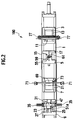
- Fig. 1 is a front view of a work locating conveyer 100 and Fig. 2 is a plan view of Fig. 1, according to an embodiment of the present invention.
- the work locating conveyer 100 has a body base 1 which is a conveyer carriage 1 extending in a horizontal direction in Fig. 1 and Fig. 2.
- first locator 11 On the first base 3, there is disposed a first locator 11 in such a manner as to move on a pair of guide rails 13 extending in the horizontal direction in Fig. I and Fig. 2.
- second base 5 On the second base 5, there is disposed a second locator 15 in such a manner as to move on one guide rail 17 extending in the horizontal direction in Fig. 1 and Fig. 2.
- third base 7 On the third base 7, there is disposed a third locator 19 in such a manner as to move on a pair of guide rails 21 extending in the horizontal direction in Fig. 1 and Fig. 2.
- fourth base 9 On the fourth base 9, there is disposed a fourth locator 23 in such a manner as to move on a pair of guide rails 25 extending in the horizontal direction in Fig. 1 and Fig. 2.
- the guide rails 13, 17, 21 and 25 each structure a moving path for allowing one of the respective locators 11, 15, 19 and 23 to follow.
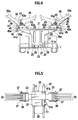
- Fig. 3 is a perspective view of a fourth locating jig 35 (main locating jig) on the fourth locator 23
- Fig. 4 is an enlarged cross section taken along the lines IV-IV in Fig. 1
- Fig. 5 is a plan view of Fig. 4
- Fig. 6 is a right side view of Fig. 4.
- the fourth locator 23 is provided with a guided portion 26 movably guided by a guide rail 25, and a bench plate 27 fixed on the guided portion 26.
- a jig supporting bracket 29 standing on the bench plate 27.
- a jig supporting plate 31 on an upper arm portion 29a (of the jig supporting bracket 29) extending horizontally on both right and left sides in Fig. 4.
- a fixture 33 is fixed to each of right and left ends on the jig supporting plate 31.
- a plurality of the fourth locating jigs 35 are fitted to the fixture 33.
- the fixture 33 is provided with a pair of fitting flanges 37 extending upward.
- a supporting shaft 39 supported by the pair of the fitting flanges 37 connects to a first end of the fourth locating jig 35, thereby making the thus connected fourth locating jig 35 pivotal.
- Each of the plurality of the fourth locating jigs 35 is individually pivotal around the supporting shaft 39, and as shown in Fig. 4, makes a displacement between i) an in-use state (positioning and supporting the work W) indicated by an actual line and ii) a non-use state (not positioning or supporting the work W) indicated by a 2-point chain line.
- An upper end of the fourth locating jig 35 in the in-use state is formed with a locating portion 35a for locating and supporting the work W.
- each of the fourth locating jigs 35 is provided with a stopper 41 which protrudes downward in the in-use state.
- the in-use state can be secured, when a stopper face 41a on the fixture 33 side of the stopper 41 abuts on a side face of the fixture 33.
- each of the fourth locating jigs 35 is provided with a stopper 43 which protrudes downward in the non-use state.
- the non-use state can be secured, when a stopper face 43a on the fixture 33 side of the stopper 43 abuts on an upper face of the fixture 33.
- a shock-absorbing material such as urethane
- a jig raising piece 45 on an opposite side to the stopper face 41a of the stopper 41.
- the jig raising piece 45 is formed with a jig raising hole 45a which is a holding hole (through hole) extending in the direction along the guide rail 25.
- the two center downward jig raising pieces 45 are longer than the other two side downward jig raising pieces 45.
- the two center jig raising holes 45a are disposed lower than the two side jig raising holes 45a, thus making an offset upward and downward from each other when the jig raising holes 45a are viewed from the direction of conveying the work W.
- an air locker 47 is fixed via a fitting portion 47a thereof (see Fig. 4 and Fig. 5).
- the air locker 47 can move along the guide rail 25 integrally with the fourth locator 23.
- a pressing piece (not shown) in the air locker 47 presses the guide rail 25 by means of air pressure, thus locking the fourth locator 23.
- a cutout 11a On an end of the fourth locator 23 on a front side of Fig. 4, there is formed a cutout 11a (see Fig. 3).
- An engaged block 51 is fixed to the cutout 11 a.
- the engaged block 51 is formed with a protrusion 51a which is a held portion protruding outward relative to the guide rail 25.
- Fig. 7 is an enlarged cross section taken along the lines VII-VII in Fig. 1
- Fig. 8 is a plan view of Fig. 7
- Fig. 9 is a right side view of Fig. 7.
- a jig supporting bracket 53 stands on the second locator 15.
- the jig supporting bracket 53 has an upper end side provided with a second locating jig 55 (sub-locating jig) for receiving the work W in the downward position.
- the second locator 15 is provided with: i) a guided portion 56 movably guided by the guide rail 17 and ii) a bench plate 57 fixed on the guided portion 56.
- the second locating jig 55 has a support pin holder 58 fixed to the jig supporting bracket 53.
- the support pin holder 58 is provided with a plurality of support pins 59 protruding upward in form of a needle (or frog, brush).
- a spring 60 which resiliently supports via the support pins 59 the work W in such a manner that the support pin 59 is moved downward when abutted by a lower face of the work W.
- the above spring 60 is received in the support pin holder 58.
- an air locker 61 via a fitting portion 61a thereof (see Fig. 8).
- the air locker 61 in Fig. 8 can move along the guild rail 17 integrally with the second locator 15.
- a pressing piece (not shown) in the air locker 61 presses the guide rail 17 by means of air pressure, thus locking the second locator 15.
- An engaged block 63 is fixed to a lower end face on the right side of the second locator 15 in Fig. 7.
- the engaged block 63 is formed with a protrusion 63a (held portion) protruding outward relative to the guide rail 17.
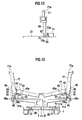
- Fig. 10 is an enlarged cross section taken along the lines X-X in Fig. 1
- Fig. 11 is a plan view of Fig. 10
- Fig. 12 is a right side view of Fig. 10.
- a pair of the third locators 19 each of which is provided with a guided portion 65 movably guided by a guide rail 21 and a bench plate 67 fixed on the guided portion 65.
- a jig supporting bracket 69 stands on the bench plate 67, where arm portions 69a each extends horizontally from an upper part of the jig supporting bracket 69.
- Inserting a head end of the third locating jig 71 into a locating hole Wa of the work W and putting the work W on a stage portion 71a of the third locating jig 71 can implement the locating operation in upper-lower direction.
- the locating position in the upper-lower direction serves as a reference position of the work W.
- an air locker 73 is fixed via a fitting portion 73a thereof (see Fig. 11). Like the air locker 47 in Fig. 3 and Fig. 5, the air locker 73 in Fig. 11 can move along the guild rail 21 integrally with the third locator 19. In a certain locating position of the third locator 19, a pressing piece (not shown) in the air locker 73 presses the guide rail 21 by means of air pressure, thus locking the third locator 19.
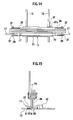
- Fig. 13 is an enlarged cross section taken along the lines XIII-XIII in Fig. 1, showing a first locating jig 77 (main locating jig) of the first locator 11, Fig. 14 is a plan view of Fig. 13, and Fig. 15 is a right side view of Fig. 14.
- the first locating jig 77 is, in general, longer than the fourth locating jig 35 in Fig. 3 to Fig. 6, and has a head end provided with a locating portion 77a for receiving the work W.
- an outer driver 79 shown in Fig. 3. From an outer part of the work locating conveyer 100, the outer driver 79 moves the locators 11, 15, 19 and 23, and turns the first locating jig 77 and the fourth locating jig 35 around the supporting shaft 39.
- the outer driver 79 is an outer driver fitted to a head end of a robot arm 200 via a fitting portion 81.
- Fig. 16 is a plan view of the outer driver 79
- Fig. 17 is a plan view of Fig. 16
- Fig. 18 is a left side view of Fig. 16.
- the outer driver 79 has the fitting portion 81 to which a base plate 83 is fixed, and is provided, on the other end of a connecting rod 85, with an end plate 87 on an opposite side to the base plate 83.
- the operation piece 89 is, as shown in Fig. 17 and Fig. 18, fitted to the connecting rod 85 via a fitting piece 91, thereby protruding more upward in Fig. 17 than the end plate 87 and more rightward than the end plate 87 in Fig. 18.
- an upper end of the operation piece 89 is formed with a dent portion 89a which serves as a holder for sandwiching and holding the protrusions 51a, 63a, 75a and 51a of the respective locators 11, 15, 19 and 23.
- a dent portion 89a which serves as a holder for sandwiching and holding the protrusions 51a, 63a, 75a and 51a of the respective locators 11, 15, 19 and 23.
- a pressing portion 89b for moving the locators 11, 15, 19 and 23 in the forward direction by pressing side faces of the protrusions 51a, 63a, 75a and 51e of the respective locators 11, 15, 19 and 23.
- the pressing portion 89b moves the locators 11, 15, 19 and 23 to the original position on the moving paths (guide rails 13, 17, 21 and 25).
- the dent portion 89a moves the locators 11, 15, 19 and 23 from the original position to the certain locating position on the moving paths (guide rails 13, 17, 21 and 25).
- the outer driver 79 is provided with a pressing rod 93 which connects the base plate 83 to the end plate 87, in an upper position of the connecting rod 85.
- the pressing rod 93 (jig returner) of the outer driver 79 in the state shown Fig. 3 presses, for example, the pressed portions 35b (four in number) of the fourth locating jigs 35 (four in number) in the position in Fig. 3, returning all at once the fourth locating jigs 35 (four in number) to the non-use state indicated by 2-point chain line in Fig. 4.
- the outer driver 79 is provided respectively with an insert pin 95 and an insert pin 97 protruding in opposite directions to each other.
- Each of the insert pin 95 and the insert pin 97 is to be inserted into one to-be-used jig raising hole 45a of the fourth locating jigs 35 (four in number), thereby moving the fourth locating jigs 35 from the non-use state (indicated by the 2-point chain line in Fig. 4) to the in-use state (indicated by the actual line in Fig. 4), serving as a locating jig selective mover.
- the insert pin 95 corresponds to two fourth locating jigs 35 on a first side, while the insert pin 97 corresponds to another two fourth locating jigs 35 on a second side.
- the pressing rod 93, the insert pin 95 and the insert pin 97 likewise, operate the first locating jig 77 in Fig. 13 to Fig. 15.
- Described at first is operation of locating the fourth locating jig 35 on the fourth locator 23, as shown in Fig. 3.
- the outer driver 79 moves toward the fourth locator 23.
- the pressed face 5 1 b of the protrusion 51a of the engaged block 51 on the fourth locator 23 side is pressed toward the air locker 47 side by means of the pressing portion 89b of the operation piece 89, to thereby move the fourth locator 23 to the original position along the guide rail 25.
- all the four fourth locating jigs 35 on each of right and left sides, as shown in Fig. 3, are in the in-use state.
- at least one of the four fourth locating jigs 35 used before may be in the in-use state on each of right and left sides.
- the outer driver 79 is to be moved in such a manner that the pressing rod 93 presses the pressed portion 35b of the fourth locating jig 35 in a proper direction. Then, from the in-use state, all the fourth locating jigs 35 are pivoted around the supporting shaft 39 extending in the direction along the guide rail 25, to thereby reach the non-use state indicated by 2-point chain line in Fig. 4. With this, as shown Fig. 19, all the four fourth locating jigs 35 arranged on each of right and left sides are in the non-use state.
- the outer driver 79 is separated from the fourth locating jig 35. Then, the operation piece 89 is moved toward a lower part of the fourth locator 23, to thereby allow the dent portion 89a of the operation piece 89 to engageably sandwich the protrusion 51a of the fourth locator 23. In this state, the outer driver 79 is so moved as to move the fourth locator 23 along the guide rail 25 in a direction away from the original position to the certain locating position.
- the outer driver 79 is detached from the fourth locator 23.
- the outer driver 79 is pivoted by 180° around a shaft center of the connecting rod 85 extending in the longitudinal direction.
- the insert pin 95 is inserted into the jig raising hole 45a of the jig raising piece 45 of one of the fourth locating jigs 35 that is to be used.
- the to-be-used fourth locating jig 35 is alone raised for the in-use state.
- Like operations are to be implemented for one of the fourth locating jigs 35 on the opposite side.
- the outer diameter of each of the insert pin 95 and the insert pin 97 is smaller than the inner diameter of the jig raising hole 45a, forming a certain gap thereberween.
- the fourth locating jig 35 is to be raised smoothly, without causing a play by the insert pin 95 and the insert pin 97 in the jig raising hole 45a.
- the two middle jig raising holes 45a are offset from the two side jig raising holes 45a, thereby the insert pin 95 and the insert pin 97 each can be preferably inserted into only the jig raising hole 45a that is to be used for the current raising operation. Otherwise, all the four jig raising holes 45a can be offset differently, allowing only one insert pin 95 or 97 to be used for the raising operation.
- the locating operation of the fourth locator 23 and the fourth locating jig 35 is thus ended.
- This locating operation is to be likewise implemented for the first locator 11 and the first locating jig 77. Specifically, the following operations are to be implemented:
- operations like those for the first locator 11 (or the fourth locator 23) are to be implemented for the second locator 15 and the third locator 19. Specifically, moving the second locator 15 and the third locator 19 to the original position ⁇ operation I) in the former paragraph ⁇ and moving the second locator 15 and the third locator 19 to the certain locating position ⁇ operation III) in the former paragraph ⁇ .
- each of the locators 11, 15, 19 and 23 is moved to the certain locating position, and the first locating jig 77 and the fourth locating jig 35 are set in the in-use state, to thereby set the work W on the locating jigs 77, 55, 71 and 35, as shown in Fig. 1.
- the third locating jig 71 which is a locating pin for the third locator 19 specifies the upper-lower position of the work W, as shown in Fig. 10.
- a plurality of the support pins 59 of the second locator 15 resiliently support the work W by means of the spring 60, suppressing deformation of the work W. Then, with this locating set, the work W is, for example, subjected to the welding.
- the outer driver 79 which is the outer driver 79 moved by the teaching of the robot (robot arm 200) is provided with the following integrated members:
- the above structure of the outer driver 79 can eliminate the need for an actuator which has crossing three axes for operation freedom. Therefore, the work locating conveyer 100 and the work locating conveyer carriage 1 can prevent complicated overall structure and control; and can easily locate, by using the outer driver 79, the locating jig disposed on the locator (11, 15, 19, 23) side.
- returning each of the fourth locating jigs 35 to the non-use state indicated by the 2-point chain line in Fig. 4 is implemented when the fourth locator 23 is in the original position.
- the present invention is, however, not limited to this.
- the returning may be implemented when the fourth locator 23 is in the certain locating position.
- raising to the in-use state (indicated by the actual line in Fig. 4) the one fourth locating jig 35 that is to be used for the current operation can be implemented in the original position, like the returning of the fourth locating jig 35 to the non-use state being implemented in the original position.
- the second locating jig 55 in Fig. 7 to Fig. 9 is not provided with the support pin 59 having the spring 60, a supporting member abutting on the lower face of the work W is to be used for supporting the work W.
- the supporting member is not to be fixed to the jig supporting bracket 53, but is made slidable along a guide rail in the upper-lower direction, with an air locker provided for locking the sliding movement.
- the second locating jig 55 provided with the above supporting member is to be held by an operation piece (which is to be provided, for example, on a face opposite to the connecting rod 85 side of the end plate 87) formed with a dent portion like the dent portion 89a of the operation piece 89, to thereby properly position the second locating jig 55 by the upper-lower movement.
- an operation piece which is to be provided, for example, on a face opposite to the connecting rod 85 side of the end plate 87
- a dent portion like the dent portion 89a of the operation piece 89
- the third locating jig 71 in Fig. 10 to Fig. 12 may be provided with a clamp mechanism for clamping the work W from upper and lower sides.
- the above third locating jig 71 can have a simple structure.
- guide rails extending in the respective directions and air lockers are to be provided, like the supporting member which is used when the support pin 59 is not provided for the second locating jig 55, as described in the former two paragraphs.
- the third locating jig 71 is to be moved to the certain position by means of the outer driver 79.
Applications Claiming Priority (1)
| Application Number | Priority Date | Filing Date | Title |
|---|---|---|---|
| JP2004378102A JP4274120B2 (ja) | 2004-12-27 | 2004-12-27 | ワーク位置決め搬送装置,ワーク位置決め搬送方法およびワーク位置決め搬送台車 |
Publications (3)
| Publication Number | Publication Date |
|---|---|
| EP1674383A2 true EP1674383A2 (fr) | 2006-06-28 |
| EP1674383A3 EP1674383A3 (fr) | 2007-06-20 |
| EP1674383B1 EP1674383B1 (fr) | 2009-02-25 |
Family
ID=35615611
Family Applications (1)
| Application Number | Title | Priority Date | Filing Date |
|---|---|---|---|
| EP05028193A Active EP1674383B1 (fr) | 2004-12-27 | 2005-12-22 | Chariot de convoyeur, procédé et convoyeur pour le positionnement d'une pièce |
Country Status (5)
| Country | Link |
|---|---|
| US (1) | US7815035B2 (fr) |
| EP (1) | EP1674383B1 (fr) |
| JP (1) | JP4274120B2 (fr) |
| CN (1) | CN1796252B (fr) |
| DE (1) | DE602005012918D1 (fr) |
Cited By (4)
| Publication number | Priority date | Publication date | Assignee | Title |
|---|---|---|---|---|
| DE102006025311A1 (de) * | 2006-05-31 | 2007-12-06 | GM Global Technology Operations, Inc., Detroit | Spannvorrichtung zur Aufnahme verschiedener Bauteiltypen |
| WO2010130904A1 (fr) * | 2009-05-12 | 2010-11-18 | Renault Sas | Dispositif pour la manipulation des pieds de support d'une structure de support de la caisse d'un vehicule automobile |
| FR2956997A1 (fr) * | 2010-03-02 | 2011-09-09 | Peugeot Citroen Automobiles Sa | Dispositif de pianotage d'outils avec un seul actionneur |
| FR2961467A1 (fr) * | 2010-06-21 | 2011-12-23 | Renault Sa | Organe de support destine a etre fixe sur une structure de support d'une caisse de vehicule automobile |
Families Citing this family (5)
| Publication number | Priority date | Publication date | Assignee | Title |
|---|---|---|---|---|
| EP2298631B1 (fr) * | 2009-09-21 | 2012-10-31 | Siemens Aktiengesellschaft | Dispositif de transport pour un dispositif de montage de véhicule |
| CN105383904B (zh) * | 2015-12-10 | 2017-09-15 | 重庆凯西驿电子科技有限公司 | 用于电解电容器的传送装置 |
| CN105890913A (zh) * | 2016-05-30 | 2016-08-24 | 清华大学苏州汽车研究院(相城) | 一种可变行程台车回位光电检测机构及碰撞模拟台车装置 |
| JP6572936B2 (ja) * | 2017-05-10 | 2019-09-11 | 住友電装株式会社 | 端子圧着装置 |
| CN112223143A (zh) * | 2020-09-23 | 2021-01-15 | 上海鑫燕隆汽车装备制造有限公司 | 柔性定位切换机构 |
Citations (2)
| Publication number | Priority date | Publication date | Assignee | Title |
|---|---|---|---|---|
| JP2002236965A (ja) | 2001-02-13 | 2002-08-23 | Fuji Photo Film Co Ltd | 金銭データ登録装置および方法 |
| JP2002263965A (ja) | 2001-03-12 | 2002-09-17 | Nissan Motor Co Ltd | 車体搬送装置 |
Family Cites Families (19)
| Publication number | Priority date | Publication date | Assignee | Title |
|---|---|---|---|---|
| US3379298A (en) * | 1966-01-28 | 1968-04-23 | Russell Co Inc Arthur | Indexing assembly machine |
| JPS5929463B2 (ja) * | 1980-11-11 | 1984-07-20 | 日産自動車株式会社 | 自動車組立における併行生産型組立装置 |
| US4773156A (en) * | 1985-09-18 | 1988-09-27 | Toyoda Gosei Co., Ltd. | Apparatus for securing parts |
| US4667805A (en) * | 1985-11-06 | 1987-05-26 | Westinghouse Electric Corp. | Robotic part presentation system |
| JPS63272434A (ja) | 1987-04-28 | 1988-11-09 | Mazda Motor Corp | 物品組付装置 |
| JP2638808B2 (ja) * | 1987-06-08 | 1997-08-06 | トヨタ自動車株式会社 | 搬送装置 |
| US5052540A (en) * | 1988-07-26 | 1991-10-01 | Honda Giken Kogyo Kabushiki Kaisha | Rotary transfer system |
| JPH02250737A (ja) | 1989-03-24 | 1990-10-08 | Fanuc Ltd | 流れ生産路における車体位置決め装置 |
| LU88002A1 (fr) * | 1990-09-07 | 1992-06-01 | Oseney Ltd | Systeme de transport et de stockage |
| JP2745841B2 (ja) * | 1991-03-11 | 1998-04-28 | 日産自動車株式会社 | 車体搬送装置 |
| US5505290A (en) * | 1993-10-15 | 1996-04-09 | Mazda Motor Corporation | Working system for practicing work on moving subject works |
| US5518109A (en) * | 1994-09-02 | 1996-05-21 | The Laitram Corporation | Conveyor drive apparatus |
| JPH08268357A (ja) | 1995-03-31 | 1996-10-15 | Mazda Motor Corp | 車両の組立方法およびその装置 |
| JP3663984B2 (ja) * | 1999-08-06 | 2005-06-22 | 日産自動車株式会社 | 車体組立方法および車体組立装置 |
| JP3627970B2 (ja) * | 1999-11-25 | 2005-03-09 | ダイハツ工業株式会社 | ワークの加工組立ライン |
| JP2001157929A (ja) | 1999-11-29 | 2001-06-12 | Daihatsu Motor Co Ltd | ワークの加工組立ライン |
| EP1293419A3 (fr) * | 2001-09-14 | 2004-04-21 | Nissan Motor Company, Limited | Appareil pour le transport de carrosseries de véhicules |
| JP4283034B2 (ja) | 2003-05-12 | 2009-06-24 | 日本信号株式会社 | トランスポンダ装置 |
| FI116218B (fi) * | 2004-02-02 | 2005-10-14 | Kone Corp | Liukukäytävän tai vastaavan paletin kytkentäjärjestely |
-
2004
- 2004-12-27 JP JP2004378102A patent/JP4274120B2/ja active Active
-
2005
- 2005-12-22 DE DE602005012918T patent/DE602005012918D1/de active Active
- 2005-12-22 EP EP05028193A patent/EP1674383B1/fr active Active
- 2005-12-23 US US11/315,586 patent/US7815035B2/en active Active
- 2005-12-27 CN CN2005101352259A patent/CN1796252B/zh active Active
Patent Citations (3)
| Publication number | Priority date | Publication date | Assignee | Title |
|---|---|---|---|---|
| JP2002236965A (ja) | 2001-02-13 | 2002-08-23 | Fuji Photo Film Co Ltd | 金銭データ登録装置および方法 |
| JP2002263965A (ja) | 2001-03-12 | 2002-09-17 | Nissan Motor Co Ltd | 車体搬送装置 |
| EP1241085A2 (fr) | 2001-03-12 | 2002-09-18 | Nissan Motor Co., Ltd. | Ligne de transfert de carrosseries de véhicule et sa méthode |
Cited By (5)
| Publication number | Priority date | Publication date | Assignee | Title |
|---|---|---|---|---|
| DE102006025311A1 (de) * | 2006-05-31 | 2007-12-06 | GM Global Technology Operations, Inc., Detroit | Spannvorrichtung zur Aufnahme verschiedener Bauteiltypen |
| WO2010130904A1 (fr) * | 2009-05-12 | 2010-11-18 | Renault Sas | Dispositif pour la manipulation des pieds de support d'une structure de support de la caisse d'un vehicule automobile |
| FR2945506A1 (fr) * | 2009-05-12 | 2010-11-19 | Renault Sas | Dispositif pour la manipulation des pieds de support d'une structure de support de la caisse d'un vehicule automobile. |
| FR2956997A1 (fr) * | 2010-03-02 | 2011-09-09 | Peugeot Citroen Automobiles Sa | Dispositif de pianotage d'outils avec un seul actionneur |
| FR2961467A1 (fr) * | 2010-06-21 | 2011-12-23 | Renault Sa | Organe de support destine a etre fixe sur une structure de support d'une caisse de vehicule automobile |
Also Published As
| Publication number | Publication date |
|---|---|
| JP2006181680A (ja) | 2006-07-13 |
| EP1674383A3 (fr) | 2007-06-20 |
| CN1796252B (zh) | 2010-08-18 |
| US7815035B2 (en) | 2010-10-19 |
| US20060143894A1 (en) | 2006-07-06 |
| EP1674383B1 (fr) | 2009-02-25 |
| DE602005012918D1 (de) | 2009-04-09 |
| JP4274120B2 (ja) | 2009-06-03 |
| CN1796252A (zh) | 2006-07-05 |
Similar Documents
| Publication | Publication Date | Title |
|---|---|---|
| EP1674383B1 (fr) | Chariot de convoyeur, procédé et convoyeur pour le positionnement d'une pièce | |
| US5943768A (en) | Automotive framing system | |
| EP1298043B1 (fr) | Procédé et dispositif d'assemblage d'une caisse de véhicule | |
| JP3927540B2 (ja) | 車体組付方法 | |
| EP0658397B1 (fr) | Dispositif de soudage pour points de structures constituées d'éléments en tÔle, en particulier de véhicules motorisés | |
| US5940961A (en) | Automotive framing system | |
| JPH0236034A (ja) | 搬送中のワークに対する作業方法及び作業装置 | |
| US4802616A (en) | System for positioning automotive vehicle side body | |
| JPH1190641A (ja) | 組立ラインにおけるワークハンドリング方法及び溶接方法 | |
| JP4761809B2 (ja) | ワークセット装置 | |
| US20140183805A1 (en) | Chuck body, machine center, and method for gripping a work object to be processed | |
| JPH06278857A (ja) | 搬送装置 | |
| JP2533667B2 (ja) | 自動車車体の溶接装置 | |
| CN215510749U (zh) | 一种大灯支架定位装置 | |
| CN110592813A (zh) | 夹紧辅助装置 | |
| JP4737135B2 (ja) | 部品投入方法および部品投入装置 | |
| CN110340575A (zh) | 一种机车顶盖焊装拼台及使用其的焊接生产线 | |
| CN215658588U (zh) | 一种翻转变位机及自动焊接工作站 | |
| JPH06156662A (ja) | オーバーヘッドハンガーおよびその自動切換装置 | |
| WO2014119504A1 (fr) | Dispositif de transport d'élément en forme de plaque | |
| CN218427871U (zh) | 一种用于对接的移动固定夹具 | |
| JP3302962B2 (ja) | 自動加工装置 | |
| JP3540956B2 (ja) | 搬送装置 | |
| JP4444674B2 (ja) | 収納棚装置 | |
| KR19980034886A (ko) | 파워 스티어링 요크의 가공을 위한 워크 로딩 시스템 |
Legal Events
| Date | Code | Title | Description |
|---|---|---|---|
| PUAI | Public reference made under article 153(3) epc to a published international application that has entered the european phase |
Free format text: ORIGINAL CODE: 0009012 |
|
| 17P | Request for examination filed |
Effective date: 20051227 |
|
| AK | Designated contracting states |
Kind code of ref document: A2 Designated state(s): AT BE BG CH CY CZ DE DK EE ES FI FR GB GR HU IE IS IT LI LT LU LV MC NL PL PT RO SE SI SK TR |
|
| AX | Request for extension of the european patent |
Extension state: AL BA HR MK YU |
|
| PUAL | Search report despatched |
Free format text: ORIGINAL CODE: 0009013 |
|
| AK | Designated contracting states |
Kind code of ref document: A3 Designated state(s): AT BE BG CH CY CZ DE DK EE ES FI FR GB GR HU IE IS IT LI LT LU LV MC NL PL PT RO SE SI SK TR |
|
| AX | Request for extension of the european patent |
Extension state: AL BA HR MK YU |
|
| 17Q | First examination report despatched |
Effective date: 20071214 |
|
| AKX | Designation fees paid |
Designated state(s): DE FR GB |
|
| GRAP | Despatch of communication of intention to grant a patent |
Free format text: ORIGINAL CODE: EPIDOSNIGR1 |
|
| GRAS | Grant fee paid |
Free format text: ORIGINAL CODE: EPIDOSNIGR3 |
|
| GRAA | (expected) grant |
Free format text: ORIGINAL CODE: 0009210 |
|
| AK | Designated contracting states |
Kind code of ref document: B1 Designated state(s): DE FR GB |
|
| REG | Reference to a national code |
Ref country code: GB Ref legal event code: FG4D |
|
| REF | Corresponds to: |
Ref document number: 602005012918 Country of ref document: DE Date of ref document: 20090409 Kind code of ref document: P |
|
| PLBE | No opposition filed within time limit |
Free format text: ORIGINAL CODE: 0009261 |
|
| STAA | Information on the status of an ep patent application or granted ep patent |
Free format text: STATUS: NO OPPOSITION FILED WITHIN TIME LIMIT |
|
| 26N | No opposition filed |
Effective date: 20091126 |
|
| REG | Reference to a national code |
Ref country code: FR Ref legal event code: PLFP Year of fee payment: 11 |
|
| REG | Reference to a national code |
Ref country code: FR Ref legal event code: PLFP Year of fee payment: 12 |
|
| REG | Reference to a national code |
Ref country code: FR Ref legal event code: PLFP Year of fee payment: 13 |
|
| REG | Reference to a national code |
Ref country code: DE Ref legal event code: R084 Ref document number: 602005012918 Country of ref document: DE |
|
| REG | Reference to a national code |
Ref country code: GB Ref legal event code: 746 Effective date: 20230922 |
|
| PGFP | Annual fee paid to national office [announced via postgrant information from national office to epo] |
Ref country code: GB Payment date: 20231121 Year of fee payment: 19 |
|
| PGFP | Annual fee paid to national office [announced via postgrant information from national office to epo] |
Ref country code: FR Payment date: 20231122 Year of fee payment: 19 Ref country code: DE Payment date: 20231121 Year of fee payment: 19 |