EP1298043B1 - Procédé et dispositif d'assemblage d'une caisse de véhicule - Google Patents
Procédé et dispositif d'assemblage d'une caisse de véhicule Download PDFInfo
- Publication number
- EP1298043B1 EP1298043B1 EP02020002A EP02020002A EP1298043B1 EP 1298043 B1 EP1298043 B1 EP 1298043B1 EP 02020002 A EP02020002 A EP 02020002A EP 02020002 A EP02020002 A EP 02020002A EP 1298043 B1 EP1298043 B1 EP 1298043B1
- Authority
- EP
- European Patent Office
- Prior art keywords
- jig
- body side
- upper section
- side upper
- section locator
- Prior art date
- Legal status (The legal status is an assumption and is not a legal conclusion. Google has not performed a legal analysis and makes no representation as to the accuracy of the status listed.)
- Expired - Lifetime
Links
Images


Classifications
-
- B—PERFORMING OPERATIONS; TRANSPORTING
- B62—LAND VEHICLES FOR TRAVELLING OTHERWISE THAN ON RAILS
- B62D—MOTOR VEHICLES; TRAILERS
- B62D65/00—Designing, manufacturing, e.g. assembling, facilitating disassembly, or structurally modifying motor vehicles or trailers, not otherwise provided for
- B62D65/02—Joining sub-units or components to, or positioning sub-units or components with respect to, body shell or other sub-units or components
Definitions
- the present invention relates to a method and an apparatus of assembling a vehicular body. More specifically, the method and the apparatus under the present invention are those which are preferable for a pre-tack welding operation by making a relative positioning between main components including a floor main, a right body side, a left body side, a roof rail and the like.
- a mixed production has a line for assembling in common various types of vehicular bodies.
- a body main pre-tack welding operation is included in the mixed production.
- United States Patent No. 5,005,277 ⁇ equivalent of Japanese Patent Examined Publication No. Heisei 8(1996)-15876 ⁇ and United States Patent No. 5,010,634 ⁇ equivalent of Japanese Patent Examined Publication No. Heisei 8(1996)-15877 ⁇ disclose the body main pre-tack welding operation where a body main is pre-tacked by making a relative positioning between a floor main, a right body side, a left body side, a roof rail and the like which constitute a skeleton of a vehicular body.
- GB-A-2 353 503 discloses an assembling method and an assembling apparatus according to the preamble of claim 1 and 4, respectively.
- any complicated relative jig arrangement i.e., jigs for locating body side upper section, roof rail and the like
- a method of assembling a vehicular body wherein a pre-tack welding operation is carried out upon positioning each of a floor main, a right body side, a left body side and a roof rail which constitute a body main component of a vehicle while relatively positioning the floor main, the right body side, the left body side and the roof rail.
- the method comprises the following operations:
- an apparatus of assembling a vehicular body comprising:
- a method of assembling a vehicular body comprising the following operations:
- the body main component is conveyed between the operations in such a manner that the body main component is carried on a pallet having such a function as to position and clamp the floor main.
- a three-dimension general locator device standing on a floor lifts up the body main component including the floor main and makes the positioning, thereby implementing the pre-tack welding operation with the body main component separated from the pallet.
- the pallet is positioned in a pallet positioning apparatus, and the body main which is positioned and clamped by the pallet is subjected to the additional welding operation.
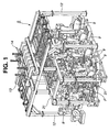
- Fig. 1 is a perspective view of the overall apparatus.
- Fig. 2 is a right side view of Fig. 1.
- Fig. 3 is a plan view of Fig. 1.
- Fig. 4 is a front view of Fig. 1, viewed from a front side.
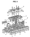
- Fig. 5 is an enlarged perspective view of essential parts in Fig. 1.
- Described at first is a basic concept of assembling the vehicular body, according to the embodiment of the present invention.
- positioning a body side itself and positioning the body side relative to mating parts were carried out by a jig and the like that are disposed outside the body side, and such jig and the like are concentrated therearound.
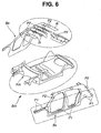
- a body side Bs is divided into two sides, namely, a lower side (lower than what is called a waist line) and an upper side (upper than the waist line), as is seen in Fig. 6.
- a portion P1 which is a locator on the lower side of body side Bs
- relative positioning of a portion P1 is carried out by a jig and the like that are disposed outside body side Bs.
- relative positioning of a portion P2 (which is a locator on the upper side of body side Bs including a roof section) according to the embodiment of the present invention is not carried out by the jig and the like that are disposed outside body side Bs, instead, by a front jig and a rear jig that are disposed otherwise on a ceiling.
- the jigs and the like can be less concentrated and less complicated outside body side Bs, thus allowing a welding robot to approach from outside body outside Bs for the pre-track welding operation.
- a floor main Fm which is a matrix of body main Bm has in itself comparatively a little likelihood to vary in shape with difference in vehicle type.
- a three-dimension general locator device can be generally used that has a three-dimensional mobility (on three orthogonal axes) and a peak end featuring a clamping function.
- the lower side (lower than what is called the waist line) of body side Bs has a portion (subjected to the jig) defining a cross section which has comparatively close similarity in shape despite difference in vehicle type.
- the above three-dimension general locator device is also useful for generalization.
- the upper side (upper than what is called the waist line) of body side Bs is likely to show a great variation in shape with difference in vehicle type. More specifically, it is a variation in panel configuration in molding.
- the upper side of body side Bs is, therefore, required of great flexibility. Taking sedan for example as a “basic” vehicle type, coupe and wagon can be regarded as “derivatives" of sedan. Making a comparison between the sedan, coupe and wagon, a front side of the upper side (including the roof section) of body side Bs has comparatively a little likelihood to vary in shape, while a rear side of the upper side of body side Bs is likely to vary in shape due to above "basic-to-derivative" difference.
- the following jigs for positioning the upper side of body side Bs are rendered independent of each other:
- One is the front jig assigned to the front side which has comparatively a little likelihood to vary in shape with difference in vehicle type
- the other is the rear jig assigned to the rear side which is likely to vary in shape with difference in vehicle type.
- the rear jig is to be adopted aggressively for variation by various vehicle types.
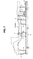
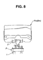
- body main Bm is temporarily assembled. More specifically, body main components including right body side Bs, left body side Bs, roof rail R and the like are assembled to each other with floor main Fm as a matrix, as is seen in Fig. 1, Fig. 2, Fig. 5 and Fig. 6. Then, the thus temporarily assembled body main Bm is positioned and clamped to a pallet P and conveyed to a site for a body main pre-tack welding operation S, as is seen in Fig. 7 and Fig. 8 (showing floor main Fm only). Pallet P can be positioned by means of a pallet positioning apparatus 1 (Fig. 4).
- the temporary assembly can be defined as below:
- a plurality of gauges 2 for stably supporting each part of floor main Fm of body main Bm (in other words, gauges 2 can receive configuration). Also provided are a locator pin unit 3 (featuring clamping function) and a clamp device 4. Body main Bm supported by the plurality of gauges 2 is positioned at locator pin unit 3, and clamped securely with locator pin unit 3 and clamp device 4.
- locator pin unit 3 (featuring clamping function) and clamp device 4 are not provided with actuator. Therefore, clamping and unclamping can be carried out by turning screws (which are attached respectively to locator pin unit 3 and clamp device 4) with an external operating means. During movement of pallet P, the above clamping state can be self-maintained.
- body main pre-tack operation S is carried out on a floor which is provided with a plurality of three-dimension general locator jigs 5 standing on a right side and a left side of the pallet positioning apparatus 1 (see Fig. 4).
- Three-dimension general locator jig 5 can locate floor main Fm.
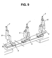
- Fig. 9 is an overall view of the three-dimension general locator jigs 5 each of which includes a locator body 6 and a locator pin unit 7.
- Locator body 6 is shaped substantially into a robot which is mobile on three orthogonal axes. Moreover, locator body 6 has a peak end provided with locator pin unit 7 featuring clamping function.
- JP4283034 discloses a locator pin unit which is similar to locator pin unit 7 according to the embodiment of the present invention.
- Pallet P carrying the temporarily assembled body main components is conveyed to the site for body main pre-tack welding operation S.
- clamp device 4 on pallet P unclamps the body main components.
- three-dimension general locator jig 5 for positioning floor main Fm in body main pre-tack welding operation S moves locator pin unit 7 in accordance with the vehicle type.
- three-dimension general locator jig 5 lifts up floor main Fm (as a support point) of the body main components.
- three-dimension general locator jig 5 also positions and clamps floor main Fm at a predetermined height.
- the body main components are separated from pallet P in body main pre-tack welding operation S.
- three-dimension general locator jigs 8 for positioning lower section of body side Bs.
- three-dimension general locator jig 8 includes a locator body which is shaped substantially into a robot mobile on three orthogonal axes and which has a peak end fitted with various gauges (for receiving configuration) and clamp devices. With the above construction, three-dimension general locator jig 8 can three-dimensionally position body side Bs itself, and also make relative positioning between body side Bs and floor main Fm.
- three-dimension general locator jigs 8 can approach the lower section of body side Bs. Then, three-dimension general locator jigs 8 can carry out three-dimensional positioning and clamping of body side Bs itself, and relative positioning between body side Bs and floor main Fm.
- Welding robots 9 can approach body main Bm from between three-dimension general locator jigs 8, so as to carry out a spot welding (as a pre-tack welding operation) to a junction between the body main components after the relative positioning.
- Front body side upper section locator jig 10 and rear body side upper section locator jig 11 are disposed on the ceiling, and are independent of each other at front side and rear side of the vehicular body respectively.
- Each of front body side upper section locator jig 10 and rear body side upper section locator jig 11 is exclusive to a single vehicle type or plural vehicle types, and can be replaced in accordance with the type of body main Bm which is subjected to body main pre-tack welding operation S --to be described afterward.
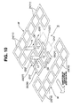
- Fig. 10 shows a schematic of a portion (in Fig. 3) that relates only to front body side upper section locator jig 10 and rear body side upper section locator jig 11.
- an operating position Q1 is defined as a position where each of front body side upper section locator jig 10 and rear body side upper section locator jig 11 is to be disposed.
- a soon-to-be replaced position Qn is defined above operating position Q1.
- Front body side upper section locator jig 10 conveyed to soon-to-be replaced position Qn is interposed between a pair of front standby positions Q12 (right and left) disposed substantially level with soon-to-be replaced position Qn, while rear body side upper section locator jig 11 conveyed to soon-to-be replaced position Qn is interposed between a pair of rear standby positions Q22 (right and left) disposed substantially level with soon-to-be replaced position Qn.
- a plurality of front jig receivers 23 are disposed on a front side of front body side upper section locator jig 10, while a plurality of rear jig receivers 24 are disposed on a rear side of rear body side upper section locator jig 11.
- a pair of frames 31 extending forward and rearward relative to the vehicular body.
- a frame 12 standing on the floor and extending sideward (rightward and leftward) relative to the vehicular body, in such a manner as to stride over frames 31.
- a front carriage slider 32 and a rear carriage slider 33 each of which acts as a secondary jig replacing means (one of three jig replacing means).
- a front lifter 13 and a rear lifter 14 each of which acts as a final jig replacing means (one of the three jig replacing means).
- front carriage slider 32 can replace front body side upper section locator jig 10 between soon-to-be replaced position Qn (disposed above operating position Q1) and front standby positions Q12 (disposed on right side and left side of soon-to-be replaced position Qn), while rear carriage slider 33 can replace rear body side upper section locator jig 11 between soon-to-be replaced position Qn (disposed above operating position Q1) and rear standby positions Q22 (disposed on right side and left side of soon-to-be replaced position Qn).
- front lifter 13 is located in a position corresponding to soon-to-be replaced position Qn and operating position Q1, to thereby replace front body side upper section locator jig 10 between soon-to-be replaced position Qn and operating position Q1, while rear lifter 14 is also located in the position corresponding to soon-to-be replaced position Qn and operating position Q1, to thereby replace rear body side upper section locator jig 11 between soon-to-be replaced position Qn and operating position Q1.
- a pair of a right carriage frame 34 and a left carriage frame 34 which are arranged sideward (cross direction of the vehicle, or upward and downward in Fig. 14) as a jig carrying area, and are coupled with each other by means of spacers 35, thus constituting a front conveyer 36.
- a rear conveyer 37 can be constituted of the pair of right carriage frame 34 and left carriage frame 34 coupled with each other by means of spacers 35.
- each of the pair of front conveyer 36 and rear conveyer 37 can slidably move on frame 12 sideward (cross direction of the vehicle, or upward and downward in Fig. 14) in a range defined by a stroke St in Fig. 15.
- Front conveyer 36 and rear conveyer 37 can make a round trip alternately, and independently of each other. More specifically, front conveyer 36 can independently move between soon-to-be replaced position Qn and front standby positions Q12 (disposed on right side and left side of soon-to-be replaced position Qn), while rear conveyer 37 can independently move between soon-to-be replaced position Qn and rear standby positions Q22 (disposed on right side and left side of soon-to-be replaced position Qn).
- front conveyer 36 is provided with a combination of three linear motion bearings, namely, a linear motion bearing 38, a linear motion 39 and a linear motion 40
- rear conveyer 37 is provided with a combination of three linear motion bearings, namely, a linear motion bearing 41, a linear motion bearing 42 and a linear motion bearing 43.
- Linear motion bearing 38, linear motion bearing 39, linear motion bearing 40, linear motion bearing 41, linear motion bearing 42 and linear motion bearing 43 (each of which is also referred to as LM guide [branded by Japanese manufacturer THK CO., LTD, where LM stands for "linear motion”] or a linear guide) are arranged sequentially from front side to rear side, and extend comparatively long --to be described afterward.
- Front conveyer 36 can move guided by linear motion bearing 38, linear motion bearing 39 and linear motion bearing 40
- rear conveyer 37 can move guided by linear motion bearing 41, linear motion bearing 42 and linear motion bearing 43.
- Front conveyer 36 for replacing front body side upper section locator jig 10 is independent of rear conveyer 37 for replacing rear body side upper section locator jig 11. Being carried on one of carriage frames 34 of front conveyer 36, each front body side upper section locator jig 10 can be positioned and caught by a jig catcher 110 (to be described afterward). Independently of front body side upper section locator jig 10, each rear body side upper section locator jig 11 can be positioned and caught by the jig catcher 110, being carried on one of carriage frames 34 of rear conveyer 37.
- each carriage frame 34 as the jig carrying area of one of front conveyer 36 and rear conveyer 37 is greater in shape (outline) than front body side upper section locator jig 10 and rear body side upper section locator jig 11.
- front body side upper section locator jig 10 can be replaced between soon-to-be replaced position Qn and front standby positions Q12 (disposed on right side and left side of soon-to-be replaced position Qn) in accordance with shift of front conveyer 36, while rear body side upper section locator jig 11 can be replaced between soon-to-be replaced position Qn and rear standby positions Q22 (disposed on right side and left side of soon-to-be replaced position Qn) in accordance with shift of rear conveyer 37.
- front body side upper section locator jig 10 can be replaced between soon-to-be replaced position Qn and front standby positions Q12 (disposed on right side and left side of soon-to-be replaced position Qn) in accordance with shift of front conveyer 36
- rear body side upper section locator jig 11 can be replaced between soon-to-be replaced position Qn and rear standby positions Q22 (disposed on right side and left side of soon-to-be replaced position Qn) in accordance with shift of rear conveyer 37.
- front body side upper section locator jig 10 can be replaced between soon-to-be replaced position Qn and operating position Q1 in accordance with upward-and-downward shift of front lifter 13, while rear body side upper section locator jig 11 can be replaced between soon-to-be replaced position Qn and operating position Q1 in accordance with upward-and-downward shift of rear lifter 14 --to be described afterward. Details of front carriage slider 32, rear carriage slider 33, front conveyer 36 and rear conveyer 37 are to be described afterward.
- front lifter 13 has a peak end fitted with a front jig changer 44 as a jig gripping means
- rear lifter 14 has a peak end fitted with a rear jig changer 45 as a jig gripping means.
- front jig changer 44 and rear jig changer 45 can move upward and downward in a predetermined stroke.
- Front body side upper section locator jig 10 carried by front conveyer 36 (carriage frame 34) is conveyed to soon-to-be replaced position Qn in a state that front jig changer 44 is disposed at an uppermost position. Then, front body side upper section locator jig 10 can autonomously engage with a part of front jig changer 44 of front lifter 13, in such a manner that front body side upper section locator jig 10 is also carried by front jig changer 44. Then, jig catcher 110 (see Fig. 14) of front conveyer 36 may release front body side upper section locator jig 10, to thereby allow front lifter 13 to lower front body side upper section locator jig 10 to operating position Q1 --to be described afterward.
- rear body side upper section locator jig 11 carried by rear conveyer 37 (carriage frame 34) is conveyed to soon-to-be replaced position Qn in a state that rear jig changer 45 is disposed in an uppermost position. Then, rear body side upper section locator jig 11 can autonomously engage with a part of rear jig changer 45 of rear lifter 14, in such a manner that rear body side upper section locator jig 11 is also carried by rear jig changer 45. Then, jig catcher 110 (see Fig. 14) of rear conveyer 37 may release rear body side upper section locator jig 11, to thereby allow rear lifter 14 to lower rear body side upper section locator jig 11 to operating position Q1 --to be described afterward.
- front jig changer 44 at the peak end of front lifter 13 attachably and removably carries front body side upper section locator jig 10
- rear jig changer 45 at the peak end of rear lifter 14 attachably and removably carries rear body side upper section locator jig 11.
- front lifter 13 and rear lifter 14 stand by in a state that each of front body side upper section locator jig 10 and rear body side upper section locator jig 11 is located in operating position Q1 in the middle by means of a locator pin 46 (see Fig. 12, Fig. 13, Fig. 40 and Fig. 41) on frame 31.
- locator pin 46 acts as a reference member. Details of front lifter 13 and rear lifter 14 are to be described afterward.
- front lifter 13 can lower front body side upper section locator jig 10 to a lowermost position.
- locator pin 46 works as the reference member to locate front body side upper section locator jig 10 on frame 31.
- a front jig body 16 shaped substantially into a rectangle defines four lower corners each of which is formed with a locator sleeve 47 fitting over locator pin 46.
- a front auxiliary frame 48 extending downward from front jig body 16.
- Front auxiliary frame 48 suspends a plurality of locator pin units 17 and locator pin units 49 (actuated by an air cylinder, and featuring clamping function).
- Also suspended from front auxiliary frame 48 include a clamp device 18 and a clamp device 50 (actuated by the air cylinder, and featuring clamping function).
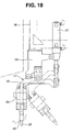
- Locator pin unit 17, locator pin unit 49, clamp device 18 and clamp device 50 can locate and clamp the upper section of body side Bs (namely, a section in the vicinity of the roof), roof rail R, and the like. Moreover, locator pin unit 17, locator pin unit 49, clamp device 18 and clamp device 50 can make a relative positioning between the upper section of body side Bs, temporarily assembled roof rail R, and the like.
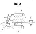
- a bracket 53 equipped with a swing arm 52 which is swingable by means of an air cylinder 51.
- Swing arm 52 has a peak end fitted with a locator pin 56 having a clamp finger 55.
- Air cylinder 54 can allow clamping and unclamping operations of locator pin 56.
- locator pin 56 is inserted into a locator hole defined in front roof rail R.
- the clamp finger 55 can implement clamping and unclamping operations, referring to locator pin 56 which is located as reference point.
- Locator pin unit 49 in Fig. 16 with no swing arm 52 is not swingable.
- Locator pin unit 49 is, however, the same as locator pin unit 17 in Fig. 18 and Fig. 19 in other constructive aspects, and can locate and clamp members including a roof rail reinforce, a roof reinforce center and the like.
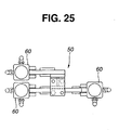
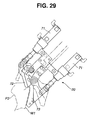
- clamp device 18 is fitted with a pair of a clamp lever 58 and a clamp lever 59 which are independent of each other, as is seen in Fig. 20 to Fig. 22.
- Each of clamp lever 58 and clamp lever 59 can be driven by an air cylinder 57.
- Clamp lever 58 and clamp lever 59 have a function of clamping, for example, a body side outer W1 and a roof side rail R1 together.
- Coupler 64 in the middle on an upper face of front jig body 16 of front body side upper section locator jig 10.
- Coupler 64 has a first side formed with a pair of hooks 65 having a cross section formed substantially into an alphabetical T, and a second side formed with the same pair of hooks 65.
- Coupler 64 is an aggregation of connectors which supply compressed air (hydraulic energy) to the air cylinders (actuator) of locator pin unit 17, locator pin unit 49, clamp device 18, clamp device 50 and the like.
- Coupler 64 is also an aggregation of connectors which supply electric power to various pieces of electronic equipment attached to front jig body 16 and which receive signals from various sensors.
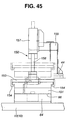
- front body side upper section locator jig 10 (to be located in operating position Q1) in soon-to-be replaced position Qn is moved from front conveyer 36 to front jig changer 44 of front lifter 13, a coupler 151 of front lifter 13 can couple with coupler 64 via a coupler mating face 66, as is seen in Fig. 44 --to be described afterward.
- Hook 65 acts as a mechanical connection between front body side upper section locator jig 10 and front jig changer 44 of front lifter 13, when front body side upper section locator jig 10 is conveyed to soon-to-be replaced position Qn --to be described afterward.
- hook 65 in a period when front body side upper section locator jig 10 supported by front conveyer 36 is transferred from front standby position Q12 to soon-to-be replaced position Qn, hook 65 can autonomously mate in a hook rail 152 of front jig changer 44. Thereby, hook 65 can be guided and supported by hook rail 152.
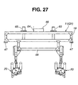
- rear body side upper section locator jig 11 fundamental construction of rear body side upper section locator jig 11 is substantially the same as that of front body side upper section locator jig 10.
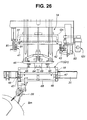
- a rear auxiliary frame 68 disposed below a rear jig body 19.
- a plurality of clamp devices 20 driven by an air cylinder are secured to rear auxiliary frame 68.
- Clamp devices 20 locate and clamp body side Bs.
- clamp devices 20 make relative positioning between body side Bs and rear pillar.
- Rear body side upper section locator jig 11 is also provided with locator sleeve 47, coupler 64, hook 65 and the like which are the same as those of front body side upper section locator jig 10.
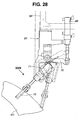
- clamp device 20 is fitted with a swing frame 70 swingable by means of an air cylinder 69, and a pair of a right clamp lever 72 and a left clamp lever 73 swingable respectively by means of air cylinders 71.
- Clamp device 20 can make a relative positioning between body side outer W1 and a rear pillar inner P3.
- Front extended frame 21 is provided with totally eight front jig receivers 23 as storage area W for storing eight types of front body side upper section locator jigs 10, as is seen in Fig. 10.
- rear extended frame 22 is provided with totally eight rear jig receivers 24 as storage area W for storing eight types of rear body side upper section locator jigs 11, as is seen in Fig. 10.
- each of the storage areas W namely, eight front jig receivers 23 and eight rear jig receivers 24
- a front jig replacing robot 25 and a rear jig replacing robot 26 act as a primary jig replacing means (one of the three jig replacing means) and is mobile sideward.
- Front jig replacing robot 25 has its own liberty as well as above sideward mobility, thereby replacing front body side upper section locator jig 10 between storage area W (eight front jig receivers 23) and front standby position Q12 (right or left).
- rear jig replacing robot 26 has its own liberty as well as above sideward mobility, thereby replacing rear body side upper section locator jig 11 between storage area W (eight rear jig receivers 24) and rear standby position Q22 (right or left).
- each of eight rear body side upper section locator jigs 11 is predetermined (numbered) by the number of the one of the eight rear jig receivers 24.
- rear body side upper section locator jig 11 for one vehicle type is disposed in operating position Q1, one of eight rear jig receivers 24 (rear storage area W) is left vacant.
- rear body side upper section locator jig 11 is absent from soon-to-be replaced position Qn and rear standby positions Q22 (right and left), although rear conveyer 37 is positioned in such a manner as to stride over operating position Q1 and one rear standby position Q22 (either right or left).
- rear conveyer 37 constituted of the pair of carriage frames 34 makes the repeated round trips in stroke St (see Fig. 15). Therefore, a control system can determine in advance which of rear standby position Q22 (right side of soon-to-be replaced position Qn) and rear standby position Q22 (left side of soon-to-be replaced position Qn) is prepared for the "other (see former paragraph)" of the pair of carriage frames 34 when the "one (see former paragraph)" of carriage frames 34 is standing by in soon-to-be replaced position Qn.
- rear jig replacing robot 26 can select one of rear body side upper section locator jigs 11 stored in the storage area (rear jig receivers 24). Then, rear jig replacing robot 26 transfers thus selected rear body side upper section locator jig 11 to carriage frame 34 that is disposed in one of rear standby position Q22 (right side of soon-to-be replaced position Qn) and rear standby position Q22 (left side of soon-to-be replaced position Qn).
- rear lifter 14 may lift up rear body side upper section locator jig 11 which so far operated in operation position Q1. Then, rear lifter 14 may put rear body side upper section locator jig 11 on the carriage frame 34 that is standing by in soon-to be replaced position Qn, and may locate and support rear body side upper section locator jig 11 in soon-to be replaced position Qn.
- rear body side upper section locator jig 11 thus transferred to carriage frame 34 is, at this point in time, still (also) carried by rear jig changer 45 of rear lifter 14.
- one of carriage frames 34 of rear conveyer 37 carries 'used' rear body side upper section locator jig 11 while the other of carriage frames 34 of rear conveyer 37 carries 'to-be-used' rear body side upper section locator jig 11.
- Rear lifter 14 is to be described in detail afterward.
- the above 'used' rear body side upper section locator jig 11 can be autonomously released from rear jig changer 45 of rear lifter 14 in accordance with the movement of rear conveyer 37.
- the above 'to-be-used' rear body side upper section locator jig 11 can autonomously and mechanically engage with rear jig changer 45 of rear lifter 14.
- the 'used' rear body side upper section locator jig 11 which was so far in soon-to-be replaced position Qn can be ejected to one of rear standby position Q22 (right side of soon-to-be replaced position Qn) and rear standby position Q22 (left side of soon-to-be replaced position Qn), while the 'to-be-used' rear body side upper section locator jig 11 which so far kept standing by in the other of rear standby position Q22 (right side of soon-to-be replaced position Qn) and rear standby position Q22 (left side of soon-to-be replaced position Qn) can be conveyed to and positioned in soon-to-be replaced position Qn.
- conveyed and positioned fresh ('to-be-used') rear body side upper section locator jig 11 is moved from soon-to-be replaced position Qn down to operating position Q1.
- rear body side upper section locator jig 11 With rear body side upper section locator jig 11 thus replaced, the routine conveys the next type of body main Bm to the site for body main pre-tack welding operation S. Then, positioning operation can soon be started for the thus conveyed next type of body main Bm. Simultaneously with this (or in parallel with the above positioning operation), rear jig replacing robot 26 may return the 'used' rear body side upper section locator jig 11 (which is standing by in rear standby position Q22) to rear jig receiver 24 (storage area W). Basically, the above jig replacing operation of rear body side upper section locator jig 11 can be carried out likewise for front body side upper section locator jig 10.
- front body side upper section locator jig 10 and rear body side upper section locator jig 11 are independent of each other for the following causes:
- Front body side upper section locator jigs 10 a maximum of eight types of front body side upper section locator jigs 10 and a maximum of eight types of rear body side upper section locator jigs 11 can be stored.
- Front body side upper section locator jig 10 is, however, commonly used for various vehicle types, as described above.
- front body side upper section locator jig 10 can be smaller in number than rear body side upper section locator jig 11, for working sufficiently for a mixed production.
- front carriage slider 32 rear carriage slider 33, front conveyer 36, rear conveyer 37, front lifter 13, rear lifter 14 and the like which constitute basic components of the apparatus of assembling the vehicular body.
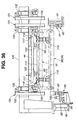
- frame 12 used for body main pre-tack welding operation S is fitted with three beams, that is, a beam 80, a beam 81, a beam 82 which are in parallel with each other and extend in a sideward direction (substantially orthogonal to a direction of conveying body main Bm) of body main Bm to be assembled.
- Linear motion bearing 38 and linear motion bearing 39 extend long and are laid on beam 80
- linear motion bearing 40 and linear motion bearing 41 extend long and are laid on beam 81
- linear motion bearing 42, and linear motion bearing 43 extend long and are laid on beam 82.
- FIG. 14 shows a basic construction having a lateral symmetry, and therefore parts and sections substantially the same are denoted by the same numerals in right and left.
- each of linear motion bearing 38, linear motion bearing 39 and linear motion bearing 40 (and, linear motion bearing 41, linear motion bearing 42 and linear motion bearing 43) is constituted of a long guide rail 83 (guide way) and a slider 84.
- Guide rails 83 are fixed to respective beam 80, beam 81 and beam 82 each of which has a cross section shaped substantially into an alphabetical I.
- Slider 84 is slidably guided by guide rail 83.
- Slider 84 of each of linear motion bearing 38, linear motion bearing 39 and linear motion bearing 40 can couple with front conveyer 36 (carriage frame 34), while slider 84 of each of linear motion bearing 41, linear motion bearing 42 and linear motion bearing 43 (rear side) can couple with rear conveyer 37 (carriage frame 34).
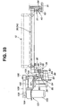
- Two middle linear motion bearings that is, linear motion bearing 40 and linear motion bearing 41 are independent of each other. More specifically, linear motion bearing 40 is for front conveyer 36, while linear motion bearing 41 is for rear conveyer 37. Contrary to the independence of the two middle linear motion bearings, two front linear motion bearings act as an integrated member, while two rear linear motion bearings act as an integrated member. More specifically, as is seen in Fig.
- slider 84 of linear motion bearing 38 couples with slider 84 of linear motion bearing 39 by way of a coupler plate 85, while as can be assumed from Fig. 33, slider 84 of linear motion bearing 42 couples with slider 84 of linear motion bearing 43 by way of coupler plate 85.
- auxiliary rail 86 is fixed to a side section of beam 80. Fixed on auxiliary rail 86 are guide rails 83 of respective two front linear motion bearings, that is, linear motion bearing 38 and linear motion bearing 39.
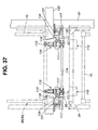
- a plurality of hinges 90 interposed between coupler plate 85 (coupling sliders 84 of respective linear motion bearing 38 and linear motion bearing 39) and a front end of carriage frame 34.
- Hinge 90 has a hinge pin 89 which is arranged in parallel with a direction of front conveyer 36's travel, and couples a pair of a hinge bracket 87 and a hinge bracket 88.
- Hinge bracket 87 couples with coupler plate 85, while hinge bracket 88 couples with carriage frame 34 on front conveyer 36.
- front conveyer 36 can be slidably guided by three linear motion bearings, that is, linear motion bearing 38, linear motion bearing 39 and linear motion bearing 40, and thereby front conveyer 36 is pivotal or swingable around hinge pin 89.
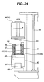
- floating mechanism 91 interposed between linear motion bearing 40 (rear side in Fig. 33) and rear end of front conveyer 36 (carriage frame 34).
- floating mechanism 91 has a pin 93 defining an end formed with a substantially hemispherical section 92. Pin 93 protrudes downward from carriage frame 34.
- a holder 94 receiving hemispherical section 92 with clearance is fixed to slider 84 of linear motion bearing 40 together with base plate 95.
- holder 94 is divided into two halves.
- a concave spherical plate 74 abutting spherically on hemispherical section 92, to thereby form a spherical bearing 96.
- a compression coil spring 97 biases pin 93 downward, to thereby press hemispherical section 92 to spherical plate 74.
- pin 93 can be elastically sustained in such a manner as to move upward and downward relative to slider 84 of linear motion bearing 40.
- pin 93 can be inclined and swingable, as indicated by an arrow D in Fig. 34.
- entire part of front conveyer 36 can be displaceable upward and downward at least on linear motion bearing 40's side, and simultaneously with this, is pivotal or swingable around hinge pin 89, thus causing a floating state (floatability) where the entire part of front conveyer 36 is swingable on a flat face substantially orthogonal to the direction of front conveyer 36's travel.
- compression coil spring 97 in holder 94 can also act as a return spring for returning pin 93 to its neutral position autonomously, in addition to the floatability brought about as described above.
- auxiliary beam 99 there is provided a rack 100 fixed on coupler plate 85 and extending in the direction of front conveyer 36's travel.
- Auxiliary beam 99 also extends in the direction of front conveyer 36's travel.
- Travel drive mechanism 101 (for driving front conveyer 36) on beam 80. Travel drive mechanism 101 has such a construction that an upright drive motor 103 which is rotatable forward and reward is mounted on a bracket 102 on beam 80.
- a follower shaft 105 in parallel with a motor revolution shaft 104 is born by bracket 102.
- a driven pulley 106 At an upper end of follower shaft 105, there is provided a driven pulley 106; while at a lower end of follower shaft 105, there is provided a pinion 107 meshing with rack 100.
- motor revolution shaft 104 is fitted with a drive pulley 108.
- a timing belt 109 winds in an area between drive pulley 108 and driven pulley 106.
- Driving drive motor 103 allows pinion 107 to rotate in its given position.
- Rack 100 meshing with thus rotated pinion 107 can move front conveyer 36 in predetermined stroke St.
- linear motion bearing 38, linear motion bearing 39 and linear motion bearing 40 of front conveyer 36 are basically the same in construction as their counterparts of rear conveyer 37 in Fig. 14 and Fig. 15. Also the same in construction include front conveyer 36 itself, travel drive mechanism 101 and the like.
- linear motion bearing 38, linear motion bearing 39, linear motion bearing 40, linear motion bearing 41, linear motion bearing 42 and linear motion bearing 43 referred to as LM guide [branded by Japanese manufacturer THK CO., LTD, where LM stands for "linear motion”], linear guide and the like for commercial use
- LM guide branded by Japanese manufacturer THK CO., LTD, where LM stands for "linear motion”
- linear guide and the like for commercial use are used as a slide guide mechanism, despite comparatively long stroke St of each of front conveyer 36 and rear conveyer 37.
- the above apparatus of assembling vehicular body has a special feature in terms of construction as described below:
- FIG. 36 to Fig. 38 show details of front conveyer 36.
- front conveyer 36 is so constituted that two carriage frames 34 for carrying front body side upper section locator jigs 10 are coupled with each other by way of spacers 35, as described above.
- a pair of jig catchers 110 are disposed on two opposing sides of each of carriage frames 34.
- jig catcher 110 is of a toggle type, and directly positions and catches front body side upper section locator jig 10.
- Jig catcher 110 is constituted of a jig support arm 113, a synchronous shaft 114, a link 115, an intermediary link 116, a cam follower lever 117 and a cam follower roller 118.
- Jig support arm 113 acts as a member for supporting front body side upper section locator jig 10 and rear body side upper section locator jig 11, and is shaped substantially into a bell crank.
- jig support arm 113 is rotatably supported to a bracket 111 of carriage frame 34 by way of a hinge pin 112.
- Synchronous shaft 114 is long and rotatably supported to bracket 111.
- Link 115 coaxially and unitedly couples with synchronous shaft 114, in such a manner as to form a key.
- Intermediary link 116 links jig support arm 113 with link 115.
- cam follower lever 117 is coaxial and united with both two ends of synchronous shaft 114, in such a manner as to form a key.
- Cam follower roller 118 is rotatably fitted to cam follower lever 117.
- a seat 120 for receiving a seat pad 119 which is disposed on carriage frame 34's side, as is seen in Fig. 38.
- Jig support arm 113 is pivotal between a jig positioning area Y1 (depicted by actual lines in Fig. 38 and an escape area Y2 (depicted by dotted lines in Fig. 38).
- adjacent jig catchers 110 share a single synchronous shaft 114, so that jig support arms 113 of adjacent jig catchers 110 can move synchronously with each other.
- a tensile coil spring 122 between a projection 121 and link 115 in such a manner as to tense projection 121 and link 115.
- Tensile coil spring 122 continuously biases jig support arm 113 toward jig positioning area Y1, as is seen in Fig. 38.
- biasing force by tensile coil spring 122 allows intermediary link 116 to abut on a stopper section 123 which is formed on an end face of bracket 111.
- jig support arm 113 can stand by in jig positioning area Y1, with link 115 and intermediary link 116 arranged substantially linearly.
- a shaft line L1 through an axial center (rotary center of link 115 and cam follower lever 117) of synchronous shaft 114 is herein defined as a reference.
- a pin 124 coupling link 115 and intermediary link 116 and a pin 125 coupling intermediary link 116 and jig support arm 113 are shifted from shaft line L1 toward a rotary center (hinge pin 112) of jig support arm 113 by a predetermined distance ⁇ , thereby causing a state of what is called being over dead point.
- At least jig support arm 113 can be prevented from pivoting toward escape area Y2, even if full weight of front body side upper section locator jig 10 is applied to jig support arm 113.
- jig catcher 110 can secure the state shown in Fig. 38 (self locking).
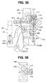
- Fig. 39 shows a state where an operator cam 134 of a lock mechanism 131 (to be described afterward) presses downward cam follower lever 117 fitted with cam follower roller 118.
- jig support arm 113 can be pivoted to escape area Y2 and stay at escape area Y2, as is depicted by the imaginary lines in Fig. 38 (self locking).
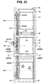
- auxiliary frame 130 which is disposed in such a manner as to stride over beam 80, beam 81 and beam 82, as is seen in Fig. 14, Fig. 15 and Fig. 31.
- auxiliary frame 130 is fitted with lock mechanisms 131 each of which allows jig support arm 113 of jig catcher 110 to move from jig positioning area Y1 to escape area Y2 and stay in escape area Y2 (locking state).
- lock mechanism 131 is constituted of a bracket 132, a drive cylinder 133 and operator cam 134.
- Drive cylinder 133 is shaped substantially into a clevis, and fitted to bracket 132 in such a manner as to posture vertical.
- Operator cam 134 is shaped substantially into a Japanese katakana character " " and disposed below drive cylinder 133 in such a manner as to connect to a piston of drive cylinder 133. Moreover, operator cam 134 can move upward and downward together with the piston of drive cylinder 133.
- hook 65 disposed on front body side upper section locator jig 10 mates into hook rail 152 of front jig changer 44 disposed on front lifter 13.
- cam follower roller 118 at the peak end of cam follower lever 117 of each of jig catchers 110 can mate into operator cam 134 (space defined by then " "). Then, pressing cam follower lever 117 downward by lowering operator cam 134 as is seen in Fig. 38 and Fig. 39, when front body side upper section locator jig 10 is supported by front lifter 13, will allow jig support arm 113 of each of jig catchers 110 to move from jig positioning area Y1 to escape area Y2. Thereby, front body side upper section locator jig 10 can be released from each of jig support arms 113 -to be described afterward.
- lock mechanism 131 and the like of front conveyer 36 are substantially the same in construction as their counterparts of rear conveyer 37.
- front conveyer 36 itself is substantially the same in construction as rear conveyer 37.
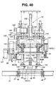
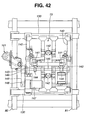
- Fig. 40 to Fig. 43 show details of front lifter 13 which acts as the final jig replacing means (one of the three jig replacing means) for replacing front body side upper section locator jig 10 between soon-to-be replaced position Qn and operating position Q1.
- Fig. 40 to Fig. 43 show details of front lifter 13 that is shown in Fig. 2, Fig. 12 and Fig. 16.
- front lifter 13 is mounted to auxiliary frame 130 by way of a cross beam 140.
- Front lifter 13 has the peak end (lower end) fitted with front jig changer 44 as the jig gripping means (or a jig gripper).
- Front jig changer 44 is shaped substantially into a rectangle.
- front jig changer 44 is suspended to the peak end (lower end) of front lifter 13 by way of a pair of guide posts 141 and a pair of assistant cylinders 142 (such as air cylinder) in such a manner as to move upward and downward.
- shown in Fig. 41 is only one of the pair of assistant cylinders 142.
- front jig changer 44 may keep standing by in a position as high as soon-to-be replaced position Qn (uppermost).
- a rack 143 is fixed to each of guide posts 141 in a lengthwise direction. Moreover, a pinion 144 meshing with rack 143 is coaxially united with a drive shaft 145.
- Drive shaft 145 is rotatably born with a plurality of bearings.
- a driven pulley 146 is fixed to a first end of drive shaft 145, while a drive pulley 148 is fixed to a revolution shaft of a drive motor 147.
- a timing belt 149 winds in an area between drive pulley 148 and driven pulley 146.
- drive motor 147 allows pinion 144 to make forward and reverse rotations, to thereby extend and compress assistant cylinder 142.
- front jig changer 44 can move upward and downward between soon-to-be replaced position Qn (uppermost) and operating position Q1 (lowermost).
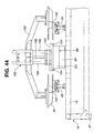
- coupler 151 (circular) which is supported by a coupler attaching-removing mechanism 150.
- coupler 151 On a first side and a second side of coupler 151, there are provide hook rails 152 extending comparatively long in the direction along front conveyer 36's travel.
- coupler 151 is an aggregation of connectors supplying compressed air (hydraulic energy) to the actuators of locator pin unit 17, clamp device 18 and the like (see Fig. 16 and Fig. 17) of front body side upper section locator jig 10.
- Coupler 151 is also an aggregation of connectors which supply electric power to various pieces of electronic equipment attached to front jig body 16 and which receive signals from various sensors. As is seen in Fig. 44 to Fig. 46, coupler 151 is fitted to a nail section 154 of a circular chuck 153 of coupler attaching-removing mechanism 150 with predetermined radial clearance and upper-and-lower clearance, in such a manner as to float (featuring floatability).
- Coupler attaching-removing mechanism 150 is provided with an attaching-removing cylinder 157 (having a guide rod 156) which is fitted to a frame 155 (in a form of an arch [see Fig. 44]) disposed on front jig changer 44. As is seen in Fig. 44, chuck 153 is coupled with peak ends (lower) of piston rod 158 and guide rod 156 of coupler attaching-removing mechanism 150.
- front body side upper section locator jig 10 (to be conveyed to operating position Q1) on front conveyer 36 is properly positioned in soon-to-be replaced position Qn.
- hook 65 of front body side upper section locator jig 10 is guided and carried by hook rail 152.
- Lowering chuck 153 (see Fig. 44 to Fig. 46) in the above state allows coupler 64 of front body side upper section locator jig 10 to couple with coupler 151 of front jig changer 44 by way of coupler mating face 66.
- the above connectors (supplying compressed air [hydraulic energy]) and connectors (supplying electric power) can be coupled with each other, thereby supplying compressed air and electric power to front body side upper section locator jig 10.
- lock mechanism 136 shown in Fig. 36 and Fig. 40 may operate, to thereby pivot jig support arm 113 (see Fig. 38) of each of jig catchers 110 to escape area Y2 for locking at escape area Y2.
- front body side upper section locator jig 10 can be released from jig catcher 110. With this, front body side upper section locator jig 10 is supported only by engagement between hook 65 and hook rail 152 of front jig changer 44.
- locator pin 46 is the reference member for locating front body side upper section locator jig 10 in operating position Q1.
- front body side upper section locator jig 10 can be insensitive to any influence which may be caused by front lifter 13, thereby achieving accurate positioning (mechanical positioning) of front body side upper section locator jig 10 in operating position Q1 referring to locator pins 46.
- front lifter 13 is substantially the same as that of rear lifter 14.
- the plurality of three-dimension general locator jigs 5 standing on the right side and the left side of the pallet positioning apparatus 1 may lift the entire part of body main Bm, with floor main Fm as supporting section. With this, the entire part of body main Bm can be positioned and supported at a predetermined height. As a result, body main Bm can be temporarily separated from pallet P. Then, three-dimension general locator jigs 5 may clamp body main Bm by clamping function incorporated in locator pin unit 7.
- right and left three-dimension general locator jigs 8 for body side Bs may operate to position lower section of body side Bs itself by means of the plurality of gauges and clamp devices, and also make relative positioning between lower section of body side Bs and floor main Fm.
- the plurality of locator pin units 17, locator pin units 49, clamp devices 18 and clamp devices 50 (see Fig. 16 and Fig. 17) which are attached to front body side upper section locator jig 10 positioned in operating position Q1 may operate to position the upper section of body side Bs itself, and make relative positioning between the upper section of body side Bs, the plurality of roof rails R and the like, while the plurality of clamp devices 20 (see Fig. 26 and Fig. 27) which are attached to rear body side upper section locator jig 11 positioned in operating position Q1 may also operate to position the upper section of body side Bs itself, and make relative positioning between the upper section of body side Bs, the plurality of roof rails R and the like.
- the plurality of welding robots 9 standing by outside three-dimension general locator jigs 8 may operate. More specifically, a spot welding gun at a peak end of a robot arm comes from between three-dimension general locator jigs 8 and approaches body side Bs, so as to implement spot welding (for the number of spots as required) as pre-tack welding operation S to the junction between body main components. After completing the spot welding with the required number of spots, body main Bm can be secured in accuracy.
- each of front body side upper section locator jig 10, rear body side upper section locator jig 11 and three-dimension general locator jigs 8 may release body main Bm, and escape from body main Bm.
- three-dimension general locator jig 5 for floor main Fm is unclamped.
- Lowering body main Bm at reduced speed can allow body main Bm to be positioned again on pallet P which is standing by below body main Bm.
- clamp devices and the like of pallet P may operate to position and clamp body main Bm again.
- pallet P carrying body main Bm is positioned by means of a pallet positioning apparatus substantially the same as pallet positioning apparatus 1 described above. Then, body main Bm can be subjected to the additional welding operation without being separated from pallet P for the number of spots required.
- the additional welding operation having a large number of spots (known) is usually divided into several sub-operations.
- the additional welding operation is carried out without separating body main Bm from pallet P, thus eliminating needs for attaching high-performance three-dimension general locator jigs as those (three-dimension general locator jig 5 and three-dimension general locator jig 8) used for body main pre-tack welding operation S.
Claims (20)
- Procédé d'assemblage d'une caisse de véhicule dans lequel une opération de soudure de pointage préalable (S) est exécutée lors du positionnement de chacun d'un bas de caisse principal (Fm), d'un côté droit de caisse (Bs), d'un côté gauche de caisse (Bs) et d'un longeron de toit (R) qui constituent un composant principal de la caisse (Bm) d'un véhicule tout en positionnant relativement le bas de caisse principal (Fm), le côté droit de caisse (Bs), le côté gauche de caisse (Bs) et le longeron de toit (R), le procédé comprenant l'étape suivante consistant à :positionner le bas de caisse principal (Fm) et exécuter le positionnement relatif entre le bas de caisse principal (Fm) et la section inférieure du côté de la caisse en utilisant un dispositif de positionnement général en trois dimensions (5, 8) qui repose sur un sol, caractérisé en ce que le procédé comprend en outre l'étape suivante consistant à :positionner chacun du côté droit de la caisse (Bs), du côté gauche de la caisse (Bs) et du longeron de toit (R) et exécuter le positionnement relatif entre la section supérieure du côté de la caisse et le longeron de toit (R), en utilisant un gabarit de positionnement de la section supérieure du côté avant de la caisse (10) et un gabarit de positionnement de la section supérieure du côté arrière de la caisse (11) qui sont suspendus à un plafond et sont indépendants l'un de l'autre dans une direction vers l'avant et vers l'arrière de la caisse de véhicule, et dont chacun peut être remplacé en fonction d'un type du véhicule.
- Procédé d'assemblage de la caisse de véhicule selon la revendication 1, dans lequel :le gabarit de positionnement de la section supérieure du côté avant de la caisse (10) et le gabarit de positionnement de la section supérieure du côté arrière de la caisse (11) peuvent servir à un seul type de véhicule ou à plusieurs types de véhicules ;chacun du gabarit de positionnement de la section supérieure du côté avant de la caisse (10) et du gabarit de positionnement de la section supérieure du côté arrière de la caisse (11) pour le type du véhicule est stocké dans une zone de stockage (W ; 23, 24) à proximité d'une position d'utilisation réelle (Q1), et chacun du gabarit de positionnement de la section supérieure du côté avant de la caisse (10) et du gabarit de positionnement de la section supérieure du côté arrière de la caisse (11) peut être remplacé entre la position d'utilisation (Q1) et la zone de stockage (W ; 23, 24) en fonction du type de véhicule qui doit être assemblé.
- Procédé d'assemblage de la caisse de véhicule selon la revendication 2, dans lequel :le gabarit de positionnement de la section supérieure du côté avant de la caisse (10) sert à positionner une section antérieure de la caisse de véhicule ;le gabarit de positionnement de la section supérieure du côté arrière de la caisse (11) sert à positionner une section postérieure de la caisse de véhicule, la section postérieure étant plus susceptible de varier dans sa forme moulée que la section antérieure en fonction d'une différence dans le type de véhicule ; etle gabarit de positionnement de la section supérieure du côté avant de la caisse (10) est plus petit en nombre total que le gabarit de positionnement de la section supérieure du côté arrière de la caisse (11).
- Dispositif d'assemblage d'une caisse de véhicule, pour exécuter une opération de soudure de pointage préalable (S) lors du positionnement de chacun d'un bas de caisse principal (Fm), d'un côté droit de caisse (Bs), d'un côté gauche de caisse (Bs) et d'un longeron de toit (R) qui constituent un composant principal de la caisse (Bm) d'un véhicule tout en positionnant relativement le bas de caisse principal (Fm), le côté droit de caisse (Bs), le côté gauche de caisse (Bs) et le longeron de toit (R), le dispositif comprenant :un dispositif de positionnement général en trois dimensions (5, 8) qui repose sur un sol, pour positionner le bas de caisse principal (Fm) et exécuter le positionnement relatif entre le bas de caisse principal (Fm) et la section inférieure du côté de la caisse, caractérisé en ce que le dispositif comprend en outre :un gabarit de positionnement de la section supérieure du côté avant de la caisse (10) et un gabarit de positionnement de la section supérieure du côté arrière de la caisse (11) qui sont suspendus à un plafond et sont indépendants l'un de l'autre dans une direction vers l'avant et vers l'arrière de la caisse de véhicule, et dont chacun peut être remplacé en fonction d'un type du véhicule, le gabarit de positionnement de la section supérieure du côté avant de la caisse (10) et le gabarit de positionnement de la section supérieure du côté arrière de la caisse (11) positionnant chacun du côté droit de la caisse (Bs), du côté gauche de la caisse (Bs) et du longeron de toit (R) et exécutant le positionnement relatif entre la section supérieure du côté de la caisse et le longeron de toit (R).
- Dispositif d'assemblage de la caisse de véhicule selon la revendication 4, dans lequel :le gabarit de positionnement de la section supérieure du côté avant de la caisse (10) et le gabarit de positionnement de la section supérieure du côté arrière de la caisse (11) peuvent servir à un seul type de véhicule ou à plusieurs types de véhicules ;chacun du gabarit de positionnement de la section supérieure du côté avant de la caisse (10) et du gabarit de positionnement de la section supérieure du côté arrière de la caisse (11) pour le type du véhicule étant stocké dans une zone de stockage (W ; 23, 24) à proximité d'une position d'utilisation réelle (Q1), et un dispositif de remplacement de gabarit (25, 26 ; 32, 33) ; (13, 14) étant prévu pour remplacer un du gabarit de positionnement de la section supérieure du côté avant de la caisse (10) et du gabarit de positionnement de la section supérieure du côté arrière de la caisse (11) entre la position d'utilisation (Q1) et la zone de stockage (W ; 23, 24) en fonction du type de véhicule qui doit être assemblé.
- Dispositif d'assemblage de la caisse de véhicule selon la revendication 5, dans lequel :chacun du gabarit de positionnement de la section supérieure du côté avant de la caisse (10) et du gabarit de positionnement de la section supérieure du côté arrière de la caisse (11) définit une position d'attente (Q12, Q22) et une position de remplacement imminent (Qn) entre la position d'utilisation (Q1) et la zone de stockage (W ; 23, 24) ;le dispositif de remplacement de gabarit (25, 26 ; 32, 33) ; (13, 14) comprenant :un premier dispositif de remplacement de gabarit (25, 26) pour remplacer un du gabarit de positionnement de la section supérieure du côté avant de la caisse (10) et du gabarit de positionnement de la section supérieure du côté arrière de la caisse (11), entre la zone de stockage (W ; 23, 24) et la position d'attente (Q12, Q22) ;un second dispositif de remplacement de gabarit (32, 33) pour remplacer un du gabarit de positionnement de la section supérieure du côté avant de la caisse (10) et du gabarit de positionnement de la section supérieure du côté arrière de la caisse (11), entre la position d'attente (Q12, Q22) et la position de remplacement imminent (Qn) ; etun dispositif de remplacement de gabarit final (13, 14) pour remplacer un du gabarit de positionnement de la section supérieure du côté avant de la caisse (10) et du gabarit de positionnement de la section supérieure du côté arrière de la caisse (11), entre la position de remplacement imminent (Qn) et la position d'utilisation (Q1).
- Dispositif d'assemblage de la caisse de véhicule selon la revendication 6, dans lequel :la position d'attente (Q12, Q22) est sensiblement de niveau avec la position de remplacement imminent (Qn) ; etla position d'utilisation (Q1) se situe en dessous de la position de remplacement imminent (Qn).
- Dispositif d'assemblage de la caisse de véhicule selon la revendication 7, dans lequel :le second dispositif de remplacement de gabarit (32, 33) de chacun du gabarit de positionnement de la section supérieure du côté avant de la caisse (10) et du gabarit de positionnement de la section supérieure du côté arrière de la caisse (11) comprend un convoyeur (36, 37) pour transporter un du gabarit de positionnement de la section supérieure du côté avant de la caisse (10) et du gabarit de positionnement de la section supérieure du côté arrière de la caisse (11 ) respectif ; etle convoyeur (36, 37) effectue un trajet en boucle entre la position d'attente (Q12, Q22) et la position de remplacement imminent (Qn).
- Dispositif d'assemblage de la caisse de véhicule selon la revendication 8, dans lequel :la position de remplacement imminent (Qn) présente un côté droit et un côté gauche qui définissent chacun la position d'attente (Q12, Q22) ;le convoyeur (36, 37) comporte deux surfaces porteuses de gabarits (34, 34) dont chacune porte le gabarit de positionnement de la section supérieure du côté de la caisse (10, 11) individuellement ;lorsque l'une (34) des deux surfaces porteuses de gabarits (34, 34) est dans la position de remplacement imminent (Qn), l'autre (34) des deux surfaces porteuses de gabarits (34, 34) est dans la position d'attente (Q12, Q22) qui se situe sur un du côté droit et du côté gauche de la position de remplacement imminent (Qn) ; etle convoyeur (36, 37) se déplace de ce fait en alternance par rapport à la position d'attente (Q12, Q22) sur le côté droit de la position de remplacement imminent (Qn) et par rapport à la position d'attente (Q12, Q22) sur le côté gauche de la position de remplacement imminent (Qn).
- Dispositif d'assemblage de la caisse de véhicule selon l'une quelconque des revendications 7 à 9, dans lequel :le dispositif de remplacement de gabarit final (13, 14) est un dispositif de levage (13, 14) qui agrippe le gabarit de positionnement de la section supérieure du côté de la caisse (10, 11) et remplace le gabarit de positionnement de la section supérieure du côté de la caisse (10, 11) entre la position de remplacement imminent (Qn) et la position d'utilisation (Q1).
- Dispositif d'assemblage de la caisse de véhicule selon la revendication 10, dans lequel :chacune des surfaces porteuses de gabarits (34, 34) du convoyeur (36, 37) est pourvue d'un dispositif de saisie de gabarit (110) pour positionner et supporter le gabarit de positionnement de la section supérieure et le gabarit de positionnement de la section inférieure du côté de la caisse (10, 11) ;lorsque le convoyeur (36, 37) qui porte le gabarit de positionnement de la section supérieure du côté de la caisse (10, 11) se déplace depuis la position d'attente (Q12, Q22) vers la position de remplacement imminent (Qn), sensiblement dans le même temps, le gabarit de positionnement de la section supérieure du côté de la caisse (10, 11) met en prise mécaniquement un dispositif de préhension de gabarit (44, 45) disposé sur le côté du dispositif de levage, le gabarit de positionnement de la section supérieure du côté de la caisse (10, 11) se désengage du dispositif de saisie de gabarit (110), le gabarit de positionnement de la section supérieure du côté de la caisse (10, 11) est décalé par rapport au convoyeur (36, 37) vers le dispositif de préhension de gabarit (44, 45) ; etle dispositif de préhension de gabarit (44, 45) du dispositif de levage (13, 14) se déplace par voie de conséquence vers le bas, si bien que le gabarit de positionnement de la section supérieure du côté de la caisse (10, 11) se trouve positionné dans la position d'utilisation (Q1).
- Dispositif d'assemblage de la caisse de véhicule selon la revendication 11, dans lequel :lorsque le gabarit de positionnement de la section supérieure du côté de la caisse (10, 11) se trouve dans la position d'utilisation (Q1), le gabarit de positionnement de la section supérieure du côté de la caisse (10, 11) maintient la mise en prise mécanique avec le dispositif de préhension de gabarit (44, 45) disposé sur le côté du dispositif de levage ;le gabarit de positionnement de la section supérieure du côté de la caisse (10, 11) et le dispositif de préhension de gabarit (44, 45) sont positionnés l'un par rapport à l'autre, en faisant référence à un organe de référence (46) disposé dans la position d'utilisation (Q1), et la mise en prise mécanique a une flottabilité qui est définie à l'avance de manière à permettre une erreur dans le positionnement du gabarit de positionnement de la section supérieure du côté de la caisse (10, 11) et du dispositif de préhension de gabarit (44, 45) l'un par rapport à l'autre.
- Dispositif d'assemblage de la caisse de véhicule selon l'une des revendications 11 et 12, dans lequel le dispositif de saisie de gabarit (110) est pourvu d'un élément de support de gabarit (113) qui supporte le gabarit de positionnement de la section supérieure du côté de la caisse (10, 11) et qui est déplaçable entre une zone de positionnement de gabarit (Y1) et une zone de dégagement (Y2) ; et
la position de remplacement imminent (Qn) est pourvue d'un mécanisme de blocage (131) qui libère l'élément de support de gabarit (113) et qui bloque l'élément de support de gabarit (113) dans la zone de dégagement (Y2). - Dispositif d'assemblage de la caisse de véhicule selon l'une quelconque des revendications 11 à 13, dans lequel le dispositif de préhension de gabarit (44, 45) du dispositif de levage (13, 14) est pourvu d'un coupleur (151) placé à l'opposé du gabarit de positionnement de la section supérieure du côté de la caisse (10, 11) et qui fournit une énergie hydraulique et une puissance électrique au gabarit de positionnement de la section supérieure du côté de la caisse (10, 11) ;
le gabarit de positionnement de la section supérieure du côté de la caisse (10, 11) porté par le dispositif de préhension de gabarit (44, 45) est pourvu d'un coupleur (64) placé à l'opposé du dispositif de préhension de gabarit (44, 45) et qui fournit l'énergie hydraulique et la puissance électrique,
le coupleur (151) monté sur le dispositif de préhension de gabarit (44, 45) est mobile et il est supporté pour une flottation par une partie mobile d'un mécanisme de branchement/débranchement d'un coupleur (150) ; et
le mécanisme de branchement/débranchement d'un coupleur (150) monté sur le dispositif de préhension de gabarit (44, 45) assure la fixation du coupleur (151) du dispositif de préhension de gabarit (44, 45) sur le coupleur (64) du gabarit de positionnement de la section supérieure du côté de la caisse (10), et il assure le débranchement du coupleur (151) du dispositif de préhension de gabarit (44, 45) depuis le coupleur (64) du gabarit de positionnement de la section supérieure du côté de la caisse (10, 11). - Dispositif d'assemblage de la caisse de véhicule selon l'une quelconque des revendications 8 à 14, dans lequel :une paire d'appuis à déplacement linéaire (39, 40 ; 41, 42) sont disposés sensiblement parallèlement les uns aux autres, chacun des appuis à déplacement linéaire (39, 40 ; 41, 42) comprenant un rail (83) et une glissière (84) qui est guidée pour un coulissement par le rail (83) ;le convoyeur (36, 37) est porté de façon mobile et guidé par la paire d'appuis à déplacement linéaire (39, 40 ; 41, 42) ;le convoyeur (36, 37) a une première extrémité qui est raccordée de manière pivotante à la glissière (84) d'un (39, 42) des appuis à déplacement linéaire (39, 40; 41, 42) par le biais d'un axe d'articulation (89) qui est sensiblement parallèle au rail (83), et le convoyeur (36, 37) a une seconde extrémité qui est raccordée à la glissière (84) de l'autre (40, 41) des appuis à déplacement linéaire (39, 40 ; 41, 42) de manière à réaliser une flottabilité.
- Dispositif d'assemblage de la caisse de véhicule selon la revendication 15, dans lequel :la flottabilité du convoyeur (36, 37) est réalisée de telle sorte que la seconde extrémité du convoyeur (36, 37) est raccordée à la glissière (84) de l'autre (40, 41) des appuis à déplacement linéaire (39, 40 ; 41, 42) de manière à se déplacer vers le haut et vers le bas, et que la seconde extrémité du convoyeur (36, 37) est inclinable sur une surface qui est sensiblement orthogonale par rapport à une direction de déplacement du convoyeur.
- Dispositif d'assemblage de la caisse de véhicule selon la revendication 16, dans lequel :la seconde extrémité du convoyeur (36, 37) est raccordée à la glissière (84) de l'autre (40, 41) des appuis à déplacement linéaire (39, 40 ; 41, 42) au moyen d'un mécanisme de flottation (91) ;le mécanisme de flottation (91) supporte de manière élastique la seconde extrémité du convoyeur (36, 37) de telle sorte que la seconde extrémité du convoyeur (36, 37) est mobile vers le haut et vers le bas par rapport à la glissière (84) de l'autre (40, 41) des appuis à déplacement linéaire (39, 40 ; 41, 42) ; etle mécanisme de flottation (91) comprend un roulement sphérique (96) pour porter la seconde extrémité du convoyeur (36, 37) de manière à ce qu'elle soit inclinée sur la surface qui est sensiblement orthogonale par rapport à la direction de déplacement du convoyeur.
- Dispositif d'assemblage de la caisse de véhicule selon la revendication 4, dans lequel l'opération de soudure de pointage préalable (S) est exécutée sur une plage arrière, et similaires.
- Procédé d'assemblage de la caisse d'un véhicule selon l'une quelconque des revendications 1 à 3, caractérisé par :dans lequel :une opération de soudure supplémentaire exécutée sur le corps principal (Bm) après l'opération de soudure de pointage préalable (S) ;le composant de corps principal (Bm) est transporté entre les opérations de telle manière que le composant de corps principal (Bm) est porté sur une palette (P) ayant pour fonction de positionner et de bloquer le bas de caisse principal (Fm) ;au cours d'une opération de soudure de pointage préalable (S), un dispositif de positionnement général en trois dimensions (5, 8) reposant sur un sol soulève le composant de corps principal (Bm) comprenant le bas de caisse principal (Fm) et réalise le positionnement, exécutant ainsi l'opération de soudure de pointage préalable (S) avec le composant de corps principal (Bm) séparé de la palette (P) ; etau cours de l'opération de soudure supplémentaire, la palette (P) est positionnée dans un dispositif de positionnement de palette (1), et le corps principal (Bm) qui est positionné et bloqué par la palette (P) est soumis à une opération de soudure supplémentaire.
- Procédé d'assemblage de la caisse de véhicule selon la revendication 19, dans lequel l'opération de soudure de, pointage préalable (S) est exécutée sur une plage arrière, et similaires.
Applications Claiming Priority (4)
| Application Number | Priority Date | Filing Date | Title |
|---|---|---|---|
| JP2001292800 | 2001-09-26 | ||
| JP2001292800 | 2001-09-26 | ||
| JP2002134937 | 2002-05-10 | ||
| JP2002134937A JP4039114B2 (ja) | 2001-09-26 | 2002-05-10 | 自動車の車体組立方法および車体組立装置 |
Publications (3)
| Publication Number | Publication Date |
|---|---|
| EP1298043A2 EP1298043A2 (fr) | 2003-04-02 |
| EP1298043A3 EP1298043A3 (fr) | 2003-09-03 |
| EP1298043B1 true EP1298043B1 (fr) | 2005-02-16 |
Family
ID=26622873
Family Applications (1)
| Application Number | Title | Priority Date | Filing Date |
|---|---|---|---|
| EP02020002A Expired - Lifetime EP1298043B1 (fr) | 2001-09-26 | 2002-09-05 | Procédé et dispositif d'assemblage d'une caisse de véhicule |
Country Status (5)
| Country | Link |
|---|---|
| US (2) | US6835909B2 (fr) |
| EP (1) | EP1298043B1 (fr) |
| JP (1) | JP4039114B2 (fr) |
| DE (1) | DE60202985T2 (fr) |
| ES (1) | ES2236409T3 (fr) |
Families Citing this family (54)
| Publication number | Priority date | Publication date | Assignee | Title |
|---|---|---|---|---|
| DE10039593A1 (de) * | 2000-08-12 | 2002-02-21 | Daimler Chrysler Ag | Verfahren und Spannrahmen zum Fügen mehrerer Bauteil-Einzelteile zu einem komplexen zusammengesetzten Bauteil |
| US6907318B2 (en) * | 2003-01-09 | 2005-06-14 | Advanced Tubing Technology, Inc. | Multi-station robotic welding assembly |
| US20060218767A1 (en) * | 2005-04-05 | 2006-10-05 | Progressive Tool & Industries, Co. | Framing apparatus for car body welding station |
| US7896217B2 (en) * | 2005-04-27 | 2011-03-01 | Comau, Inc. | Welding station framing apparatus with breakaway provision |
| WO2007124872A1 (fr) * | 2006-04-27 | 2007-11-08 | Sms Demag Ag | Système d'assemblage de bandes |
| US7784665B2 (en) | 2006-06-12 | 2010-08-31 | Comau, Inc | Single retainer mounted riser |
| WO2008002749A2 (fr) * | 2006-06-28 | 2008-01-03 | Utica Enterprises, Inc. | Positionnement d'une caisse de véhicule sur une chaîne de montage |
| US7677428B2 (en) | 2006-11-20 | 2010-03-16 | Comau, Inc. | Motor vehicle body framing apparatus |
| ITTO20060917A1 (it) * | 2006-12-22 | 2008-06-23 | Comau Spa | Sistema per l assemblaggio, in particolare mediante saldatura, di strutture costituite da elementi di lamiera stampata, come scocche di autoveicoli o loro sottogruppi |
| DE202007009015U1 (de) * | 2007-06-26 | 2008-11-06 | Kuka Systems Gmbh | Fügestation für Karosseriebauteile |
| KR100953308B1 (ko) | 2007-10-29 | 2010-04-20 | 현대자동차주식회사 | 차량의 루프 용접용 지그장치 |
| DE102007052801B4 (de) * | 2007-11-06 | 2010-10-07 | Bruker Daltonik Gmbh | Ionenmobilitätsspektrometer mit Substanzsammler |
| US8201723B2 (en) * | 2008-03-12 | 2012-06-19 | Comau, Inc. | Robotic high density welding body shop |
| DE102008018977A1 (de) * | 2008-04-14 | 2009-10-15 | Volkswagen Ag | Fertigungsvorrichtung und Fertigungsverfahren für Karosserien |
| US8713780B2 (en) * | 2008-05-13 | 2014-05-06 | Comau, Inc. | High density welding subassembly machine |
| KR101090797B1 (ko) * | 2009-05-13 | 2011-12-08 | 현대자동차주식회사 | 차체 조립 장치 |
| JP5257348B2 (ja) * | 2009-12-08 | 2013-08-07 | 三菱自動車工業株式会社 | 車体生産装置 |
| US20110138601A1 (en) * | 2009-12-15 | 2011-06-16 | Comau, Inc. | Vehicular body assembly locking apparatus and method |
| IT1397438B1 (it) | 2009-12-30 | 2013-01-10 | Comau Spa | Installazione per l'assemblaggio di parti meccaniche su scocche di autoveicoli |
| JP2011148010A (ja) * | 2010-01-19 | 2011-08-04 | Yaskawa Electric Corp | ポジショナを備えたロボットシステム |
| JP5170225B2 (ja) | 2010-12-10 | 2013-03-27 | 株式会社安川電機 | ワーク位置決め装置およびそれを用いた生産システム |
| CN103649857B (zh) | 2011-06-03 | 2017-03-08 | 柯马有限责任公司 | 一体化车辆零件传递和构建系统 |
| RS55439B1 (sr) * | 2011-08-01 | 2017-04-28 | Comau Spa | Sistem za sklapanje komponente na strukturu tela motornog vozila |
| KR101326816B1 (ko) | 2011-12-07 | 2013-11-11 | 현대자동차주식회사 | 차체 조립 시스템 |
| DE102012009061A1 (de) * | 2012-05-09 | 2013-11-14 | Thyssenkrupp System Engineering Gmbh | Bearbeitungsanlage für Baueinheiten |
| DE102012214127A1 (de) | 2012-08-09 | 2014-02-13 | Torsten Hösker | Überflurfördereinrichtung mit selbsttragendem Traggerüst |
| KR101423540B1 (ko) | 2013-03-11 | 2014-08-04 | 에이엠티 주식회사 | 전자 부품 검사 지그 교체 장치 및 방법 |
| CN103341840B (zh) * | 2013-07-04 | 2015-05-06 | 柳州市方鑫汽车装饰件有限公司 | 汽车顶棚集成装配机 |
| DE102013213223A1 (de) | 2013-07-05 | 2015-01-08 | Torsten Hösker | Überflurfördereinrichtung mit Sicherungselement |
| DE102013213222A1 (de) * | 2013-07-05 | 2015-01-08 | Torsten Hösker | Überflurfördereinrichtung mit Traggerüstmodulen |
| FR3015329B1 (fr) * | 2013-12-19 | 2016-05-20 | Aerolia | Procede, dispositif et systeme d'assemblage d'une pluralite de panneaux |
| FR3015328B1 (fr) * | 2013-12-19 | 2016-05-27 | Aerolia | Procede et systeme d'assemblage d'une pluralite de panneaux |
| JP5830083B2 (ja) * | 2013-12-27 | 2015-12-09 | 本田技研工業株式会社 | 組立システム |
| WO2016100220A1 (fr) * | 2014-12-15 | 2016-06-23 | Comau Llc | Système et procédé d'assemblage de véhicule modulaire |
| MY187198A (en) * | 2014-12-26 | 2021-09-09 | Honda Motor Co Ltd | Method and device for assembling automobile body |
| KR101755464B1 (ko) * | 2015-07-31 | 2017-07-07 | 현대자동차 주식회사 | 루프 레이저 브레이징 시스템용 루프 가압 지그 |
| KR101713728B1 (ko) * | 2015-07-31 | 2017-03-09 | 현대자동차 주식회사 | 루프 레이저 브레이징 시스템용 브레이징 어셈블리 |
| KR101703599B1 (ko) * | 2015-07-31 | 2017-02-07 | 현대자동차 주식회사 | 루프 레이저 브레이징 시스템 |
| US10654535B2 (en) | 2015-10-27 | 2020-05-19 | Comau S.P.A. | System and corresponding process for assembling together two components on a vehicle-body assembly line |
| CN105598688B (zh) * | 2016-02-03 | 2017-12-29 | 来安县新元机电设备设计有限公司 | 绘图仪轴杆自动组装装置 |
| CA3023113C (fr) | 2016-05-06 | 2022-12-13 | Comau Llc | Dispositif, systeme et procede de levage de support inverse |
| CN106041449B (zh) * | 2016-07-20 | 2023-10-27 | 梁启明 | 滴斗、导管装配装置 |
| CN106184815B (zh) * | 2016-08-25 | 2018-11-02 | 长沙市天映机械制造有限公司 | 飞机后大门装、卸工作平台及其应用方法 |
| KR101865735B1 (ko) * | 2016-12-16 | 2018-06-08 | 현대자동차 주식회사 | 부품의 로봇 이송시스템, 및 이송방법 |
| CN107297578A (zh) * | 2017-08-16 | 2017-10-27 | 安徽斯塔克机器人有限公司 | 三维激光切割用自动定位工装 |
| CN109676304A (zh) * | 2017-10-19 | 2019-04-26 | 上汽大众汽车有限公司 | 一种用于侧围总拼框架精密定位的钢结构系统 |
| MX2020004708A (es) | 2017-11-07 | 2020-07-27 | Comau Llc | Sistema y metodos de transporte. |
| CN107877021B (zh) * | 2017-11-20 | 2020-02-18 | 领克汽车科技(台州)有限公司 | 一种车辆白车身多车型柔性总拼工作站 |
| CN110355544A (zh) * | 2018-04-11 | 2019-10-22 | 中国科学院沈阳计算技术研究所有限公司 | 一种汽车发动机缸体或缸盖用夹爪结构 |
| US11110606B2 (en) * | 2019-01-02 | 2021-09-07 | The Boeing Company | Coordinating work within a multi-robot cell |
| US11420853B2 (en) * | 2019-10-03 | 2022-08-23 | Comau Llc | Assembly material logistics system and methods |
| WO2021252329A1 (fr) | 2020-06-08 | 2021-12-16 | Comau Llc | Système et procédés de logistique pour matériaux d'assemblage |
| CN113500336A (zh) * | 2021-07-20 | 2021-10-15 | 东风汽车股份有限公司 | 一种侧围柔性定位夹具 |
| CN115319389B (zh) * | 2022-10-12 | 2023-01-10 | 广州立新自动化设备有限公司 | 焊接治具定位系统 |
Family Cites Families (24)
| Publication number | Priority date | Publication date | Assignee | Title |
|---|---|---|---|---|
| US4051961A (en) * | 1975-06-23 | 1977-10-04 | Williams Automatic Refuse Removal Corporation | Automatic trash pickup machine |
| IT1152517B (it) * | 1982-09-02 | 1987-01-07 | Rosa Gaetano Di | Impianto automatico per assemblaggio e saldatura di scocche di autoveicoli |
| GB2133749B (en) * | 1982-12-22 | 1986-03-19 | Honda Motor Co Ltd | Vehicle body assembling system |
| JPS62179873A (ja) * | 1986-02-03 | 1987-08-07 | Toyota Motor Corp | 車体の溶接装置 |
| JPS62187579A (ja) * | 1986-02-12 | 1987-08-15 | Toyota Motor Corp | 車体の位置決め装置 |
| GB2191977B (en) * | 1986-06-24 | 1990-01-10 | Lamb Sceptre Ltd | Improvements in automobile body building methods and apparatus |
| JPH0815876B2 (ja) | 1987-12-10 | 1996-02-21 | 日産自動車株式会社 | 自動車車体の組立方法 |
| JPH0815877B2 (ja) | 1987-12-10 | 1996-02-21 | 日産自動車株式会社 | 自動車車体の組立方法 |
| US5123161A (en) * | 1989-07-12 | 1992-06-23 | Honda Giken Kogyo Kabushiki Kaisha | Apparatus for setting car body components in motorcar body assembling line |
| JP2745841B2 (ja) | 1991-03-11 | 1998-04-28 | 日産自動車株式会社 | 車体搬送装置 |
| JPH0815877A (ja) | 1994-06-28 | 1996-01-19 | Konica Corp | 電子写真感光体 |
| JP3286707B2 (ja) | 1994-06-30 | 2002-05-27 | 株式会社リコー | 電子写真感光体の製造装置及び方法 |
| US6153853A (en) * | 1996-12-25 | 2000-11-28 | Honda Giken Kogyo Kabushiki Kaisha | Laser beam welding apparatus |
| US5943768A (en) * | 1997-10-08 | 1999-08-31 | Valiant Machine & Tool Inc. | Automotive framing system |
| DE19820094A1 (de) * | 1998-05-06 | 1999-11-18 | Thyssen Industrie | Anlage zum Positionieren und Verschweißen von Karosserieteilen unterschiedlicher Kfz-Typen |
| FR2779405B1 (fr) * | 1998-06-09 | 2000-07-13 | Abb Preciflex Systems | Procede de realisation d'une carrosserie automobile |
| JP4076664B2 (ja) * | 1999-03-19 | 2008-04-16 | 本田技研工業株式会社 | 車体構成部品の製造ライン |
| JP3646022B2 (ja) * | 1999-05-20 | 2005-05-11 | 本田技研工業株式会社 | 自動二輪車の吊下治具 |
| GB2353503B (en) * | 1999-08-27 | 2003-02-05 | Honda Motor Co Ltd | Apparatus for assembling vehicle body |
| JP4039777B2 (ja) * | 1999-10-28 | 2008-01-30 | 株式会社小糸製作所 | 車両用灯具の組立装置 |
| CA2323114C (fr) * | 1999-11-18 | 2007-12-11 | Honda Giken Kogyo Kabushiki Kaisha | Assembleuse de plancher de vehicule |
| JP4445633B2 (ja) * | 2000-02-28 | 2010-04-07 | 菊池プレス工業株式会社 | シーム溶接方法及びその装置 |
| JP2001292800A (ja) | 2000-04-03 | 2001-10-23 | Inst Of Physical & Chemical Res | アポトーシス調節物質のスクリーニング方法 |
| JP2002134937A (ja) | 2000-10-23 | 2002-05-10 | Idec Izumi Corp | 電気機器及び電気機器取付用レール |
-
2002
- 2002-05-10 JP JP2002134937A patent/JP4039114B2/ja not_active Expired - Fee Related
- 2002-09-05 ES ES02020002T patent/ES2236409T3/es not_active Expired - Lifetime
- 2002-09-05 EP EP02020002A patent/EP1298043B1/fr not_active Expired - Lifetime
- 2002-09-05 DE DE60202985T patent/DE60202985T2/de not_active Expired - Lifetime
- 2002-09-10 US US10/237,616 patent/US6835909B2/en not_active Expired - Lifetime
-
2004
- 2004-09-28 US US10/950,469 patent/US20050035175A1/en not_active Abandoned
Also Published As
| Publication number | Publication date |
|---|---|
| EP1298043A2 (fr) | 2003-04-02 |
| ES2236409T3 (es) | 2005-07-16 |
| EP1298043A3 (fr) | 2003-09-03 |
| US6835909B2 (en) | 2004-12-28 |
| JP2003170870A (ja) | 2003-06-17 |
| US20030057256A1 (en) | 2003-03-27 |
| DE60202985T2 (de) | 2006-04-13 |
| DE60202985D1 (de) | 2005-03-24 |
| JP4039114B2 (ja) | 2008-01-30 |
| US20050035175A1 (en) | 2005-02-17 |
Similar Documents
| Publication | Publication Date | Title |
|---|---|---|
| EP1298043B1 (fr) | Procédé et dispositif d'assemblage d'une caisse de véhicule | |
| US6687971B2 (en) | Vehicle body transfer machine and method thereof | |
| US6895647B2 (en) | Device and method for mounting part to base structure | |
| EP1747980B1 (fr) | Ensemble de positionnement, ligne d'assemblage pour carrosseries de véhicules automobiles comportant cet ensemble et procédé à cet effet | |
| US4944445A (en) | Method for automatic joining and machining | |
| JP3927540B2 (ja) | 車体組付方法 | |
| US5397047A (en) | Device for spot welding of structures constituted by sheet metal elements, particularly motor-vehicle bodies | |
| EP1918182B1 (fr) | System d'assemblage de pièces de carrosserie d'un véhicule | |
| GB1564669A (en) | Car body weldingn assebly system | |
| US6647605B2 (en) | Machine tool and its pallet changing device | |
| US6457574B1 (en) | Device for handling at least one tensioning frame, especially for mounting vehicle shells | |
| US6325748B1 (en) | Tool transfer device for machine tools | |
| JP3582450B2 (ja) | へミング装置およびへミング方法 | |
| CA2056150C (fr) | Conduite de travail pour plancher arriere de vehicule | |
| CN108381067A (zh) | 适应全产品的焊接小车 | |
| JP2533667B2 (ja) | 自動車車体の溶接装置 | |
| JP2000053044A (ja) | 車体のフロントコンポーネント組立装置 | |
| JPH04228272A (ja) | 自動車のフロアメイン組立方法 | |
| CN210549239U (zh) | 牵引车鞍座框架翻转满焊模具 | |
| JPH0715704Y2 (ja) | 軸受キャップ組付装置 | |
| JPH09301236A (ja) | 自動車のメインボディ組立て装置 | |
| JPH04133526U (ja) | 部品の圧入装置 | |
| JP3030797B2 (ja) | シャトル式搬送装置 | |
| JPH08104266A (ja) | 自動車ドア製造ラインのインパクトバーセット装置 | |
| JPS6143236B2 (fr) |
Legal Events
| Date | Code | Title | Description |
|---|---|---|---|
| PUAI | Public reference made under article 153(3) epc to a published international application that has entered the european phase |
Free format text: ORIGINAL CODE: 0009012 |
|
| 17P | Request for examination filed |
Effective date: 20020905 |
|
| AK | Designated contracting states |
Kind code of ref document: A2 Designated state(s): AT BE BG CH CY CZ DE DK EE ES FI FR GB GR IE IT LI LU MC NL PT SE SK TR Designated state(s): AT BE BG CH CY CZ DE DK EE ES FI FR GB GR IE IT LI LU MC NL PT SE SK TR |
|
| AX | Request for extension of the european patent |
Extension state: AL LT LV MK RO SI |
|
| PUAL | Search report despatched |
Free format text: ORIGINAL CODE: 0009013 |
|
| AK | Designated contracting states |
Kind code of ref document: A3 Designated state(s): AT BE BG CH CY CZ DE DK EE ES FI FR GB GR IE IT LI LU MC NL PT SE SK TR |
|
| AX | Request for extension of the european patent |
Extension state: AL LT LV MK RO SI |
|
| 17Q | First examination report despatched |
Effective date: 20040318 |
|
| AKX | Designation fees paid |
Designated state(s): DE ES FR GB |
|
| GRAP | Despatch of communication of intention to grant a patent |
Free format text: ORIGINAL CODE: EPIDOSNIGR1 |
|
| GRAS | Grant fee paid |
Free format text: ORIGINAL CODE: EPIDOSNIGR3 |
|
| GRAA | (expected) grant |
Free format text: ORIGINAL CODE: 0009210 |
|
| AK | Designated contracting states |
Kind code of ref document: B1 Designated state(s): DE ES FR GB |
|
| REG | Reference to a national code |
Ref country code: GB Ref legal event code: FG4D |
|
| REG | Reference to a national code |
Ref country code: IE Ref legal event code: FG4D |
|
| REF | Corresponds to: |
Ref document number: 60202985 Country of ref document: DE Date of ref document: 20050324 Kind code of ref document: P |
|
| REG | Reference to a national code |
Ref country code: ES Ref legal event code: FG2A Ref document number: 2236409 Country of ref document: ES Kind code of ref document: T3 |
|
| PLBE | No opposition filed within time limit |
Free format text: ORIGINAL CODE: 0009261 |
|
| STAA | Information on the status of an ep patent application or granted ep patent |
Free format text: STATUS: NO OPPOSITION FILED WITHIN TIME LIMIT |
|
| 26N | No opposition filed |
Effective date: 20051117 |
|
| ET | Fr: translation filed | ||
| REG | Reference to a national code |
Ref country code: FR Ref legal event code: PLFP Year of fee payment: 15 |
|
| REG | Reference to a national code |
Ref country code: FR Ref legal event code: PLFP Year of fee payment: 16 |
|
| REG | Reference to a national code |
Ref country code: FR Ref legal event code: PLFP Year of fee payment: 17 |
|
| PGFP | Annual fee paid to national office [announced via postgrant information from national office to epo] |
Ref country code: FR Payment date: 20210812 Year of fee payment: 20 |
|
| PGFP | Annual fee paid to national office [announced via postgrant information from national office to epo] |
Ref country code: GB Payment date: 20210728 Year of fee payment: 20 Ref country code: DE Payment date: 20210727 Year of fee payment: 20 |
|
| PGFP | Annual fee paid to national office [announced via postgrant information from national office to epo] |
Ref country code: ES Payment date: 20211006 Year of fee payment: 20 |
|
| REG | Reference to a national code |
Ref country code: DE Ref legal event code: R071 Ref document number: 60202985 Country of ref document: DE |
|
| REG | Reference to a national code |
Ref country code: ES Ref legal event code: FD2A Effective date: 20220926 |
|
| REG | Reference to a national code |
Ref country code: GB Ref legal event code: PE20 Expiry date: 20220904 |
|
| PG25 | Lapsed in a contracting state [announced via postgrant information from national office to epo] |
Ref country code: GB Free format text: LAPSE BECAUSE OF EXPIRATION OF PROTECTION Effective date: 20220904 Ref country code: ES Free format text: LAPSE BECAUSE OF EXPIRATION OF PROTECTION Effective date: 20220906 |