EP1669707B1 - Kühleinrichtung - Google Patents
Kühleinrichtung Download PDFInfo
- Publication number
- EP1669707B1 EP1669707B1 EP05110665A EP05110665A EP1669707B1 EP 1669707 B1 EP1669707 B1 EP 1669707B1 EP 05110665 A EP05110665 A EP 05110665A EP 05110665 A EP05110665 A EP 05110665A EP 1669707 B1 EP1669707 B1 EP 1669707B1
- Authority
- EP
- European Patent Office
- Prior art keywords
- compressor
- main body
- evaporator
- blower
- refrigerant
- Prior art date
- Legal status (The legal status is an assumption and is not a legal conclusion. Google has not performed a legal analysis and makes no representation as to the accuracy of the status listed.)
- Not-in-force
Links
- 238000001816 cooling Methods 0.000 claims description 7
- 238000005192 partition Methods 0.000 claims description 6
- 238000005057 refrigeration Methods 0.000 claims description 3
- 239000003507 refrigerant Substances 0.000 abstract description 50
- 230000006835 compression Effects 0.000 description 13
- 238000007906 compression Methods 0.000 description 13
- 238000012423 maintenance Methods 0.000 description 5
- 238000000034 method Methods 0.000 description 3
- 238000010521 absorption reaction Methods 0.000 description 1
- 238000010586 diagram Methods 0.000 description 1
- 238000007599 discharging Methods 0.000 description 1
- 230000002708 enhancing effect Effects 0.000 description 1
- 238000001704 evaporation Methods 0.000 description 1
- 230000008020 evaporation Effects 0.000 description 1
- 239000000284 extract Substances 0.000 description 1
- 230000005484 gravity Effects 0.000 description 1
- 230000005855 radiation Effects 0.000 description 1
- 238000009423 ventilation Methods 0.000 description 1
Images


Classifications
-
- F—MECHANICAL ENGINEERING; LIGHTING; HEATING; WEAPONS; BLASTING
- F25—REFRIGERATION OR COOLING; COMBINED HEATING AND REFRIGERATION SYSTEMS; HEAT PUMP SYSTEMS; MANUFACTURE OR STORAGE OF ICE; LIQUEFACTION SOLIDIFICATION OF GASES
- F25D—REFRIGERATORS; COLD ROOMS; ICE-BOXES; COOLING OR FREEZING APPARATUS NOT OTHERWISE PROVIDED FOR
- F25D11/00—Self-contained movable devices, e.g. domestic refrigerators
-
- F—MECHANICAL ENGINEERING; LIGHTING; HEATING; WEAPONS; BLASTING
- F25—REFRIGERATION OR COOLING; COMBINED HEATING AND REFRIGERATION SYSTEMS; HEAT PUMP SYSTEMS; MANUFACTURE OR STORAGE OF ICE; LIQUEFACTION SOLIDIFICATION OF GASES
- F25D—REFRIGERATORS; COLD ROOMS; ICE-BOXES; COOLING OR FREEZING APPARATUS NOT OTHERWISE PROVIDED FOR
- F25D19/00—Arrangement or mounting of refrigeration units with respect to devices or objects to be refrigerated, e.g. infrared detectors
-
- F—MECHANICAL ENGINEERING; LIGHTING; HEATING; WEAPONS; BLASTING
- F25—REFRIGERATION OR COOLING; COMBINED HEATING AND REFRIGERATION SYSTEMS; HEAT PUMP SYSTEMS; MANUFACTURE OR STORAGE OF ICE; LIQUEFACTION SOLIDIFICATION OF GASES
- F25D—REFRIGERATORS; COLD ROOMS; ICE-BOXES; COOLING OR FREEZING APPARATUS NOT OTHERWISE PROVIDED FOR
- F25D23/00—General constructional features
- F25D23/006—General constructional features for mounting refrigerating machinery components
Definitions
- the present invention relates to a refrigerated cabinet having a cooling chamber and, a component chamber separated from the cooling chamber by a partition wall to receive a compressor, high and low pressure side heat exchangers and a blower of a refrigeration circuit therein, the partition wall having an opening therein to enable air to flow between the chambers, and a container removably suspended from the partition wall over the opening in which is disposed the low pressure side heat exchanger and the blower.
- a refrigerant circuit is constituted of a compressor, a radiator as a highpressure-side heat exchanger, pressure reducing means, an evaporator as a low-pressure-side heat exchanger and the like. Moreover, a refrigerant gas compressed by the compressor at high temperature and pressure is discharged to the radiator. After heat is discharged from the refrigerant gas by radiation, the pressure is reduced by the pressure reducing means, and the gas is supplied to the evaporator. The refrigerant evaporates there, exchanges heat with a surrounding area, and is cooled at this time.
- the cooled air (cold air) is fed, by a blower, to a storage chamber (space to be cooled) formed in a main body to thereby cool the storage chamber (see, e.g. Japanese Patent Application Laid-Open No. 2000-105060 ).
- a trouble portion has to be repaired or maintained in the store, or the whole showcase has to be once brought from a place where the showcase is installed back to a factory or the like to handle the trouble.
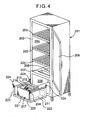
- FIG. 4 Such a refrigeration device discloses all the known features of the refrigerated cabinet having a cooling chamber discussed above.
- reference numerals 201 denotes a main body constituted of a rectangular insulating box member 202 which opens in a front surface, a plurality of stages of shelves 203 are built in the insulating box member 202 and a storage chamber 204 as a space to be cooled is constituted on each shelf.
- the opening in the front surface is openably closed by a door 209 rotatably supported with respect to the front surface of the insulating box member 202 and constituted of a transparent wall through which the inside can be seen.
- a bottom surface of the main body 201 is provided with a suction port 207 and a discharge port 208 which communicate with the inside of a mechanical chamber 206 constituted in a lower part, air in the storage chamber 204 is sucked from the suction port 207 into the mechanical chamber 206 by a blower 216 and air which has exchanged heat with an evaporator 215 is supplied from the discharge port 208 into the storage chamber 204 by the blower 216.
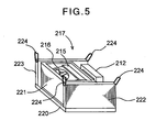
- a refrigerating unit 217 including a refrigerant circuit constituted of a compressor 211, a radiator 212, the evaporator 215 disposed separately from the compressor 211 and radiator 212 via an insulating wall 221, the blower 216 for ventilating the evaporator 215 and the like.
- a unit base 220 Figure 5 .
- Walls 222,223 each having hooks 224 on opposite ends are disposed on opposite sides of this unit base 220. These hooks 224 are engaged with attaching portions (not shown) formed in the bottom surface of the main body 201 and detachably constituted. That is, the whole refrigerating unit 217 disposed on the unit base 220 can be detachably attached to the bottom surface of the main body 201 via the hooks 224.
- the refrigerating unit 217 can be easily attached to the main body 201. Moreover, when the engagement is released, the refrigerating unit 217 can be easily separated from the main body 201. Therefore, repair or maintenance operability can be enhanced.
- the whole refrigerating unit 217 is attached to the main body 201 as described above, the whole refrigerating unit 217 is suspended in the main body 201. Therefore, since the main body 201 is loaded with considerable component weights, strength of the main body 201 needs to be increased. Since the whole refrigerating unit 217 has considerable component weights as described above, there has also occurred a problem that an assembly operability in attaching the refrigerating unit 217 to the main body 201 drops.
- the present invention has been developed to solve such conventional technical problem, and an object thereof is to improve an assembly operability while enhancing disconnecting and connecting properties of a main body and a refrigerating unit of a refrigerating device.
- a refrigerated cabinet according to the present invention is characterised in that the compressor and high pressure side heat exchanger are attached to a base member disposed on a lower surface of the component chamber and the low pressure side heat exchanger is coupled to the compressor and high pressure side heat exchanger by respective flexible tubes.
- FIG. 1 shows a perspective view of a case where a refrigerating device of the present invention is adapted to a showcase as one embodiment of the present invention
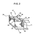
- FIG. 2 shows an enlarged view of a refrigerating unit 17 of the showcase, respectively.
- the refrigerating device of the present invention is usable in the showcase, an automatic dispenser, a refrigerator, a freezer and the like.
- reference numeral 1 denotes a main body of the showcase, and this main body 1 is constituted of a rectangular insulating box member 2 which opens in a front surface.
- a plurality of stages (three stages in the embodiment) of shelves 3 ... are built in the insulating box member 2, and a space on each shelf is constituted as a storage chamber 4 as a space to be cooled.
- the opening in the front surface is openably closed by a door 9 rotatably supported on a right front surface of the insulating box member 2 and constituted of a transparent wall through which the inside can be seen.
- a bottom surface of the main body 1 is provided with a suction port 7 and a discharge port 8 which communicate with the inside of a mechanical chamber 6 constituted under the bottom surface of the main body 1, air in the storage chamber 4 is sucked from the suction port 7 into a refrigerating box 25 of the mechanical chamber 6 by a blower 16 described later, and air which has exchanged heat with an evaporator 15 as a low-pressure-side heat exchanger is supplied from the discharge port 8 into the storage chamber 4 by the blower.
- the refrigerating unit 17 including a refrigerant circuit constituted of a compressor 11, a radiator 12 as a high-pressure-side heat exchanger, a fan 13 for supplying air to the radiator 12, the evaporator 15 and the like; and the blower 16 for supplying cold air which has exchanged the heat with the evaporator 15 to the storage chamber 4 constituted in the main body 1 to cool the chamber.
- the compressor 11, the radiator 12, and the fan 13 are disposed on a unit base 20 attached to the bottom surface of the mechanical chamber 6.
- the evaporator 15 and the blower 16 are stored in the refrigerating box 25 described above.
- This refrigerating box 25 is an insulating box member whose upper surface opens, and the evaporator 15 and the blower 16 are stored in the refrigerating box 25 as described above.
- a space 26 is disposed in the refrigerating box 25 on a side opposite to a side on which the blower 16 of the evaporator 15 is disposed, and an upper surface of this space 26 is formed in such a manner that the discharge port 8 described later is positioned.
- Hooks 24 ... are attached to corners of an upper part of the refrigerating box 25, respectively.
- the hooks 24 ... are formed so as to be engaged with attaching portions (not shown) formed in the bottom surface of the main body 1.
- attaching portions not shown
- the refrigerating box 25 can be detachably attached to the bottom surface of the main body 1 via the respective hooks 24 ...
- the suction port 7 is positioned in the upper surface of the blower 16 in the refrigerating box 25, and the discharge port 8 is positioned in the upper surface of the space 26 formed between the evaporator 15 in the refrigerating box 25 and the refrigerating box 25. That is, the inside of the storage chamber 4 communicates with the upper surface of the blower 16 in the refrigerating box 25 via the suction port 7. Therefore, the air in the storage chamber 4 can be sucked from the suction port 7 into the blower 16 in the refrigerating box 25.
- the inside of the storage chamber 4 communicates with the space 26 formed on the side of the evaporator 15 opposite to the blower 16 via the discharge port 8. Accordingly, the cold air sucked by the blower 16 to exchange the heat with the evaporator 15 can be supplied from the discharge port 8 into the storage chamber 4.
- the refrigerant circuit is constituted by connecting the compressor 11, the radiator 12, an expansion valve 14 as throttle means, the evaporator 15 and the like to one another in an annular form via pipes. That is, a refrigerant discharge pipe 34 of the compressor 11 is connected to an inlet of the radiator 12.
- the compressor 11 of the present embodiment is an inner intermediate pressure type 2-stage compression system rotary compressor, and the compressor is constituted of a driving element 44, and first and second rotary compression elements 50, 52 driven by the driving element 44 in a sealed container 11A.
- reference numeral 30 denotes a refrigerant introducing pipe for introducing a refrigerant into the first rotary compression element 50 of the compressor 11, and one end of this refrigerant introducing pipe 30 communicates with a cylinder (not shown) of the first rotary compression element 50.
- the other end of this refrigerant introducing pipe 30 is connected to an outlet side of the evaporator 15 stored in the refrigerating box 25.
- reference numeral 32 denotes a refrigerant introducing pipe for introducing the refrigerant compressed by the first rotary compression element 50 into the second rotary compression element 52.
- the refrigerant discharge pipe 34 is a refrigerant pipe for discharging the refrigerant compressed by the second rotary compression element 52 to the radiator 12.
- a refrigerant pipe 36 connected to an outlet side of the radiator 12 is connected to an inlet side of the evaporator 15 stored in the refrigerating box 25 via the expansion valve 14.
- the refrigerant introducing pipe 30 connected to the outlet side of the evaporator 15 is connected to the first rotary compression element 50 of the compressor 11.
- the refrigerant pipe 36 and the refrigerant introducing pipe 30 disposed between the compressor 11 or the radiator 12 installed on the unit base 20 and the evaporator 15 in the refrigerating box 25 are constituted of flexible tubes, respectively. That is, in the refrigerant circuit, the refrigerant pipe 36 which connects the radiator 12 installed on the unit base 20 to the evaporator 15 in the refrigerating box 25, and the refrigerant introducing pipe 30 which connects the evaporator 15 in the refrigerating box 25 to the compressor 11 installed on the unit base 20 are constituted of the flexible tubes having stretchability, resistant to vibration, and superior in durability.
- the pipes can be connected without being disconnected or damaged even in a case where the refrigerant pipe 36 and the refrigerant introducing pipe 30 are subjected to an stretching operation. Therefore, the refrigerating box 25 can be attached to the main body 1 without any trouble even in a case where the refrigerant circuit is pipe-connected.
- the refrigerating unit 17 pipe-connected beforehand and sealed with the refrigerant is constituted under the bottom surface of the main body 1 of the showcase, and set in the mechanical chamber 6. Moreover, the respective hooks 24 ... of the refrigerating box 25 are engaged with the attaching portions (not shown) formed in the bottom surface of the main body 1. Accordingly, the refrigerating box 25 is attached to the bottom surface of the main body 1, the inside of the storage chamber 4 communicates with the upper surface of the blower 16 in the refrigerating box 25 via the suction port 7, and the inside of the storage chamber 4 communicates with the space 26 in the refrigerating box 25 via the discharge port 8.
- the refrigerant discharged into the sealed container 11A is once discharged from the refrigerant introducing pipe 32 to the outside of the sealed container 11A, the refrigerant is sucked into the second rotary compression element 52 and compressed to form a high-temperature high-pressure refrigerant gas, and the gas is discharged from the refrigerant discharge pipe 34 to the outside of the compressor 11.
- the high-temperature high-pressure refrigerant gas discharged to the outside of the compressor 11 flows from the refrigerant discharge pipe 34 into the radiator 12, and is subjected to ventilation by the fan 13 to radiate the heat there. Moreover, the refrigerant flows out of the radiator 12 to enter the refrigerant pipe 36, and reaches the expansion valve 14. A pressure of the refrigerant drops in the expansion valve 14, and the refrigerant in this state flows into the evaporator 15 stored in the refrigerating box 25. There the refrigerant evaporates, and exerts a cooling function by heat absorption from a surrounding area.
- the air in the storage chamber 4 is sucked from the suction port 7 into the refrigerating box 25, and supplied to the evaporator 15 by means of the operation of the blower 16.
- the air is cooled by the evaporation of the refrigerant, and the cooled air (cold air) is supplied from the space 26 into the storage chamber 4 via the discharge port 8.
- the air is circulated in the storage chamber 4 to cool the inside of the storage chamber 4.
- the evaporator 15 and the blower 16 are stored in the refrigerating box 25 having an insulating property, heat generated by the operation of the compressor 11, or air heated by heat exchange with the radiator 12 can be interrupted by the refrigerating box 25. Consequently, since the cold air that has exchanged the heat with the evaporator 15 can be supplied into the storage chamber 4 without being heated, a cooling efficiency can be enhanced.
- the refrigerant evaporated in the evaporator 15 flows out of the evaporator 15 to enter the refrigerant introducing pipe 30, and is sucked into the first rotary compression element 50 of the compressor 11. This cycle is repeated.
- a disconnecting method will be described in a case where some trouble is generated in the refrigerating unit 17, or the refrigerating unit 17 is subjected to maintenance.
- a stop switch (not shown) disposed in the main body 1, or extracts the power socket from the outlet, the operation of the compressor 11 stops.
- the refrigerating unit 17 can be removed.
- the mechanical chamber 6 is constituted under the bottom surface of the main body 1, and the compressor 11 and the radiator 12 are installed on the unit base 20 on the bottom surface of the mechanical chamber 6.
- the refrigerating box 25 in which the evaporator 15 and the blower 16 are stored is detachably attached to the bottom surface of the main body 1 via the hooks 24 ... in such a manner that the refrigerating box communicates with the inside of the storage chamber 4 via the suction port 7 and the discharge port 8. Consequently, an operation to attach the refrigerating box 25 to the main body 1 can be more easily performed. Since the refrigerating box 25 can be detached at a trouble time or a maintenance time, such trouble can be quickly handled, and a maintenance managing operation can be easily performed.
- the refrigerating box 25, and the evaporator 15 and blower 16 stored in the refrigerating box 25 are attached to the bottom part of the main body 1, weights of the components attached to the bottom surface of the main body 1 can be reduced.
- the refrigerant pipe 36 and refrigerant introducing pipe 30 disposed between the compressor 11 or the radiator 12 on the unit base 20 and the evaporator 15 inside the refrigerating box 25 are constituted of the flexible tubes, the refrigerating box 25 can be attached to the main body 1 without any trouble even in a state in which the refrigerant circuit is pipe-connected.
- the inner intermediate pressure type 2-stage compression system rotary compressor is used as the compressor, but a compressor usable in the present invention is not limited to this compressor, another compressor system or a single-stage or three or more stages of compression elements may be provided.
Landscapes
- Engineering & Computer Science (AREA)
- Chemical & Material Sciences (AREA)
- Combustion & Propulsion (AREA)
- Physics & Mathematics (AREA)
- Mechanical Engineering (AREA)
- Thermal Sciences (AREA)
- General Engineering & Computer Science (AREA)
- Devices That Are Associated With Refrigeration Equipment (AREA)
- Freezers Or Refrigerated Showcases (AREA)
- Encapsulation Of And Coatings For Semiconductor Or Solid State Devices (AREA)
- Sampling And Sample Adjustment (AREA)
- Surgical Instruments (AREA)
Claims (1)
- Kühlschrank mit einer Kühlkammer (4) und einer Komponentenkammer, die von der Kühlkammer (4) mittels einer Abtrennwand abgeteilt ist, um darin einen Kompressor (11), hoch- und niederdruckseitige Wärmetauscher (12, 15) sowie ein Gebläse (13) eines Kühlkreislaufes aufzunehmen, wobei die Abtrennwand darin eine Öffnung (7, 8) hat, um eine Luftströmung zwischen den Kammern (4, 6) zu ermöglichen, sowie darin ein Behälter (25) vorgesehen ist, der abnehmbar an der Abtrennwand an der Öffnung (7, 8) aufgehängt ist, und in dem der niederdruckseitige Wärmetauscher (15) und das Gebläse (13) angeordnet ist, dadurch gekennzeichnet, dass der Kompressor (11) und der hochdruckseitige Wärmetauscher (12) an einem Basiselement (20) angebracht sind, welches an einer unteren Oberfläche der Komponentenkammer (6) angeordnet ist, sowie der niederdruckseitige Wärmetauscher (15) mit dem Kompressor (11) und dem hochdruckseitigen Wärmetauscher (12) mittels jeweils flexibler Leitungen (30, 26) verbunden ist.
Applications Claiming Priority (1)
| Application Number | Priority Date | Filing Date | Title |
|---|---|---|---|
| JP2004353839A JP4660176B2 (ja) | 2004-12-07 | 2004-12-07 | 冷却装置 |
Publications (3)
| Publication Number | Publication Date |
|---|---|
| EP1669707A2 EP1669707A2 (de) | 2006-06-14 |
| EP1669707A3 EP1669707A3 (de) | 2006-07-19 |
| EP1669707B1 true EP1669707B1 (de) | 2008-08-13 |
Family
ID=35985287
Family Applications (1)
| Application Number | Title | Priority Date | Filing Date |
|---|---|---|---|
| EP05110665A Not-in-force EP1669707B1 (de) | 2004-12-07 | 2005-11-11 | Kühleinrichtung |
Country Status (8)
| Country | Link |
|---|---|
| US (1) | US8424332B2 (de) |
| EP (1) | EP1669707B1 (de) |
| JP (1) | JP4660176B2 (de) |
| KR (1) | KR101160360B1 (de) |
| CN (1) | CN100533014C (de) |
| AT (1) | ATE404833T1 (de) |
| DE (1) | DE602005008874D1 (de) |
| TW (1) | TW200619580A (de) |
Cited By (1)
| Publication number | Priority date | Publication date | Assignee | Title |
|---|---|---|---|---|
| EP3919844A1 (de) | 2020-06-04 | 2021-12-08 | PremiumWineTech GmbH | Kühlmöbel und verfahren zum kühlen von kühlgut |
Families Citing this family (27)
| Publication number | Priority date | Publication date | Assignee | Title |
|---|---|---|---|---|
| JP4859562B2 (ja) * | 2006-07-06 | 2012-01-25 | サンデン株式会社 | 冷却庫 |
| WO2008013546A1 (en) * | 2006-07-28 | 2008-01-31 | Carrier Corporation | Refrigerated display merchandiser with microchannel evaporator oriented to reliably remove condensate |
| ITMI20072106A1 (it) * | 2007-10-31 | 2009-05-01 | Bravo Spa | Impianto frigorifero |
| AU2009250077B2 (en) * | 2008-05-23 | 2012-11-01 | Aktiebolaget Electrolux | Cold appliance |
| DE102009006772A1 (de) * | 2009-01-30 | 2010-08-05 | Blanco Cs Gmbh + Co Kg | Temperaturkonditioniervorrichtung für einen Speisentransportbehälter |
| DE102009002034A1 (de) * | 2009-03-31 | 2010-10-07 | BSH Bosch und Siemens Hausgeräte GmbH | Haushaltskältegerät und Kältevorrichtung für ein Haushaltskältegerät |
| CN101999810A (zh) * | 2009-09-02 | 2011-04-06 | 上海海立中野冷机有限公司 | 一种分体组合式陈列冷柜 |
| US8522565B1 (en) * | 2009-10-20 | 2013-09-03 | The Veracity Group, Inc. | Refrigerator with removable cooling unit |
| ITTO20100489A1 (it) * | 2010-06-09 | 2011-12-10 | Indesit Co Spa | Apparecchio elettrodomestico |
| US20120023983A1 (en) * | 2010-08-02 | 2012-02-02 | Sg Beverage Solutions, Inc. | Removable refrigeration unit |
| US9532661B2 (en) | 2011-06-30 | 2017-01-03 | Pepsico, Inc. | Modular refrigerated merchandise display system |
| US9532660B2 (en) | 2011-06-30 | 2017-01-03 | Pepsico, Inc. | Refrigerated merchandise display system |
| CN102564012A (zh) * | 2012-01-19 | 2012-07-11 | 海尔集团公司 | 侧面安装的集成制冷装置 |
| CN103544773A (zh) * | 2012-07-16 | 2014-01-29 | 鸿富锦精密工业(武汉)有限公司 | 自动售货机中的温度调节装置 |
| WO2014121190A1 (en) | 2013-02-04 | 2014-08-07 | Metro Industries Inc. | Mobile refrigeration cabinet |
| US20140345316A1 (en) * | 2013-05-22 | 2014-11-27 | The Coca-Cola Company | Systems and methods for a modular cooler assembly |
| CN103471314B (zh) * | 2013-09-30 | 2016-07-27 | 合肥晶弘电器有限公司 | 一种可分离式冰箱 |
| GB201320569D0 (en) * | 2013-11-21 | 2014-01-08 | Ocado Ltd | Multi-compartment locker with removable environmental control unit |
| WO2018222645A1 (en) | 2017-05-31 | 2018-12-06 | Carrier Corporation | Actively cooled device for small scale delivery |
| KR102004047B1 (ko) * | 2017-10-23 | 2019-07-25 | 엘지전자 주식회사 | 컴팩트 기계실을 위한 제상수 받이 및 이를 적용한 냉장고 |
| DE102017221904A1 (de) * | 2017-12-05 | 2019-06-06 | BSH Hausgeräte GmbH | Haushaltsgerätevorrichtung |
| CN108224834A (zh) * | 2017-12-26 | 2018-06-29 | 宁波华斯特林电机制造有限公司 | 一种制冷模块以及使用该制冷模块的制冷设备 |
| JP6677267B2 (ja) * | 2018-03-30 | 2020-04-08 | ダイキン工業株式会社 | 冷凍サイクル装置 |
| CN110553452A (zh) * | 2018-06-04 | 2019-12-10 | 青岛海尔股份有限公司 | 冰箱 |
| CN113074502A (zh) * | 2020-01-06 | 2021-07-06 | 青岛海尔电冰箱有限公司 | 制冷模组及冰箱 |
| US11892226B2 (en) | 2021-12-10 | 2024-02-06 | Whirlpool Corporation | Refrigeration unit and method of assembling |
| JP2024043755A (ja) * | 2022-09-20 | 2024-04-02 | アクア株式会社 | パネル式冷蔵庫 |
Family Cites Families (20)
| Publication number | Priority date | Publication date | Assignee | Title |
|---|---|---|---|---|
| JPS5650984U (de) * | 1979-09-26 | 1981-05-06 | ||
| JPH0623900Y2 (ja) * | 1989-07-31 | 1994-06-22 | ホシザキ電機株式会社 | 冷蔵装置の断熱構造 |
| US4977754A (en) * | 1990-05-01 | 1990-12-18 | Specialty Equipment Companies, Inc. | Next-to-be-purchased cold beverage merchandiser |
| US5347827A (en) * | 1992-07-01 | 1994-09-20 | The Coca-Cola Company | Modular refrigeration apparatus |
| JP3022121B2 (ja) * | 1993-12-28 | 2000-03-15 | 三洋電機株式会社 | 低温ショーケース |
| ES2115433B1 (es) * | 1994-03-29 | 1999-02-16 | Guillen Ramon Torres | Disposicion para refrigerar productos almacenados en el armario de una maquina expendedora. |
| JPH08121932A (ja) * | 1994-10-20 | 1996-05-17 | Toyo Eng Works Ltd | 局所冷却装置 |
| JPH08313138A (ja) * | 1995-05-17 | 1996-11-29 | G Ee Shi Kk | 卓上型冷却装置 |
| JP3675910B2 (ja) * | 1995-10-02 | 2005-07-27 | 三洋電機株式会社 | 冷却貯蔵庫 |
| JP2000105060A (ja) | 1998-09-30 | 2000-04-11 | Sanyo Electric Co Ltd | ショーケースの温度表示装置 |
| JP2000105058A (ja) * | 1998-09-30 | 2000-04-11 | Sanyo Electric Co Ltd | 冷却貯蔵庫 |
| JP2001351162A (ja) * | 2000-06-08 | 2001-12-21 | Shibaura Mechatronics Corp | 自動販売機 |
| US6550255B2 (en) * | 2001-03-21 | 2003-04-22 | The Coca-Cola Company | Stirling refrigeration system with a thermosiphon heat exchanger |
| JP4493230B2 (ja) * | 2001-03-28 | 2010-06-30 | 三洋電機株式会社 | 冷却貯蔵庫 |
| BR0106589B1 (pt) * | 2001-12-27 | 2009-05-05 | sistema de refrigeraçáo com condensador tipo placa e método para compactá-lo. | |
| KR100896264B1 (ko) * | 2003-01-17 | 2009-05-08 | 삼성전자주식회사 | 냉장고 및 냉각장치 |
| TWI325949B (en) * | 2004-02-09 | 2010-06-11 | Sanyo Electric Co | Refrigerant system |
| JP4190451B2 (ja) * | 2004-03-31 | 2008-12-03 | 三洋電機株式会社 | 冷却貯蔵庫 |
| JP4190461B2 (ja) * | 2004-05-27 | 2008-12-03 | 三洋電機株式会社 | 冷却貯蔵庫 |
| JP4493478B2 (ja) * | 2004-11-25 | 2010-06-30 | 三洋電機株式会社 | 冷却貯蔵庫 |
-
2004
- 2004-12-07 JP JP2004353839A patent/JP4660176B2/ja not_active Expired - Fee Related
-
2005
- 2005-09-27 TW TW094133474A patent/TW200619580A/zh not_active IP Right Cessation
- 2005-11-10 CN CNB2005101158757A patent/CN100533014C/zh not_active Expired - Fee Related
- 2005-11-11 DE DE602005008874T patent/DE602005008874D1/de active Active
- 2005-11-11 AT AT05110665T patent/ATE404833T1/de not_active IP Right Cessation
- 2005-11-11 EP EP05110665A patent/EP1669707B1/de not_active Not-in-force
- 2005-12-02 US US11/291,778 patent/US8424332B2/en not_active Expired - Fee Related
- 2005-12-07 KR KR1020050118910A patent/KR101160360B1/ko not_active IP Right Cessation
Cited By (2)
| Publication number | Priority date | Publication date | Assignee | Title |
|---|---|---|---|---|
| EP3919844A1 (de) | 2020-06-04 | 2021-12-08 | PremiumWineTech GmbH | Kühlmöbel und verfahren zum kühlen von kühlgut |
| DE102020114820A1 (de) | 2020-06-04 | 2021-12-09 | PremiumWineTech GmbH | Kühlmöbel und Verfahren zum Kühlen von Kühlgut |
Also Published As
| Publication number | Publication date |
|---|---|
| DE602005008874D1 (de) | 2008-09-25 |
| CN100533014C (zh) | 2009-08-26 |
| EP1669707A3 (de) | 2006-07-19 |
| US8424332B2 (en) | 2013-04-23 |
| KR20060063764A (ko) | 2006-06-12 |
| JP2006162148A (ja) | 2006-06-22 |
| EP1669707A2 (de) | 2006-06-14 |
| KR101160360B1 (ko) | 2012-06-26 |
| US20060117789A1 (en) | 2006-06-08 |
| ATE404833T1 (de) | 2008-08-15 |
| TW200619580A (en) | 2006-06-16 |
| JP4660176B2 (ja) | 2011-03-30 |
| TWI346763B (de) | 2011-08-11 |
| CN1786630A (zh) | 2006-06-14 |
Similar Documents
| Publication | Publication Date | Title |
|---|---|---|
| EP1669707B1 (de) | Kühleinrichtung | |
| KR100333600B1 (ko) | 캔틸레버 선반을 구비한 냉장고의 냉기공급 구조 | |
| EP1462744A2 (de) | Kühlschrank | |
| KR20030027367A (ko) | 냉장고 | |
| JP2005069671A (ja) | 冷蔵庫 | |
| KR20060041721A (ko) | 가열/냉각 시스템 | |
| CN111473548A (zh) | 冷凝机组 | |
| KR20020087682A (ko) | 냉장고의 냉기순환 시스템 | |
| KR100950846B1 (ko) | 냉동고 | |
| KR200443435Y1 (ko) | 냉각실을 갖는 쇼케이스 | |
| JP2000314580A (ja) | 冷凍冷蔵庫 | |
| CN212901780U (zh) | 空调室外机 | |
| JP2005037120A (ja) | 冷蔵庫 | |
| KR200458146Y1 (ko) | 냉동차량용 냉각장치 | |
| JP2005037121A (ja) | 冷蔵庫 | |
| KR100484661B1 (ko) | 내부용적이 증가된 냉장고 | |
| KR100451346B1 (ko) | 냉장고의 냉기 공급장치 | |
| KR100416704B1 (ko) | 직출형/덕트형 겸용 패키지 에어컨의 실내기 | |
| JP2944355B2 (ja) | 冷却装置 | |
| KR100763155B1 (ko) | 냉장고의 냉기공급장치 | |
| JP2002062028A (ja) | 冷蔵庫 | |
| JP2005164107A (ja) | 店舗用冷凍機 | |
| KR200190467Y1 (ko) | 공기조화기용실외기 | |
| KR20050020732A (ko) | 냉장고용 일체형 냉각시스템 | |
| KR200218967Y1 (ko) | 쇼케이스용 그릴 |
Legal Events
| Date | Code | Title | Description |
|---|---|---|---|
| PUAI | Public reference made under article 153(3) epc to a published international application that has entered the european phase |
Free format text: ORIGINAL CODE: 0009012 |
|
| AK | Designated contracting states |
Kind code of ref document: A2 Designated state(s): AT BE BG CH CY CZ DE DK EE ES FI FR GB GR HU IE IS IT LI LT LU LV MC NL PL PT RO SE SI SK TR |
|
| AX | Request for extension of the european patent |
Extension state: AL BA HR MK YU |
|
| PUAL | Search report despatched |
Free format text: ORIGINAL CODE: 0009013 |
|
| AK | Designated contracting states |
Kind code of ref document: A3 Designated state(s): AT BE BG CH CY CZ DE DK EE ES FI FR GB GR HU IE IS IT LI LT LU LV MC NL PL PT RO SE SI SK TR |
|
| AX | Request for extension of the european patent |
Extension state: AL BA HR MK YU |
|
| 17P | Request for examination filed |
Effective date: 20061018 |
|
| 17Q | First examination report despatched |
Effective date: 20061201 |
|
| AKX | Designation fees paid |
Designated state(s): AT BE BG CH CY CZ DE DK EE ES FI FR GB GR HU IE IS IT LI LT LU LV MC NL PL PT RO SE SI SK TR |
|
| GRAP | Despatch of communication of intention to grant a patent |
Free format text: ORIGINAL CODE: EPIDOSNIGR1 |
|
| GRAS | Grant fee paid |
Free format text: ORIGINAL CODE: EPIDOSNIGR3 |
|
| GRAA | (expected) grant |
Free format text: ORIGINAL CODE: 0009210 |
|
| AK | Designated contracting states |
Kind code of ref document: B1 Designated state(s): AT BE BG CH CY CZ DE DK EE ES FI FR GB GR HU IE IS IT LI LT LU LV MC NL PL PT RO SE SI SK TR |
|
| REG | Reference to a national code |
Ref country code: GB Ref legal event code: FG4D |
|
| REG | Reference to a national code |
Ref country code: CH Ref legal event code: EP |
|
| REG | Reference to a national code |
Ref country code: IE Ref legal event code: FG4D |
|
| REF | Corresponds to: |
Ref document number: 602005008874 Country of ref document: DE Date of ref document: 20080925 Kind code of ref document: P |
|
| PG25 | Lapsed in a contracting state [announced via postgrant information from national office to epo] |
Ref country code: NL Free format text: LAPSE BECAUSE OF FAILURE TO SUBMIT A TRANSLATION OF THE DESCRIPTION OR TO PAY THE FEE WITHIN THE PRESCRIBED TIME-LIMIT Effective date: 20080813 Ref country code: LT Free format text: LAPSE BECAUSE OF FAILURE TO SUBMIT A TRANSLATION OF THE DESCRIPTION OR TO PAY THE FEE WITHIN THE PRESCRIBED TIME-LIMIT Effective date: 20080813 Ref country code: IS Free format text: LAPSE BECAUSE OF FAILURE TO SUBMIT A TRANSLATION OF THE DESCRIPTION OR TO PAY THE FEE WITHIN THE PRESCRIBED TIME-LIMIT Effective date: 20081213 |
|
| PG25 | Lapsed in a contracting state [announced via postgrant information from national office to epo] |
Ref country code: SI Free format text: LAPSE BECAUSE OF FAILURE TO SUBMIT A TRANSLATION OF THE DESCRIPTION OR TO PAY THE FEE WITHIN THE PRESCRIBED TIME-LIMIT Effective date: 20080813 Ref country code: LV Free format text: LAPSE BECAUSE OF FAILURE TO SUBMIT A TRANSLATION OF THE DESCRIPTION OR TO PAY THE FEE WITHIN THE PRESCRIBED TIME-LIMIT Effective date: 20080813 Ref country code: FI Free format text: LAPSE BECAUSE OF FAILURE TO SUBMIT A TRANSLATION OF THE DESCRIPTION OR TO PAY THE FEE WITHIN THE PRESCRIBED TIME-LIMIT Effective date: 20080813 Ref country code: ES Free format text: LAPSE BECAUSE OF FAILURE TO SUBMIT A TRANSLATION OF THE DESCRIPTION OR TO PAY THE FEE WITHIN THE PRESCRIBED TIME-LIMIT Effective date: 20081124 Ref country code: AT Free format text: LAPSE BECAUSE OF FAILURE TO SUBMIT A TRANSLATION OF THE DESCRIPTION OR TO PAY THE FEE WITHIN THE PRESCRIBED TIME-LIMIT Effective date: 20080813 |
|
| PG25 | Lapsed in a contracting state [announced via postgrant information from national office to epo] |
Ref country code: BE Free format text: LAPSE BECAUSE OF FAILURE TO SUBMIT A TRANSLATION OF THE DESCRIPTION OR TO PAY THE FEE WITHIN THE PRESCRIBED TIME-LIMIT Effective date: 20080813 |
|
| PG25 | Lapsed in a contracting state [announced via postgrant information from national office to epo] |
Ref country code: DK Free format text: LAPSE BECAUSE OF FAILURE TO SUBMIT A TRANSLATION OF THE DESCRIPTION OR TO PAY THE FEE WITHIN THE PRESCRIBED TIME-LIMIT Effective date: 20080813 Ref country code: BG Free format text: LAPSE BECAUSE OF FAILURE TO SUBMIT A TRANSLATION OF THE DESCRIPTION OR TO PAY THE FEE WITHIN THE PRESCRIBED TIME-LIMIT Effective date: 20081113 |
|
| PG25 | Lapsed in a contracting state [announced via postgrant information from national office to epo] |
Ref country code: SK Free format text: LAPSE BECAUSE OF FAILURE TO SUBMIT A TRANSLATION OF THE DESCRIPTION OR TO PAY THE FEE WITHIN THE PRESCRIBED TIME-LIMIT Effective date: 20080813 Ref country code: RO Free format text: LAPSE BECAUSE OF FAILURE TO SUBMIT A TRANSLATION OF THE DESCRIPTION OR TO PAY THE FEE WITHIN THE PRESCRIBED TIME-LIMIT Effective date: 20080813 Ref country code: CZ Free format text: LAPSE BECAUSE OF FAILURE TO SUBMIT A TRANSLATION OF THE DESCRIPTION OR TO PAY THE FEE WITHIN THE PRESCRIBED TIME-LIMIT Effective date: 20080813 |
|
| PLBE | No opposition filed within time limit |
Free format text: ORIGINAL CODE: 0009261 |
|
| STAA | Information on the status of an ep patent application or granted ep patent |
Free format text: STATUS: NO OPPOSITION FILED WITHIN TIME LIMIT |
|
| PG25 | Lapsed in a contracting state [announced via postgrant information from national office to epo] |
Ref country code: MC Free format text: LAPSE BECAUSE OF NON-PAYMENT OF DUE FEES Effective date: 20081130 |
|
| 26N | No opposition filed |
Effective date: 20090514 |
|
| PG25 | Lapsed in a contracting state [announced via postgrant information from national office to epo] |
Ref country code: EE Free format text: LAPSE BECAUSE OF FAILURE TO SUBMIT A TRANSLATION OF THE DESCRIPTION OR TO PAY THE FEE WITHIN THE PRESCRIBED TIME-LIMIT Effective date: 20080813 |
|
| PG25 | Lapsed in a contracting state [announced via postgrant information from national office to epo] |
Ref country code: IE Free format text: LAPSE BECAUSE OF NON-PAYMENT OF DUE FEES Effective date: 20081111 |
|
| PG25 | Lapsed in a contracting state [announced via postgrant information from national office to epo] |
Ref country code: SE Free format text: LAPSE BECAUSE OF FAILURE TO SUBMIT A TRANSLATION OF THE DESCRIPTION OR TO PAY THE FEE WITHIN THE PRESCRIBED TIME-LIMIT Effective date: 20081113 |
|
| PG25 | Lapsed in a contracting state [announced via postgrant information from national office to epo] |
Ref country code: PL Free format text: LAPSE BECAUSE OF FAILURE TO SUBMIT A TRANSLATION OF THE DESCRIPTION OR TO PAY THE FEE WITHIN THE PRESCRIBED TIME-LIMIT Effective date: 20080813 |
|
| REG | Reference to a national code |
Ref country code: CH Ref legal event code: PL |
|
| PG25 | Lapsed in a contracting state [announced via postgrant information from national office to epo] |
Ref country code: LU Free format text: LAPSE BECAUSE OF NON-PAYMENT OF DUE FEES Effective date: 20081111 Ref country code: HU Free format text: LAPSE BECAUSE OF FAILURE TO SUBMIT A TRANSLATION OF THE DESCRIPTION OR TO PAY THE FEE WITHIN THE PRESCRIBED TIME-LIMIT Effective date: 20090214 Ref country code: CY Free format text: LAPSE BECAUSE OF FAILURE TO SUBMIT A TRANSLATION OF THE DESCRIPTION OR TO PAY THE FEE WITHIN THE PRESCRIBED TIME-LIMIT Effective date: 20080813 |
|
| PG25 | Lapsed in a contracting state [announced via postgrant information from national office to epo] |
Ref country code: TR Free format text: LAPSE BECAUSE OF FAILURE TO SUBMIT A TRANSLATION OF THE DESCRIPTION OR TO PAY THE FEE WITHIN THE PRESCRIBED TIME-LIMIT Effective date: 20080813 |
|
| PG25 | Lapsed in a contracting state [announced via postgrant information from national office to epo] |
Ref country code: LI Free format text: LAPSE BECAUSE OF NON-PAYMENT OF DUE FEES Effective date: 20091130 Ref country code: GR Free format text: LAPSE BECAUSE OF FAILURE TO SUBMIT A TRANSLATION OF THE DESCRIPTION OR TO PAY THE FEE WITHIN THE PRESCRIBED TIME-LIMIT Effective date: 20081114 Ref country code: CH Free format text: LAPSE BECAUSE OF NON-PAYMENT OF DUE FEES Effective date: 20091130 |
|
| PG25 | Lapsed in a contracting state [announced via postgrant information from national office to epo] |
Ref country code: PT Free format text: LAPSE BECAUSE OF FAILURE TO SUBMIT A TRANSLATION OF THE DESCRIPTION OR TO PAY THE FEE WITHIN THE PRESCRIBED TIME-LIMIT Effective date: 20080813 |
|
| REG | Reference to a national code |
Ref country code: DE Ref legal event code: R082 Ref document number: 602005008874 Country of ref document: DE Representative=s name: VENNER SHIPLEY LLP, GB Ref country code: DE Ref legal event code: R082 Ref document number: 602005008874 Country of ref document: DE |
|
| PGFP | Annual fee paid to national office [announced via postgrant information from national office to epo] |
Ref country code: GB Payment date: 20141105 Year of fee payment: 10 Ref country code: FR Payment date: 20141110 Year of fee payment: 10 |
|
| PGFP | Annual fee paid to national office [announced via postgrant information from national office to epo] |
Ref country code: IT Payment date: 20141111 Year of fee payment: 10 |
|
| PGFP | Annual fee paid to national office [announced via postgrant information from national office to epo] |
Ref country code: DE Payment date: 20151103 Year of fee payment: 11 |
|
| GBPC | Gb: european patent ceased through non-payment of renewal fee |
Effective date: 20151111 |
|
| PG25 | Lapsed in a contracting state [announced via postgrant information from national office to epo] |
Ref country code: IT Free format text: LAPSE BECAUSE OF NON-PAYMENT OF DUE FEES Effective date: 20151111 |
|
| REG | Reference to a national code |
Ref country code: FR Ref legal event code: ST Effective date: 20160729 |
|
| PG25 | Lapsed in a contracting state [announced via postgrant information from national office to epo] |
Ref country code: GB Free format text: LAPSE BECAUSE OF NON-PAYMENT OF DUE FEES Effective date: 20151111 |
|
| PG25 | Lapsed in a contracting state [announced via postgrant information from national office to epo] |
Ref country code: FR Free format text: LAPSE BECAUSE OF NON-PAYMENT OF DUE FEES Effective date: 20151130 |
|
| REG | Reference to a national code |
Ref country code: DE Ref legal event code: R119 Ref document number: 602005008874 Country of ref document: DE |
|
| PG25 | Lapsed in a contracting state [announced via postgrant information from national office to epo] |
Ref country code: DE Free format text: LAPSE BECAUSE OF NON-PAYMENT OF DUE FEES Effective date: 20170601 |