EP1664584B1 - Stossdämpfer mit verbessertem wärmeausdehnungsausgleich - Google Patents
Stossdämpfer mit verbessertem wärmeausdehnungsausgleich Download PDFInfo
- Publication number
- EP1664584B1 EP1664584B1 EP04784599.5A EP04784599A EP1664584B1 EP 1664584 B1 EP1664584 B1 EP 1664584B1 EP 04784599 A EP04784599 A EP 04784599A EP 1664584 B1 EP1664584 B1 EP 1664584B1
- Authority
- EP
- European Patent Office
- Prior art keywords
- shock absorber
- absorber according
- pressure tube
- cylinder end
- piston
- Prior art date
- Legal status (The legal status is an assumption and is not a legal conclusion. Google has not performed a legal analysis and makes no representation as to the accuracy of the status listed.)
- Expired - Lifetime
Links
- 239000006096 absorbing agent Substances 0.000 title claims description 58
- 230000035939 shock Effects 0.000 title claims description 58
- 238000007667 floating Methods 0.000 claims description 20
- 230000006835 compression Effects 0.000 claims description 18
- 238000007906 compression Methods 0.000 claims description 18
- 239000012530 fluid Substances 0.000 claims description 15
- 239000000463 material Substances 0.000 claims description 6
- 229910000831 Steel Inorganic materials 0.000 description 15
- 239000010959 steel Substances 0.000 description 15
- XAGFODPZIPBFFR-UHFFFAOYSA-N aluminium Chemical compound [Al] XAGFODPZIPBFFR-UHFFFAOYSA-N 0.000 description 12
- 229910052782 aluminium Inorganic materials 0.000 description 12
- 238000013016 damping Methods 0.000 description 5
- 239000000725 suspension Substances 0.000 description 3
- 230000000712 assembly Effects 0.000 description 2
- 238000000429 assembly Methods 0.000 description 2
- 238000000034 method Methods 0.000 description 2
- 230000002093 peripheral effect Effects 0.000 description 2
- 230000036316 preload Effects 0.000 description 2
- 238000007789 sealing Methods 0.000 description 2
- 230000004075 alteration Effects 0.000 description 1
- 238000010276 construction Methods 0.000 description 1
- 230000017525 heat dissipation Effects 0.000 description 1
- 230000004048 modification Effects 0.000 description 1
- 238000012986 modification Methods 0.000 description 1
- 230000002035 prolonged effect Effects 0.000 description 1
- 230000000717 retained effect Effects 0.000 description 1
Images


Classifications
-
- F—MECHANICAL ENGINEERING; LIGHTING; HEATING; WEAPONS; BLASTING
- F16—ENGINEERING ELEMENTS AND UNITS; GENERAL MEASURES FOR PRODUCING AND MAINTAINING EFFECTIVE FUNCTIONING OF MACHINES OR INSTALLATIONS; THERMAL INSULATION IN GENERAL
- F16F—SPRINGS; SHOCK-ABSORBERS; MEANS FOR DAMPING VIBRATION
- F16F9/00—Springs, vibration-dampers, shock-absorbers, or similarly-constructed movement-dampers using a fluid or the equivalent as damping medium
- F16F9/06—Springs, vibration-dampers, shock-absorbers, or similarly-constructed movement-dampers using a fluid or the equivalent as damping medium using both gas and liquid
- F16F9/062—Bi-tubular units
-
- F—MECHANICAL ENGINEERING; LIGHTING; HEATING; WEAPONS; BLASTING
- F16—ENGINEERING ELEMENTS AND UNITS; GENERAL MEASURES FOR PRODUCING AND MAINTAINING EFFECTIVE FUNCTIONING OF MACHINES OR INSTALLATIONS; THERMAL INSULATION IN GENERAL
- F16F—SPRINGS; SHOCK-ABSORBERS; MEANS FOR DAMPING VIBRATION
- F16F9/00—Springs, vibration-dampers, shock-absorbers, or similarly-constructed movement-dampers using a fluid or the equivalent as damping medium
- F16F9/32—Details
- F16F9/3207—Constructional features
- F16F9/3235—Constructional features of cylinders
- F16F9/3242—Constructional features of cylinders of cylinder ends, e.g. caps
-
- F—MECHANICAL ENGINEERING; LIGHTING; HEATING; WEAPONS; BLASTING
- F16—ENGINEERING ELEMENTS AND UNITS; GENERAL MEASURES FOR PRODUCING AND MAINTAINING EFFECTIVE FUNCTIONING OF MACHINES OR INSTALLATIONS; THERMAL INSULATION IN GENERAL
- F16F—SPRINGS; SHOCK-ABSORBERS; MEANS FOR DAMPING VIBRATION
- F16F9/00—Springs, vibration-dampers, shock-absorbers, or similarly-constructed movement-dampers using a fluid or the equivalent as damping medium
- F16F9/32—Details
- F16F9/36—Special sealings, including sealings or guides for piston-rods
- F16F9/366—Special sealings, including sealings or guides for piston-rods functioning as guide only, e.g. bushings
-
- F—MECHANICAL ENGINEERING; LIGHTING; HEATING; WEAPONS; BLASTING
- F16—ENGINEERING ELEMENTS AND UNITS; GENERAL MEASURES FOR PRODUCING AND MAINTAINING EFFECTIVE FUNCTIONING OF MACHINES OR INSTALLATIONS; THERMAL INSULATION IN GENERAL
- F16F—SPRINGS; SHOCK-ABSORBERS; MEANS FOR DAMPING VIBRATION
- F16F9/00—Springs, vibration-dampers, shock-absorbers, or similarly-constructed movement-dampers using a fluid or the equivalent as damping medium
- F16F9/32—Details
- F16F9/50—Special means providing automatic damping adjustment, i.e. self-adjustment of damping by particular sliding movements of a valve element, other than flexions or displacement of valve discs; Special means providing self-adjustment of spring characteristics
- F16F9/52—Special means providing automatic damping adjustment, i.e. self-adjustment of damping by particular sliding movements of a valve element, other than flexions or displacement of valve discs; Special means providing self-adjustment of spring characteristics in case of change of temperature
Definitions
- Hydraulic dampers such as shock absorbers
- shock absorbers are used in connection with motor vehicle suspension systems to absorb unwanted vibrations which occur during the operation of the motor vehicle.
- the unwanted vibrations are dampened by shock absorbers which are generally connected between the sprung portion (i.e., the vehicle body) and the unsprung portion (i.e., the suspension) of the motor vehicle.
- a piston assembly is located within the compression chamber of the shock absorber and is usually connected to the body of the motor vehicle through a piston rod.
- the piston assembly includes a valving arrangement that is able to limit the flow of damping fluid within the compression chamber when the shock absorber is compressed or extended. As such, the shock absorber is able to generate a damping force which "smooths" or “dampens" the vibrations transmitted between the suspension and the vehicle body.
- Shock absorber 100 comprises an elongated pressure tube 102 provided for defining a hydraulic fluid containing compression chamber 104 and an elongated reserve tube 106 provided for defining a hydraulic fluid containing reservoir 108.
- a reciprocal piston assembly 110 Disposed within compression chamber 104 is a reciprocal piston assembly 110 that is secured to one end of an axially extending piston rod 112. Piston rod 112 is supported and guided for movement within pressure tube 102 by means of a combination seal and rod guide assembly 114 located at the upper end of pressure tube 102 and having a centrally extending bore 116 through which piston rod 112 is reciprocally movable. Disposed within bore 116 between rod guide assembly 114 and piston rod 112 is a busing 118 which is used to facilitate movement of piston rod 112 with respect to rode guide assembly 114.
- a compliant cylinder end assembly is located at the lower end of pressure tube 102.
- the compliant cylinder end assembly 120 includes a base valve assembly 122 that functions to control the flow of hydraulic fluid between compression chamber 104 and fluid reservoir 108 as well as biasing member 124 that compensates for the differing axial thermal expansion between the various components of shock absorber 100.
- Fluid reservoir 108 is defined as the space between the outer peripheral surface of pressure tube 102 and the inner peripheral surface of reserve tube 106.
- shock absorber 100 The upper and lower ends of shock absorber 100 are adapted for assembly into a motor vehicle.
- Piston rod 112 is shown having a threaded portion 126 for securing the upper end of shock absorber 100 to the motor vehicle while reserve tube 106 is shown incorporating a flange 128 having a pair of mounting holes 130 for securing the lower end of shock absorber 100 to the motor vehicle (McPherson strut configuration).
- shock absorber 100 is shown in a McPherson strut configuration having threaded portion 126 and flange 128 for securing it between the sprung and unsprung portions of the motor vehicle, it is to be understood that this is merely exemplary in nature and is only intended to illustrate one type of system for securing shock absorber 100 to the motor vehicle.
- hydraulic fluid with compression chamber 104 will be transferred between an upper portion 132 and a lower portion 134 of compression chamber 104 as well as between compression chamber 104 and fluid reservoir 108 through valve assembly 122 for damping relative movement between the sprung portion and the unsprung portion of the motor vehicle.
- shock absorber 100 In addition to absorbing the heat generated while providing the damping function for the motor vehicle, shock absorber 100 is also required to operate over a broad range of temperatures ranging from severe cold temperatures of the winter months to the extremely hot temperatures of the summer months.
- Prior art shock absorbers are manufactured using steel for pressure tube 102 and reserve tube 106. While steel has been proven to be an acceptable material for these components, tubes manufactured from aluminum offer the advantages of weight savings as well as improved heat dissipation. If the typical pressure tube 102 were manufactured from steel while reservoir tube 106 were manufactured from aluminum, the difference in their relative axial thermal expansion rates may present problems for the shock absorber when operating over the necessary temperature extremes. Specifically, structural failure may occur under extreme cold temperatures or loss of pressure tube preload and sealing may occur under extreme hot temperatures.
- shock absorbers with aluminum tubes includes the further development of methods to compensate for differing thermal expansion between aluminum and steel as well as the differing thermal expansion between any other two materials.
- D1 discloses a double tube vibration damper comprising a pressure tube and a container tube. Two working chambers are defined by the piston within the pressure tube. A compensation space is provided between the pressure tube and the container tube. The pressure tube extends axially between a bottom wall of the container tube and a piston rod guide secured to the container tube. A spring is in series with the pressure tube between the bottom wall and the piston rod guide. This spring compensates for different length variations of the pressure tube and the container tube. This spring is always under compressional stress throughout the operational range of temperature.
- the present invention provides the art with a shock absorber which is capable of compensating for the differing thermal expansion between two materials and thus eliminating the possibility of structural failure due to extreme cold temperatures as well as the possibility of pressure tube preload loss and sealing failure under extreme hot temperatures.
- the shock absorber includes a free floating pressure tube that is capable of compensating for differing thermal expansion by freely moving between the rod guide assembly and the valve assembly.
- a unique piston rod in another embodiment, includes an aluminum rod that eliminates the difference in thermal expansions.
- the rod has a steel cap that absorbs compression forces.
- a unique compensating rod guide assembly in another embodiment, includes a thermal compensation element capable of compensating for the differing thermal expansion between the pressure tube and the reserve tube.
- a unique compensating cylinder end assembly that includes a thermal compensation element, and the means for securing the element to the valve assembly.
- This compensating element is either a spring, an elastomeric block, or gas pressure.
- shock absorber 100 is merely exemplary in nature and is only intended to illustrate one type of hydraulic damping apparatus within which the compensating elements of the present invention can be utilized.
- FIG. 2 a unique compensating shock absorber 200 having a floating pressure tube 202 and a base valve assembly 222.
- Rod guide assembly 114 and base valve assembly 222 are mechanically secured to reserve tube 106.
- reserve tube 106 As the relative length of reserve tube 106 changes due to thermal conditions, the relative distance between rod guide assembly 114 and base valve assembly 222 changes.
- pressure tube 102 is fixed at one end to one portion of rod guide assembly 114 and at the other end to base valve assembly 122, such that changes in the length of pressure tube 102 due to thermal conditions were compensated for using a multi-piece valve assembly 122.
- a floating pressure tube 202 replaces pressure tube 102 of the prior art in order to compensate for the different thermal expansions of reserve tube 106 and floating pressure tube 202.
- Floating pressure tube 202 is sealed to rod guide assembly 114 and base valve assembly 222 using O-rings 204.
- Floating pressure tube 202 is able to move freely between rod guide assembly 114 and base valve assembly 222 as the relative length of reserve tube 106 changes.
- both a standard valve guide assembly and a standard base valve assembly can be easily modified to accept floating pressure tube 202.
- a hybrid piston rod 312 replaces the prior art piston rod 112 as shown in Figures 3-5 .
- the prior art piston rod 112 is made from steel while rod guide assembly 114 is made from aluminum. Under extreme thermal conditions the seal between piston rod 112 and rod guide 114 can be broken by the different thermal expansion of the two materials.
- Hybrid piston rod 312 includes an aluminum piston shaft 314 and a steel piston post 316. As shown in Figure 4 , piston post 316 includes an internal bore 318 which slidingly receives the end of piston shaft 314. A circle-clip 320 retains the assembly of piston post 316 and piston shaft 316.
- piston post 316 has an open threaded bore 322 for receiving a threaded end of piston shaft 314. Piston post 316 may be threaded on to piston shaft 314.
- a modified steel piston post 330 with a flat end 332 may be adhesively secured to the end of piston shaft 314.
- aluminum piston shaft 314 expands and contracts at the same rate as aluminum rod guide assembly 114 and thus prevents a break in the seal between the two.
- Steel piston post 316, or alternately modified steel piston post 320 absorbs the axial force on piston rod 312 when shock absorber 100 is in compression.
- FIG. 6-9 various compensating piston rod guide assemblies are shown in Figures 6-9 .
- the compensating piston rod guide assembly 414 supports and guides the movement of piston rod 112 and also compensates for the different thermal expansion of pressure tube 102 and reserve tube 106.
- Compensating piston rod guide assembly 414 includes bore 116 and bushing 118, as well as a plurality, an even number in the preferred embodiment, of Belleville springs 424 disposed between rod guide 414 and pressure tube 102. The difference in thermal expansion between steel pressure tube 102 and aluminum reserve tube 106 is compensated for by the increase or decrease in the compensation of Belleville springs 424.
- Alternate piston rod guide 414' includes a bearing bush retainer 450 disposed between Belleville springs 424 and rod guide 414'.
- Bearing bush retainer 450 seals rod guide 414' and pressure tube 102 and retains bushing 118, and is further designed to support Belleville springs 424.
- the thermal expansion of pressure tube 102 is directly compensated for by Belleville springs 424.
- piston rod guide 414' is shown with bearing bush retainer 450 being replaced by compensation retainer 450'.
- Compensation retainer 450' functions the same as bearing bush retainer 450 in that it retains bushing 118 and it is designed to support Belleville springs 424.
- the thermal expansion is directly compensated for by Belleville springs 424.
- a compensating piston rod guide 414" is shown on the left side of Figure 8 , wherein bearing bush retainer 452 is disposed between the pressure tube 102 and Belleville springs 424.
- Bearing bush retainer 452 is similar to bearing bush retainer 450 in that it seals rod guide 414" and pressure tube 102 and it supports Belleville springs 424.
- the difference between bearing bush retainer 452 and 450 is that Belleville springs 424 are disposed between rod guide 414" and bearing bush 452 instead of between bearing bush retainer 450 and pressure tube 102 as shown in Figure 7 .
- the thermal expansion is directly compensated for by Belleville springs 424.
- piston rod guide 414" is shown with bearing bush retainer 452 being replaced by compensation retainer 452'.
- Compensation retainer 450' functions the same as bearing bush retainer 452' in that it retains bushing 118 and it is designed to support Belleville springs 424 with Belleville springs 424 being disposed between rod guide 414" and bush retainer 452'. The thermal expansion is directly compensated for by Belleville springs 424.
- a compensating piston rod guide 414"' is shown in Figure 9 , wherein bearing bush retainer 452 has been replaced by a compensation spring support 460.
- Spring support 460 acts to support Belleville springs 424 but it does not retain bushing 118.
- Belleville springs 424 are disposed between rod guide 414'" and spring support 460. The thermal expansion is directly compensated for by Belleville springs 424.
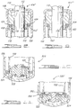
- FIG. 10 In yet further embodiments of prior art shock absorber 100, various compensating cylinder end assemblies are shown in Figures 10-19 .
- a compensating cylinder end assembly generally designated as 520, is located at the lower end of pressure tube 102 and functions to control the flow of hydraulic fluid between compression chamber 104 and fluid reservoir 108.
- Compensating end assembly 520 further acts to compensate for the differing axial thermal expansion between the various components of shock absorber 100.
- compensating cylinder end assembly 520 includes a base valve assembly 522 and a plurality, an even number in the preferred embodiment, of Belleville springs 524 disposed between pressure tube 102 and base valve assembly 522.
- the difference in thermal expansion between the steel pressure tube 102 and the aluminum reserve tube 106 is compensated for by the increase or decrease in the compression of Belleville springs 524.
- This embodiment differs from the prior art shown in Figure 1 by eliminating the need for the multi-piece base valve assembly 122 shown in Figure 1 .
- FIG. 11 Various methods for securing Belleville springs 524 to an end assembly are shown in Figures 11-14 .
- the compensating cylinder end assembly 520' includes a reaction ring 550.
- Reaction ring 550 is retained to the outside of pressure tube 102 by a circle-clip 552.
- Belleville springs 524 are disposed between ring 550 and compression valve assembly 522.
- a compensating cylinder end assembly 520" includes an S-shaped spring retainer 560.
- Spring retainer 560 is positioned between the bottom of pressure tube 102 and the top of Belleville springs 524, and acts to retain Belleville springs 524 between spring retainer 560 and valve assembly 522.
- the compensating cylinder end assembly 520"' includes a first retaining ring 570 and a second retaining ring 572.
- First retaining ring 570 is positioned such that it is in contact with the bottom of pressure tube 102.
- Second retaining ring 572 is secured to valve assembly 522.
- Belleville springs 524 are disposed between first retaining ring 570 and second retaining ring 572.
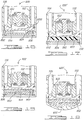
- an alternate compensating cylinder end base valve assembly is designated at 620.
- Compensating end base valve assembly 620 is divided into two portions, an upper portion 650 and a lower portion 652, and includes a plurality of Belleville springs 624 disposed between the two portions 650 and 652.
- Upper portion 650 is connected to pressure tube 102 and lower portion 652 is connected to or abuts reserve tube 106.
- Upper portion 650 fits within lower portion 652 and is sealed by an O-ring 654.
- Belleville springs 624 are disposed between the two portions 650, 652 and act to compensate for the different thermal expansion of pressure tube 102 and reserve tube 106 by moving upper portion 650 and lower portion 652 towards or away from each other.
- Cylinder end assembly 720 includes a base valve assembly 722 having a cylindrical wall 750 and a plurality of Belleville springs 724. Cylindrical wall 750 is connected to and surrounds a base valve assembly 722 and further extends towards the opposite end of shock absorber 100. Pressure tube 102 slides within cylindrical wall 750, and is sealed by an O-ring 752. Belleville springs 724 are disposed between pressure tube 102 and valve assembly 722 within cylindrical wall 750.
- compensating cylinder end assembly 820 is shown in Figure 16 .
- Compensating end assembly 820 includes a base valve assembly 822, a plurality of Belleville springs 824, a base plate 850, an O-ring 852, and a bottom retainer 854.
- Base plate 850 is capable of moving axially and is sealed to reserve tube 106 by O-ring 852.
- Bottom retainer 854 is fixed to reserve tube 106 using a retaining ring 856 and provides a flat, stable bottom for cylinder end assembly 820.
- Belleville springs 824 are disposed between base plate 850 and bottom retainer 854.
- Belleville springs 824 act to compensate for the different thermal expansion of the various components of shock absorber 100 through base plate 850 and bottom retainer 854.
- Belleville springs 824 are replaced with an elastomeric block 860.
- Elastomeric block 860 is disposed between base plate 850 and bottom retainer 854 and compensates for the different thermal expansion of pressure tube 102 and reserve tube 106 by expanding or compressing as necessary.
- pressurized gas 950 for example compressed air
- bottom retainer 954 is sealed to reserve tube 106 by a weld 956 or other means known in the art such that the gas 950 remains pressurized.
- Pressurized gas 950 compensates for the different thermal expansion of pressure tube 102 and reserve tube 106 by expanding or compressing as necessary, and also reduces the weight of the shock absorber.
- bottom retainer 954 has been removed.
- Pressurized gas 950 is disposed between base plate 952 and reserve tube 106 and compensates directly for the different thermal expansion of the pressure tube 102 and the reserve tube 106.
Landscapes
- Engineering & Computer Science (AREA)
- General Engineering & Computer Science (AREA)
- Mechanical Engineering (AREA)
- Fluid-Damping Devices (AREA)
Claims (23)
- Stoßdämpfer (200), der Wärmeausdehnung ausgleicht und eine Kompressionskammer (104), einen Stangenführungsaufbau (114), einen Kolben (110), der gleitend in der Kompressionskammer angeordnet ist, und eine Kolbenstange (112), die mit dem Kolben, einem Reserverohr (106) und einem Zylinderendaufbau (120) verbunden ist, umfasst,
dadurch gekennzeichnet, dass
der Stoßdämpfer ferner ein Gleitdruckrohr (202) umfasst, das die Kompressionskammer bildet, wobei das Gleitdruckrohr den Stangenführungsaufbau gleitend in Eingriff nimmt;
das Reserverohr um das Gleitdruckrohr (202) herum angeordnet ist, wobei das Reserverohr und das Gleitdruckrohr einen Fluidbehälter (108) definieren;
der Zylinderendaufbau (120) zwischen der Kompressionskammer und dem Fluidbehälter angeordnet ist, um den Fluidstrom zwischen der Kompressionskammer und dem Fluidbehälter zu steuern, wobei das Gleitdruckrohr den Zylinderendaufbau gleitend in Eingriff nimmt; und ein erstes Vorspannelement (424) zwischen dem Gleitdruckrohr und dem Stangenführungsaufbau angeordnet ist, um das Gleitdruckrohr axial von dem Stangenführungsaufbau wegzudrängen;
das Druckrohr sich in Bezug auf den Stangenführungsaufbau und den Zylinderendaufbau frei bewegen kann. - Stoßdämpfer nach Anspruch 1, wobei die Kolbenstange Folgendes umfasst:eine zweiteilige Kolbenstange (312), die mit dem Kolben verbunden ist, wobei die zweiteilige Kolbenstange eine Welle (314) und einen Kolbenzapfen (316) aufweist, wobei der Kolbenzapfen an dem Kolben (110) befestigt ist.
- Stoßdämpfer nach Anspruch 2, wobei die Welle aus einem ersten Material hergestellt ist und der Kolbenzapfen aus einem zweiten Material hergestellt ist.
- Stoßdämpfer nach Anspruch 3, wobei der Kolbenzapfen (316) so mit einem Gewinde versehen ist, dass er auf die Welle (314) aufschraubbar ist.
- Stoßdämpfer nach Anspruch 3, wobei der Kolbenzapfen (316) an die Welle (314) gebondet ist.
- Stoßdämpfer nach Anspruch 3, wobei der Kolbenzapfen (316) mittels einer Kreisklemme (320) an der Welle befestigt ist.
- Stoßdämpfer nach Anspruch 1, wobei das erste Vorspannelement mindestens eine Belleville-Feder (414) ist.
- Stoßdämpfer nach Anspruch 1, wobei eine Halterung (450) zwischen dem Stangenführungsaufbau und dem ersten Vorspannelement angeordnet ist.
- Stoßdämpfer nach Anspruch 1, wobei eine Halterung (452) zum Stützen des ersten Vorspannelements zwischen dem ersten Vorspannelement und dem Gleitdruckrohr angeordnet ist.
- Stoßdämpfer nach Anspruch 1, wobei der Stangenführungsaufbau ferner eine Buchse (118) aufweist, um die Bewegung der Kolbenstange zu erleichtern.
- Stoßdämpfer nach Anspruch 10, wobei eine Halterung (450) die Buchse hält.
- Stoßdämpfer nach Anspruch 1, der ferner Folgendes umfasst:ein zweites Vorspannelement (542), das zwischen dem Gleitdruckrohr (202) und dem Zylinderendaufbau angeordnet ist, um das Gleitdruckrohr von dem Zylinderendaufbau (120) wegzudrängen.
- Stoßdämpfer nach Anspruch 12, wobei das zweite Vorspannmittel eine Belleville-Feder ist.
- Stoßdämpfer nach Anspruch 13, wobei die Belleville-Feder mittels einer Kreisklemme (552) an dem Zylinderendaufbau befestigt ist.
- Stoßdämpfer nach Anspruch 13, wobei die Feder mittels einer Federhalterung (560) an dem Zylinderendaufbau befestigt ist.
- Stoßdämpfer nach Anspruch 13, wobei die Feder zwischen zwei radialen Halterungen (570, 572), die an dem Zylinderendaufbau befestigt sind, angeordnet ist.
- Stoßdämpfer nach Anspruch 12, wobei der Zylinderendaufbau zwei Abschnitte hat, einen oberen Abschnitt (650), der mit dem Gleitdruckrohr verbunden ist, und einen unteren Abschnitt (652), der mit dem Reserverohr verbunden ist, wobei der obere Abschnitt den unteren Abschnitt gleitend in Eingriff nimmt.
- Stoßdämpfer nach Anspruch 17, wobei das zweite Vorspannelement (524) zwischen dem oberen Abschnitt (650) und dem unteren Abschnitt (652) angeordnet ist.
- Stoßdämpfer nach Anspruch 12, wobei das zweite Vorspannelement und ein Ende des Gleitdruckrohrs in dem Zylinderendaufbau angeordnet sind.
- Stoßdämpfer nach Anspruch 1, der ferner Folgendes umfasst:eine Basisplatte (850), die das Reserverohr (106) angrenzend an den Zylinderendaufbau gleitend in Eingriff nimmt; undein zweites Vorspannelement (824), das zwischen der Basisplatte und einem Ende des Reserverohrs angeordnet ist, um die Basisplatte von dem Ende des Reserverohrs wegzudrängen.
- Stoßdämpfer nach Anspruch 20, wobei das zweite Vorspannelement eine Belleville-Feder (824) ist.
- Stoßdämpfer nach Anspruch 20, wobei das zweite Vorspannelement ein elastomerer Block (860) ist.
- Stoßdämpfer nach Anspruch 20, wobei das zweite Vorspannelement ein mit Druck beaufschlagtes Gas (950) ist.
Applications Claiming Priority (2)
| Application Number | Priority Date | Filing Date | Title |
|---|---|---|---|
| US10/671,354 US7004293B2 (en) | 2003-09-25 | 2003-09-25 | Thermal expansion compensation shock absorber |
| PCT/US2004/030783 WO2005030506A2 (en) | 2003-09-25 | 2004-09-21 | Improved thermal expansion compensation shock absorber |
Publications (3)
| Publication Number | Publication Date |
|---|---|
| EP1664584A2 EP1664584A2 (de) | 2006-06-07 |
| EP1664584A4 EP1664584A4 (de) | 2009-09-30 |
| EP1664584B1 true EP1664584B1 (de) | 2018-01-03 |
Family
ID=34376121
Family Applications (1)
| Application Number | Title | Priority Date | Filing Date |
|---|---|---|---|
| EP04784599.5A Expired - Lifetime EP1664584B1 (de) | 2003-09-25 | 2004-09-21 | Stossdämpfer mit verbessertem wärmeausdehnungsausgleich |
Country Status (5)
| Country | Link |
|---|---|
| US (2) | US7004293B2 (de) |
| EP (1) | EP1664584B1 (de) |
| CN (1) | CN100476234C (de) |
| BR (1) | BRPI0414797A (de) |
| WO (1) | WO2005030506A2 (de) |
Families Citing this family (22)
| Publication number | Priority date | Publication date | Assignee | Title |
|---|---|---|---|---|
| US20060011433A1 (en) * | 2004-07-19 | 2006-01-19 | Carlstedt Robert P | Damper valve body loading |
| JP2006064098A (ja) * | 2004-08-27 | 2006-03-09 | Kayaba Ind Co Ltd | フロントフォーク |
| CA2575089A1 (en) * | 2007-01-17 | 2008-07-17 | Mark Davis | Shock absorber |
| US8561768B2 (en) * | 2007-08-31 | 2013-10-22 | Honda Motor Co., Ltd. | Vehicle damper and method |
| US20100011681A1 (en) * | 2008-07-21 | 2010-01-21 | Wei-Hua Chiang | Shock Absorber |
| CN101793273B (zh) * | 2009-01-30 | 2017-05-17 | 日立汽车系统株式会社 | 缸装置 |
| JP5192438B2 (ja) * | 2009-04-28 | 2013-05-08 | カヤバ工業株式会社 | 複筒型液圧緩衝器 |
| EP2295693A1 (de) * | 2009-08-27 | 2011-03-16 | Joseph Talpe | Türschließmechanismus |
| US8128418B1 (en) | 2010-08-17 | 2012-03-06 | Hamilton Sundstrand Space Systems International, Inc. | Thermal expansion compensator having an elastic conductive element bonded to two facing surfaces |
| EP2633206B1 (de) | 2010-10-25 | 2019-07-17 | MSI Defense Solutions, LLC | Hydraulisches aufhängungssystem zur senkung der sitzhöhe eines fahrzeugs |
| DE102014202201A1 (de) | 2014-02-06 | 2015-08-06 | Zf Friedrichshafen Ag | Zweirohrschwingungsdämpfer |
| DE112015005306T5 (de) * | 2014-11-26 | 2017-08-24 | Tenneco Automotive Operating Company Inc. | Stossdämpfer, die eine basisanordnung aus verbundstoff mit ausgleich axialer flexibilität aufweisen |
| CN107206861B (zh) * | 2014-11-26 | 2019-09-06 | 天纳克汽车营运公司 | 具有带包覆模制的闭合插入件的复合基部组件的减振器 |
| CN104565174B (zh) * | 2014-12-23 | 2017-03-01 | 奇瑞商用车(安徽)有限公司 | 一种具有排气补偿结构的减振器 |
| DE102015212404A1 (de) * | 2015-07-02 | 2017-01-05 | Volkswagen Aktiengesellschaft | Hydraulischer Schwingungsdämpfer |
| CN113325523B (zh) * | 2016-04-01 | 2025-05-27 | Ipg光子公司 | 光纤电缆连接器 |
| DE102018220628B4 (de) | 2018-11-29 | 2022-08-18 | Thyssenkrupp Ag | Schwingungsdämpfer und Fahrzeug |
| WO2021087122A1 (en) | 2019-10-29 | 2021-05-06 | Ipg Photonics Corporation | Optical fiber cable connector |
| DE102019131319A1 (de) * | 2019-11-20 | 2021-05-20 | Thyssenkrupp Ag | Schwingungsdämpfer und Kraftfahrzeug mit einem solchen Schwingungsdämpfer |
| US11378150B1 (en) | 2021-01-12 | 2022-07-05 | Safran Landing Systems Canada Inc. | Temperature compensated shock absorber |
| US11794542B2 (en) | 2021-03-08 | 2023-10-24 | DRiV Automotive Inc. | Shock absorber with metal damper tube and composite mounting attachment and spring seat |
| CN113775688B (zh) * | 2021-08-27 | 2022-08-16 | 中国第一汽车股份有限公司 | 一种连续阻尼控制减振器 |
Family Cites Families (17)
| Publication number | Priority date | Publication date | Assignee | Title |
|---|---|---|---|---|
| DE2257557A1 (de) * | 1972-11-24 | 1974-06-06 | Fichtel & Sachs Ag | Entlueftungseinrichtung fuer zweirohrschwingungsdaempfer mittels einer starren scheibe |
| DE3873894T2 (de) * | 1987-12-14 | 1992-12-17 | Atsugi Motor Parts Co Ltd | Stossdaempfer mit aenderungen an der den kolben tragenden struktur. |
| DE3831719B4 (de) * | 1988-09-17 | 2011-06-01 | Zf Sachs Ag | Dichtung für eine axial beweglich in einem Behälter geführte Kolbenstange |
| CN2076937U (zh) * | 1990-05-18 | 1991-05-15 | 罗良祖 | 汽车减震器径向高载荷不漏油支承及油封装置 |
| DE4230238A1 (de) * | 1992-09-10 | 1994-03-17 | Fichtel & Sachs Ag | Zweirohrdämpfer |
| GB2287770B (en) * | 1994-03-21 | 1997-11-26 | Monroe Auto Equipment Co | Piston post for a damper |
| CN2198451Y (zh) * | 1994-07-08 | 1995-05-24 | 清华大学 | 汽车减振器衬套密封结构 |
| DE19512866C2 (de) * | 1995-04-06 | 1997-11-20 | Fichtel & Sachs Ag | Schwingungsdämpfer |
| DE19515643C1 (de) * | 1995-04-28 | 1996-11-07 | Fichtel & Sachs Ag | Federbein mit Aluminiumbehälter |
| US5893436A (en) * | 1996-01-16 | 1999-04-13 | Tenneco Automotive Inc. | One piece aluminum pressure tube with rod guide for shock absorbers |
| US5727662A (en) * | 1996-02-05 | 1998-03-17 | Monroe Auto Equipment Company | Thermal expansion compensation device for shock absorbers |
| DE19628152C2 (de) * | 1996-07-12 | 2001-07-19 | Krupp Bilstein Gmbh | Hydraulischer Schwingungsdämpfer |
| DE19823878C1 (de) * | 1998-05-28 | 1999-12-23 | Mannesmann Sachs Ag | Zweirohr-Schwingungsdämpfer mit einem Ausgleichselement |
| FR2799808B1 (fr) * | 1999-10-14 | 2002-03-08 | Peugeot Citroen Automobiles Sa | Amortisseur de suspension |
| JP4371342B2 (ja) * | 2000-09-01 | 2009-11-25 | 株式会社ショーワ | 油圧緩衝器のチューブ構造及びチューブ製造方法 |
| JP2003049887A (ja) * | 2001-08-02 | 2003-02-21 | Showa Corp | 油圧緩衝器の軸封部構造及びその組立方法 |
| DE10138322B4 (de) * | 2001-08-10 | 2004-01-29 | Deutsches Zentrum für Luft- und Raumfahrt e.V. | Kolbenstangenanordnung |
-
2003
- 2003-09-25 US US10/671,354 patent/US7004293B2/en not_active Expired - Lifetime
-
2004
- 2004-09-21 WO PCT/US2004/030783 patent/WO2005030506A2/en not_active Ceased
- 2004-09-21 BR BRPI0414797-9A patent/BRPI0414797A/pt not_active IP Right Cessation
- 2004-09-21 EP EP04784599.5A patent/EP1664584B1/de not_active Expired - Lifetime
- 2004-09-21 CN CNB2004800280257A patent/CN100476234C/zh not_active Expired - Lifetime
-
2005
- 2005-12-05 US US11/294,693 patent/US20060081428A1/en not_active Abandoned
Non-Patent Citations (1)
| Title |
|---|
| None * |
Also Published As
| Publication number | Publication date |
|---|---|
| BRPI0414797A (pt) | 2006-11-21 |
| EP1664584A2 (de) | 2006-06-07 |
| US20060081428A1 (en) | 2006-04-20 |
| CN1860312A (zh) | 2006-11-08 |
| US20050067237A1 (en) | 2005-03-31 |
| EP1664584A4 (de) | 2009-09-30 |
| WO2005030506A2 (en) | 2005-04-07 |
| CN100476234C (zh) | 2009-04-08 |
| WO2005030506A3 (en) | 2005-09-29 |
| US7004293B2 (en) | 2006-02-28 |
Similar Documents
| Publication | Publication Date | Title |
|---|---|---|
| EP1664584B1 (de) | Stossdämpfer mit verbessertem wärmeausdehnungsausgleich | |
| JP4890272B2 (ja) | 気体式のショックアブソーバのロッドガイド及びシールシステム | |
| EP0974014B1 (de) | Doppeltwirkender dämpfer mit volumenausgleich für den hub der stange | |
| JP3074641U (ja) | ショックアブソーバ | |
| CN100526673C (zh) | 用于与频率相关的阻尼减振器的补偿杆 | |
| JPH10205563A (ja) | 改良された、位置の影響を受けない、キャビテーション作用のない、差動的な、二方向緩衝器 | |
| WO2016112309A1 (en) | Double tube damper with structural pressure tube | |
| JP2009507191A (ja) | ロッドガイドシール | |
| US5727662A (en) | Thermal expansion compensation device for shock absorbers | |
| CA1248980A (en) | Arrangement for a spring suspension system | |
| US6648310B2 (en) | Shock absorber | |
| CN103119321B (zh) | 阻尼单元及控制通过阻尼单元活塞的流动的方法 | |
| US20060042895A1 (en) | Base cup connection for shock absorber | |
| US5893436A (en) | One piece aluminum pressure tube with rod guide for shock absorbers | |
| US7182190B2 (en) | Vibration damper with fire safety device | |
| CN101243266A (zh) | 非对称入口阻尼阀 | |
| JP2010014196A (ja) | 単筒型油圧緩衝器 | |
| JP5426853B2 (ja) | 液圧緩衝器 | |
| JP5106346B2 (ja) | 緩衝器 | |
| JP4761466B2 (ja) | 空圧緩衝器 | |
| JP4535949B2 (ja) | 空圧緩衝器 | |
| JP3068266U (ja) | ショックアブソ―バ | |
| CN119022019A (zh) | 顶部安装式颠簸控制阻尼器 | |
| JP3034413B2 (ja) | 油圧緩衝器 | |
| WO2021006087A1 (ja) | 緩衝器 |
Legal Events
| Date | Code | Title | Description |
|---|---|---|---|
| PUAI | Public reference made under article 153(3) epc to a published international application that has entered the european phase |
Free format text: ORIGINAL CODE: 0009012 |
|
| 17P | Request for examination filed |
Effective date: 20060320 |
|
| AK | Designated contracting states |
Kind code of ref document: A2 Designated state(s): DE FR GB |
|
| DAX | Request for extension of the european patent (deleted) | ||
| RBV | Designated contracting states (corrected) |
Designated state(s): DE FR GB |
|
| A4 | Supplementary search report drawn up and despatched |
Effective date: 20090831 |
|
| 17Q | First examination report despatched |
Effective date: 20111212 |
|
| GRAP | Despatch of communication of intention to grant a patent |
Free format text: ORIGINAL CODE: EPIDOSNIGR1 |
|
| INTG | Intention to grant announced |
Effective date: 20170811 |
|
| GRAS | Grant fee paid |
Free format text: ORIGINAL CODE: EPIDOSNIGR3 |
|
| GRAA | (expected) grant |
Free format text: ORIGINAL CODE: 0009210 |
|
| AK | Designated contracting states |
Kind code of ref document: B1 Designated state(s): DE FR GB |
|
| REG | Reference to a national code |
Ref country code: GB Ref legal event code: FG4D |
|
| REG | Reference to a national code |
Ref country code: DE Ref legal event code: R096 Ref document number: 602004052253 Country of ref document: DE |
|
| REG | Reference to a national code |
Ref country code: DE Ref legal event code: R097 Ref document number: 602004052253 Country of ref document: DE |
|
| PLBE | No opposition filed within time limit |
Free format text: ORIGINAL CODE: 0009261 |
|
| STAA | Information on the status of an ep patent application or granted ep patent |
Free format text: STATUS: NO OPPOSITION FILED WITHIN TIME LIMIT |
|
| 26N | No opposition filed |
Effective date: 20181005 |
|
| GBPC | Gb: european patent ceased through non-payment of renewal fee |
Effective date: 20180921 |
|
| PG25 | Lapsed in a contracting state [announced via postgrant information from national office to epo] |
Ref country code: FR Free format text: LAPSE BECAUSE OF NON-PAYMENT OF DUE FEES Effective date: 20180930 |
|
| PG25 | Lapsed in a contracting state [announced via postgrant information from national office to epo] |
Ref country code: GB Free format text: LAPSE BECAUSE OF NON-PAYMENT OF DUE FEES Effective date: 20180921 |
|
| P01 | Opt-out of the competence of the unified patent court (upc) registered |
Effective date: 20230528 |
|
| PGFP | Annual fee paid to national office [announced via postgrant information from national office to epo] |
Ref country code: DE Payment date: 20230822 Year of fee payment: 20 |
|
| REG | Reference to a national code |
Ref country code: DE Ref legal event code: R071 Ref document number: 602004052253 Country of ref document: DE |