EP1664584B1 - Improved thermal expansion compensation shock absorber - Google Patents
Improved thermal expansion compensation shock absorber Download PDFInfo
- Publication number
- EP1664584B1 EP1664584B1 EP04784599.5A EP04784599A EP1664584B1 EP 1664584 B1 EP1664584 B1 EP 1664584B1 EP 04784599 A EP04784599 A EP 04784599A EP 1664584 B1 EP1664584 B1 EP 1664584B1
- Authority
- EP
- European Patent Office
- Prior art keywords
- shock absorber
- absorber according
- pressure tube
- cylinder end
- piston
- Prior art date
- Legal status (The legal status is an assumption and is not a legal conclusion. Google has not performed a legal analysis and makes no representation as to the accuracy of the status listed.)
- Expired - Lifetime
Links
- 239000006096 absorbing agent Substances 0.000 title claims description 58
- 230000035939 shock Effects 0.000 title claims description 58
- 238000007667 floating Methods 0.000 claims description 20
- 230000006835 compression Effects 0.000 claims description 18
- 238000007906 compression Methods 0.000 claims description 18
- 239000012530 fluid Substances 0.000 claims description 15
- 239000000463 material Substances 0.000 claims description 6
- 229910000831 Steel Inorganic materials 0.000 description 15
- 239000010959 steel Substances 0.000 description 15
- XAGFODPZIPBFFR-UHFFFAOYSA-N aluminium Chemical compound [Al] XAGFODPZIPBFFR-UHFFFAOYSA-N 0.000 description 12
- 229910052782 aluminium Inorganic materials 0.000 description 12
- 238000013016 damping Methods 0.000 description 5
- 239000000725 suspension Substances 0.000 description 3
- 230000000712 assembly Effects 0.000 description 2
- 238000000429 assembly Methods 0.000 description 2
- 238000000034 method Methods 0.000 description 2
- 230000002093 peripheral effect Effects 0.000 description 2
- 230000036316 preload Effects 0.000 description 2
- 238000007789 sealing Methods 0.000 description 2
- 230000004075 alteration Effects 0.000 description 1
- 238000010276 construction Methods 0.000 description 1
- 230000017525 heat dissipation Effects 0.000 description 1
- 230000004048 modification Effects 0.000 description 1
- 238000012986 modification Methods 0.000 description 1
- 230000002035 prolonged effect Effects 0.000 description 1
- 230000000717 retained effect Effects 0.000 description 1
Images


Classifications
-
- F—MECHANICAL ENGINEERING; LIGHTING; HEATING; WEAPONS; BLASTING
- F16—ENGINEERING ELEMENTS AND UNITS; GENERAL MEASURES FOR PRODUCING AND MAINTAINING EFFECTIVE FUNCTIONING OF MACHINES OR INSTALLATIONS; THERMAL INSULATION IN GENERAL
- F16F—SPRINGS; SHOCK-ABSORBERS; MEANS FOR DAMPING VIBRATION
- F16F9/00—Springs, vibration-dampers, shock-absorbers, or similarly-constructed movement-dampers using a fluid or the equivalent as damping medium
- F16F9/06—Springs, vibration-dampers, shock-absorbers, or similarly-constructed movement-dampers using a fluid or the equivalent as damping medium using both gas and liquid
- F16F9/062—Bi-tubular units
-
- F—MECHANICAL ENGINEERING; LIGHTING; HEATING; WEAPONS; BLASTING
- F16—ENGINEERING ELEMENTS AND UNITS; GENERAL MEASURES FOR PRODUCING AND MAINTAINING EFFECTIVE FUNCTIONING OF MACHINES OR INSTALLATIONS; THERMAL INSULATION IN GENERAL
- F16F—SPRINGS; SHOCK-ABSORBERS; MEANS FOR DAMPING VIBRATION
- F16F9/00—Springs, vibration-dampers, shock-absorbers, or similarly-constructed movement-dampers using a fluid or the equivalent as damping medium
- F16F9/32—Details
- F16F9/3207—Constructional features
- F16F9/3235—Constructional features of cylinders
- F16F9/3242—Constructional features of cylinders of cylinder ends, e.g. caps
-
- F—MECHANICAL ENGINEERING; LIGHTING; HEATING; WEAPONS; BLASTING
- F16—ENGINEERING ELEMENTS AND UNITS; GENERAL MEASURES FOR PRODUCING AND MAINTAINING EFFECTIVE FUNCTIONING OF MACHINES OR INSTALLATIONS; THERMAL INSULATION IN GENERAL
- F16F—SPRINGS; SHOCK-ABSORBERS; MEANS FOR DAMPING VIBRATION
- F16F9/00—Springs, vibration-dampers, shock-absorbers, or similarly-constructed movement-dampers using a fluid or the equivalent as damping medium
- F16F9/32—Details
- F16F9/36—Special sealings, including sealings or guides for piston-rods
- F16F9/366—Special sealings, including sealings or guides for piston-rods functioning as guide only, e.g. bushings
-
- F—MECHANICAL ENGINEERING; LIGHTING; HEATING; WEAPONS; BLASTING
- F16—ENGINEERING ELEMENTS AND UNITS; GENERAL MEASURES FOR PRODUCING AND MAINTAINING EFFECTIVE FUNCTIONING OF MACHINES OR INSTALLATIONS; THERMAL INSULATION IN GENERAL
- F16F—SPRINGS; SHOCK-ABSORBERS; MEANS FOR DAMPING VIBRATION
- F16F9/00—Springs, vibration-dampers, shock-absorbers, or similarly-constructed movement-dampers using a fluid or the equivalent as damping medium
- F16F9/32—Details
- F16F9/50—Special means providing automatic damping adjustment, i.e. self-adjustment of damping by particular sliding movements of a valve element, other than flexions or displacement of valve discs; Special means providing self-adjustment of spring characteristics
- F16F9/52—Special means providing automatic damping adjustment, i.e. self-adjustment of damping by particular sliding movements of a valve element, other than flexions or displacement of valve discs; Special means providing self-adjustment of spring characteristics in case of change of temperature
Definitions
- Hydraulic dampers such as shock absorbers
- shock absorbers are used in connection with motor vehicle suspension systems to absorb unwanted vibrations which occur during the operation of the motor vehicle.
- the unwanted vibrations are dampened by shock absorbers which are generally connected between the sprung portion (i.e., the vehicle body) and the unsprung portion (i.e., the suspension) of the motor vehicle.
- a piston assembly is located within the compression chamber of the shock absorber and is usually connected to the body of the motor vehicle through a piston rod.
- the piston assembly includes a valving arrangement that is able to limit the flow of damping fluid within the compression chamber when the shock absorber is compressed or extended. As such, the shock absorber is able to generate a damping force which "smooths" or “dampens" the vibrations transmitted between the suspension and the vehicle body.
- Shock absorber 100 comprises an elongated pressure tube 102 provided for defining a hydraulic fluid containing compression chamber 104 and an elongated reserve tube 106 provided for defining a hydraulic fluid containing reservoir 108.
- a reciprocal piston assembly 110 Disposed within compression chamber 104 is a reciprocal piston assembly 110 that is secured to one end of an axially extending piston rod 112. Piston rod 112 is supported and guided for movement within pressure tube 102 by means of a combination seal and rod guide assembly 114 located at the upper end of pressure tube 102 and having a centrally extending bore 116 through which piston rod 112 is reciprocally movable. Disposed within bore 116 between rod guide assembly 114 and piston rod 112 is a busing 118 which is used to facilitate movement of piston rod 112 with respect to rode guide assembly 114.
- a compliant cylinder end assembly is located at the lower end of pressure tube 102.
- the compliant cylinder end assembly 120 includes a base valve assembly 122 that functions to control the flow of hydraulic fluid between compression chamber 104 and fluid reservoir 108 as well as biasing member 124 that compensates for the differing axial thermal expansion between the various components of shock absorber 100.
- Fluid reservoir 108 is defined as the space between the outer peripheral surface of pressure tube 102 and the inner peripheral surface of reserve tube 106.
- shock absorber 100 The upper and lower ends of shock absorber 100 are adapted for assembly into a motor vehicle.
- Piston rod 112 is shown having a threaded portion 126 for securing the upper end of shock absorber 100 to the motor vehicle while reserve tube 106 is shown incorporating a flange 128 having a pair of mounting holes 130 for securing the lower end of shock absorber 100 to the motor vehicle (McPherson strut configuration).
- shock absorber 100 is shown in a McPherson strut configuration having threaded portion 126 and flange 128 for securing it between the sprung and unsprung portions of the motor vehicle, it is to be understood that this is merely exemplary in nature and is only intended to illustrate one type of system for securing shock absorber 100 to the motor vehicle.
- hydraulic fluid with compression chamber 104 will be transferred between an upper portion 132 and a lower portion 134 of compression chamber 104 as well as between compression chamber 104 and fluid reservoir 108 through valve assembly 122 for damping relative movement between the sprung portion and the unsprung portion of the motor vehicle.
- shock absorber 100 In addition to absorbing the heat generated while providing the damping function for the motor vehicle, shock absorber 100 is also required to operate over a broad range of temperatures ranging from severe cold temperatures of the winter months to the extremely hot temperatures of the summer months.
- Prior art shock absorbers are manufactured using steel for pressure tube 102 and reserve tube 106. While steel has been proven to be an acceptable material for these components, tubes manufactured from aluminum offer the advantages of weight savings as well as improved heat dissipation. If the typical pressure tube 102 were manufactured from steel while reservoir tube 106 were manufactured from aluminum, the difference in their relative axial thermal expansion rates may present problems for the shock absorber when operating over the necessary temperature extremes. Specifically, structural failure may occur under extreme cold temperatures or loss of pressure tube preload and sealing may occur under extreme hot temperatures.
- shock absorbers with aluminum tubes includes the further development of methods to compensate for differing thermal expansion between aluminum and steel as well as the differing thermal expansion between any other two materials.
- D1 discloses a double tube vibration damper comprising a pressure tube and a container tube. Two working chambers are defined by the piston within the pressure tube. A compensation space is provided between the pressure tube and the container tube. The pressure tube extends axially between a bottom wall of the container tube and a piston rod guide secured to the container tube. A spring is in series with the pressure tube between the bottom wall and the piston rod guide. This spring compensates for different length variations of the pressure tube and the container tube. This spring is always under compressional stress throughout the operational range of temperature.
- the present invention provides the art with a shock absorber which is capable of compensating for the differing thermal expansion between two materials and thus eliminating the possibility of structural failure due to extreme cold temperatures as well as the possibility of pressure tube preload loss and sealing failure under extreme hot temperatures.
- the shock absorber includes a free floating pressure tube that is capable of compensating for differing thermal expansion by freely moving between the rod guide assembly and the valve assembly.
- a unique piston rod in another embodiment, includes an aluminum rod that eliminates the difference in thermal expansions.
- the rod has a steel cap that absorbs compression forces.
- a unique compensating rod guide assembly in another embodiment, includes a thermal compensation element capable of compensating for the differing thermal expansion between the pressure tube and the reserve tube.
- a unique compensating cylinder end assembly that includes a thermal compensation element, and the means for securing the element to the valve assembly.
- This compensating element is either a spring, an elastomeric block, or gas pressure.
- shock absorber 100 is merely exemplary in nature and is only intended to illustrate one type of hydraulic damping apparatus within which the compensating elements of the present invention can be utilized.
- FIG. 2 a unique compensating shock absorber 200 having a floating pressure tube 202 and a base valve assembly 222.
- Rod guide assembly 114 and base valve assembly 222 are mechanically secured to reserve tube 106.
- reserve tube 106 As the relative length of reserve tube 106 changes due to thermal conditions, the relative distance between rod guide assembly 114 and base valve assembly 222 changes.
- pressure tube 102 is fixed at one end to one portion of rod guide assembly 114 and at the other end to base valve assembly 122, such that changes in the length of pressure tube 102 due to thermal conditions were compensated for using a multi-piece valve assembly 122.
- a floating pressure tube 202 replaces pressure tube 102 of the prior art in order to compensate for the different thermal expansions of reserve tube 106 and floating pressure tube 202.
- Floating pressure tube 202 is sealed to rod guide assembly 114 and base valve assembly 222 using O-rings 204.
- Floating pressure tube 202 is able to move freely between rod guide assembly 114 and base valve assembly 222 as the relative length of reserve tube 106 changes.
- both a standard valve guide assembly and a standard base valve assembly can be easily modified to accept floating pressure tube 202.
- a hybrid piston rod 312 replaces the prior art piston rod 112 as shown in Figures 3-5 .
- the prior art piston rod 112 is made from steel while rod guide assembly 114 is made from aluminum. Under extreme thermal conditions the seal between piston rod 112 and rod guide 114 can be broken by the different thermal expansion of the two materials.
- Hybrid piston rod 312 includes an aluminum piston shaft 314 and a steel piston post 316. As shown in Figure 4 , piston post 316 includes an internal bore 318 which slidingly receives the end of piston shaft 314. A circle-clip 320 retains the assembly of piston post 316 and piston shaft 316.
- piston post 316 has an open threaded bore 322 for receiving a threaded end of piston shaft 314. Piston post 316 may be threaded on to piston shaft 314.
- a modified steel piston post 330 with a flat end 332 may be adhesively secured to the end of piston shaft 314.
- aluminum piston shaft 314 expands and contracts at the same rate as aluminum rod guide assembly 114 and thus prevents a break in the seal between the two.
- Steel piston post 316, or alternately modified steel piston post 320 absorbs the axial force on piston rod 312 when shock absorber 100 is in compression.
- FIG. 6-9 various compensating piston rod guide assemblies are shown in Figures 6-9 .
- the compensating piston rod guide assembly 414 supports and guides the movement of piston rod 112 and also compensates for the different thermal expansion of pressure tube 102 and reserve tube 106.
- Compensating piston rod guide assembly 414 includes bore 116 and bushing 118, as well as a plurality, an even number in the preferred embodiment, of Belleville springs 424 disposed between rod guide 414 and pressure tube 102. The difference in thermal expansion between steel pressure tube 102 and aluminum reserve tube 106 is compensated for by the increase or decrease in the compensation of Belleville springs 424.
- Alternate piston rod guide 414' includes a bearing bush retainer 450 disposed between Belleville springs 424 and rod guide 414'.
- Bearing bush retainer 450 seals rod guide 414' and pressure tube 102 and retains bushing 118, and is further designed to support Belleville springs 424.
- the thermal expansion of pressure tube 102 is directly compensated for by Belleville springs 424.
- piston rod guide 414' is shown with bearing bush retainer 450 being replaced by compensation retainer 450'.
- Compensation retainer 450' functions the same as bearing bush retainer 450 in that it retains bushing 118 and it is designed to support Belleville springs 424.
- the thermal expansion is directly compensated for by Belleville springs 424.
- a compensating piston rod guide 414" is shown on the left side of Figure 8 , wherein bearing bush retainer 452 is disposed between the pressure tube 102 and Belleville springs 424.
- Bearing bush retainer 452 is similar to bearing bush retainer 450 in that it seals rod guide 414" and pressure tube 102 and it supports Belleville springs 424.
- the difference between bearing bush retainer 452 and 450 is that Belleville springs 424 are disposed between rod guide 414" and bearing bush 452 instead of between bearing bush retainer 450 and pressure tube 102 as shown in Figure 7 .
- the thermal expansion is directly compensated for by Belleville springs 424.
- piston rod guide 414" is shown with bearing bush retainer 452 being replaced by compensation retainer 452'.
- Compensation retainer 450' functions the same as bearing bush retainer 452' in that it retains bushing 118 and it is designed to support Belleville springs 424 with Belleville springs 424 being disposed between rod guide 414" and bush retainer 452'. The thermal expansion is directly compensated for by Belleville springs 424.
- a compensating piston rod guide 414"' is shown in Figure 9 , wherein bearing bush retainer 452 has been replaced by a compensation spring support 460.
- Spring support 460 acts to support Belleville springs 424 but it does not retain bushing 118.
- Belleville springs 424 are disposed between rod guide 414'" and spring support 460. The thermal expansion is directly compensated for by Belleville springs 424.
- FIG. 10 In yet further embodiments of prior art shock absorber 100, various compensating cylinder end assemblies are shown in Figures 10-19 .
- a compensating cylinder end assembly generally designated as 520, is located at the lower end of pressure tube 102 and functions to control the flow of hydraulic fluid between compression chamber 104 and fluid reservoir 108.
- Compensating end assembly 520 further acts to compensate for the differing axial thermal expansion between the various components of shock absorber 100.
- compensating cylinder end assembly 520 includes a base valve assembly 522 and a plurality, an even number in the preferred embodiment, of Belleville springs 524 disposed between pressure tube 102 and base valve assembly 522.
- the difference in thermal expansion between the steel pressure tube 102 and the aluminum reserve tube 106 is compensated for by the increase or decrease in the compression of Belleville springs 524.
- This embodiment differs from the prior art shown in Figure 1 by eliminating the need for the multi-piece base valve assembly 122 shown in Figure 1 .
- FIG. 11 Various methods for securing Belleville springs 524 to an end assembly are shown in Figures 11-14 .
- the compensating cylinder end assembly 520' includes a reaction ring 550.
- Reaction ring 550 is retained to the outside of pressure tube 102 by a circle-clip 552.
- Belleville springs 524 are disposed between ring 550 and compression valve assembly 522.
- a compensating cylinder end assembly 520" includes an S-shaped spring retainer 560.
- Spring retainer 560 is positioned between the bottom of pressure tube 102 and the top of Belleville springs 524, and acts to retain Belleville springs 524 between spring retainer 560 and valve assembly 522.
- the compensating cylinder end assembly 520"' includes a first retaining ring 570 and a second retaining ring 572.
- First retaining ring 570 is positioned such that it is in contact with the bottom of pressure tube 102.
- Second retaining ring 572 is secured to valve assembly 522.
- Belleville springs 524 are disposed between first retaining ring 570 and second retaining ring 572.
- an alternate compensating cylinder end base valve assembly is designated at 620.
- Compensating end base valve assembly 620 is divided into two portions, an upper portion 650 and a lower portion 652, and includes a plurality of Belleville springs 624 disposed between the two portions 650 and 652.
- Upper portion 650 is connected to pressure tube 102 and lower portion 652 is connected to or abuts reserve tube 106.
- Upper portion 650 fits within lower portion 652 and is sealed by an O-ring 654.
- Belleville springs 624 are disposed between the two portions 650, 652 and act to compensate for the different thermal expansion of pressure tube 102 and reserve tube 106 by moving upper portion 650 and lower portion 652 towards or away from each other.
- Cylinder end assembly 720 includes a base valve assembly 722 having a cylindrical wall 750 and a plurality of Belleville springs 724. Cylindrical wall 750 is connected to and surrounds a base valve assembly 722 and further extends towards the opposite end of shock absorber 100. Pressure tube 102 slides within cylindrical wall 750, and is sealed by an O-ring 752. Belleville springs 724 are disposed between pressure tube 102 and valve assembly 722 within cylindrical wall 750.
- compensating cylinder end assembly 820 is shown in Figure 16 .
- Compensating end assembly 820 includes a base valve assembly 822, a plurality of Belleville springs 824, a base plate 850, an O-ring 852, and a bottom retainer 854.
- Base plate 850 is capable of moving axially and is sealed to reserve tube 106 by O-ring 852.
- Bottom retainer 854 is fixed to reserve tube 106 using a retaining ring 856 and provides a flat, stable bottom for cylinder end assembly 820.
- Belleville springs 824 are disposed between base plate 850 and bottom retainer 854.
- Belleville springs 824 act to compensate for the different thermal expansion of the various components of shock absorber 100 through base plate 850 and bottom retainer 854.
- Belleville springs 824 are replaced with an elastomeric block 860.
- Elastomeric block 860 is disposed between base plate 850 and bottom retainer 854 and compensates for the different thermal expansion of pressure tube 102 and reserve tube 106 by expanding or compressing as necessary.
- pressurized gas 950 for example compressed air
- bottom retainer 954 is sealed to reserve tube 106 by a weld 956 or other means known in the art such that the gas 950 remains pressurized.
- Pressurized gas 950 compensates for the different thermal expansion of pressure tube 102 and reserve tube 106 by expanding or compressing as necessary, and also reduces the weight of the shock absorber.
- bottom retainer 954 has been removed.
- Pressurized gas 950 is disposed between base plate 952 and reserve tube 106 and compensates directly for the different thermal expansion of the pressure tube 102 and the reserve tube 106.
Landscapes
- Engineering & Computer Science (AREA)
- General Engineering & Computer Science (AREA)
- Mechanical Engineering (AREA)
- Fluid-Damping Devices (AREA)
Description
- Hydraulic dampers, such as shock absorbers, are used in connection with motor vehicle suspension systems to absorb unwanted vibrations which occur during the operation of the motor vehicle. The unwanted vibrations are dampened by shock absorbers which are generally connected between the sprung portion (i.e., the vehicle body) and the unsprung portion (i.e., the suspension) of the motor vehicle. A piston assembly is located within the compression chamber of the shock absorber and is usually connected to the body of the motor vehicle through a piston rod. The piston assembly includes a valving arrangement that is able to limit the flow of damping fluid within the compression chamber when the shock absorber is compressed or extended. As such, the shock absorber is able to generate a damping force which "smooths" or "dampens" the vibrations transmitted between the suspension and the vehicle body.
- A prior art thermal expansion compensating twin
tube shock absorber 100 is shown inFigure 1 .Shock absorber 100 comprises anelongated pressure tube 102 provided for defining a hydraulic fluid containingcompression chamber 104 and anelongated reserve tube 106 provided for defining a hydraulicfluid containing reservoir 108. - Disposed within
compression chamber 104 is areciprocal piston assembly 110 that is secured to one end of an axially extendingpiston rod 112. Pistonrod 112 is supported and guided for movement withinpressure tube 102 by means of a combination seal androd guide assembly 114 located at the upper end ofpressure tube 102 and having a centrally extendingbore 116 through whichpiston rod 112 is reciprocally movable. Disposed withinbore 116 betweenrod guide assembly 114 andpiston rod 112 is a busing 118 which is used to facilitate movement ofpiston rod 112 with respect torode guide assembly 114. - A compliant cylinder end assembly, generally designated at 120, is located at the lower end of
pressure tube 102. The compliantcylinder end assembly 120 includes abase valve assembly 122 that functions to control the flow of hydraulic fluid betweencompression chamber 104 andfluid reservoir 108 as well asbiasing member 124 that compensates for the differing axial thermal expansion between the various components ofshock absorber 100.Fluid reservoir 108 is defined as the space between the outer peripheral surface ofpressure tube 102 and the inner peripheral surface ofreserve tube 106. - The upper and lower ends of
shock absorber 100 are adapted for assembly into a motor vehicle. Pistonrod 112 is shown having a threadedportion 126 for securing the upper end of shock absorber 100 to the motor vehicle whilereserve tube 106 is shown incorporating aflange 128 having a pair ofmounting holes 130 for securing the lower end ofshock absorber 100 to the motor vehicle (McPherson strut configuration). Whileshock absorber 100 is shown in a McPherson strut configuration having threadedportion 126 andflange 128 for securing it between the sprung and unsprung portions of the motor vehicle, it is to be understood that this is merely exemplary in nature and is only intended to illustrate one type of system for securing shock absorber 100 to the motor vehicle. As will be appreciated by those skilled in the art, upon reciprocal movement ofpiston rod 112 andpiston assembly 110, hydraulic fluid withcompression chamber 104 will be transferred between anupper portion 132 and alower portion 134 ofcompression chamber 104 as well as betweencompression chamber 104 andfluid reservoir 108 throughvalve assembly 122 for damping relative movement between the sprung portion and the unsprung portion of the motor vehicle. - This quick exchange of hydraulic fluid through
valve assembly 122 andpiston assembly 110 as well as the friction betweenpiston assembly 110 andpressure tube 102 and the friction betweenpiston rod 112 androde guide 114 generates heat which is undesirable during prolonged operating conditions. - In addition to absorbing the heat generated while providing the damping function for the motor vehicle,
shock absorber 100 is also required to operate over a broad range of temperatures ranging from severe cold temperatures of the winter months to the extremely hot temperatures of the summer months. Prior art shock absorbers are manufactured using steel forpressure tube 102 andreserve tube 106. While steel has been proven to be an acceptable material for these components, tubes manufactured from aluminum offer the advantages of weight savings as well as improved heat dissipation. If thetypical pressure tube 102 were manufactured from steel whilereservoir tube 106 were manufactured from aluminum, the difference in their relative axial thermal expansion rates may present problems for the shock absorber when operating over the necessary temperature extremes. Specifically, structural failure may occur under extreme cold temperatures or loss of pressure tube preload and sealing may occur under extreme hot temperatures. - Accordingly, continued development of shock absorbers with aluminum tubes includes the further development of methods to compensate for differing thermal expansion between aluminum and steel as well as the differing thermal expansion between any other two materials.
- D1 (
US 5,441,132 ) discloses a double tube vibration damper comprising a pressure tube and a container tube. Two working chambers are defined by the piston within the pressure tube. A compensation space is provided between the pressure tube and the container tube. The pressure tube extends axially between a bottom wall of the container tube and a piston rod guide secured to the container tube. A spring is in series with the pressure tube between the bottom wall and the piston rod guide. This spring compensates for different length variations of the pressure tube and the container tube. This spring is always under compressional stress throughout the operational range of temperature. - The present invention provides the art with a shock absorber which is capable of compensating for the differing thermal expansion between two materials and thus eliminating the possibility of structural failure due to extreme cold temperatures as well as the possibility of pressure tube preload loss and sealing failure under extreme hot temperatures.
- In the present invention, the shock absorber includes a free floating pressure tube that is capable of compensating for differing thermal expansion by freely moving between the rod guide assembly and the valve assembly.
- In another embodiment of the present invention, a unique piston rod is provided that includes an aluminum rod that eliminates the difference in thermal expansions. The rod has a steel cap that absorbs compression forces.
- In another embodiment of the present invention, a unique compensating rod guide assembly is provided that includes a thermal compensation element capable of compensating for the differing thermal expansion between the pressure tube and the reserve tube.
- In still another embodiment of the present invention, a unique compensating cylinder end assembly is provided that includes a thermal compensation element, and the means for securing the element to the valve assembly. This compensating element is either a spring, an elastomeric block, or gas pressure.
- Other advantages and objects of the present invention will become apparent to those skilled in the art from the subsequent detailed description, appended claims and drawings.
- In the drawings which illustrate the best mode presently contemplated for carrying out the present invention:
-
Figure 1 is a longitudinal cross-sectional view through a prior art thermal expansion compensating shock absorber; -
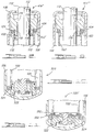
Figure 2 is a longitudinal cross-sectional view of a shock absorber incorporating a floating pressure tube; -
Figure 3 is a side view of a unique aluminum piston rod with a steel cap; -
Figure 4 is an enlarged side view of a threaded steel cap; -
Figure 5 is an enlarged side view of a bonded steel cap; -
Figure 6 is an enlarged cross-sectional view of a compensating rod guide assembly with Belleville springs; -
Figure 7 is an enlarged cross-sectional view of a compensating rod guide assembly with a bearing bush retainer; -
Figure 8 is an enlarged cross-sectional view of an alternate compensating rod guide assembly with a bearing bush retainer; -
Figure 9 is an enlarged cross-sectional view of a compensating rod guide assembly with a retainer; -
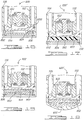
Figure 10 is an enlarged cross-sectional view of a compensating cylinder end assembly with Belleville springs; -
Figure 11 is an enlarged cross-sectional view of the compensating cylinder end assembly ofFigure 10 illustrating a circle-clip and retainer support for the compensating member; -
Figure 12 is an enlarged cross-sectional view of the compensating cylinder end assembly ofFigure 10 illustrating a spring retainer for the compensating member; -
Figure 13 is an enlarged cross-sectional view of the compensating cylinder end assembly ofFigure 10 illustrating a double ring retainer for a compensating member; -
Figure 14 is an enlarged cross-sectional view of an alternate compensating cylinder end assembly having a two piece end assembly that sandwiches the compensating member; -
Figure 15 is an enlarged cross-sectional view of an alternate compensating cylinder end assembly illustrating the pressure tube and compensating member disposed within the valve assembly; -
Figure 16 is an enlarged cross-sectional view of a compensating cylinder end assembly with Belleville springs at the base; -
Figure 17 is an enlarged cross-sectional view of a compensating cylinder end assembly with an elastomeric block at the base; -
Figure 18 is an enlarged cross-sectional view of a compensating cylinder end assembly with gas pressure at the base; and -
Figure 19 is an enlarged cross-sectional view of an alternate compensating cylinder end assembly with gas pressure at the base. - Continued reference is made generally to
Figure 1 and specifically to the components of shock absorber 100 throughout the subsequent description. It is to be understood that the construction ofshock absorber 100 is merely exemplary in nature and is only intended to illustrate one type of hydraulic damping apparatus within which the compensating elements of the present invention can be utilized. - Referring now to the drawings in which like reference numerals designate like or corresponding parts throughout the several views, there is shown in
Figure 2 a unique compensatingshock absorber 200 having a floatingpressure tube 202 and abase valve assembly 222.Rod guide assembly 114 andbase valve assembly 222 are mechanically secured toreserve tube 106. As the relative length ofreserve tube 106 changes due to thermal conditions, the relative distance betweenrod guide assembly 114 andbase valve assembly 222 changes. In the prior art,pressure tube 102 is fixed at one end to one portion ofrod guide assembly 114 and at the other end tobase valve assembly 122, such that changes in the length ofpressure tube 102 due to thermal conditions were compensated for using amulti-piece valve assembly 122. In this embodiment of the present invention, a floatingpressure tube 202 replacespressure tube 102 of the prior art in order to compensate for the different thermal expansions ofreserve tube 106 and floatingpressure tube 202. Floatingpressure tube 202 is sealed torod guide assembly 114 andbase valve assembly 222 using O-rings 204. Floatingpressure tube 202 is able to move freely betweenrod guide assembly 114 andbase valve assembly 222 as the relative length ofreserve tube 106 changes. Thus, both a standard valve guide assembly and a standard base valve assembly can be easily modified to accept floatingpressure tube 202. - In another embodiment of prior
art shock absorber 100, ahybrid piston rod 312 replaces the priorart piston rod 112 as shown inFigures 3-5 . Typically the priorart piston rod 112 is made from steel whilerod guide assembly 114 is made from aluminum. Under extreme thermal conditions the seal betweenpiston rod 112 androd guide 114 can be broken by the different thermal expansion of the two materials.Hybrid piston rod 312 includes analuminum piston shaft 314 and asteel piston post 316. As shown inFigure 4 ,piston post 316 includes aninternal bore 318 which slidingly receives the end ofpiston shaft 314. A circle-clip 320 retains the assembly ofpiston post 316 andpiston shaft 316. As shown in an alternative embodiment inFigure 4 ,piston post 316 has an open threadedbore 322 for receiving a threaded end ofpiston shaft 314.Piston post 316 may be threaded on topiston shaft 314. Alternatively, as seen inFigure 5 , a modifiedsteel piston post 330 with aflat end 332 may be adhesively secured to the end ofpiston shaft 314. In operation,aluminum piston shaft 314 expands and contracts at the same rate as aluminumrod guide assembly 114 and thus prevents a break in the seal between the two.Steel piston post 316, or alternately modifiedsteel piston post 320, absorbs the axial force onpiston rod 312 whenshock absorber 100 is in compression. - In still another embodiment of prior
art shock absorber 100, various compensating piston rod guide assemblies are shown inFigures 6-9 . The compensating pistonrod guide assembly 414, as shown inFigure 6 , supports and guides the movement ofpiston rod 112 and also compensates for the different thermal expansion ofpressure tube 102 andreserve tube 106. Compensating pistonrod guide assembly 414 includes bore 116 andbushing 118, as well as a plurality, an even number in the preferred embodiment, of Belleville springs 424 disposed betweenrod guide 414 andpressure tube 102. The difference in thermal expansion betweensteel pressure tube 102 andaluminum reserve tube 106 is compensated for by the increase or decrease in the compensation of Belleville springs 424. - On the left side of
Figure 7 , an alternate compensating piston rod guide 414' is shown. Alternate piston rod guide 414' includes a bearingbush retainer 450 disposed between Belleville springs 424 and rod guide 414'. Bearingbush retainer 450 seals rod guide 414' andpressure tube 102 and retainsbushing 118, and is further designed to support Belleville springs 424. The thermal expansion ofpressure tube 102 is directly compensated for by Belleville springs 424. On the right side ofFigure 7 , piston rod guide 414' is shown with bearingbush retainer 450 being replaced by compensation retainer 450'. Compensation retainer 450' functions the same as bearingbush retainer 450 in that it retains bushing 118 and it is designed to support Belleville springs 424. The thermal expansion is directly compensated for by Belleville springs 424. - In another embodiment, a compensating
piston rod guide 414" is shown on the left side ofFigure 8 , wherein bearingbush retainer 452 is disposed between thepressure tube 102 and Belleville springs 424. Bearingbush retainer 452 is similar to bearingbush retainer 450 in that it sealsrod guide 414" andpressure tube 102 and it supports Belleville springs 424. The difference between bearingbush retainer rod guide 414" and bearingbush 452 instead of between bearingbush retainer 450 andpressure tube 102 as shown inFigure 7 . The thermal expansion is directly compensated for by Belleville springs 424. On the right side ofFigure 8 ,piston rod guide 414" is shown with bearingbush retainer 452 being replaced by compensation retainer 452'. Compensation retainer 450' functions the same as bearing bush retainer 452' in that it retains bushing 118 and it is designed to support Belleville springs 424 with Belleville springs 424 being disposed betweenrod guide 414" and bush retainer 452'. The thermal expansion is directly compensated for by Belleville springs 424. - In still another embodiment, a compensating
piston rod guide 414"' is shown inFigure 9 , wherein bearingbush retainer 452 has been replaced by acompensation spring support 460.Spring support 460 acts to support Belleville springs 424 but it does not retainbushing 118. Belleville springs 424 are disposed between rod guide 414'" andspring support 460. The thermal expansion is directly compensated for by Belleville springs 424. - In yet further embodiments of prior
art shock absorber 100, various compensating cylinder end assemblies are shown inFigures 10-19 . InFigure 10 , a compensating cylinder end assembly, generally designated as 520, is located at the lower end ofpressure tube 102 and functions to control the flow of hydraulic fluid betweencompression chamber 104 andfluid reservoir 108. Compensatingend assembly 520 further acts to compensate for the differing axial thermal expansion between the various components ofshock absorber 100. - In
Figure 10 , compensatingcylinder end assembly 520 includes abase valve assembly 522 and a plurality, an even number in the preferred embodiment, of Belleville springs 524 disposed betweenpressure tube 102 andbase valve assembly 522. The difference in thermal expansion between thesteel pressure tube 102 and thealuminum reserve tube 106 is compensated for by the increase or decrease in the compression of Belleville springs 524. This embodiment differs from the prior art shown inFigure 1 by eliminating the need for the multi-piecebase valve assembly 122 shown inFigure 1 . - Various methods for securing Belleville springs 524 to an end assembly are shown in
Figures 11-14 . InFigure 11 , the compensating cylinder end assembly 520' includes areaction ring 550.Reaction ring 550 is retained to the outside ofpressure tube 102 by a circle-clip 552. Belleville springs 524 are disposed betweenring 550 andcompression valve assembly 522. - In
Figure 12 , a compensatingcylinder end assembly 520" includes an S-shapedspring retainer 560.Spring retainer 560 is positioned between the bottom ofpressure tube 102 and the top of Belleville springs 524, and acts to retain Belleville springs 524 betweenspring retainer 560 andvalve assembly 522. - In
Figure 13 , the compensatingcylinder end assembly 520"' includes afirst retaining ring 570 and asecond retaining ring 572. First retainingring 570 is positioned such that it is in contact with the bottom ofpressure tube 102.Second retaining ring 572 is secured tovalve assembly 522. Belleville springs 524 are disposed between first retainingring 570 andsecond retaining ring 572. - In
Figure 14 , an alternate compensating cylinder end base valve assembly is designated at 620. Compensating endbase valve assembly 620 is divided into two portions, anupper portion 650 and alower portion 652, and includes a plurality of Belleville springs 624 disposed between the twoportions Upper portion 650 is connected to pressuretube 102 andlower portion 652 is connected to or abutsreserve tube 106.Upper portion 650 fits withinlower portion 652 and is sealed by an O-ring 654. Belleville springs 624 are disposed between the twoportions pressure tube 102 andreserve tube 106 by movingupper portion 650 andlower portion 652 towards or away from each other. - In
Figure 15 , an alternate compensating cylinder end assembly is designated at 720.Cylinder end assembly 720 includes abase valve assembly 722 having acylindrical wall 750 and a plurality of Belleville springs 724.Cylindrical wall 750 is connected to and surrounds abase valve assembly 722 and further extends towards the opposite end ofshock absorber 100.Pressure tube 102 slides withincylindrical wall 750, and is sealed by an O-ring 752. Belleville springs 724 are disposed betweenpressure tube 102 andvalve assembly 722 withincylindrical wall 750. - In another embodiment of
shock absorber 100, compensatingcylinder end assembly 820 is shown inFigure 16 . Compensatingend assembly 820 includes abase valve assembly 822, a plurality of Belleville springs 824, abase plate 850, an O-ring 852, and abottom retainer 854.Base plate 850 is capable of moving axially and is sealed toreserve tube 106 by O-ring 852.Bottom retainer 854 is fixed toreserve tube 106 using aretaining ring 856 and provides a flat, stable bottom forcylinder end assembly 820. Belleville springs 824, an even number in the preferred embodiment, are disposed betweenbase plate 850 andbottom retainer 854. Belleville springs 824 act to compensate for the different thermal expansion of the various components ofshock absorber 100 throughbase plate 850 andbottom retainer 854. In an alternate cylinder end assembly 820', as shown inFigure 17 , Belleville springs 824 are replaced with anelastomeric block 860.Elastomeric block 860 is disposed betweenbase plate 850 andbottom retainer 854 and compensates for the different thermal expansion ofpressure tube 102 andreserve tube 106 by expanding or compressing as necessary. - In compressing
cylinder end assembly 920, which includes abase valve assembly 922 as shown inFigure 18 ,pressurized gas 950, for example compressed air, is disposed between abase plate 952 and abottom retainer 954.Bottom retainer 954 is sealed toreserve tube 106 by aweld 956 or other means known in the art such that thegas 950 remains pressurized.Pressurized gas 950 compensates for the different thermal expansion ofpressure tube 102 andreserve tube 106 by expanding or compressing as necessary, and also reduces the weight of the shock absorber. In alternate cylinder end assembly 920' as shown inFigure 19 ,bottom retainer 954 has been removed.Pressurized gas 950 is disposed betweenbase plate 952 andreserve tube 106 and compensates directly for the different thermal expansion of thepressure tube 102 and thereserve tube 106. - While the above detailed description describes the preferred embodiment of the present invention, it should be understood that the present invention is susceptible to modification, variation and alteration without deviating from the scope of the subjoined claims.
Claims (23)
- A shock absorber (200) which compensates for thermal expansion, and which includes a compression chamber (104), a rod guide assembly (114), a piston (110) slidably disposed within said compression chamber, and a piston rod (112) connected to said piston, a reserve tube (106), and a cylinder end assembly (120),
characterized in that
said shock absorber further comprises a floating pressure tube (202) which forms said compression chamber, said floating pressure tube slidingly engaging said rod guide assembly;
said reserve tube is disposed around said floating pressure tube (202), said reserve tube and said floating pressure tube defining a fluid reservoir (108);
said cylinder end assembly (120) is disposed between said compression chamber and said fluid reservoir for controlling the flow of fluid between said compression chamber and said fluid reservoir, said floating pressure tube slidingly engaging said cylinder end assembly; and
a first biasing member (424) is disposed between said floating pressure tube and said rod guide assembly for urging said floating pressure tube axially away from said rod guide assembly;
said pressure tube being able to move freely relative to said rod guide assembly and said cylinder end assembly. - The shock absorber according to Claim 1, wherein said piston rod comprises:a two-piece piston rod (312) connected to said piston, said two-piece piston rod including a shaft (314) and a piston post (316), said piston post being secured to said piston (110).
- The shock absorber according to Claim 2, wherein said shaft is made from a first material and said piston post is made from a second material.
- The shock absorber according to Claim 3, wherein said piston post (316) is threaded such that it screws onto said shaft (314).
- The shock absorber according to Claim 3, wherein said piston post (316) is bonded to said shaft (314).
- The shock absorber according to Claim 3, wherein said piston post (316) is secured to said shaft by a circle-clip (320).
- The shock absorber according to Claim 1, wherein said first biasing member is at least one Belleville spring (414).
- The shock absorber according to Claim 1, wherein a retainer (450) is disposed between said rod guide assembly and said first biasing member.
- The shock absorber according to Claim 1, wherein a retainer (452) for supporting said first biasing member is disposed between said first biasing member and said floating pressure tube.
- The shock absorber according to Claim 1, wherein said rod guide assembly further includes a bushing (118) for facilitating movement of said piston rod.
- The shock absorber according to Claim 10, wherein a retainer (450) retains said bushing.
- The shock absorber according to Claim 1 further comprising:a second biasing member (524) disposed between said floating pressure tube (202) and said cylinder end assembly for urging said floating pressure tube away from said cylinder end assembly (120).
- The shock absorber according to Claim 12, wherein said second biasing member is a Belleville spring.
- The shock absorber according to Claim 13, wherein said Belleville spring is secured to said cylinder end assembly by a circle-clip (552).
- The shock absorber according to Claim 13, wherein said spring is secured to said cylinder end assembly by a spring retainer (560).
- The shock absorber according to Claim 13, wherein said spring is disposed between two radial retainers (570, 572) secured to the cylinder end assembly.
- The shock absorber according to Claim 12, wherein said cylinder end assembly has two portions, a top portion (650) connected to said floating pressure tube and a bottom portion (652) connected to said reserve tube, said top portion slidingly engaging said bottom portion.
- The shock absorber according to Claim 17, wherein said second biasing member (524) is disposed between said top portion (650) and said bottom portion (652).
- The shock absorber according to Claim 12, wherein said second biasing member and one end of said floating pressure tube are disposed within said cylinder end assembly.
- The shock absorber according to Claim 1 further comprising:a base plate (850) slidingly engaging said reserve tube (106) adjacent said cylinder end assembly; anda second biasing member (824) disposed between said base plate and an end of said reserve tube for urging said base plate away from said end of said reserve tube.
- The shock absorber according to Claim 20, wherein said second biasing member is a Belleville spring (824).
- The shock absorber according to Claim 20, wherein said second biasing member is an elastomeric block (860).
- The shock absorber according to Claim 20, wherein said second biasing member is a pressurized gas (950).
Applications Claiming Priority (2)
| Application Number | Priority Date | Filing Date | Title |
|---|---|---|---|
| US10/671,354 US7004293B2 (en) | 2003-09-25 | 2003-09-25 | Thermal expansion compensation shock absorber |
| PCT/US2004/030783 WO2005030506A2 (en) | 2003-09-25 | 2004-09-21 | Improved thermal expansion compensation shock absorber |
Publications (3)
| Publication Number | Publication Date |
|---|---|
| EP1664584A2 EP1664584A2 (en) | 2006-06-07 |
| EP1664584A4 EP1664584A4 (en) | 2009-09-30 |
| EP1664584B1 true EP1664584B1 (en) | 2018-01-03 |
Family
ID=34376121
Family Applications (1)
| Application Number | Title | Priority Date | Filing Date |
|---|---|---|---|
| EP04784599.5A Expired - Lifetime EP1664584B1 (en) | 2003-09-25 | 2004-09-21 | Improved thermal expansion compensation shock absorber |
Country Status (5)
| Country | Link |
|---|---|
| US (2) | US7004293B2 (en) |
| EP (1) | EP1664584B1 (en) |
| CN (1) | CN100476234C (en) |
| BR (1) | BRPI0414797A (en) |
| WO (1) | WO2005030506A2 (en) |
Families Citing this family (22)
| Publication number | Priority date | Publication date | Assignee | Title |
|---|---|---|---|---|
| US20060011433A1 (en) * | 2004-07-19 | 2006-01-19 | Carlstedt Robert P | Damper valve body loading |
| JP2006064098A (en) * | 2004-08-27 | 2006-03-09 | Kayaba Ind Co Ltd | Front fork |
| CA2575089A1 (en) * | 2007-01-17 | 2008-07-17 | Mark Davis | Shock absorber |
| US8561768B2 (en) * | 2007-08-31 | 2013-10-22 | Honda Motor Co., Ltd. | Vehicle damper and method |
| US20100011681A1 (en) * | 2008-07-21 | 2010-01-21 | Wei-Hua Chiang | Shock Absorber |
| CN101793273B (en) * | 2009-01-30 | 2017-05-17 | 日立汽车系统株式会社 | Cylinder apparatus |
| JP5192438B2 (en) * | 2009-04-28 | 2013-05-08 | カヤバ工業株式会社 | Double cylinder type hydraulic shock absorber |
| EP2295693A1 (en) * | 2009-08-27 | 2011-03-16 | Joseph Talpe | Door closing mechanism |
| US8128418B1 (en) | 2010-08-17 | 2012-03-06 | Hamilton Sundstrand Space Systems International, Inc. | Thermal expansion compensator having an elastic conductive element bonded to two facing surfaces |
| AU2011323791B2 (en) | 2010-10-25 | 2015-11-05 | Msi Defense Solutions, Llc | A hydraulic suspension system for lowering the ride height of a vehicle |
| DE102014202201A1 (en) * | 2014-02-06 | 2015-08-06 | Zf Friedrichshafen Ag | Two pipe vibration |
| CN107206861B (en) * | 2014-11-26 | 2019-09-06 | 天纳克汽车营运公司 | Shock Absorber Having Composite Base Assembly With Overmolded Closure Insert |
| US10006516B2 (en) * | 2014-11-26 | 2018-06-26 | Tenneco Automotive Operating Company Inc. | Shock absorbers having a composite base assembly with axial flexibility compensation |
| CN104565174B (en) * | 2014-12-23 | 2017-03-01 | 奇瑞商用车(安徽)有限公司 | A kind of vibroshock with aerofluxuss collocation structure |
| DE102015212404A1 (en) * | 2015-07-02 | 2017-01-05 | Volkswagen Aktiengesellschaft | Hydraulic vibration damper |
| CN108885315B (en) * | 2016-04-01 | 2021-07-09 | Ipg光子公司 | Fiber Optic Cable Connector |
| DE102018220628B4 (en) * | 2018-11-29 | 2022-08-18 | Thyssenkrupp Ag | Vibration damper and vehicle |
| US11914199B2 (en) | 2019-10-29 | 2024-02-27 | Ipg Photonics Corporation | Optical fiber cable connector |
| DE102019131319A1 (en) * | 2019-11-20 | 2021-05-20 | Thyssenkrupp Ag | Vibration damper and motor vehicle with such a vibration damper |
| US11378150B1 (en) * | 2021-01-12 | 2022-07-05 | Safran Landing Systems Canada Inc. | Temperature compensated shock absorber |
| US11794542B2 (en) | 2021-03-08 | 2023-10-24 | DRiV Automotive Inc. | Shock absorber with metal damper tube and composite mounting attachment and spring seat |
| CN113775688B (en) * | 2021-08-27 | 2022-08-16 | 中国第一汽车股份有限公司 | Continuous damping control shock absorber |
Family Cites Families (17)
| Publication number | Priority date | Publication date | Assignee | Title |
|---|---|---|---|---|
| DE2257557A1 (en) * | 1972-11-24 | 1974-06-06 | Fichtel & Sachs Ag | VENTILATION DEVICE FOR TWO-TUBE VIBRATION DAMPER USED BY A RIGID WASHER |
| US4934491A (en) * | 1987-12-14 | 1990-06-19 | Atsugi Motor Parts Company, Limited | Shock absorber with improved structure of thrusting piston assembly |
| DE3831719B4 (en) * | 1988-09-17 | 2011-06-01 | Zf Sachs Ag | Seal for a piston rod guided axially movably in a container |
| CN2076937U (en) * | 1990-05-18 | 1991-05-15 | 罗良祖 | Automobile dashpot radial high-loading support and oil seal device |
| DE4230238A1 (en) * | 1992-09-10 | 1994-03-17 | Fichtel & Sachs Ag | Coaxial suspension damper - is temperature compensated by expansion element between piston rod seal and end of pressure cylinder |
| GB2287770B (en) * | 1994-03-21 | 1997-11-26 | Monroe Auto Equipment Co | Piston post for a damper |
| CN2198451Y (en) * | 1994-07-08 | 1995-05-24 | 清华大学 | Seal structure of automobile damper sleeve |
| DE19512866C2 (en) * | 1995-04-06 | 1997-11-20 | Fichtel & Sachs Ag | Vibration damper |
| DE19515643C1 (en) * | 1995-04-28 | 1996-11-07 | Fichtel & Sachs Ag | Suspension strut with aluminum container |
| US5893436A (en) * | 1996-01-16 | 1999-04-13 | Tenneco Automotive Inc. | One piece aluminum pressure tube with rod guide for shock absorbers |
| US5727662A (en) * | 1996-02-05 | 1998-03-17 | Monroe Auto Equipment Company | Thermal expansion compensation device for shock absorbers |
| DE19628152C2 (en) * | 1996-07-12 | 2001-07-19 | Krupp Bilstein Gmbh | Hydraulic vibration damper |
| DE19823878C1 (en) * | 1998-05-28 | 1999-12-23 | Mannesmann Sachs Ag | Two-tube vibration damper with a compensating element |
| FR2799808B1 (en) * | 1999-10-14 | 2002-03-08 | Peugeot Citroen Automobiles Sa | SUSPENSION SHOCK ABSORBER |
| JP4371342B2 (en) * | 2000-09-01 | 2009-11-25 | 株式会社ショーワ | Tube structure of hydraulic shock absorber and tube manufacturing method |
| JP2003049887A (en) * | 2001-08-02 | 2003-02-21 | Showa Corp | Shaft seal structure of hydraulic shock absorber and method of assembling the same |
| DE10138322B4 (en) * | 2001-08-10 | 2004-01-29 | Deutsches Zentrum für Luft- und Raumfahrt e.V. | Piston rod assembly |
-
2003
- 2003-09-25 US US10/671,354 patent/US7004293B2/en not_active Expired - Lifetime
-
2004
- 2004-09-21 BR BRPI0414797-9A patent/BRPI0414797A/en not_active IP Right Cessation
- 2004-09-21 WO PCT/US2004/030783 patent/WO2005030506A2/en not_active Ceased
- 2004-09-21 EP EP04784599.5A patent/EP1664584B1/en not_active Expired - Lifetime
- 2004-09-21 CN CNB2004800280257A patent/CN100476234C/en not_active Expired - Lifetime
-
2005
- 2005-12-05 US US11/294,693 patent/US20060081428A1/en not_active Abandoned
Non-Patent Citations (1)
| Title |
|---|
| None * |
Also Published As
| Publication number | Publication date |
|---|---|
| EP1664584A2 (en) | 2006-06-07 |
| WO2005030506A3 (en) | 2005-09-29 |
| US7004293B2 (en) | 2006-02-28 |
| US20060081428A1 (en) | 2006-04-20 |
| CN100476234C (en) | 2009-04-08 |
| WO2005030506A2 (en) | 2005-04-07 |
| EP1664584A4 (en) | 2009-09-30 |
| US20050067237A1 (en) | 2005-03-31 |
| CN1860312A (en) | 2006-11-08 |
| BRPI0414797A (en) | 2006-11-21 |
Similar Documents
| Publication | Publication Date | Title |
|---|---|---|
| EP1664584B1 (en) | Improved thermal expansion compensation shock absorber | |
| JP4890272B2 (en) | Rod guide and seal system for pneumatic shock absorber | |
| EP0974014B1 (en) | Double-acting shock absorber with volume compensation for the stroke of the rod | |
| CN100526673C (en) | Compensated rod for a frequency dependent damper shock absorber | |
| JPH10205563A (en) | Improved and differential two-way shock absorber not affected by position and having no cavitation action | |
| JPH10318322A (en) | Shock absorber | |
| WO2016112309A1 (en) | Double tube damper with structural pressure tube | |
| JP2009507191A (en) | Rod guide seal | |
| US5727662A (en) | Thermal expansion compensation device for shock absorbers | |
| CA1248980A (en) | Arrangement for a spring suspension system | |
| US6648310B2 (en) | Shock absorber | |
| CN103119321B (en) | Damping unit and method of controlling flow through damping unit piston | |
| US20060042895A1 (en) | Base cup connection for shock absorber | |
| US5893436A (en) | One piece aluminum pressure tube with rod guide for shock absorbers | |
| US7182190B2 (en) | Vibration damper with fire safety device | |
| CN101243266A (en) | Asymmetric inlet damper valve | |
| JP2010014196A (en) | Single cylinder-type hydraulic shock absorber | |
| JP5426853B2 (en) | Hydraulic buffer | |
| JPS6228331B2 (en) | ||
| JP5106346B2 (en) | Shock absorber | |
| JP4761466B2 (en) | Pneumatic shock absorber | |
| JP4535949B2 (en) | Pneumatic shock absorber | |
| JP3068266U (en) | Shock absorber | |
| CN119022019A (en) | Top mounted bump control dampers | |
| JP3034413B2 (en) | Hydraulic shock absorber |
Legal Events
| Date | Code | Title | Description |
|---|---|---|---|
| PUAI | Public reference made under article 153(3) epc to a published international application that has entered the european phase |
Free format text: ORIGINAL CODE: 0009012 |
|
| 17P | Request for examination filed |
Effective date: 20060320 |
|
| AK | Designated contracting states |
Kind code of ref document: A2 Designated state(s): DE FR GB |
|
| DAX | Request for extension of the european patent (deleted) | ||
| RBV | Designated contracting states (corrected) |
Designated state(s): DE FR GB |
|
| A4 | Supplementary search report drawn up and despatched |
Effective date: 20090831 |
|
| 17Q | First examination report despatched |
Effective date: 20111212 |
|
| GRAP | Despatch of communication of intention to grant a patent |
Free format text: ORIGINAL CODE: EPIDOSNIGR1 |
|
| INTG | Intention to grant announced |
Effective date: 20170811 |
|
| GRAS | Grant fee paid |
Free format text: ORIGINAL CODE: EPIDOSNIGR3 |
|
| GRAA | (expected) grant |
Free format text: ORIGINAL CODE: 0009210 |
|
| AK | Designated contracting states |
Kind code of ref document: B1 Designated state(s): DE FR GB |
|
| REG | Reference to a national code |
Ref country code: GB Ref legal event code: FG4D |
|
| REG | Reference to a national code |
Ref country code: DE Ref legal event code: R096 Ref document number: 602004052253 Country of ref document: DE |
|
| REG | Reference to a national code |
Ref country code: DE Ref legal event code: R097 Ref document number: 602004052253 Country of ref document: DE |
|
| PLBE | No opposition filed within time limit |
Free format text: ORIGINAL CODE: 0009261 |
|
| STAA | Information on the status of an ep patent application or granted ep patent |
Free format text: STATUS: NO OPPOSITION FILED WITHIN TIME LIMIT |
|
| 26N | No opposition filed |
Effective date: 20181005 |
|
| GBPC | Gb: european patent ceased through non-payment of renewal fee |
Effective date: 20180921 |
|
| PG25 | Lapsed in a contracting state [announced via postgrant information from national office to epo] |
Ref country code: FR Free format text: LAPSE BECAUSE OF NON-PAYMENT OF DUE FEES Effective date: 20180930 |
|
| PG25 | Lapsed in a contracting state [announced via postgrant information from national office to epo] |
Ref country code: GB Free format text: LAPSE BECAUSE OF NON-PAYMENT OF DUE FEES Effective date: 20180921 |
|
| P01 | Opt-out of the competence of the unified patent court (upc) registered |
Effective date: 20230528 |
|
| PGFP | Annual fee paid to national office [announced via postgrant information from national office to epo] |
Ref country code: DE Payment date: 20230822 Year of fee payment: 20 |
|
| REG | Reference to a national code |
Ref country code: DE Ref legal event code: R071 Ref document number: 602004052253 Country of ref document: DE |