EP1655754A2 - Mehrfunktionschalter für Kraftfahrzeug - Google Patents
Mehrfunktionschalter für Kraftfahrzeug Download PDFInfo
- Publication number
- EP1655754A2 EP1655754A2 EP06002589A EP06002589A EP1655754A2 EP 1655754 A2 EP1655754 A2 EP 1655754A2 EP 06002589 A EP06002589 A EP 06002589A EP 06002589 A EP06002589 A EP 06002589A EP 1655754 A2 EP1655754 A2 EP 1655754A2
- Authority
- EP
- European Patent Office
- Prior art keywords
- knob
- switch
- axle
- switch unit
- sliding element
- Prior art date
- Legal status (The legal status is an assumption and is not a legal conclusion. Google has not performed a legal analysis and makes no representation as to the accuracy of the status listed.)
- Granted
Links
Images


Classifications
-
- B—PERFORMING OPERATIONS; TRANSPORTING
- B60—VEHICLES IN GENERAL
- B60Q—ARRANGEMENT OF SIGNALLING OR LIGHTING DEVICES, THE MOUNTING OR SUPPORTING THEREOF OR CIRCUITS THEREFOR, FOR VEHICLES IN GENERAL
- B60Q1/00—Arrangement of optical signalling or lighting devices, the mounting or supporting thereof or circuits therefor
- B60Q1/02—Arrangement of optical signalling or lighting devices, the mounting or supporting thereof or circuits therefor the devices being primarily intended to illuminate the way ahead or to illuminate other areas of way or environments
- B60Q1/04—Arrangement of optical signalling or lighting devices, the mounting or supporting thereof or circuits therefor the devices being primarily intended to illuminate the way ahead or to illuminate other areas of way or environments the devices being headlights
- B60Q1/14—Arrangement of optical signalling or lighting devices, the mounting or supporting thereof or circuits therefor the devices being primarily intended to illuminate the way ahead or to illuminate other areas of way or environments the devices being headlights having dimming means
- B60Q1/1446—Arrangement of optical signalling or lighting devices, the mounting or supporting thereof or circuits therefor the devices being primarily intended to illuminate the way ahead or to illuminate other areas of way or environments the devices being headlights having dimming means controlled by mechanically actuated switches
- B60Q1/1453—Hand actuated switches
- B60Q1/1461—Multifunction switches for dimming headlights and controlling additional devices, e.g. for controlling direction indicating lights
- B60Q1/1469—Multifunction switches for dimming headlights and controlling additional devices, e.g. for controlling direction indicating lights controlled by or attached to a single lever, e.g. steering column stalk switches
- B60Q1/1476—Multifunction switches for dimming headlights and controlling additional devices, e.g. for controlling direction indicating lights controlled by or attached to a single lever, e.g. steering column stalk switches comprising switch controlling means located near the free end of the lever, e.g. press buttons, rotatable rings
Definitions
- the present invention relates to an automotive combination switch incorporating switching mechanisms such as light control switch unit, wiper control switch unit, etc. to be installed on an automotive steering column.
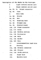
- FIG. 14 shows structure of a conventional automotive combination switch as viewed from the bottom
- Fig. 15 is a side view of the automotive combination switch.
- a light control switch unit 1 houses in it a lighting switch, a dimmer/passing switch, a turn signal switch and various other switches of the category.
- a wiper control switch unit 2 houses in it various function switches such as front windshield wiper switch, rear windshield wiper switch, front windshield washer switch, and other switches related to wiper. Electric signals from the respective light control switch unit 1 and the wiper control switch unit 2 are delivered outside through each of output connectors 3a, 3b attached to the switch units 1, 2, to be supplied severally to a circuit outside the combination switch (a circuit in an automobile).
- Numeral 5 represents a main body.
- each of the switch units is assembled in an independent block configuration for easy mounting/detaching from main body, reliable means for interconnection among the switch units is needed, which accomplishes a reliable coupling during mounting operation absorbing dimensional dispersion of constituent parts or that caused by practical handling in the mounting operation.
- the present invention aims to offer an automotive combination switch, with which the mounting operation may be accomplished easily and reliably.
- the combination switch comprises an relay connector, and made of a reduced number of components in a simplified structure.
- An invented automotive combination switch comprises a light control switch unit containing a plurality of function switches such as a turn signal switch, a dimmer switch and a lighting switch housed in a case having a rib to be fitting to a groove of main body, an elastic mounting knob, and a stopper peg mounted thereon, which case being provided at the lower part with a fixed connector for delivering signals from the switches outside; a wiper control switch unit containing a plurality of function switches such as a wiper switch, a washer switch housed in a case likewise having a rib, an elastic mounting knob, a stopper peg provided thereon and a fixed connector; and an interconnection lead wire attached to the main body with a mobility, which lead wire having at both ends a movable connector which is to be engaged with respective fixed connectors of the switch units when mounted to the main body.
- a light control switch unit containing a plurality of function switches such as a turn signal switch, a dimmer switch and a lighting switch housed in a case
- the movable connector of relay connector which has been attached to the main body with a certain mobility can adapt its location to the fixed connector of switch unit for coupling. Therefore, such troubles as twisted coupling or uninsertability among the connectors may be avoided. Furthermore, as the relay connector has been made with commercial lead wires readily available, it may be presented at low cost with a high reliability, without requiring any special moulds or components.
- Fig. 7 is a cross sectional side view of an invented automotive combination switch, showing a practical structure of the switch unit in detail
- Fig. 8 is a vertical cross sectional view showing the structure of the switch unit
- Fig. 9 is a cross sectional side view of the switch unit showing the vertical action of the switch unit
- Fig. 10 is a plane view showing the structure of the switch unit
- Fig. 11 is a plane view showing the horizontal action of the switch unit
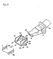
- Fig. 12 is an exploded perspective view of the switch unit used to describe an operating element and insertion thereto of a driving axle of knob
- Fig. 13 is a perspective view showing the reverse surface of the operating element.
- Fig. 14 shows the structure of a prior art automotive combination switch, as viewed from the bottom
- Fig. 15 is a side view of the combination switch.
- FIG. 1 shows the structure of an invented automotive combination switch, as viewed from the bottom
- Fig. 2 is a side view of the combination switch
- Fig. 3 is a cross sectional plane view showing details of a movable connector
- Fig. 4 is a cross sectional side view of the movable connector
- Fig. 5 is a front view showing a holder portion of the movable connector
- Fig. 6(a), (b) are drawings used to describe the coupling action among the movable connector and the fixed connector.
- a lib 6a, 6b which fits to a groove 5a, 5b of a main body 5 for positional orientation, a mounting knob 7a, 7b made of an elastic resin which is shaped in a form U so as to provide an elastic force by making use of elasticity of the resin, and a stopper peg 8a, 8b provided thereon in a certain specific place, all of the above items have been made as a single molded structure.
- a fixed connector 10a, 10b soldered to a printed board 9a, 9b is provided facing towards an open portion of the case 4a, 4b, for delivering the signals from function switches in each of the switch units out.
- the printed board 9a, 9b and the fixed connector 10a, 10b are protected by a cover 11a, 11b.
- Fig. 3 and Fig. 4 show the movable connector of Fig. 1 and Fig. 2 further in detail.
- the movable connector 19a, 19b is comprised of a holder 15a, 15b having at both ends a hole 14a, 14b to be engaged movable with a protrusion 13a, 13b of a holding portion 12a, 12b which has been provided to form an integral part of the main body 5, and a housing 18 which is held fixed by an elastic nail 16a, 16b provided in the holder 15a, 15b and houses in it a terminal section of interconnection lead wire 17 caulked thereto.
- the interconnection lead wire 17 having the movable connector 19a, 19b at both ends is disposed with the protrusion 13a, 13b fitted to the hole 14a, 14b, so as it faces to a position corresponding approximately to the fixed connector 10a, 10b of switch unit 1, 2.
- the movable connector 19a, 19b does not fall off the main body 5.
- the main body 5 and the holder 15a, 15b are coupled by means of press-fitting, etc. of the holding portion 12a, 12b taking advantage of the elasticity of the resin.
- a stopper 20a, 20b provided as an integral part of the main body 5, for retaining the movable connector 19a, 19b in a case when a switch unit is withdrawn.
- a digital circuit has been disposed, in the wiper switch unit 2. Therefore, an output connector 3 is provided in the wiper switch unit 2 for delivering signals to a circuit in automobile end.
- Each of the switch units is held mounted to a specified position through insertion of the rib 6a, 6b of case 4a, 4b along the groove 5a, 5b of the main body.
- the stopper peg 8a, 8b is elastically hooked to a latching wall of main body 5 by an elasticity of the mounting knob 7a, 7b, and the switch unit is firmly held by main body without play; when, the movable connector 19a, 19b and the fixed connector 10a, 10b being kept inserted.
- positioning of the fixed connector 10a, 10b of switch unit is dispersed due to such factors as a play in the fixing of case 4a, 4b to main body 5, displaced fixing of fixed connector 10a, 10b to printed board 9a, 9b, displaced fixing of printed board 9a, 9b to case 4a, 4b, a dispersion in the dimensions of constituent components, etc.; as a result, it does not always coincide with the location of the movable connector 19a, 19b attached to the main body.
- the movable connector 19a, 19b of the present embodiment 1 is supported by the protrusion 13a, 13b with respect to the main body 5, and does not fall off the body; however, because it is supported so as it can move for a distance equivalent to the dimensional difference among the hole 14a, 14b and the protrusion 13a, 13b, the coupling of connectors is consummated by adapting the location to be suitable to the position of fixed connector 10a, 10b, absorbing the dispersion in the positioning.
- the movable connector 19a, 19b for interconnection does not move in the withdrawing direction, because the holder 15a, 15b is restricted by the stopper 20a, 20b.
- the fixed connector 10a, 10b of the switch unit is withdrawn, while the movable connector 19a, 19b is retained.
- the above structured movable connector 19a, 19b realizes a reliable structure for an relay connector of an invented automotive combination switch; with which the coupling and decoupling of connection may be accomplished reliably, without making the level of dimensional requirements for the constituent components and units more stringent.
- the connectors may be coupled easier and surer by providing a guide portion 21a, 21b on the encountering ridges of at least one among the fixed connector 10a, 10b of switch unit, and the movable connector 19a, 19b of relay connector, the guide portion 21a, 21b being large enough to cover a displacement value equal to the amount of relative displacement between the connectors caused by dispersion.
- the movable connector 19a, 19b for interconnection may be guided by the guide portion 21a, 21b to be smoothly inserted for a sure coupling.
- the movable connector 19a, 19b has been fabricated into a single piece component out of a holder 15a, 15b and a housing 18 for holding terminals, each of which has been provided as a separate component, by inserting the housing 18 into the holder 15a, 15b, and preventing the housing 18 from falling-off by a resin nail 16a, 16b provided in the holder 15a, 15b.
- the parts count may be reduced and the assembly operation may also be further simplified if the housing 18 is formed with a resin together with a holder 15a, 15b having a hole 14a, 14b at both ends, completing a movable connector.
- Fig. 7, Fig. 8 show a cross sectional side view and a vertical cross sectional view, respectively, of a switch unit
- Fig. 9, Fig. 11 are a cross sectional side view and a plane view, respectively, used to describe the operation of switch unit
- Fig. 10 is a plane view of the switch unit
- Fig. 12 is an exploded perspective view used to describe an operating element and insertion thereto of a driving axle of knob
- Fig. 13 is a perspective view of the operating element viewed from the bottom.
- numeral 33 denotes a case
- 23a is a fixed knob
- 23b is a movable knob.
- the movable knob 23b is fixed on an axle 28, which axle is penetrating through a hole in the center of the fixed knob 23a and slidably coupled at the driving portion 28a of a ball shape provided at the tip end with a slider 29 of lighting switch housed in the case 33.
- a vertical pivotal axle 31 to be rotatably supported by a hole provided in a sliding element 24 is provided, which pivotal axle 31 is fitted in a pivotal hole 24c of sliding element 24.
- a driving axle 36 is provided to be engaged slidably with a slant slit hole 35a of both side walls 34 of an operating element 35.
- the operating element 35 and the fixed knob 23a are coupled via the driving axle 36.
- a guide axle 35b is provided to be engaged slidably with a guide groove 24b which has been provided in a horizontal direction in the side wall of sliding element 24. This restricts movement of the operating element 35 to the horizontal direction.
- the above sliding element 24 is supported by a horizontal pivotal axle 25 and a lower pivotal axle 24d between the case 33 and an intermediate cover 26 to be freely rotatable in a horizontal plane; also provided at the extreme end is a hollow groove 24a which is to be engaged with a turn signal switch axle 27a of a turn signal switch slider 27.
- a circular arc groove 35c having a U shape cross section is provided to be engaged with a dimmer switch axle 32a of dimmer switch slider 32.
- the dimmer switch slider 32 is supported by a guide rib 26a provided in the intermediate cover 26 and restricted to move in a horizontal direction.
- Each slider of the respective switches is slidably supported between the intermediate cover 26 and the printed board 37, each slider is provided with a contact element 38 (only that of dimmer switch is shown), and the sliding element 38 slides over the surface of printed board 37 to open and close a pattern formed thereon.
- the operating element 35 has been engaged by the guide groove 24b in the side of sliding element 24 and the guide axle 35b so as it can move only in a horizontal direction guided by the guide groove 24b of sliding element 24 (ref. Fig. 8).
- the driving axle 36 moves sliding in the slant slit hole 35a in a rotating motion, and the operating element 35 makes a horizontal shift.
- a circular arc portion 35e, containing the groove having a U shape cross section 35c, provided at a lower part of the operating element 35 shifts likewise.
- a dimmer switch axle 32a of dimmer switch slider 32 having contact element 38 is engaged with the groove having a U shape cross section; as a result, the dimmer switch slider 32 moves along the guide rib 26a of intermediate cover 26 along with the movement of operating element 35, and the contact element 38 opens/closes a pattern on the printed board 37.
- the sliding element 24 sometimes make a rotating shift for the purpose of other switching operation, centered by the horizontal pivotal axle 25 and lower pivotal axle 24d within a horizontal plane.
- the sliding element 24 as well as the operating element 35 engaged with it likewise make the rotating shift
- the dimmer switch axle 32a of dimmer switch slider 32 does not make the shift, and keeps staying in the position because the groove having a U shape cross section 35c disposed in the lower part of operating element 35 has been shaped in a circular arc form as shown in Fig. 13.
- the fixed knob 23a is operated in the state as described above, the same movement as described earlier takes place to perform the present switching instruction, independent of other switching operation.
- the motion of operating element caused by a vertical motion of fixed knob 23a which shifts a sliding element always remains in a horizontal plane, without making any up/down motion. This may flatten the whole structure of a switch.
- insertion of the driving axle 36 of fixed knob 23a into the slant slit hole 35a of operating element 35 may be made easier, if the operating element 35 is formed by resin molding or other such method and a guide hollow 35d is provided at the inserting end for accepting the driving axle 36 of fixed knob 23a, in a manner to make the span slightly narrower than the width of driving axle 36, as shown in Fig. 12.
- the driving axle 36 may be put into engagement with the slant slit hole 35a of operating element 35 easily by taking advantage of elasticity of the resin side wall of operating element 35. This may contribute to increase the productivity in assembly process.
- the turn signal switch may be put into operation by rotating the fixed knob 23a in a horizontal plane, as shown in Fig. 11; the sliding element 24 fitted to the end of fixed knob 23a rotates around the horizontal pivotal axle 25 to put the turn signal switch slider 27, which has been slidably attached to the intermediate cover 26, into action.
- the present invention offers a reliable automotive combination switch having an relay connector between the units, the structure of which being simple containing less component counts, and a high productivity during assembly operation is assured.
- an automotive combination switch may be made more compact and flat.
Applications Claiming Priority (3)
| Application Number | Priority Date | Filing Date | Title |
|---|---|---|---|
| JP12925897A JP3896637B2 (ja) | 1997-05-20 | 1997-05-20 | 自動車用コンビネーションスイッチ |
| JP12926597A JP4110590B2 (ja) | 1997-05-20 | 1997-05-20 | 自動車用コンビネーションスイッチ |
| EP98919650A EP0926691B1 (de) | 1997-05-20 | 1998-05-19 | Mehrfachschalter für kraftfahrzeug |
Related Parent Applications (1)
| Application Number | Title | Priority Date | Filing Date |
|---|---|---|---|
| EP98919650A Division EP0926691B1 (de) | 1997-05-20 | 1998-05-19 | Mehrfachschalter für kraftfahrzeug |
Publications (3)
| Publication Number | Publication Date |
|---|---|
| EP1655754A2 true EP1655754A2 (de) | 2006-05-10 |
| EP1655754A3 EP1655754A3 (de) | 2006-05-31 |
| EP1655754B1 EP1655754B1 (de) | 2008-01-16 |
Family
ID=26464710
Family Applications (2)
| Application Number | Title | Priority Date | Filing Date |
|---|---|---|---|
| EP06002589A Expired - Lifetime EP1655754B1 (de) | 1997-05-20 | 1998-05-19 | Mehrfunktionschalter für Kraftfahrzeug |
| EP98919650A Expired - Lifetime EP0926691B1 (de) | 1997-05-20 | 1998-05-19 | Mehrfachschalter für kraftfahrzeug |
Family Applications After (1)
| Application Number | Title | Priority Date | Filing Date |
|---|---|---|---|
| EP98919650A Expired - Lifetime EP0926691B1 (de) | 1997-05-20 | 1998-05-19 | Mehrfachschalter für kraftfahrzeug |
Country Status (6)
| Country | Link |
|---|---|
| US (1) | US6172314B1 (de) |
| EP (2) | EP1655754B1 (de) |
| AU (1) | AU734495B2 (de) |
| CA (1) | CA2260780A1 (de) |
| DE (2) | DE69835136T2 (de) |
| WO (1) | WO1998053471A1 (de) |
Cited By (2)
| Publication number | Priority date | Publication date | Assignee | Title |
|---|---|---|---|---|
| CN102915896A (zh) * | 2012-09-29 | 2013-02-06 | 慈溪市微型汽车配件厂(普通合伙) | 一种汽车组合开关 |
| CN105070570A (zh) * | 2015-07-16 | 2015-11-18 | 柳州六品科技有限公司 | 一种动力设备用组合开关 |
Families Citing this family (10)
| Publication number | Priority date | Publication date | Assignee | Title |
|---|---|---|---|---|
| JP4629854B2 (ja) * | 2000-11-14 | 2011-02-09 | ナイルス株式会社 | 車両用コンビネーションスイッチ |
| JP3868828B2 (ja) * | 2002-02-28 | 2007-01-17 | 矢崎総業株式会社 | コンビネーションスイッチ |
| JP4301981B2 (ja) * | 2004-03-17 | 2009-07-22 | ナイルス株式会社 | 車両用コンビネーションスイッチ、その組立方法 |
| JP2005332621A (ja) * | 2004-05-18 | 2005-12-02 | Yazaki Corp | コンビネーションスイッチ用レバーの組み付け構造 |
| CN100345713C (zh) * | 2004-09-13 | 2007-10-31 | 余梓杭 | 一种带嵌入式雨刮系统的组合开关 |
| JP5752395B2 (ja) * | 2010-11-09 | 2015-07-22 | 矢崎総業株式会社 | 操作ユニット |
| CN103681158B (zh) * | 2013-12-20 | 2016-03-23 | 昌辉汽车电器(黄山)股份公司 | 一种汽车组合开关 |
| CN103646812A (zh) * | 2013-12-20 | 2014-03-19 | 黄山奥特斯电气有限公司 | 一种汽车变光开关结构 |
| CN111016776B (zh) * | 2019-12-28 | 2023-03-24 | 余姚市瑞玛特电器有限公司 | 组合开关 |
| DE102022132570B3 (de) | 2022-12-07 | 2024-02-08 | Bcs Automotive Interface Solutions Gmbh | Hebelbaugruppe für ein Kraftfahrzeug |
Citations (2)
| Publication number | Priority date | Publication date | Assignee | Title |
|---|---|---|---|---|
| EP0252800A1 (de) * | 1986-06-26 | 1988-01-13 | Jaeger | Schalter, insbesondere für die Steuerung von Wisch-Wasch-Kombinationen von Kraftfahrzeugen |
| FR2662299A1 (fr) * | 1990-05-17 | 1991-11-22 | Jaeger | Commutateur electrique pour vehicule automobile. |
Family Cites Families (9)
| Publication number | Priority date | Publication date | Assignee | Title |
|---|---|---|---|---|
| JPH0316183Y2 (de) * | 1985-07-31 | 1991-04-08 | ||
| DE4016773C2 (de) * | 1990-05-25 | 1999-08-19 | Teves Gmbh Alfred | Elektrischer Schalter, insbesondere zum Betreiben einer Scheibenwisch- und einer Scheibenwaschanlage eines Kraftfahrzeugs |
| JPH06226842A (ja) * | 1993-01-29 | 1994-08-16 | Kinugawa Rubber Ind Co Ltd | 押出成形体の加工装置 |
| US5977494A (en) * | 1995-09-08 | 1999-11-02 | Yazaki Corporation | Symmetrically mounted switches on steering wheel column body including wiring connection and control unit |
| JP3435935B2 (ja) * | 1995-10-26 | 2003-08-11 | 松下電器産業株式会社 | 車両用コンビネーションスイッチ |
| JPH10199375A (ja) * | 1997-01-17 | 1998-07-31 | Yazaki Corp | コンビネーションスイッチ装置 |
| JPH10228844A (ja) * | 1997-02-14 | 1998-08-25 | Niles Parts Co Ltd | 車両用コンビネーションスイッチの構造 |
| JPH10241504A (ja) * | 1997-02-24 | 1998-09-11 | Yazaki Corp | ステアリング用信号伝達装置 |
| JP3691241B2 (ja) * | 1998-02-27 | 2005-09-07 | ナイルス株式会社 | 車両用レバースイッチ |
-
1998
- 1998-05-19 DE DE69835136T patent/DE69835136T2/de not_active Expired - Lifetime
- 1998-05-19 AU AU72392/98A patent/AU734495B2/en not_active Ceased
- 1998-05-19 EP EP06002589A patent/EP1655754B1/de not_active Expired - Lifetime
- 1998-05-19 DE DE69839028T patent/DE69839028T2/de not_active Expired - Lifetime
- 1998-05-19 EP EP98919650A patent/EP0926691B1/de not_active Expired - Lifetime
- 1998-05-19 WO PCT/JP1998/002190 patent/WO1998053471A1/ja active IP Right Grant
- 1998-05-19 US US09/230,157 patent/US6172314B1/en not_active Expired - Lifetime
- 1998-05-19 CA CA002260780A patent/CA2260780A1/en not_active Abandoned
Patent Citations (2)
| Publication number | Priority date | Publication date | Assignee | Title |
|---|---|---|---|---|
| EP0252800A1 (de) * | 1986-06-26 | 1988-01-13 | Jaeger | Schalter, insbesondere für die Steuerung von Wisch-Wasch-Kombinationen von Kraftfahrzeugen |
| FR2662299A1 (fr) * | 1990-05-17 | 1991-11-22 | Jaeger | Commutateur electrique pour vehicule automobile. |
Cited By (3)
| Publication number | Priority date | Publication date | Assignee | Title |
|---|---|---|---|---|
| CN102915896A (zh) * | 2012-09-29 | 2013-02-06 | 慈溪市微型汽车配件厂(普通合伙) | 一种汽车组合开关 |
| CN102915896B (zh) * | 2012-09-29 | 2014-10-22 | 慈溪市微型汽车配件厂(普通合伙) | 一种汽车组合开关 |
| CN105070570A (zh) * | 2015-07-16 | 2015-11-18 | 柳州六品科技有限公司 | 一种动力设备用组合开关 |
Also Published As
| Publication number | Publication date |
|---|---|
| US6172314B1 (en) | 2001-01-09 |
| DE69835136T2 (de) | 2006-11-09 |
| EP1655754B1 (de) | 2008-01-16 |
| EP1655754A3 (de) | 2006-05-31 |
| WO1998053471A1 (fr) | 1998-11-26 |
| EP0926691A1 (de) | 1999-06-30 |
| EP0926691A4 (de) | 2005-04-20 |
| DE69839028T2 (de) | 2008-05-08 |
| AU7239298A (en) | 1998-12-11 |
| DE69835136D1 (de) | 2006-08-17 |
| DE69839028D1 (de) | 2008-03-06 |
| CA2260780A1 (en) | 1998-11-26 |
| AU734495B2 (en) | 2001-06-14 |
| EP0926691B1 (de) | 2006-07-05 |
Similar Documents
| Publication | Publication Date | Title |
|---|---|---|
| EP1655754B1 (de) | Mehrfunktionschalter für Kraftfahrzeug | |
| EP0763447B1 (de) | Schalterkombination | |
| US5668698A (en) | Smart connector for an electrical device | |
| US6000949A (en) | Circuit connection structure for automobile doors | |
| JP2987493B2 (ja) | スイッチの接続構造 | |
| US5647478A (en) | Switch assembly having a switch contact section installed between a substrate and a lower case | |
| GB2317748A (en) | Switch assembly | |
| US6619963B2 (en) | Structure for connecting electric wires to a lamp unit | |
| US6462279B1 (en) | Wiring structure of flat circuit for vehicle | |
| JP2002150864A (ja) | 車両用コンビネーションスイッチ | |
| US6083027A (en) | Connector structure for connecting electric appliance to instrument panel | |
| US6727448B2 (en) | Composite switch unit for vehicle use provided with swingable drive members at both ends in lengthwise direction of box-shaped housing | |
| KR100289215B1 (ko) | 스위치 접속 구조 | |
| US6459058B1 (en) | Operating device having operating button adapted to slide in housing while being pushed to effect switching operation | |
| EP1090807A2 (de) | Hebelschalter | |
| JPH10315803A (ja) | 電装ユニットの組付接続構造 | |
| KR100408554B1 (ko) | 룸램프의 고정구조 | |
| KR200471131Y1 (ko) | 스위치 모듈 | |
| KR200469421Y1 (ko) | 차량용 시트 워머 스위치 | |
| JP3896637B2 (ja) | 自動車用コンビネーションスイッチ | |
| KR100280087B1 (ko) | 정속 주행 스위치 | |
| JPH04502835A (ja) | 電気押ボタンスイッチ、特に自動車用危険監視信号スイッチ | |
| KR940002225Y1 (ko) | 핀 잭 | |
| KR100463278B1 (ko) | 자동차 내의 기구를 전기적으로 접속하는 장치 | |
| KR890000051Y1 (ko) | 자동 복귀형 스위치 |
Legal Events
| Date | Code | Title | Description |
|---|---|---|---|
| PUAI | Public reference made under article 153(3) epc to a published international application that has entered the european phase |
Free format text: ORIGINAL CODE: 0009012 |
|
| PUAL | Search report despatched |
Free format text: ORIGINAL CODE: 0009013 |
|
| 17P | Request for examination filed |
Effective date: 20060208 |
|
| AC | Divisional application: reference to earlier application |
Ref document number: 0926691 Country of ref document: EP Kind code of ref document: P |
|
| AK | Designated contracting states |
Kind code of ref document: A2 Designated state(s): DE FR GB IT |
|
| AK | Designated contracting states |
Kind code of ref document: A3 Designated state(s): DE FR GB IT |
|
| RIN1 | Information on inventor provided before grant (corrected) |
Inventor name: KAWASAKI, SHUSAKU Inventor name: UEHIRA, KIYOTAKA |
|
| 17Q | First examination report despatched |
Effective date: 20060804 |
|
| AKX | Designation fees paid |
Designated state(s): DE FR GB IT |
|
| GRAP | Despatch of communication of intention to grant a patent |
Free format text: ORIGINAL CODE: EPIDOSNIGR1 |
|
| GRAS | Grant fee paid |
Free format text: ORIGINAL CODE: EPIDOSNIGR3 |
|
| GRAA | (expected) grant |
Free format text: ORIGINAL CODE: 0009210 |
|
| AC | Divisional application: reference to earlier application |
Ref document number: 0926691 Country of ref document: EP Kind code of ref document: P |
|
| AK | Designated contracting states |
Kind code of ref document: B1 Designated state(s): DE FR GB IT |
|
| REG | Reference to a national code |
Ref country code: GB Ref legal event code: FG4D |
|
| REF | Corresponds to: |
Ref document number: 69839028 Country of ref document: DE Date of ref document: 20080306 Kind code of ref document: P |
|
| ET | Fr: translation filed | ||
| PGFP | Annual fee paid to national office [announced via postgrant information from national office to epo] |
Ref country code: IT Payment date: 20080521 Year of fee payment: 11 |
|
| RAP2 | Party data changed (patent owner data changed or rights of a patent transferred) |
Owner name: PANASONIC CORPORATION |
|
| PLBE | No opposition filed within time limit |
Free format text: ORIGINAL CODE: 0009261 |
|
| STAA | Information on the status of an ep patent application or granted ep patent |
Free format text: STATUS: NO OPPOSITION FILED WITHIN TIME LIMIT |
|
| PGFP | Annual fee paid to national office [announced via postgrant information from national office to epo] |
Ref country code: FR Payment date: 20080521 Year of fee payment: 11 |
|
| 26N | No opposition filed |
Effective date: 20081017 |
|
| PGFP | Annual fee paid to national office [announced via postgrant information from national office to epo] |
Ref country code: GB Payment date: 20080520 Year of fee payment: 11 |
|
| GBPC | Gb: european patent ceased through non-payment of renewal fee |
Effective date: 20090519 |
|
| REG | Reference to a national code |
Ref country code: FR Ref legal event code: ST Effective date: 20100129 |
|
| PG25 | Lapsed in a contracting state [announced via postgrant information from national office to epo] |
Ref country code: FR Free format text: LAPSE BECAUSE OF NON-PAYMENT OF DUE FEES Effective date: 20090602 |
|
| PG25 | Lapsed in a contracting state [announced via postgrant information from national office to epo] |
Ref country code: GB Free format text: LAPSE BECAUSE OF NON-PAYMENT OF DUE FEES Effective date: 20090519 |
|
| PG25 | Lapsed in a contracting state [announced via postgrant information from national office to epo] |
Ref country code: IT Free format text: LAPSE BECAUSE OF NON-PAYMENT OF DUE FEES Effective date: 20090519 |
|
| PGFP | Annual fee paid to national office [announced via postgrant information from national office to epo] |
Ref country code: DE Payment date: 20130515 Year of fee payment: 16 |
|
| REG | Reference to a national code |
Ref country code: DE Ref legal event code: R119 Ref document number: 69839028 Country of ref document: DE |
|
| REG | Reference to a national code |
Ref country code: DE Ref legal event code: R119 Ref document number: 69839028 Country of ref document: DE Effective date: 20141202 |
|
| PG25 | Lapsed in a contracting state [announced via postgrant information from national office to epo] |
Ref country code: DE Free format text: LAPSE BECAUSE OF NON-PAYMENT OF DUE FEES Effective date: 20141202 |