EP1654422B1 - Anordnung zum umstellen einer zungenschiene zu einer backenschiene - Google Patents
Anordnung zum umstellen einer zungenschiene zu einer backenschiene Download PDFInfo
- Publication number
- EP1654422B1 EP1654422B1 EP04763844A EP04763844A EP1654422B1 EP 1654422 B1 EP1654422 B1 EP 1654422B1 EP 04763844 A EP04763844 A EP 04763844A EP 04763844 A EP04763844 A EP 04763844A EP 1654422 B1 EP1654422 B1 EP 1654422B1
- Authority
- EP
- European Patent Office
- Prior art keywords
- insert
- base plate
- arrangement according
- holder
- stock rail
- Prior art date
- Legal status (The legal status is an assumption and is not a legal conclusion. Google has not performed a legal analysis and makes no representation as to the accuracy of the status listed.)
- Expired - Lifetime
Links
Images


Classifications
-
- E—FIXED CONSTRUCTIONS
- E01—CONSTRUCTION OF ROADS, RAILWAYS, OR BRIDGES
- E01B—PERMANENT WAY; PERMANENT-WAY TOOLS; MACHINES FOR MAKING RAILWAYS OF ALL KINDS
- E01B7/00—Switches; Crossings
- E01B7/02—Tongues; Associated constructions
-
- E—FIXED CONSTRUCTIONS
- E01—CONSTRUCTION OF ROADS, RAILWAYS, OR BRIDGES
- E01B—PERMANENT WAY; PERMANENT-WAY TOOLS; MACHINES FOR MAKING RAILWAYS OF ALL KINDS
- E01B2202/00—Characteristics of moving parts of rail systems, e.g. switches, special frogs, tongues
- E01B2202/04—Nature of the support or bearing
- E01B2202/044—Rolling
Definitions
- the invention relates to an arrangement for switching a tongue rail to a fixed to a base plate such as ribbed plate back rail comprising a arranged on a support such as threshold or fixed track pad base slide and at least one outgoing from a bracket roller element, the support for the tongue rail is.
- a corresponding arrangement is the EP-A-0 964 100 refer to.
- the roller element is adjustable both in height and at a distance from the stock rail.
- the known roller device is connected to the ribbed plate so that a Mitschul takes place. As a result, it can come to blows on the tongue rail in particular when Abhebewellen be initiated in the stock rail and thus in the ribbed plate.
- the present invention is based on the problem, an arrangement of the type mentioned in such a way that an unambiguous assignment of the roller element is done to the stock rail, but at the same time it is ensured that on the tongue rail ejhrenden forces are not introduced to uncontrolled shocks.
- the problem is essentially solved in that the holder is releasably connected to an insert in the base plate and that the insert in turn is connected at the edge via an elastic intermediate layer with the backing plate.
- the holder is made of an insert, which in turn is elastically connected to the base plate such as ribbed plate.
- a decoupling takes place in such a way that when introducing, for example, lift-off shafts into the base plate, it does not impact the insert and thus the holder for the at least a roller element to be transmitted.
- special fasteners for use are not required because a fixation takes place together with the pad plate.
- roller element passes through the sliding chair, so that there is a compact unit; because after the EP-B-0 904 457 the holder for the roller element is arranged next to the GleitstuhI, so that additional fastening means are required. Furthermore, the ribbed plate must be wider than usual.
- the insert in the direction of the support is biased such that it rests independently of the vertical position of the pad plate on the support.
- the insert is penetrated by a fastener such as bolts, via which the insert is connected to the support such as threshold or fixed carriageway.
- a fastener such as bolts
- a connection between the insert and the backing plate is made by vulcanization.
- the insert on the base plate may be fix the insert on the base plate to the support so that the use always rests flat on the support without the insert itself is penetrated by a fastener such as bolts.
- the insert may be vulcanized into the base plate in such a way that in the uninstalled state the base-side surface of the insert projects beyond the bottom surface of the base plate. If then the unit pad / insert mounted on the support such as threshold or fixed lane, the use undergoes a constant force in the direction of the support, with the result that even if the pad plate acts a lift-off, so the pad is moved vertically, the insert rests flat on the support.
- the insert should have a slot extending in the longitudinal direction of the base plate, within which the at least one roller element extends in sections in a rotatable manner.
- the slot is designed in its length such that at least two roller elements are arranged one behind the other in the longitudinal direction of the base plate.
- the axes of the roller elements run in the usual way parallel or approximately parallel to the longitudinal axis of the jaw or tongue rail.
- fastening receptacles are provided in order to adjust the holder in the longitudinal direction of the pad plate can. This ensures that the distance to the stock rail is adjustable to the desired extent to ensure optimum support of the tongue rail.
- the slide chair has a cutout which surrounds the insert at least in sections.
- the slide chair in particular has a U-shaped geometry, with side legs of the slide chair running along longitudinal edges of the insert and in particular outside of these.
- the transverse leg itself extends directly along the stock rail.
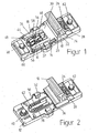
- FIG. 1-3 illustrated first embodiment of an arrangement for adjusting a tongue rail 11 to a stock rail 10 comprises in a known manner, for example, on a threshold or a fixed roadway arranged ribbed plate 12 and a tongue rail 11 supporting slide chair 14, the rod spring elements 16, 18 releasably on the ribbed plate 12 is arranged. It may be given a construction, as this of the WO-A-94/05858 it can be seen, the disclosure of which is expressly incorporated by reference.
- the slide chair 14 serves at the same time for fixing the stock rail 10 and is based in this case on a portion 20 of the foot 22 of the stock rail 10 from. Gleitstuhlferneauer section 24 of the foot 22 of the stock rail 10 is secured in the usual way, for example, by a clamping screw 26 fixable tension springs 28. In that regard, reference is made to well-known or alternative constructions.
- the slide chair 14 has a U-geometry, wherein transverse leg 30 extends directly along the stock rail 10 and rests on the underside on the section 20 of the rail foot 22.
- Side legs 32, 34 of the slide chair 14, which run along the longitudinal direction of the ribbed plate 12, ie transversely to the rails 10, 11, surround an insert 36 of the ribbed plate 12, which in turn is connected to the ribbed plate 12 via an elastic intermediate layer 38.
- the insert 36 is connected to the ribbed plate 12 by vulcanization.
- the insert 36 has a longitudinal slot 42, the width of which is selected such that within these rollers 44, 46 may extend, which extend from a holder 48 which is connected to the insert 36.
- the insert along the slot 42 and on its two sides receptacles 50, 52 as holes in which the holder 48 via screws 54, 56 can be fixed.
- the screws 54, 56 in the holder 48 pass through slots 58, 60, so that a continuous adjustment of the holder 48 and thus the roller elements 44, 46 can be made to the stock rail 10; because the slots 58, 60 are on the distance of the openings or holes 50, 52 in the insert 36 designed such that a stepless change in distance to the stock rail 10 is made possible.
- the bolts 40, 62 pass through existing inserts 64, 66, which are arranged in oblong holes, in dependence on the geometry or course of the opening for the bolt 40, 62 of the respective insert 64, 66 to allow an adjustment of the rib plate 12 along its longitudinal axis.
- inserts 64, 66 which are arranged in oblong holes, in dependence on the geometry or course of the opening for the bolt 40, 62 of the respective insert 64, 66 to allow an adjustment of the rib plate 12 along its longitudinal axis.
- well-known constructions such as these, for example, from DE-A-44 06 105 are known.
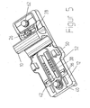
- Fig. 4 and 5 is a further embodiment of an arrangement for sliding change a tongue rail to refer to a stock rail. It will be in accordance with the Fig. 1 and 3 same reference numerals are used for the same elements.
Landscapes
- Engineering & Computer Science (AREA)
- Mechanical Engineering (AREA)
- Architecture (AREA)
- Civil Engineering (AREA)
- Structural Engineering (AREA)
- Railway Tracks (AREA)
- Chairs For Special Purposes, Such As Reclining Chairs (AREA)
- Saccharide Compounds (AREA)
- Steroid Compounds (AREA)
- Electrical Control Of Ignition Timing (AREA)
- Seats For Vehicles (AREA)
- Auxiliary Devices For And Details Of Packaging Control (AREA)
- Knitting Machines (AREA)
Description
- Die Erfindung bezieht sich auf eine Anordnung zum Umstellen einer Zungenschiene zu einer auf einer Unterlageplatte wie Rippenplatte fixierten Backenschiene umfassend einen von der auf einer Abstützung wie Schwelle oder festen Fahrbahn angeordneten Unterlageplatte ausgehenden Gleitstuhl sowie zumindest ein von einer Halterung ausgehendes Rollenelement, das Auflage zur die Zungenschiene ist.
- Eine entsprechende Anordnung ist der
EP-A- 0 964 100 zu entnehmen. Um eine entsprechende ein Rollenelement und eine Halterung umfassende Rolleneiririchtung universell einsetzen zu können ist vorgesehen, dass das Rollenelement sowohl in Höhe als auch im Abstand zur Backenschiene verstellbar ausgebildet ist. - Aus der
EP-B- 0 904 457 ist eine Vorrichtung zum Umstellen von Weichenzungen bekannt, die auf einer von einem Rollenpaar bereitgestellten Rollenebene eines Gleitstuhls aufliegt, wobei die vordere Rolle des Rollenpaars niedriger eingestellt ist als die hintere Rolle und zumindest eine Rolle auf einem Excenter als eine exzentrisch ausgebildete Rollenachse angeordnet ist. Hierdurch soll die Möglichkeit geschaffen werden, das Rollenelement in seiner Höhe einzustellen. Das Rollenpaar selbst ist ebenfalls zur Backenschiene verstellbar ausgebildet. Hierzu geht das Rollenpaar von einer entsprechenden Halterung aus. - Die bekannte Rolleneinrichtung ist derart mit der Rippenplatte verbunden, dass eine Mitbewegung erfolgt. Hierdurch kann es zu Schlägen auf die Zungenschiene insbesondere dann kommen, wenn Abhebewellen in die Backenschiene und somit auch in die Rippenplatte eingeleitet werden.
- Der vorliegenden Erfindung liegt das Problem zu Grunde, eine Anordnung der eingangs genannten Art so auszubilden, dass eine eindeutige Zuordnung des Rollenelementes zu der Backenschiene erfolgt, gleichzeitig jedoch sichergestellt ist, dass auf die Zungenschiene keine zu unkontrollierten Schlägen eihrenden Kräfte einleitbar sind.
- Erfindungsgemäß wird das Problem im Wesentlichen dadurch gelöst, dass die Halterung mit einem Einsatz in der Unterlageplatte lösbar verbunden ist und dass der Einsatz seinerseits randseitig über eine elastische Zwischenschicht mit der Unterlageplatte verbunden ist.
- Erfindungsgemäß geht die Halterung von einem Einsatz aus, der seinerseits elastisch mit der Unterlageplatte wie Rippenplatte verbunden ist- Hierdurch erfolgt quasi eine Entkopplung derart, dass beim Einleiten von zum Beispiel Abhebewellen in die Unterlageplatte diese nicht auf den Einsatz und somit auf die Halterung für das zumindest eine Rollenelement übertragen werden. Gleichzeitig sind besondere Befestigungsmittel für den Einsatz nicht erforderlich, da eine Fixierung zusammen mit der Unterlageplatte erfolgt.
- Insbesondere ist vorgesehen, dass das Rollenelement den Gleitstuhl durchsetzt, so dass sich eine kompakte Einheit ergibt; denn nach der
EP-B- 0 904 457 ist die Halterung für das Rollenelement neben dem GleitstuhI angeordnet, so dass zusätzliche Befestigungsmittel erforderlich sind. Ferner muss die Rippenplatte breiter als üblicherweise ausgebildet sein. - In Weiterbildung der Erfindung ist vorgesehen, dass der Einsatz in Richtung der Abstützung derart vorgespannt ist, dass dieser unabhängig von vertikaler Position der Unterlageplatte auf der Abstützung aufliegt. Dieses kann dadurch realisiert werden, dass der Einsatz von einem Befestigungselement wie Schraubbolzen durchsetzt ist, über die der Einsatz mit der Abstützung wie Schwelle oder feste Fahrbahn verbunden ist. Gleichzeitig erfolgt hierdurch eine Fixierung der Unterlageplatte wie Rippenplatte, da der Einsatz über die elastische Zwischenschicht mit der Unterlageplatte verbunden ist. Insbesondere erfolgt eine Verbindung zwischen dem Einsatz und der Unterlageplatte durch Vulkanisieren.
- Alternativ besteht auch die Möglichkeit, den Einsatz über die Unterlageplatte derart zu der Abstützung zu fixieren, dass der Einsatz stets flächig auf der Abstützung aufliegt, ohne dass der Einsatz selbst von einem Befestigungselement wie Schraubbolzen durchsetzt ist. Hierzu kann der Einsatz derart in die Unterlageplatte einvulkanisiert sein, dass im nicht eingebauten Zustand bodenseitige Fläche des Einsatzes über Bodenfläche der Unterlageplatte vorsteht. Wird sodann die Einheit Unterlageplatte/Einsatz auf der Abstützung wie Schwelle oder feste Fahrbahn befestigt, erfährt der Einsatz eine fortwährende Krafteinleitung in Richtung der Abstützung mit der Folge, dass auch dann, wenn auf die Unterlageplatte eine Abhebewelle einwirkt, also die Unterlageplatte vertikal verstellt wird, der Einsatz flächig auf der Abstützung aufliegt.
- Des Weiteren sollte der Einsatz einen in Längsrichtung der Unterlageplatte verlaufenden Schlitz aufweisen, innerhalb dem sich abschnittsweise das zumindest eine Rollenelement drehbar erstreckt. Insbesondere ist vorgesehen, dass der Schlitz in seiner Länge derart ausgelegt ist, dass zumindest zwei Rollenelemente in Längsrichtung der Unterlageplatte hintereinander angeordnet sind. Die Achsen der Rollenelemente verlaufen dabei in gewohnter Weise parallel oder in etwa parallel zur Längsachse der Backen- bzw. Zungenschiene.
- Entlang des Schlitzes, und zwar dessen Längsränder, sind Befestigungsaufnahmen vorgesehen, um die Halterung in Längsrichtung der Unterlageplatte verstellen zu können. Hierdurch ist sichergestellt, dass der Abstand zur Backenschiene im gewünschten Umfang verstellbar ist, um eine optimale Abstützung der Zungenschiene sicherzustellen.
- Um eine kompakte Anordnung zu ermöglichen, wird des Weiteren vorgeschlagen, dass der Gleitstuhl einen Ausschnitt aufweist, der zumindest abschnittsweise den Einsatz umgibt. Hierzu weist der Gleitstuhl insbesondere eine U-förmige Geometrie auf, wobei Seitenschenkel des Gleitstuhls entlang Längsränder des Einsatzes und insbesondere außerhalb von diesen verlaufen. Der Querschenkel selbst erstreckt sich unmittelbar entlang der Backenschiene.
- Weitere Einzelheiten, Vorteile und Merkmale der Erfindung ergeben sich nicht nur aus den Ansprüchen, den diesen zu entnehmenden Merkmalen -für sich und/oder in Kombination-, sondern auch aus der nachfolgenden Beschreibung eines der Zeichnung zu entnehmenden bevorzugten Ausführungsbeispiels.
- Es zeigen:
- Fig. 1
- eine perspektivische Darstellung einer ersten Ausführungsform einer Anordnung zum Umstellen einer Zungenschiene zu einer Backenschiene,
- Fig. 2
- die Anordnung gemäß
Fig. 1 , jedoch ohne Gleitstuhl und Rolleneinrichtung, - Fig. 3
- einen Längsschnitt durch die Anordnung gemäß
Fig. 1 , - Fig. 4
- eine perspektivische Darstellung einer zweiten Ausführungsform einer Anordnung zum Umstellen einer Zungenschiene und
- Fig. 5
- die Anordnung nach
Fig. 4 , jedoch ohne Gleitstuhl und Rolleneinrichtung. - Eine in den
Fig. 1 - 3 dargestellte erste Ausführungsform einer Anordnung zum Verstellen einer Zungenschiene 11 zu einer Backenschiene 10 umfasst in bekannter Weise eine zum Beispiel auf einer Schwelle oder einer festen Fahrbahn angeordnete Rippenplatte 12 sowie einen die Zungenschiene 11 abstützenden Gleitstuhl 14, der über Stabfederelemente 16, 18 lösbar auf der Rippenplatte 12 angeordnet ist. Dabei kann eine Konstruktion gegeben sein, wie diese derWO-A- 94/05858 - Der Gleitstuhl 14 weist eine U-Geometrie auf, wobei Querschenkel 30 unmittelbar entlang der Backenschiene 10 verläuft und unterseitig auf dem Abschnitt 20 des Schienenfußes 22 aufliegt. Seitenschenkel 32, 34 des Gleitstuhls 14, die entlang Längsrichtung der Rippenplatte 12, also quer zu den Schienen 10, 11 verlaufen, umgeben einen Einsatz 36 der Rippenplatte 12, der seinerseits über eine elastische Zwischenschicht 38 mit der Rippenplatte 12 verbunden ist. Insbesondere erfolgt eine Verbindung des Einsatzes 36 mit der Rippenplatte 12 durch Vulkanisieren.
- Der Einsatz 36 weist einen Längsschlitz 42 auf, dessen Breite derart gewählt ist, dass sich innerhalb von diesem Rollen 44, 46 erstrecken können, die von einer Halterung 48 ausgehen, die mit dem Einsatz 36 verbunden ist. Hierzu weist der Einsatz entlang des Schlitzes 42 und zu dessen beiden Seiten Aufnahmen 50, 52 wie Bohrungen auf, in die die Halterung 48 über Schrauben 54, 56 fixierbar ist. Dabei durchsetzen die Schrauben 54, 56 in der Halterung 48 vorhandene Langlöcher 58, 60, so dass ein stufenloses Verstellen der Halterung 48 und damit der Rollenelemente 44, 46 zu der Backenschiene 10 erfolgen kann; denn die Langlöcher 58, 60 sind auf den Abstand der Durchbrechungen bzw. Bohrungen 50, 52 in dem Einsatz 36 derart ausgelegt, dass eine stufenlose Abstandsveränderung zu der Backenschiene 10 ermöglicht wird.
- Dadurch, dass der Einsatz 36 mit der Rippenplatte 12 über die elastische Zwischenschicht 38 verbunden ist, erfolgt quasi eine Entkopplung, durch die sichergestellt ist, dass der Einsatz 36 stets auf der Abstützung wie Schwelle oder feste Fahrbahn aufliegt und somit die Halterung 48 für die Rollenelemente 44, 46 eine eindeutige Position einnimmt. Eine Mitbewegung mit der Rippenplatte 12 erfolgt demzufolge nicht bzw. dem Grunde nicht.
- In den Querrandbereichen der Rippenplatte 12 wird diese von Schraubbolzen 40, 62 durchsetzt, über die eine Verbindung mit der Abstützung erfolgt.
- Die Schraubbolzen 40, 62 durchsetzen dabei aus Kunststoff bestehende Einsätze 64, 66, die in Langlöchern angeordnet sind, um in Abhängigkeit von der Geometrie bzw. Verlauf der Durchbrechung für den Schraubbolzen 40, 62 des jeweiligen Einsatzes 64, 66 eine Verstellung der Rippenplatte 12 entlang deren Längsachse zu ermöglichen. Insoweit wird jedoch ebenfalls auf hinreichend bekannte Konstruktionen verwiesen, wie diese zum Beispiel aus der
DE-A- 44 06 105 bekannt sind. - Den
Fig. 4 und5 ist eine weitere Ausführungsform einer Anordnung zum gleitenden Umstellen einer Zungenschiene zu einer Backenschiene zu entnehmen. Dabei werden entsprechend denFig. 1 und3 für gleiche Elemente gleiche Bezugszeichen verwendet. - Das Ausführungsbeispiel der
Fig. 4 und5 , unterscheidet sich von dem derFig. 1 bis 3 dahingehend, dass die die Rippenplatte 12 mitsichernde Schraube 40 nicht beabstandet zu dem Einsatz 32 verläuft, sondern mit dem Einsatz 64 innerhalb des die Halterung 48 aufnehmenden Einsatzes 36 verläuft. Hierdurch besteht die Möglichkeit, dass über die Schraube 40 auf den Einsatz 36 eine Vorspannung eingeleitet wird. Diese bewirkt, dass die Zwischenlage 36 stets auf der Unterlage flächig aufliegt, und zwar unabhängig davon, ob die Rippenplatte 12 zum Beispiel durch Einleiten einer Abhebewelle eine Krafteinwirkung von der Unterlage weg erfährt. Die Rippenplatte 12 wird gleichfalls über die Schraube 40 mitfixiert, da der Einsatz 36 über die Zwischenschicht 38 mit der Rippenplatte 12 verbunden ist.
Claims (13)
- Anordnung zum Umstellen einer Zungenschiene (11) zu einer auf einer Unterlageplatte (12) wie Rippenplatte fixierten Backenschiene (10) umfassend einen von der auf einer Abstützung wie Schwelle oder festen Fahrbahn angeordneten Unterlageplatte ausgehenden Gleitstuhl (14) sowie zumindest ein von einer Halterung (48) ausgehendes Rollenelement (44, 46), das Auflage für die Zungenschiene ist,
dadurch gekennzeichnet,
dass die Halterung (48) mit einem Einsatz (36) in der Unterlageplatte (12) lösbar verbunden ist und dass der Einsatz seinerseits über eine elastische Zwischenschicht (38) randseitig mit der Unterlageplatte verbunden ist. - Anordnung nach Anspruch 1,
dadurch gekennzeichnet,
dass das Rollenelement (44, 46) den Gleitstuhl (14) durchsetzt. - Anordnung nach Anspruch 1,
dadurch gekennzeichnet,
dass der Einsatz (36) in Richtung der Abstützung derart vorgespannt ist, dass der Einsatz unabhängig von vertikaler Position der Unterlageplatte (12) auf der Abstützung aufliegt. - Anordnung nach Anspruch 1 oder 3,
dadurch gekennzeichnet,
dass der Einsatz (36) in die Unterlageplatte (12) derart einvulkanisiert ist, dass im uneingebauten Zustand der Unterlageplatte bodenseitige Fläche des Einsatzes über Bodenfläche der Unterlageplatte vorsteht. - Anordnung nach Anspruch 1,
dadurch gekennzeichnet,
dass der Einsatz (36) einen in Längsrichtung der Unterlageplatte (12) verlaufenden Schlitz (42) aufweist, innerhalb dem sich abschnittsweise das zumindest eine Rollenelement (44, 46) drehbar erstreckt. - Anordnung nach Anspruch 5,
dadurch gekennzeichnet,
dass entlang des Schlitzes (42) Befestigungsaufnahmen zum Verstellen der Halterung (48) in Längsrichtung der Unterlageplatte (12) angeordnet sind. - Anordnung nach Anspruch 6,
dadurch gekennzeichnet,
dass der Einsatz in Längsrichtung der Unterlageplatte (12) verlaufende Langlöcher (58, 60) aufweist, die von in die Befestigungsaufnahmen (50, 52) eingreifenden Befestigungselementen (54, 56) durchsetzt sind, wobei Abstand der Befestigungsaufnahmen (50, 52) in Längsrichtung der Unterlageplatte (12) und die Langlöcher (58, 60) derart aufeinander abgestimmt sind, dass ein stufenloses Verstellen der Halterung (48) zur Backenschiene (10) gegeben ist. - Anordnung nach Anspruch 1,
dadurch gekennzeichnet,
dass der Einsatz (36) von der Unterlageplatte (12) entkoppelt ist. - Anordnung nach Anspruch 1,
dadurch gekennzeichnet,
dass der Gleitstuhl (14) einen Ausschnitt aufweist, der zumindest abschnittsweise den Einsatz (36) umgibt. - Anordnung nach Anspruch 1,
dadurch gekennzeichnet,
dass der Gleitstuhl (14) eine U-förmige Geometrie aufweist und dass Seitenschenkel (43, 34) des Gleitstuhls entlang Längsrändern des Einsatzes (36) und insbesondere außerhalb dieser verlaufen. - Anordnung nach Anspruch 10,
dadurch gekennzeichnet,
dass Querschenkel (30) des Gleitstuhls (14) sich unmittelbar entlang der Backenschiene (10) erstreckt und sich auf dessen Fuß (22) abstützt. - Anordnung nach Anspruch 1,
dadurch gekennzeichnet,
dass ein die Unterlageplatte (12) sicherndes Befestigungselement wie Schraubbolzen (40) den Einsatz (36) durchsetzt, - Anordnung nach Anspruch 12,
dadurch gekennzeichnet,
dass das Befestigungselement wie Schraubbolzen (40) von einem zweiten Einsatz umgeben ist, der lösbar in einem quer zur Längsachse verlaufenden Langloch des die Halterung (48) aufnehmenden Einsatzes (36) angeordnet ist.
Applications Claiming Priority (3)
| Application Number | Priority Date | Filing Date | Title |
|---|---|---|---|
| DE10338114 | 2003-08-15 | ||
| DE102004013347A DE102004013347A1 (de) | 2003-08-15 | 2004-03-17 | Anordnung zum Umstellen einer Zungenschiene zu einer Backenschiene |
| PCT/EP2004/008805 WO2005017258A1 (de) | 2003-08-15 | 2004-08-06 | Anordnung zum umstellen einer zungenschiene zu einer backenschiene |
Publications (2)
| Publication Number | Publication Date |
|---|---|
| EP1654422A1 EP1654422A1 (de) | 2006-05-10 |
| EP1654422B1 true EP1654422B1 (de) | 2008-10-08 |
Family
ID=34195748
Family Applications (1)
| Application Number | Title | Priority Date | Filing Date |
|---|---|---|---|
| EP04763844A Expired - Lifetime EP1654422B1 (de) | 2003-08-15 | 2004-08-06 | Anordnung zum umstellen einer zungenschiene zu einer backenschiene |
Country Status (8)
| Country | Link |
|---|---|
| EP (1) | EP1654422B1 (de) |
| KR (1) | KR100859108B1 (de) |
| CN (1) | CN100582370C (de) |
| AT (1) | ATE410551T1 (de) |
| DE (2) | DE102004013347A1 (de) |
| ES (1) | ES2315686T3 (de) |
| TW (1) | TWI322842B (de) |
| WO (1) | WO2005017258A1 (de) |
Cited By (1)
| Publication number | Priority date | Publication date | Assignee | Title |
|---|---|---|---|---|
| EP2995718A1 (de) | 2014-09-10 | 2016-03-16 | Schwihag Ag | Rollvorrichtung zum umstellen einer weichenzunge |
Families Citing this family (12)
| Publication number | Priority date | Publication date | Assignee | Title |
|---|---|---|---|---|
| AT9061U1 (de) * | 2006-02-14 | 2007-04-15 | Vae Gmbh | Vorrichtung zum anheben einer zungenschiene |
| DE102007043325B4 (de) * | 2007-09-12 | 2009-07-23 | Bwg Gmbh & Co. Kg | Schienenauszugsvorrichtung |
| AT509055B1 (de) * | 2010-06-15 | 2011-06-15 | Vae Eisenbahnsysteme Gmbh | Vorrichtung zur befestigung einer backenschiene |
| DE102010025770A1 (de) * | 2010-07-01 | 2012-01-05 | Schwihag Ag | Rollvorrichtung für eine Zungenschiene einer Weiche |
| CN101914879B (zh) * | 2010-07-29 | 2011-12-21 | 中国铁建重工集团有限公司道岔分公司 | 一种道岔可动心轨辙叉垫板 |
| FR2979113B1 (fr) * | 2011-08-18 | 2013-08-16 | Vossloh Cogifer | Dispositif de positionnement de rouleaux pour systeme d'assistance a la manoeuvre |
| CN103132400B (zh) * | 2013-03-20 | 2015-01-07 | 中国铁建重工集团有限公司 | 一种用于道岔转辙器的滑动装置 |
| CN103806350B (zh) * | 2014-03-11 | 2015-12-09 | 中国铁建重工集团有限公司 | 一种便于调整的辊轮结构 |
| DE102016111210A1 (de) * | 2016-06-20 | 2017-12-21 | Voestalpine Bwg Gmbh | Anordnung zum Umstellen einer Zungenschiene |
| DE102018117453A1 (de) | 2018-07-19 | 2020-01-23 | Schwihag Ag Gleis- Und Weichentechnik | Schienenbefestigungssystem |
| JP7349721B2 (ja) * | 2019-11-14 | 2023-09-25 | 鉄道機器株式会社 | 床板 |
| US12359377B1 (en) | 2024-04-10 | 2025-07-15 | voestalpine Railway Systems Nortrak LLC | Switch point roller assembly |
Family Cites Families (9)
| Publication number | Priority date | Publication date | Assignee | Title |
|---|---|---|---|---|
| DE1142378B (de) * | 1961-03-28 | 1963-01-17 | Kloeckner Werke Ag | Gleitstuhl fuer Zungenvorrichtungen von Weichen |
| DE9109182U1 (de) | 1991-07-25 | 1991-11-14 | BWG Butzbacher Weichenbau GmbH, 6308 Butzbach | Rolleinrichtung für eine einer Backenschiene zugeordneten Zunge einer Weiche |
| DE4223095C2 (de) * | 1992-07-14 | 1995-08-31 | Harald Huefner | Lagerung für eine Schienenweiche mit einem Schienenpaar und zwei Weichenzungen |
| DE59305133D1 (de) * | 1992-10-16 | 1997-02-27 | Vae Ag | Einrichtung zum Erleichtern der Umstellbewegung von beweglichen Schienen oder Schienenteilen |
| DE4405115A1 (de) * | 1994-02-17 | 1995-08-24 | Butzbacher Weichenbau Gmbh | Rolleneinrichtung |
| DE4410086C2 (de) * | 1994-03-23 | 1997-08-21 | Krupp Ag Hoesch Krupp | Rollvorrichtung für eine Weichenkonstruktion bei Eisenbahnen im Gleisoberbau |
| DE19623269A1 (de) * | 1996-06-11 | 1997-12-18 | Schwihag Gmbh | Weichenzungen |
| KR200197806Y1 (ko) | 2000-05-04 | 2000-09-15 | 박장묵 | 철도 분기기용 베이스 플레이트 |
| JP2002004203A (ja) * | 2000-06-22 | 2002-01-09 | West Japan Railway Co | 転てつ減摩器 |
-
2004
- 2004-03-17 DE DE102004013347A patent/DE102004013347A1/de not_active Withdrawn
- 2004-08-06 AT AT04763844T patent/ATE410551T1/de active
- 2004-08-06 CN CN200480023331A patent/CN100582370C/zh not_active Expired - Fee Related
- 2004-08-06 KR KR1020067001611A patent/KR100859108B1/ko not_active Expired - Fee Related
- 2004-08-06 DE DE502004008223T patent/DE502004008223D1/de not_active Expired - Lifetime
- 2004-08-06 WO PCT/EP2004/008805 patent/WO2005017258A1/de not_active Ceased
- 2004-08-06 EP EP04763844A patent/EP1654422B1/de not_active Expired - Lifetime
- 2004-08-06 ES ES04763844T patent/ES2315686T3/es not_active Expired - Lifetime
- 2004-08-13 TW TW093124373A patent/TWI322842B/zh not_active IP Right Cessation
Cited By (2)
| Publication number | Priority date | Publication date | Assignee | Title |
|---|---|---|---|---|
| EP2995718A1 (de) | 2014-09-10 | 2016-03-16 | Schwihag Ag | Rollvorrichtung zum umstellen einer weichenzunge |
| EA028810B1 (ru) * | 2014-09-10 | 2018-01-31 | Швихаг Аг | Роликовое устройство для перестановки остряка стрелки |
Also Published As
| Publication number | Publication date |
|---|---|
| TW200513574A (en) | 2005-04-16 |
| WO2005017258A1 (de) | 2005-02-24 |
| TWI322842B (en) | 2010-04-01 |
| EP1654422A1 (de) | 2006-05-10 |
| HK1091877A1 (zh) | 2007-01-26 |
| DE102004013347A1 (de) | 2005-04-14 |
| CN1836073A (zh) | 2006-09-20 |
| KR20060111903A (ko) | 2006-10-30 |
| ES2315686T3 (es) | 2009-04-01 |
| KR100859108B1 (ko) | 2008-09-18 |
| CN100582370C (zh) | 2010-01-20 |
| ATE410551T1 (de) | 2008-10-15 |
| DE502004008223D1 (de) | 2008-11-20 |
Similar Documents
| Publication | Publication Date | Title |
|---|---|---|
| EP1654422B1 (de) | Anordnung zum umstellen einer zungenschiene zu einer backenschiene | |
| EP1759062B1 (de) | Anordnung zum befestigen einer schiene | |
| DE202006020567U1 (de) | System zur Befestigung einer Schiene | |
| EP2478154A1 (de) | System zum befestigen einer schiene und befestigung einer schiene | |
| DE102009052581B4 (de) | Fahrzeugsitz, insbesondere Kraftfahrzeugsitz | |
| EP0987368B1 (de) | Vorrichtung zum Befestigen von Radlenkern | |
| DE60019286T2 (de) | Verstellbare eisenbahnschienenbefestigung und verfahren zu deren verwendung | |
| DE10310018A1 (de) | Vorrichtung zum Befestigen eines Gurtschlosses eines Sicherheitsgurtes an einem Fahrzeugsitz | |
| DE60020761T2 (de) | Träger für Fahrzeugsitze | |
| DE3141158A1 (de) | Fuehrungsvorrichtung fuer einen ein- und ausfahrbaren einsatz im korpus einer dentaleinrichtung | |
| DE10157676A1 (de) | Einrichtung zum seitlichen Abstützen einer Schiene | |
| EP3472386B1 (de) | Anordnung zum umstellen einer zungenschiene | |
| EP0455236B1 (de) | Schienenbefestigungsmittel | |
| DE202022104870U1 (de) | Glasträgerelement mit montageseitig und fallseitig verschiebbaren Innenkeilen | |
| EP1508642A1 (de) | Vorrichtung zum Befestigen einer Schiene | |
| DE4421678B4 (de) | Befestigungs- und Haltevorrichtung für Gleisbauschutzabgrenzungen | |
| EP0778372B1 (de) | Gleitstuhl | |
| DE202004004703U1 (de) | Rahmen für eine Tür, ein Fenster o.dgl. | |
| EP0690940B1 (de) | Schienenanordnung | |
| EP1221506B1 (de) | Stützpunkt für eine Schiene | |
| DE4202443A1 (de) | Schneepflug | |
| EP1052330A2 (de) | Abstützung für eine erste Schiene wie Zungenschiene | |
| DE202024103142U1 (de) | Vorrichtung zur Befestigung einer senkrecht ausgerichteten Geländerplatte durch Verkeilung zwischen den Innenwandungen des Führungskanals eines Bodenträgerprofils | |
| DE2221132C3 (de) | Verstellbeschlag zur einstellbaren Befestigung der Frontplatte eines ausziehbaren Möbelteils | |
| DE202022104868U1 (de) | Fallseitige Komponente eines Glasträgerelement mit unabhängiger montageseitiger Einstellung und Fixierung |
Legal Events
| Date | Code | Title | Description |
|---|---|---|---|
| PUAI | Public reference made under article 153(3) epc to a published international application that has entered the european phase |
Free format text: ORIGINAL CODE: 0009012 |
|
| 17P | Request for examination filed |
Effective date: 20051109 |
|
| AK | Designated contracting states |
Kind code of ref document: A1 Designated state(s): AT BE BG CH CY CZ DE DK EE ES FI FR GB GR HU IE IT LI LU MC NL PL PT RO SE SI SK TR |
|
| DAX | Request for extension of the european patent (deleted) | ||
| REG | Reference to a national code |
Ref country code: HK Ref legal event code: DE Ref document number: 1091877 Country of ref document: HK |
|
| RIN1 | Information on inventor provided before grant (corrected) |
Inventor name: BUDNITZKI, GRIGORI Inventor name: DIETZE, HANS-ULRICH |
|
| 17Q | First examination report despatched |
Effective date: 20070328 |
|
| GRAP | Despatch of communication of intention to grant a patent |
Free format text: ORIGINAL CODE: EPIDOSNIGR1 |
|
| GRAS | Grant fee paid |
Free format text: ORIGINAL CODE: EPIDOSNIGR3 |
|
| RAP1 | Party data changed (applicant data changed or rights of an application transferred) |
Owner name: VAE GMBH Owner name: VOESTALPINE BWG GMBH & CO.KG |
|
| GRAA | (expected) grant |
Free format text: ORIGINAL CODE: 0009210 |
|
| AK | Designated contracting states |
Kind code of ref document: B1 Designated state(s): AT BE BG CH CY CZ DE DK EE ES FI FR GB GR HU IE IT LI LU MC NL PL PT RO SE SI SK TR |
|
| REG | Reference to a national code |
Ref country code: GB Ref legal event code: FG4D Free format text: NOT ENGLISH |
|
| REG | Reference to a national code |
Ref country code: CH Ref legal event code: EP |
|
| REG | Reference to a national code |
Ref country code: IE Ref legal event code: FG4D Free format text: LANGUAGE OF EP DOCUMENT: GERMAN |
|
| REF | Corresponds to: |
Ref document number: 502004008223 Country of ref document: DE Date of ref document: 20081120 Kind code of ref document: P |
|
| RAP2 | Party data changed (patent owner data changed or rights of a patent transferred) |
Owner name: VAE GMBH Owner name: VOESTALPINE BWG GMBH & CO.KG Owner name: SCHWIHAG AG GLEIS- UND WEICHENTECHNIK |
|
| REG | Reference to a national code |
Ref country code: GR Ref legal event code: EP Ref document number: 20090400018 Country of ref document: GR |
|
| RAP2 | Party data changed (patent owner data changed or rights of a patent transferred) |
Owner name: SCHWIHAG AG GLEIS- UND WEICHENTECHNIK Owner name: VAE GMBH Owner name: VOESTALPINE BWG GMBH & CO.KG |
|
| PG25 | Lapsed in a contracting state [announced via postgrant information from national office to epo] |
Ref country code: SI Free format text: LAPSE BECAUSE OF FAILURE TO SUBMIT A TRANSLATION OF THE DESCRIPTION OR TO PAY THE FEE WITHIN THE PRESCRIBED TIME-LIMIT Effective date: 20081008 |
|
| RAP2 | Party data changed (patent owner data changed or rights of a patent transferred) |
Owner name: SCHWIHAG AG GLEIS- UND WEICHENTECHNIK Owner name: VAE GMBH Owner name: VOESTALPINE BWG GMBH & CO.KG |
|
| REG | Reference to a national code |
Ref country code: ES Ref legal event code: FG2A Ref document number: 2315686 Country of ref document: ES Kind code of ref document: T3 |
|
| PG25 | Lapsed in a contracting state [announced via postgrant information from national office to epo] |
Ref country code: BG Free format text: LAPSE BECAUSE OF FAILURE TO SUBMIT A TRANSLATION OF THE DESCRIPTION OR TO PAY THE FEE WITHIN THE PRESCRIBED TIME-LIMIT Effective date: 20090108 |
|
| NLT2 | Nl: modifications (of names), taken from the european patent patent bulletin |
Owner name: VOESTALPINE BWG GMBH & CO.KG EN VAE GMBH Effective date: 20090225 |
|
| PG25 | Lapsed in a contracting state [announced via postgrant information from national office to epo] |
Ref country code: PT Free format text: LAPSE BECAUSE OF FAILURE TO SUBMIT A TRANSLATION OF THE DESCRIPTION OR TO PAY THE FEE WITHIN THE PRESCRIBED TIME-LIMIT Effective date: 20090218 Ref country code: PL Free format text: LAPSE BECAUSE OF FAILURE TO SUBMIT A TRANSLATION OF THE DESCRIPTION OR TO PAY THE FEE WITHIN THE PRESCRIBED TIME-LIMIT Effective date: 20081008 Ref country code: FI Free format text: LAPSE BECAUSE OF FAILURE TO SUBMIT A TRANSLATION OF THE DESCRIPTION OR TO PAY THE FEE WITHIN THE PRESCRIBED TIME-LIMIT Effective date: 20081008 |
|
| NLT2 | Nl: modifications (of names), taken from the european patent patent bulletin |
Owner name: VOESTALPINE BWG GMBH & CO.KG EN VAE GMBH EN SCHWIH Effective date: 20090401 |
|
| REG | Reference to a national code |
Ref country code: HK Ref legal event code: GR Ref document number: 1091877 Country of ref document: HK |
|
| REG | Reference to a national code |
Ref country code: IE Ref legal event code: FD4D |
|
| PG25 | Lapsed in a contracting state [announced via postgrant information from national office to epo] |
Ref country code: RO Free format text: LAPSE BECAUSE OF FAILURE TO SUBMIT A TRANSLATION OF THE DESCRIPTION OR TO PAY THE FEE WITHIN THE PRESCRIBED TIME-LIMIT Effective date: 20081008 Ref country code: IE Free format text: LAPSE BECAUSE OF FAILURE TO SUBMIT A TRANSLATION OF THE DESCRIPTION OR TO PAY THE FEE WITHIN THE PRESCRIBED TIME-LIMIT Effective date: 20081008 Ref country code: EE Free format text: LAPSE BECAUSE OF FAILURE TO SUBMIT A TRANSLATION OF THE DESCRIPTION OR TO PAY THE FEE WITHIN THE PRESCRIBED TIME-LIMIT Effective date: 20081008 Ref country code: DK Free format text: LAPSE BECAUSE OF FAILURE TO SUBMIT A TRANSLATION OF THE DESCRIPTION OR TO PAY THE FEE WITHIN THE PRESCRIBED TIME-LIMIT Effective date: 20081008 |
|
| NLS | Nl: assignments of ep-patents |
Owner name: VAE GMBH Effective date: 20090528 Owner name: SCHWIHAG AG GLEIS- UND WEICHENTECHNIK Effective date: 20090528 Owner name: VOESTALPINE BWG GMBH & CO.KG Effective date: 20090528 |
|
| PLBE | No opposition filed within time limit |
Free format text: ORIGINAL CODE: 0009261 |
|
| STAA | Information on the status of an ep patent application or granted ep patent |
Free format text: STATUS: NO OPPOSITION FILED WITHIN TIME LIMIT |
|
| PG25 | Lapsed in a contracting state [announced via postgrant information from national office to epo] |
Ref country code: SE Free format text: LAPSE BECAUSE OF FAILURE TO SUBMIT A TRANSLATION OF THE DESCRIPTION OR TO PAY THE FEE WITHIN THE PRESCRIBED TIME-LIMIT Effective date: 20090108 Ref country code: CZ Free format text: LAPSE BECAUSE OF FAILURE TO SUBMIT A TRANSLATION OF THE DESCRIPTION OR TO PAY THE FEE WITHIN THE PRESCRIBED TIME-LIMIT Effective date: 20081008 |
|
| 26N | No opposition filed |
Effective date: 20090709 |
|
| PG25 | Lapsed in a contracting state [announced via postgrant information from national office to epo] |
Ref country code: SK Free format text: LAPSE BECAUSE OF FAILURE TO SUBMIT A TRANSLATION OF THE DESCRIPTION OR TO PAY THE FEE WITHIN THE PRESCRIBED TIME-LIMIT Effective date: 20081008 |
|
| REG | Reference to a national code |
Ref country code: FR Ref legal event code: TQ |
|
| BERE | Be: lapsed |
Owner name: VAE GMBH Effective date: 20090831 Owner name: VOESTALPINE BWG G.M.B.H. & CO.KG Effective date: 20090831 |
|
| PG25 | Lapsed in a contracting state [announced via postgrant information from national office to epo] |
Ref country code: MC Free format text: LAPSE BECAUSE OF NON-PAYMENT OF DUE FEES Effective date: 20090831 |
|
| PG25 | Lapsed in a contracting state [announced via postgrant information from national office to epo] |
Ref country code: BE Free format text: LAPSE BECAUSE OF NON-PAYMENT OF DUE FEES Effective date: 20090831 |
|
| PG25 | Lapsed in a contracting state [announced via postgrant information from national office to epo] |
Ref country code: HU Free format text: LAPSE BECAUSE OF FAILURE TO SUBMIT A TRANSLATION OF THE DESCRIPTION OR TO PAY THE FEE WITHIN THE PRESCRIBED TIME-LIMIT Effective date: 20090409 |
|
| PG25 | Lapsed in a contracting state [announced via postgrant information from national office to epo] |
Ref country code: CY Free format text: LAPSE BECAUSE OF FAILURE TO SUBMIT A TRANSLATION OF THE DESCRIPTION OR TO PAY THE FEE WITHIN THE PRESCRIBED TIME-LIMIT Effective date: 20081008 |
|
| PGFP | Annual fee paid to national office [announced via postgrant information from national office to epo] |
Ref country code: GR Payment date: 20110822 Year of fee payment: 8 |
|
| REG | Reference to a national code |
Ref country code: GR Ref legal event code: ML Ref document number: 20090400018 Country of ref document: GR Effective date: 20130304 |
|
| PG25 | Lapsed in a contracting state [announced via postgrant information from national office to epo] |
Ref country code: GR Free format text: LAPSE BECAUSE OF NON-PAYMENT OF DUE FEES Effective date: 20130304 |
|
| REG | Reference to a national code |
Ref country code: FR Ref legal event code: PLFP Year of fee payment: 13 |
|
| REG | Reference to a national code |
Ref country code: FR Ref legal event code: PLFP Year of fee payment: 14 |
|
| REG | Reference to a national code |
Ref country code: FR Ref legal event code: PLFP Year of fee payment: 15 |
|
| PGFP | Annual fee paid to national office [announced via postgrant information from national office to epo] |
Ref country code: LU Payment date: 20190821 Year of fee payment: 16 |
|
| PGFP | Annual fee paid to national office [announced via postgrant information from national office to epo] |
Ref country code: FR Payment date: 20190822 Year of fee payment: 16 |
|
| PG25 | Lapsed in a contracting state [announced via postgrant information from national office to epo] |
Ref country code: LU Free format text: LAPSE BECAUSE OF NON-PAYMENT OF DUE FEES Effective date: 20200806 |
|
| PG25 | Lapsed in a contracting state [announced via postgrant information from national office to epo] |
Ref country code: FR Free format text: LAPSE BECAUSE OF NON-PAYMENT OF DUE FEES Effective date: 20200831 |
|
| PGFP | Annual fee paid to national office [announced via postgrant information from national office to epo] |
Ref country code: CH Payment date: 20210917 Year of fee payment: 18 |
|
| PGFP | Annual fee paid to national office [announced via postgrant information from national office to epo] |
Ref country code: NL Payment date: 20220822 Year of fee payment: 19 |
|
| PGFP | Annual fee paid to national office [announced via postgrant information from national office to epo] |
Ref country code: TR Payment date: 20220803 Year of fee payment: 19 Ref country code: IT Payment date: 20220825 Year of fee payment: 19 Ref country code: GB Payment date: 20220822 Year of fee payment: 19 Ref country code: DE Payment date: 20220620 Year of fee payment: 19 Ref country code: AT Payment date: 20220822 Year of fee payment: 19 |
|
| PGFP | Annual fee paid to national office [announced via postgrant information from national office to epo] |
Ref country code: ES Payment date: 20221024 Year of fee payment: 19 |
|
| REG | Reference to a national code |
Ref country code: CH Ref legal event code: PL |
|
| PG25 | Lapsed in a contracting state [announced via postgrant information from national office to epo] |
Ref country code: LI Free format text: LAPSE BECAUSE OF NON-PAYMENT OF DUE FEES Effective date: 20220831 Ref country code: CH Free format text: LAPSE BECAUSE OF NON-PAYMENT OF DUE FEES Effective date: 20220831 |
|
| REG | Reference to a national code |
Ref country code: DE Ref legal event code: R119 Ref document number: 502004008223 Country of ref document: DE |
|
| REG | Reference to a national code |
Ref country code: NL Ref legal event code: MM Effective date: 20230901 |
|
| REG | Reference to a national code |
Ref country code: AT Ref legal event code: MM01 Ref document number: 410551 Country of ref document: AT Kind code of ref document: T Effective date: 20230806 |
|
| PG25 | Lapsed in a contracting state [announced via postgrant information from national office to epo] |
Ref country code: AT Free format text: LAPSE BECAUSE OF NON-PAYMENT OF DUE FEES Effective date: 20230806 |
|
| GBPC | Gb: european patent ceased through non-payment of renewal fee |
Effective date: 20230806 |
|
| PG25 | Lapsed in a contracting state [announced via postgrant information from national office to epo] |
Ref country code: AT Free format text: LAPSE BECAUSE OF NON-PAYMENT OF DUE FEES Effective date: 20230806 |
|
| PG25 | Lapsed in a contracting state [announced via postgrant information from national office to epo] |
Ref country code: NL Free format text: LAPSE BECAUSE OF NON-PAYMENT OF DUE FEES Effective date: 20230901 |
|
| PG25 | Lapsed in a contracting state [announced via postgrant information from national office to epo] |
Ref country code: NL Free format text: LAPSE BECAUSE OF NON-PAYMENT OF DUE FEES Effective date: 20230901 |
|
| PG25 | Lapsed in a contracting state [announced via postgrant information from national office to epo] |
Ref country code: GB Free format text: LAPSE BECAUSE OF NON-PAYMENT OF DUE FEES Effective date: 20230806 |
|
| PG25 | Lapsed in a contracting state [announced via postgrant information from national office to epo] |
Ref country code: IT Free format text: LAPSE BECAUSE OF NON-PAYMENT OF DUE FEES Effective date: 20230806 Ref country code: GB Free format text: LAPSE BECAUSE OF NON-PAYMENT OF DUE FEES Effective date: 20230806 Ref country code: DE Free format text: LAPSE BECAUSE OF NON-PAYMENT OF DUE FEES Effective date: 20240301 |
|
| REG | Reference to a national code |
Ref country code: ES Ref legal event code: FD2A Effective date: 20240927 |
|
| PG25 | Lapsed in a contracting state [announced via postgrant information from national office to epo] |
Ref country code: ES Free format text: LAPSE BECAUSE OF NON-PAYMENT OF DUE FEES Effective date: 20230807 |
|
| PG25 | Lapsed in a contracting state [announced via postgrant information from national office to epo] |
Ref country code: ES Free format text: LAPSE BECAUSE OF NON-PAYMENT OF DUE FEES Effective date: 20230807 |