EP1653174A2 - Eisherstellung und Abgabesystem - Google Patents
Eisherstellung und Abgabesystem Download PDFInfo
- Publication number
- EP1653174A2 EP1653174A2 EP20050109774 EP05109774A EP1653174A2 EP 1653174 A2 EP1653174 A2 EP 1653174A2 EP 20050109774 EP20050109774 EP 20050109774 EP 05109774 A EP05109774 A EP 05109774A EP 1653174 A2 EP1653174 A2 EP 1653174A2
- Authority
- EP
- European Patent Office
- Prior art keywords
- ice
- dispenser
- lifter
- cubes
- storage bin
- Prior art date
- Legal status (The legal status is an assumption and is not a legal conclusion. Google has not performed a legal analysis and makes no representation as to the accuracy of the status listed.)
- Granted
Links
- 238000003860 storage Methods 0.000 claims description 124
- 230000007246 mechanism Effects 0.000 claims description 10
- XLYOFNOQVPJJNP-UHFFFAOYSA-N water Substances O XLYOFNOQVPJJNP-UHFFFAOYSA-N 0.000 description 57
- 230000003028 elevating effect Effects 0.000 description 7
- 230000005484 gravity Effects 0.000 description 7
- 238000001816 cooling Methods 0.000 description 6
- 238000000034 method Methods 0.000 description 6
- DIYWRNLYKJKHAM-MDOVXXIYSA-N (-)-cubebin Chemical compound C1=C2OCOC2=CC(C[C@@H]2[C@@H](CC=3C=C4OCOC4=CC=3)CO[C@@H]2O)=C1 DIYWRNLYKJKHAM-MDOVXXIYSA-N 0.000 description 5
- XUEHVOLRMXNRKQ-KHMAMNHCSA-N alpha cubebene Natural products CC(C)[C@@H]([C@H]12)CC[C@@H](C)[C@]32[C@@H]1C(C)=CC3 XUEHVOLRMXNRKQ-KHMAMNHCSA-N 0.000 description 5
- 238000003825 pressing Methods 0.000 description 5
- 238000004891 communication Methods 0.000 description 4
- 239000011521 glass Substances 0.000 description 4
- 230000004913 activation Effects 0.000 description 3
- 238000002844 melting Methods 0.000 description 3
- 230000008018 melting Effects 0.000 description 3
- 230000004044 response Effects 0.000 description 3
- 239000002826 coolant Substances 0.000 description 2
- 238000007710 freezing Methods 0.000 description 2
- 238000003306 harvesting Methods 0.000 description 2
- 238000009413 insulation Methods 0.000 description 2
- 238000012546 transfer Methods 0.000 description 2
- 238000009423 ventilation Methods 0.000 description 2
- JOYRKODLDBILNP-UHFFFAOYSA-N Ethyl urethane Chemical compound CCOC(N)=O JOYRKODLDBILNP-UHFFFAOYSA-N 0.000 description 1
- 230000003213 activating effect Effects 0.000 description 1
- 230000015572 biosynthetic process Effects 0.000 description 1
- 238000000151 deposition Methods 0.000 description 1
- 238000007599 discharging Methods 0.000 description 1
- 238000005516 engineering process Methods 0.000 description 1
- 230000008014 freezing Effects 0.000 description 1
- 235000011389 fruit/vegetable juice Nutrition 0.000 description 1
- 229910000078 germane Inorganic materials 0.000 description 1
- 239000000463 material Substances 0.000 description 1
- 230000004048 modification Effects 0.000 description 1
- 238000012986 modification Methods 0.000 description 1
- 239000002245 particle Substances 0.000 description 1
- 230000008569 process Effects 0.000 description 1
- 238000005057 refrigeration Methods 0.000 description 1
- 238000007789 sealing Methods 0.000 description 1
- 230000007704 transition Effects 0.000 description 1
- 238000013519 translation Methods 0.000 description 1
Images


Classifications
-
- F—MECHANICAL ENGINEERING; LIGHTING; HEATING; WEAPONS; BLASTING
- F25—REFRIGERATION OR COOLING; COMBINED HEATING AND REFRIGERATION SYSTEMS; HEAT PUMP SYSTEMS; MANUFACTURE OR STORAGE OF ICE; LIQUEFACTION SOLIDIFICATION OF GASES
- F25C—PRODUCING, WORKING OR HANDLING ICE
- F25C5/00—Working or handling ice
- F25C5/18—Storing ice
- F25C5/182—Ice bins therefor
-
- F—MECHANICAL ENGINEERING; LIGHTING; HEATING; WEAPONS; BLASTING
- F25—REFRIGERATION OR COOLING; COMBINED HEATING AND REFRIGERATION SYSTEMS; HEAT PUMP SYSTEMS; MANUFACTURE OR STORAGE OF ICE; LIQUEFACTION SOLIDIFICATION OF GASES
- F25C—PRODUCING, WORKING OR HANDLING ICE
- F25C5/00—Working or handling ice
- F25C5/20—Distributing ice
- F25C5/22—Distributing ice particularly adapted for household refrigerators
Definitions
- the invention relates to an ice making and dispensing system.
- the invention relates to a bottom-mount refrigerator comprising a freezer-mounted ice maker and an ice cube lifter for delivering ice cubes to a dispenser mounted in the refrigerator compartment door.
- the invention relates to an under-the-counter ice maker having an ice cube lifter for delivering ice cubes to above-the-counter dispenser outlet.
- a bottom-mount refrigerator in which the refrigerated compartment is located above the freezer compartment
- a top-mount refrigerator in which the freezer compartment is located above the refrigerated compartment
- a side-by-side refrigerator in which the refrigerated compartment and freezer compartment extend the entire height of the refrigerator.
- the bottom-mount configuration is considered by many consumers to have the most convenient configuration since most consumers access the refrigerated compartment of a refrigerator far more frequently than the freezer compartment.
- the upper position of the refrigerated compartment in a bottom-mount configuration positions the majority of the contents of the refrigerated compartment at the standing height of the consumer, negating the need for the consumer to stoop or bend over to see or select items. Therefore, a combination refrigerator with the freezer on the bottom provides the user with the greatest convenience by providing the maximum fresh food compartment space at eye-level and within easy reach.
- a through-the-door ice and water dispenser is desirable because it greatly simplifies the process of retrieving ice cubes, i.e. it eliminates opening the door, removing the ice storage container, separating and scooping ice cubes, and pouring the ice cubes into a glass.
- the feature also is viewed as an energy saver, since the freezer door is not opened as often.
- the side-by-side configuration offers a through-the-door ice and water system.
- the side-by-side configuration is best suited for through-the-door ice dispensing because the freezer door extends the height of the refrigerator cabinet, which permits the ice dispenser to be located in the freezer door at a height convenient for the user.
- the top-mount and bottom-mount refrigerators have freezer door locations that would place the ice dispenser either too high or too low for convenient use by the consumer.
- locating the ice dispenser in a bottom-mount refrigerator involves two problems that must be overcome. First, if ice is made and/or stored in the refrigerated compartment, it will melt if not insulated from and chilled independently of the refrigerated compartment. Second, if ice is made and/or stored in the freezer compartment, it must be transported upwardly for dispensing through the ice and water dispenser.
- Undercounter ice makers are a desirable addition to kitchens and entertainment centers in homes.
- undercounter ice makers for home use have not been available with dispensers for dispensing ice at the countertop level.
- the invention relates to an appliance for making and dispensing ice cubes having an ice maker compartment including an ice maker for generating ice cubes, a dispenser outlet located above the ice maker compartment and an ice dispenser operably connecting the ice maker to the dispenser outlet.
- the ice dispenser includes a lifter positioned outside the ice maker compartment for moving ice cubes toward the dispenser outlet.
- the appliance can include an ice cube storage bin.
- the lifter includes an outlet through which ice cubes are expelled from the lifter.
- the lifter outlet can be directly connected to the dispenser outlet to directly dispense ice cubes to the dispenser outlet.
- the lifter outlet can be connected to a dispenser mechanism arranged to dispense ice cubes and crushed ice.
- the ice cube storage bin can be located adjacent the dispenser outlet.
- the lifter outlet can be connected to the ice cube storage bin such that the lifter moves the ice cubes to the ice cube storage bin for storage prior to dispensing through the dispenser outlet.
- the ice cube storage bin can be positioned to receive ice cubes from the ice maker and the lifter extends from the ice cube storage bin to the dispenser outlet.
- the lifter can be positioned outside the ice cube storage bin.
- the lifter can comprise an elevator having a lifting platform that is movable between a loading position where ice cubes can be loaded onto the platform and a dispensing position where the ice cubes are positioned for dispensing through the dispenser outlet.
- the dispenser can include a deflector to deflect ice cubes carried by the platform to the dispenser outlet.
- the deflector can be a stripper having multiple teeth and the lifting platform can have multiple openings corresponding to the teeth. The teeth are received within the openings as the platform is lifted to strip ice cubes off the platform.
- the lifter can comprise an auger.
- the auger can be helical.
- the lifter can comprise a conveyor.
- the conveyor can comprise an endless belt with at least one projection extending from the belt for supporting at least one ice cube.
- the lifter can comprise an accelerator that propels ice cubes toward the dispenser outlet.
- the lifter can include a conduit extending toward the dispenser outlet and the accelerator propels the ice cubes with sufficient velocity to carry ice cubes to the dispenser outlet.
- the conduit can include a return conduit for ice cubes falling back down the conduit.
- the accelerator can comprise a rotatable impeller having at least one blade to contact and propel ice cubes.
- the appliance can be an undercounter freezer and the dispenser outlet is positioned on a countertop above the freezer.
- the dispenser includes a lifter extending from adjacent the freezer compartment to the dispenser outlet.
- the appliance can be a bottom freezer refrigerator having a refrigerator compartment maintained at a temperature above 0°C.
- the dispenser outlet is positioned on the refrigerator compartment door and the ice maker is positioned in the freezer compartment.
- An ice cube storage bin can be located in the freezer compartment and the lifter can carry ice cubes from the ice cube storage bin to the dispenser outlet.
- the ice cube storage bin can be located on the refrigerator compartment door and the lifter can carry ice cubes from the ice maker to the ice cube storage bin.
- the lifter can extend along the wall of the refrigerator compartment and the freezer compartment.
- a connector can lead from the lifter outlet to the dispenser outlet.
- the appliance can be an undercounter ice maker and the dispenser outlet can be positioned on the countertop above the undercounter ice maker.
- the undercounter ice maker can include an ice cube storage bin and the lifter can be positioned adjacent the undercounter ice maker and can be connected to the ice cube storage bin.
- the lifter can be an elevator having a lifting platform that is movable between a loading position where ice cubes are loaded from the ice cube storage bin and a dispensing position where ice cubes are positioned for dispensing from the dispenser outlet.
- the lifter can include a deflector comprising a stripper to remove ice cubes from the platform at the dispensing position.
- the lifter can be an accelerator having a conduit extending toward the dispenser outlet.
- the accelerator propels ice cubes into the conduit with sufficient velocity to carry the ice cubes to the dispenser outlet.
- the undercounter ice maker can include a mover in the ice cube storage bin to move ice cubes to the accelerator inlet.
- the undercounter ice maker can include a drain and the conduit can include a return duct with an inlet in the conduit.
- the conduit can include a baffle movable between a first position where in blocks ice cubes from entering the return duct while leaving the conduit open and a second position where it closes the conduit while leaving the return duct open to permit falling ice cubes to enter the return duct.
- the return duct can lead to the drain.
- the undercounter ice maker can include a drain pan connected to the drain and the return duct can lead to the drain pan.
- the lifter can be an elevator, a conveyor, an auger or an accelerator.
- the lifter can comprise a first lifter positioned in the ice cube storage bin arranged to move ice cubes to a second lifter positioned outside the ice cube storage bin.
- the second lifter can be arranged to carry ice cubes to the dispenser outlet.
- the invention in another aspect relates to a refrigerator having a cabinet defining a freezer compartment maintained at a temperature below 0°C. and a refrigerator compartment located substantially above the freezer compartment and maintained at a temperature above 0°C.
- the refrigerator includes a refrigerator compartment door moveably mounted to the cabinet for selectively closing the refrigerator compartment.
- the refrigerator includes an ice maker for generating ice cubes located in the freezer compartment and a dispenser outlet on the refrigerator compartment door.
- the refrigerator includes an ice dispenser operably connecting the ice maker to the dispenser outlet such that ice cubes generated by the ice maker are dispensed through the dispenser outlet.
- the dispenser comprises a lifter extending toward the dispenser outlet to move ice cubes from the freezer compartment to a position suitable for dispensing through the dispenser outlet.
- the refrigerator can include an ice cube storage bin from receiving ice cubes generated by the ice maker.
- the lifter can extend from adjacent the ice cube storage bin toward the dispenser outlet.
- the lifter can be an elevator, a conveyor, an auger or an accelerator.
- the invention in another aspect relates to a method of dispensing ice cubes through the refrigerator compartment door of a bottom freezer refrigerator having an automatic ice maker in the freezer compartment and a dispenser outlet on the refrigerator compartment door and a lifter to lift ice cubes from the ice maker to the dispenser outlet.
- the method includes operating the refrigerator system to cool the refrigerator and freezer compartments, filling the ice maker with water and forming ice cubes, harvesting ice cubes and operating the lifter for dispensing ice cubes through the dispenser outlet.
- the refrigerator can include an ice cube storage bin and the method can include storing ice cubes harvested from the ice maker in the ice cube storage bin.
- the lifter can be connected to the ice cube storage bin and the step of operating the lifter includes moving ice cubes from the ice cube storage bin to the lifter.
- the ice cube storage bin can include a mover and the step of moving ice cubes from the storage bin to the lifter includes operating the mover.
- the invention in another aspect relates to a method of dispensing ice cubes from an undercounter ice maker having an ice cube storage bin and a dispensing head positioned on a counter surface.
- the undercounter ice maker includes a lifter having a first lifter portion in the ice cube storage bin and a second lifter portion positioned adjacent the undercounter ice maker extending to the dispensing head.
- the method includes operating the ice making apparatus to form ice cubes, harvesting ice cubes into the ice cube storage bin and dispensing ice cubes.
- the step of dispensing ice cubes includes operating the first lifter portion to move ice cubes from the ice cube storage bin to the second lifter portion and operating the second lifter portion to move ice cubes to the dispenser head.
- Figure 1 is a perspective view of a bottom-mount freezer refrigerator comprising alternate embodiments of an ice forming and dispensing unit providing through-the-door ice cube and water dispensing.
- Figure 2 is a perspective view similar to Figure 1 with the refrigerator and freezer compartment doors open illustrating a freezer-mounted ice cube forming and dispensing apparatus and ice lifter according to the invention.
- Figure 3 is a perspective view similar to Figure 1 illustrating another embodiment of freezer-mounted ice cube forming and dispensing apparatus and ice cube lifter according to the invention with another embodiment of refrigerator compartment door partially cut away to illustrate a through-the-door ice cube and water dispenser.
- Figure 4 is a perspective view of another embodiment of a bottom-mount freezer refrigerator comprising an embodiment of the an ice forming and dispensing unit providing through-the-door ice cube and water dispensing.
- Figure 5 is a partial perspective view of the bottom-mount freezer refrigerator of Figure 1 and Figure 2 illustrating one embodiment of a freezer-mounted ice maker, ice cube storage bin and dispensing apparatus positioned in the freezer compartment.
- Figure 6 is a partial perspective view of the bottom-mount freezer refrigerator of Figure 1 and Figure 2 illustrating the ice lifter apparatus in the refrigerator compartment.
- Figure 7 is a partial perspective view of the bottom-mount freezer refrigerator of Figure 1 and Figure 2 illustrating the inside of the refrigerator compartment door and the connection of the ice lifter apparatus to the ice dispenser on the refrigerator compartment door.
- Figure 8 is a partial perspective view of the bottom-mount freezer refrigerator of Figure 4 illustrating another embodiment of a freezer-mounted ice maker, ice cube storage bin and dispensing apparatus positioned in the freezer compartment.
- Figure 9 is a partial perspective view of the bottom-freezer refrigerator of Figure 8 illustrating the ice lifter apparatus positioned in the freezer compartment.
- Figure 9A is a schematic sectional front view illustrating the ice lifter apparatus of Figure 8.
- Figure 9B is an exploded side view illustrating the ice lifter apparatus of Figure 8.
- Figure 9C is a schematic view of a portion of the ice lifter apparatus of Figure 9.
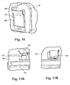
- Figure 10 is a partial perspective view of the bottom-mount freezer refrigerator of Figure 4 illustrating the inside of the refrigerator compartment door and the connection of the ice lifter apparatus to the ice dispenser on the refrigerator compartment door.
- Figure 11A is a partial perspective view of the bottom-mount freezer refrigerator of Figure 8 illustrating the ice lifter apparatus passage through the compartment separator with the closure open.
- Figure 11B is a partial perspective view of the bottom-mount freezer refrigerator of Figure 8 illustrating the ice lifter apparatus passage through the compartment separator with the closure in the closed position.
- Figure 12A is a first perspective view of a conveyor belt lifting apparatus for lifting ice cubes from a freezer-mounted ice cube forming apparatus to a refrigerator-mounted dispenser.
- Figure 12B is a second perspective view of the lifting apparatus illustrated in Figure 12A.
- Figure 12C is a sectional view taken along line 12C-12C of Figure 12A.
- Figure 12D is a sectional view taken along line 12D-12D of Figure 12B.
- Figure 12E is a perspective view of a portion of the conveyor belt illustrated in Figure 12D illustrating a horizontal ice cube remover for removing ice cubes from the conveyor belt.
- Figure 12F is a perspective view of a portion of the conveyor belt illustrated in Figure 12D illustrating a first embodiment of a vertical ice cube remover for removing ice cubes from the conveyor belt.
- Figure 12G is a sectional view taken along line 12G-12G of the portion of the conveyor belt illustrated in Figure 12F.
- Figure 12H is an enlarged perspective view of a second embodiment of a vertical ice cube remover for removing ice cubes from the conveyor belt.
- Figure 12I is a sectional view similar to Figure 12D illustrating an alternate dispensing arrangement.
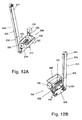
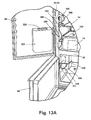
- Figure 13A is a partial perspective view of a bottom-mount refrigerator illustrating an elevator lifting apparatus for lifting ice cubes from a freezer-mounted ice cube forming apparatus to a refrigerator-mounted dispenser.
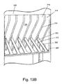
- Figure 13B is an enlarged view of an ice cube remover for removing ice cubes from the elevator lifting apparatus.
- Figure 14A is a first perspective view of an auger lifting apparatus for lifting ice cubes from a freezer-mounted ice cube forming apparatus to a refrigerator-mounted dispenser.
- Figure 14B is a second perspective view of the lifting apparatus illustrated in Figure 14A.
- Figure 14C is an enlarged perspective view of a portion of the lifting apparatus illustrated in Figure 14A illustrating a vertical auger in cooperative register with a horizontal auger.
- Figure 14D is an enlarged perspective view of a portion of the vertical auger illustrated in Figures 14A-C.
- Figure 14E is a sectional view taken along line 14E-14E of Figure 14A.
- Figure 14F is a plan view of a portion of the lifting apparatus illustrated in Figure 14A illustrating the vertical auger and the horizontal auger with an auger enclosure partially removed for clarity.
- Figure 15 is an illustration of one embodiment of an undercounter ice maker having a countertop ice dispenser and ice cube lifter apparatus according to the invention.
- Figure 16 is a partial perspective view of an embodiment of the undercounter ice maker and countertop ice dispenser of Figure 15 illustrating the countertop ice dispenser, part of the interior of the ice maker and a portion of the ice lifter apparatus.
- Figure 17 is a partial perspective view of the undercounter ice maker and countertop ice dispenser of Figure 16 illustrating the ice cube storage bin and dispenser and a portion of the ice lifter apparatus.
- Figure 18 is a partial perspective view of the undercounter ice maker and countertop ice dispenser of Figure 16 illustrating the ice dispensing and ice lifter apparatus positioned under the countertop.
- Figure 19 is a partial perspective view of the undercounter ice maker of Figure 16 illustrating the ice maker with the door closed.
- the inventive concept described herein relates to an ice dispensing unit for dispensing ice at a height convenient for a user, i.e. the user can retrieve ice while in a standing position, which is located above the ice maker apparatus.
- an ice making and storage unit located in a compartment for forming ice cubes and a lifting apparatus for transporting the ice upwardly to a dispensing unit mounted in a space located above the ice cube forming compartment having an above-freezing temperature.
- a refrigerated compartment such as a refrigerated compartment, freezer compartment, refrigerator and freezer compartment doors, a dispenser outlet mounted in the refrigerator compartment door, an ice maker, an ice cube storage container, and the like.
- a refrigerated compartment such as a refrigerated compartment, freezer compartment, refrigerator and freezer compartment doors, a dispenser outlet mounted in the refrigerator compartment door, an ice maker, an ice cube storage container, and the like.
- elements common to more than one embodiment will be identified with common numerals.
- Ice cubes are illustrated in the Figures as generally semicircular pieces of ice, although the inventive concepts described herein are not so limited, and are equally applicable to ice particles having a cylindrical, rectilinear, or other shape.
- the term refrigerator is generally used to refer to an appliance with having both a refrigerated compartment and freezer compartment. However, it can apply to an appliance with only a refrigerated compartment or with only a freezer compartment.
- the ice lifting apparatus embodiments according to the invention can be used with an undercounter ice maker or undercounter freezer to supply ice cubes to an ice dispenser outlet positioned on the counter top adjacent the ice maker.
- operation of elements of the ice lifter apparatus used with an undercounter ice maker will be generally the same as when used in conjunction with a bottom-freezer refrigerator, and a description of their operation will not be repeated, unless otherwise noted.
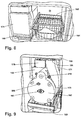
- FIGS 1 and 2 illustrate a bottom-mount refrigerator 50 comprising an embodiment of an ice-making and dispensing apparatus according to the invention.
- the refrigerator 50 comprises a generally well-known insulated cabinet 52 defining an upper refrigerator compartment 54 arranged to operate at above 0°C temperatures and a lower freezer compartment 56 arranged to operate at below 0°C temperatures and located beneath the refrigerator compartment 54.
- the cabinet 52 comprises a pair of insulated sidewalls 58, 60, an insulated top wall 62, and an insulated back wall 64.
- a compartment separator 65 bisects the interior of the cabinet 52 and separates the refrigerator compartment 54 from the freezer compartment 56.
- An insulated freezer compartment door 66 can be hingedly mounted to the cabinet 52 to provide selective access to the freezer compartment 56.
- an insulated refrigerator compartment door 68 can be hingedly mounted to the cabinet 52 to provide selective access to the refrigerator compartment 54. While the freezer compartment door 66 is illustrated as being hingedly mounted about a vertical axis, it could also be configured as a horizontally translating pullout freezer drawer.
- the refrigerator 50 also comprises shelves 74 and storage bins 76, which are illustrated in Figure 2 in the refrigerated compartment 54, but which can also be located in the freezer compartment 56.
- the refrigerator 50 also comprises a traditional cooling system comprising a motor driven compressor and evaporator containing a suitable coolant, one or more ventilation fans, appropriate thermostatic controls for maintaining the refrigerator compartment 54 and the freezer compartment 56 at selected temperatures, and other well-known functional features (not shown), which are not germane to the inventive concepts and will not be further described herein, except as necessary for a complete understanding of the inventive concepts.
- An ice and water dispenser 72 including an ice dispenser outlet, not shown, can be installed in refrigerator compartment door 68 for delivering ice and water through the refrigerated compartment door 68.
- the dispenser 72 can be similar in many respects to an ice and water dispenser disclosed in U.S. Patent No. 6,082,130 to Pastryk et al which is incorporated herein in its entirety.
- Dispenser 72 can also be similar to water and ice dispensers disclosed in U.S. Patent 4,084,725 to Buchser, U.S. Patent 4,176,527 to Linstromberg et al, and U.S. Patent 4,942,979 to Linstromberg et al which are each incorporated herein in their entirety.
- the dispenser 72 can be arranged to deliver whole ice cubes, or can be arranged to selectively deliver whole or crushed ice cubes and/or water in response to activation of a selection control device (not shown) incorporated into the dispenser 72.
- a selection control device not shown
- through-the-door dispensers include one or two actuators (see Figure 4) for activating ice cube or chilled water dispensing by pressing a glass or suitable container against the actuator.
- Dispenser 72 can also include a user interface, not shown, that can include suitable controls for the ice and water dispenser and, if desired, other refrigerator functions.
- the ice and water dispenser controls can be similar to the ice and water dispenser controls disclosed in co-pending U.S. Patent Application S.N. 10/861,203, which is incorporated herein in its entirety.
- FIG. 2 illustrates an embodiment of an ice making and dispensing apparatus 140 comprising an ice maker and storage container module 142 mounted in the freezer compartment 56.
- Ice making and dispensing apparatus 140 can include a lifting mechanism 144 for lifting ice cubes from the freezer compartment 56 to a dispenser module 86 in operable communication with a dispenser 72 that can be positioned on refrigerator compartment door 68 as described above or on a countertop.
- a dispenser module 86 in operable communication with a dispenser 72 that can be positioned on refrigerator compartment door 68 as described above or on a countertop.
- an ice cube storage bin (not shown) can be included in module 86 and can be provided with an ice crushing feature as described in the Pastryk et al patent as described above.
- the dispenser 72 can be arranged to deliver whole ice cubes, or can be arranged to selectively deliver whole or crushed ice cubes and/or water in response to activation of a selection control device (not shown) incorporated into the dispenser 72.
- a selection control device not shown
- suitable cooling arrangements can be included to maintain the ice cube storage bin below 0°C. Examples of a cooling arrangement for an ice storage bin on a refrigerator compartment door are described in co-pending U.S. Patent Application US20040111 filed by Anselmino et al concurrently with this application, which application is entirely incorporated by reference in this application.
- Dispenser module 86 can be provided with an insulated enclosure 96 to facilitate maintaining a below 0°C.
- Ice maker and storage module 142 can form an ice maker compartment in freezer compartment 56. Those skilled in the art will understand that the entire freezer compartment 56 can comprise the ice maker compartment and that the compartment housing the ice maker and ice cube storage bin can be eliminated if desired.
- the ice maker and storage container module 142 is generally similar to a conventional freezer compartment ice making and storage device.
- An ice cube lifter 144 can extend from the freezer compartment 56 into the refrigerated compartment 54 to transport ice cubes from the ice maker and storage container 142 to the dispenser 72 on the refrigerator compartment door as hereinafter described.
- the ice cube lifter 144 is illustrated in Figure 2 as comprising an insulated lifter conduit 146 incorporated into or installed to the insulated side wall 60 of the cabinet 52.
- the ice cube lifter conduit 146 can be suitably insulated and sealed to eliminate the flow of chilled air from the ice cube lifter 144 into the refrigerated compartment 54.
- Ice cube lifter 144 can have an outlet 148 for delivering ice cubes to dispenser inlet 98 when refrigerator compartment door 68 is closed.
- the dispenser control not shown, can be arranged to operate only when refrigerator compartment door 68 is closed so that ice cubes delivered from outlet 148 can fall into dispenser inlet 98.
- the ice maker and storage module 142 can include a suitable mover (not shown) in the ice storage container to move ice cubes toward the ice cube lifter 144, or the ice cube storage container can be arranged to allow gravity feed of ice cubes to the ice cube lifter.
- a water dispenser (not shown) can be integrated into the dispenser 72 so that, in addition to ice cubes, water, or a combination of both ice cubes and water can be selectively provided to a user.
- Suitable flexible connectors for water lines leading from a water valve 95 in the machinery compartment to the ice and water dispenser 72 can be provided to accommodate the movement of the door 68 between the open and closed positions.
- FIG. 3 an alternate embodiment of a bottom-mount freezer refrigerator 50 is illustrated, which is similar to many respects to the embodiment illustrated in Figures 1 and 2.
- a pair of refrigerator compartment doors 102 and 104 can be provided instead of a single door 68.
- An ice maker 140 can be mounted in the freezer compartment 56 as in the embodiment of Figures 1 and 2.
- Shelves 74 and one or more bins 76 can be provide in the refrigerator and / of the freezer compartment as is well-known in the art.
- An ice cube lifter 144' can be provided along and / or wholly or partially imbedded in side wall 60 as described above.
- ice dispenser 72 can have a dispenser inlet 106 extending upward above dispenser 72 on the inside of refrigerator compartment door 102 to connect with ice cube lifter 144'.
- Dispenser inlet 106 can connect and seal to ice cube lifter 144' when refrigerator compartment door 102 is closed.
- suitable seals can be provided to facilitate sealing the outlet, not shown, of ice cube lifter 144' to dispenser inlet 106.
- Freezer compartment 56 can have an ice cube maker 246 positioned above an ice cube storage bin 248.
- a wall 241 can be provided to separate ice maker 246 and ice cube storage bin 248 from the remainder of freezer compartment 56 and can form ice maker compartment 243.
- a vertical belt ice cube lifter 240 can be seen positioned adjacent ice maker compartment 243 along the side wall of freezer compartment 56 extending through compartment separator 65 into refrigerator compartment 54.
- Vertical belt ice cube lifter 240 can include an outlet 292 ( Figure 12A and 12G) and an ice cube lifter outlet chute 232 positioned along side wall 60 of the refrigerator compartment 54.
- Outlet chute 232 can include an outlet chute inlet 233 that can be positioned adjacent outlet 292 so that ice cubes exiting vertical ice cube lifter 240 can fall into outlet chute 232.
- Outlet chute 232 can include an outlet 234 at the end of outlet chute slide 235. Ice cubes falling into outlet chute 232 can freely fall onto outlet slide 235 and slide toward outlet 234.
- Dispenser module 86' can be positioned on refrigerator compartment door 68 and can include dispenser inlet chute 236 that can be secured to the top of dispenser module 86' overlying the dispenser inlet, not shown.
- Dispenser module 86' can be in operable communication with dispenser 72 described above.
- Inlet chute 236 can include an inlet 237 and an inlet chute slide 238 leading down to the dispenser inlet.
- outlet chute outlet 234 and inlet chute inlet 237 can be arranged to form a substantially closed chute leading from vertical belt ice cube lifter 240 to dispenser 86' inlet, not shown, when refrigerator compartment door 68 is closed. Operation of vertical belt ice cube lifter 240 is described in greater detail below in connection with the description of Figures 12A to 12 I.
- Bottom-mount freezer refrigerator 50 can have a refrigerator compartment door 168 that can have an ice and water dispenser 172 positioned on the door generally similar to dispenser 72 described above, and that can include a dispenser outlet, not shown.
- Bottom freezer refrigerator 50 can also have a freezer compartment door 166.
- Ice and water dispenser 172 can include an ice dispenser paddle 200 and a water dispenser paddle 206. When ice dispenser paddle 200 and water dispenser paddle 206 are operated by a user such as by pressing a glass against the desired paddle, the ice and water dispenser control (not shown) can cause dispensing of ice cubes or water as is well known in the art.
- an ice making and dispensing apparatus 174 can be positioned in freezer compartment 56 having a portion extending up into refrigerator compartment 54.
- Freezer compartment 56 can include a shelf 162 and a basket 164.
- An additional storage basket 160 can be slideably mounted under ice making and dispensing apparatus 174 for storage of frozen juice cans and the like.
- shelves 74 and bins 76 described above can be used in refrigerator compartment 54 and freezer compartment 56 if desired.
- Ice making and dispensing apparatus 174 can include an ice maker 176 and an accelerator 173 for propelling ice cubes from an ice cube storage bin 178 to dispenser 172.
- Accelerator 173 can include an accelerator wheel housing 175 that can be a volute, enclosing an accelerator wheel 186.
- Ice making and dispensing apparatus 174 can comprise an ice making compartment including an ice maker 176 and ice cube storage bin 178.
- Accelerator wheel housing 175 can transition into a generally upwardly directed conduit 171 that can have an outlet 191 adjacent compartment separator 165.
- a passage 167 can be provided in compartment separator 165 to provide a passage between the freezer compartment 56 and refrigerator compartment 54 that can connect conduit 171 with an upper conduit 188.
- passage 167 can have a passage door 169 that can be pivotally mounted to compartment separator 165.
- Passage door 169 can be arranged to selectively open and close accelerator passage 167 as shown in Figures 11A and 11B.
- Passage door 169 can be arranged to be spring loaded to allow door 169 to close as shown in Figure 11B when refrigerator compartment door 168 is open and to open as shown in Figure 11A when refrigerator compartment door 168 is closed.
- passage door 169 can be arranged to be operated by refrigerator compartment door 168 or by other operating elements including a solenoid or a wax motor, both not shown.
- passage door 169 can be arranged to be opened by operation of the ice dispenser paddle 200 when the dispenser is activated to limit the amount of time passage door 169 is open to allow below 0°C air from freezer compartment 56 to migrate into refrigerator compartment 54.
- Upper conduit 188 can be arranged on the inside of refrigerator compartment door 168.
- Dispenser 172 can include a dispenser outlet 198 and can be generally similar to dispenser 72 described above.
- Upper conduit 188 can lead from accelerator passage 167 in the compartment separator 165 to dispenser 172 and dispenser inlet 163 as can be seen in Figures 9A, 9B and 10.
- Upper conduit 188 can include an inlet 201 adjacent compartment separator 165 and can be positioned in line with accelerator passage 167 and accelerator conduit 171 when refrigerator compartment door 168 is closed.
- Upper conduit 188 can also include a conduit outlet 190 adjacent dispenser inlet 163.
- accelerator housing 175, conduit 171, compartment separator passage 167 and upper conduit 188 can form a substantially continuous passageway from accelerator wheel 186 to dispenser inlet 163 for ice cubes propelled by accelerator wheel 186.
- dispenser 172 can be any well known ice or ice and water dispenser as used on side by side refrigerator freezers or as described in U.S. Patents 4,084,725 to Buchser, 4,176,527 to Linstromberg et al, 4,942,979 to Linstromberg et al and 6,082,130 to Pastryk et al identified and incorporated by reference above. Ice and water dispenser 172 can have an ice cube dispenser outlet 198 and an ice dispenser paddle or actuator 200.
- Ice dispenser paddle 200 can be arranged to open an ice dispenser door 202 that can be arranged to close the ice cube passage to substantially prevent the escape of refrigerated air except when dispensing ice cubes as is well known in the art.
- through-the-door dispensers typically include a water dispenser that can include a water dispenser outlet, not shown, and a water dispenser paddle 206 to activate the water dispensing apparatus.
- accelerator 173 can include accelerator housing 175 that can be mounted at the front of ice cube storage bin 178.
- Accelerator housing 175 can include a central opening 183 that can be aligned with ice cube bin outlet 184 that can be positioned in the front wall of the ice cube storage bin 178.
- Ice cube storage bin 178 can include a mover for moving ice cubes in the ice cube storage bin 178 forward.
- the mover can be an auger 180 that can be rotatably mounted in ice cube storage bin 178 and arranged to move ice cubes forward in the ice cube storage bin 178 when auger 180 is operated.
- Auger 180 and be operatively connected to an auger motor 182.
- auger 180 When auger motor 182 is activated by pressing on the ice dispenser paddle 200, auger 180 rotates moving ice cubes forward in ice cube storage bin 178 and out through ice cube bin outlet 184. Ice cubes exiting ice cube bin outlet 184 can fall into accelerator 186 to be propelled by accelerator 186 out of accelerator housing 175 through conduit 171, passage 167 in compartment separator 165 and upper conduit 188 and into dispenser 172.
- Accelerator wheel 186 can be rotatably mounted in accelerator housing 175 and can be arranged to be driven by accelerator motor 196 via accelerator motor pulley 197, idler pulley 204, accelerator wheel drive belt 195 and accelerator drive pulley 194.
- An accelerator cover 192 can be provided to close accelerator housing 175.
- Accelerator cover 192 can support accelerator wheel bearing 193, idler pulley bearing 208 and accelerator motor bearing 210.
- Accelerator wheel bearing 193 can rotatable support accelerator wheel 186 in accelerator housing 175.
- idler pulley bearing 208 can support idler pulley 204 in accelerator housing 175.
- Motor shaft bearing 210 can support the end of the motor shaft (not shown) on which accelerator motor pulley 197 is attached.
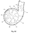
- accelerator wheel 186 can be arranged to be coupled to a motor in other well known operating arrangements. Accelerator wheel 186 can be arranged to rotate at 500 to 3500 rpm to reliably propel ice cubes from accelerator housing 175 to ice dispenser 172. Accelerator motor 196 and auger motor 182 can be arranged to be operably supported adjacent ice cube storage bin 178. Similarly, an ice maker 176 can be positioned above ice cube storage bin 178 and arranged to drop ice cubes harvested from the ice maker into the ice cube storage bin 178 as is well known in the art.
- auger motor 182 can be energized to move ice cubes 185 into the center of accelerator wheel 186.
- Accelerator motor 196 can also be energized to cause accelerator wheel 186 to rotate.
- Blades 187 propel ice cubes 185 rotationally and radially against accelerator wheel housing inner wall 177 with sufficient energy to cause the ice cubes 185 to escape accelerator wheel 186 when there is sufficient space between accelerator wheel 186 and accelerator wheel housing 175 as illustrated in Figure 9C.
- Blades 187 can be positioned generally radially on accelerator wheel 186, or as illustrated in Figure 9C, at an angle from radial in the direction of rotation. Those skilled in the art will understand that the position of blades 187 on accelerator wheel 186 can be determined in order to achieve optimal performance in specific applications depending on parameters that can include system geometry and ice cube configuration among other parameters.
- accelerator wheel housing 175 can take a volute shape around accelerator wheel 186 and define a widening gap between the accelerator wheel 186 and accelerator wheel housing inner wall 177 moving counter clockwise from cutoff 189.
- accelerator conduit 171 can include a bypass, not shown, to direct ice cubes falling back into ice cube storage bin 178.
- ice cube storage bin 178 can be arranged to provide gravity feed of ice cubes stored in the storage bin to the inlet to the accelerator, although, use of a mover such as auger 180 can provide more certain dispensing of ice cubes.
- the ice cube storage bin has been shown positioned in the freezer compartment adjacent the ice maker.
- the ice cube storage bin can be located on the refrigerator compartment door combined with the ice dispenser as generally shown in U. S. Patent 6,082,130 to Pastryk et al fully incorporated herein by reference.
- a supply of below 0°C air or an auxiliary evaporator or other chilling mechanism can be provided to maintain ice cubes in the ice cube storage bin at below 0°C temperatures.
- a vertical conveyor belt lifter 240 comprising a conveyor belt assembly 242 in cooperative register with an ice storage and delivery assembly 244.
- the ice storage and delivery assembly 244 can include a well-known ice maker 246 ( Figure 12C) for forming ice cubes 260, and an ice cube storage bin 248 positioned relative thereto for storing the formed ice cubes 260.
- An ice transfer assembly 250 can be operably connected to the ice cube storage bin 248 and can comprise an auger 252, positioned in ice cube storage bin 248.
- Auger 252 can be driven by an auger motor 256 connected to the auger 252 through a drive belt 258.
- the auger 252 can be adapted to move ice cubes 260 from the ice cube storage bin 248 to an auger bin outlet 262.
- the auger bin outlet 262 can be in communication with a dispenser enclosure 264 that can house a 3-blade dispensing auger 266.
- the dispensing auger 266 can be adapted to manipulate the ice cubes 260 in order to orient each ice cube 260 with a narrow, preferably rectilinear, slot 298 that can extend beneath the dispensing auger 266 and above a dispensing belt 268.
- the slot 298 can be arranged with its longitudinal axis parallel to the axis of the dispensing belt 268 to enable the passage of an ice cube therethrough having its longitudinal axis parallel to the axis of the dispensing belt 268.
- Dispensing auger 266 can be driven by auger motor 256 via drive belt 258, as illustrated in Figure 12B.
- Belt assembly 242 can comprise a dispensing belt 268 enclosed within a belt housing 270, and driven by a belt motor 272. As illustrated in Figures 12D and E, the belt assembly 242 can comprise a generally horizontal section 276 transitioning to a generally vertical section 274.
- the vertical section 274 can be adapted to extend from freezer compartment 56 to refrigerated compartment 54 to deliver ice cubes 260 to an ice and water dispenser 72 or a door-mounted storage container, not shown.
- Horizontal section 276 can be adapted to receive ice cubes 260 from the dispensing auger 266 for transport up the vertical section 274 to the ice and water dispenser 72. Ice and water dispenser 72 can have a dispenser outlet, not shown.
- the dispensing belt 268 can be a flexible, continuous belt approximately the width of an ice cube 260 and comprising a suitable belt material, such as food grade urethane.
- the belt 268 can be provided with a plurality of lifting cleats 278 adapted to extend orthogonally outwardly for supporting ice cubes 260.
- the cleats 278 can be comprised of two or more cleat fingers 280 separated by a stripper space 282.
- the cleats 278 can be spaced along the belt 268 a distance somewhat greater than the length of an ice cube 260, and can have a length somewhat greater than the height of an ice cube 260.
- the belt 268 can be mounted to a plurality of suitably sized and oriented rollers for translation of the belt 268 along the horizontal and vertical directions.
- the belt housing 270 can be somewhat wider than the width of the belt 268 to enable the unrestricted movement of the belt 268 therein.
- the clearance between the belt 268 and the belt housing 270 can be somewhat greater than the height of the lifting cleats 278.
- Each ice cube 260 can move through the belt housing 270 within a compartment defined by the belt 268, a pair of adjoining lifting cleats 278, and the housing 270. Thus, ice cubes 260 can be prevented from falling from the belt 268 or becoming lodged between the belt 268 and the housing 270.
- An upper ice stripper 284 can comprise a plurality of triangular or wedge-shaped plates 288 fixed in a parallel, spaced-apart relationship co-linearly with the longitudinal axis of the belt 268.
- the spacing 290 of the plates 288 can be adapted to the width of the cleat fmgers 280 to enable cleat fingers 280 to pass through the spaces 290 between adjacent plates 288.
- the angular or inclined edge of the plates 288 can be oriented against the movement of the belt 268 so that, when a cleat 278 carrying an ice cube 260 passes through the stripper 284, the plates 288 can strip an ice cube 260 laterally off the cleat 278 ( Figure 12G).
- An upper housing opening 292 can be provided in an upper portion of the vertical section 274 of the belt housing 270 for movement of the ice cubes 260 from the belt 268 to an ice and water dispenser 72.
- ice cubes can be removed through upper housing 292 to an ice and water dispenser 72.
- the upper ice stripper 284 can be oriented to remove ice cubes from the lifting cleats 278 through upper housing opening 292' as the lifting cleats 278 move upwardly through the upper ice stripper 284.
- the choice of selecting a discharge arrangement as illustrated in Figures 12G or 12H can depend on the orientation of upper portion 274 and the arrangement of the inlet to the ice and water dispenser 72.
- a lower stripper 286, similar in operational respects to the upper stripper 284, can be located adjacent the end of the horizontal section 276, as illustrated in Figure 12D.
- the lower stripper 286 can remove ice cubes 260 from the horizontal section 276 when the belt 268 is operated in a reverse direction.
- belt 268 can be operated in a reverse direction to remove ice cubes 260 remaining on conveyor belt 268 in refrigerator compartment 54 when the dispensing operation is completed. Ice cubes 260 removed from belt 268 by lower stripper 286 can accumulate in the space between belt 268 and dispensing auger 266.
- Lower stripper 286 can be movably positioned in belt housing 270 to allow movement out of horizontal section 276 (shown in dashed lines in Figure 12I) and a lower housing opening 294 can be provided in the bottom of the housing enclosing the horizontal section 276 for ice cubes 260 to exit the vertical belt ice lifter 240 to a bulk storage container 296.
- lower stripper 286 can be withdrawn, a closure 295 for lower housing opening 294 can be opened and conveyor belt 268 operated in reverse to dispense ice cubes 260 into a bulk container 296, Figure 12I.
- actuators not shown, under control of a suitable controller, not shown, that can have a Bulk Dispensing option or setting.
- closure 295 can be released when conveyor belt 268 is operated in reverse allowing closure 295 to open, or closure 295 can be resiliently biased closed and the presence of an ice cube 260 on closure 295 can be sufficient to cause closure 295 to open discharging the ice cube, see Figure 121.
- the horizontal section 276 can be eliminated and an ice cube transporting device, such as a well-known auger, a separate conveyor belt, or a gravity-based device, can be used to transfer the ice cubes 260 from the ice maker 246 to the vertical section 274.
- an ice cube transporting device such as a well-known auger, a separate conveyor belt, or a gravity-based device, can be used to transfer the ice cubes 260 from the ice maker 246 to the vertical section 274.
- the belt housing 270 can be insulated and appropriately sealed to prevent the movement of chilled air from the freezer compartment 56 and the vertical belt ice lifter 240 to the refrigerated compartment 54.
- the belt housing 270 can alternately be installed in insulated side wall 60 of the cabinet 52.
- the upper housing opening 292 can cooperatively communicate with an inlet opening (not shown) in the ice and water dispenser 72 or a storage container when the door 68 is closed similar to the embodiment illustrated in Figures 6 and 7.
- An appropriate gasket assembly can seal the opening 292 to the inlet to eliminate the flow of chilled air from the vertical belt ice lifter 240 to the refrigerated compartment 54.
- Ice and water dispenser 72 can include a dispenser outlet as is well known in the art. Also, dispenser 72 could be positioned on a countertop, not shown, and used in conjunction with an undercounter ice maker as described below.
- FIG. 13A and B Another lifting mechanism in the form of an elevating platform ice lifter 300 is illustrated in Figures 13A and B for lifting ice cubes from the freezer compartment 56 to an dispensing module 328 in operable communication with a dispenser 72 that can be positioned on a refrigerator compartment door or on a countertop.
- An ice cube storage bin can be included in module 328 and can be provided with an ice crushing feature as described in the Pastryk et al patent as described above.
- the dispenser 72 can be arranged to deliver whole ice cubes, or can be arranged to selectively deliver whole or crushed ice cubes and/or water in response to activation of a selection control device (not shown) incorporated into the dispenser 72.
- Elevating platform ice lifter 300 will be described in conjunction with a bottom freezer refrigerator, but could be used with an undercounter ice maker as described below.
- the elevating platform ice lifter 300 can comprise an elevating platform assembly 302 comprising a lifting platform 320 which can be incorporated in an elevator housing 326 that can be located adjacent to or in side wall 60.
- the elevator housing 326 can be similar to the conveyor housing in the embodiment of Figures 12A - 12I.
- the embodiment illustrated in Figure 13A elevating platform lifter 300 can comprise a continuous lifting cable 306 traveling around an upper pulley 309 and a lower pulley 311 and can be driven by a drive motor 310.
- the cable 306 can extend along the inside of the elevator housing 326 from the freezer compartment 56 to the refrigerated compartment 54.
- Lifting platform 320 can be attached to the cable 306 in order to raise and lower the lifting platform 320 as the cable 306 travels around the pulleys 309, 311.
- FIG. 13A and B While one lifting platform is shown in the embodiment of Figures 13A and B, those skilled in the art will understand that more than one platform can be provided if desired.
- Ice cubes can be deposited onto the platform 320 from the ice maker 246 using a well-known delivery mechanism, for example by depositing the ice cubes directly from the ice maker onto the platform 320, delivering ice cubes to the platform 320 from a storage container 308 utilizing a conveyor belt or auger, gravity feed of ice cubes from the storage container 308, and the like. Ice cubes can be removed from the platform 320 to an inlet 329 in the module 328 by utilizing a slotted platform and stripper 314, illustrated in Figure 13B, similar to the stripper 284 described with respect to Figures 12F-H.
- the platform 320 can be divided into fingers 322 separated by platform slots 312.
- Stripper 314 can be located adjacent dispensing module inlet 329 and can comprise a plurality of triangular or wedge-shaped plates 316 fixed in a parallel, spaced-apart relationship co-linearly with the longitudinal axis of the elevating platform assembly 302. Stripper 314 can be located partially in opening 327 in elevator housing 326. Each wedge plate can have an inclined face 318.
- the spacing 324 of the plates 316 can be adapted to the width of the platform fingers 322 to enable a platform fingers 322 to pass through the spaces 324 between adjacent plates 316.
- the platform slots 312 can be adapted for the passage of the stripper plates 316 therethrough.
- the angular or inclined edge 318 of the plates 316 can be oriented against the movement of the platform 320 so that, when an ice cube passes through the stripper 314, the plates 316 will urge the ice cube 260 laterally off the platform 320, though opening 327 and into the inlet 329.
- stripper 314 can be eliminated if platform fingers 322 are inclined to allow ice cubes to fall or slide out of opening 327 into inlet 329.
- a chute 304 can be provided to carry ice cubes from opening 327 to dispenser inlet 329.
- Elevating platform ice lifter 300 can be enclosed within a suitable insulated enclosure 326 (illustrated in outlined form in Figure 13A) in the refrigerated compartment 54.
- This can comprise an enclosure 326 that can be mounted to side wall 60 extending into the refrigerated compartment 54 and freezer compartment 56, or the lifter 300 can be installed in side wall 60 within the side wall insulation.
- Suitable flaps or doors can be provided to seal an ice cube discharge outlet 327 from the lifter 300 and the inlet 329 to prevent the flow of chilled air from the lifter 300 into the refrigerated compartment 54.
- chute 304 can be open as illustrated in Figure 13A or, if desired, can be an enclosed chute enclosing opening 327 in elevator housing 326.
- Chute 304 can be enclosed and can be arranged to provide a substantially continuous passage from opening 327 to dispenser inlet 329 when door 68 is closed.
- the substantially continuous passage can be used to convey below 0°C. air from freezer compartment 56 to module 328 if an ice cube storage bin is incorporated in module 328.
- a fan (not shown) can be provided in freezer compartment 56 to move below 0°C. air though lifter 300 to module 328.
- motor 310 can be provided with suitable controls arranged to drive platform 320 from a position adjacent ice maker 246 where ice cubes can be loaded on platform 320 to opening 327 where ice cubes can be stripped off platform 320 into dispenser inlet 329.
- an alternate embodiment of an ice cube lifter is illustrated in Figures 14A-F comprising an auger ice lifter 330.
- the auger ice lifter 330 can comprise a vertical auger assembly 332 and a horizontal auger assembly 334.
- the vertical auger assembly 332 can extend from the freezer compartment 56 into the refrigerated compartment 54 and can be adapted to transport ice cubes from the ice maker 246 to a dispenser 72.
- the vertical auger assembly 332 can comprise an auger 346 adapted for ice cube transport that can be driven by a suitable vertical drive motor 336.
- Auger 346 can be enclosed within a closely-fitting auger housing 342 to provide sufficient clearance between the auger 346 and the housing 342 to enable the auger 346 to rotate within the housing 342 but prevent ice cubes from moving between the auger 346 and the housing 342.
- Horizontal auger assembly 334 can comprise an auger 348 adapted for ice cube transport driven by a horizontal drive motor 338, and can be adapted for ice cube transport from the ice maker 246 to the vertical auger assembly 332.
- Auger 348 can be enclosed within a closely fitting auger housing 344 outside ice cube storage bin 248 to provide sufficient clearance between the auger 348 and the housing 344 to enable the auger 348 to rotate within the housing 344 but prevent ice cubes from moving between the auger 348 and the housing 344.
- housing 344 need not extend into ice cube storage bin 248.
- Horizontal auger 348 can operate openly in ice cube storage bin 248 to move ice cubes toward vertical auger 332.
- Horizontal auger assembly 334 can be replaced with an alternate ice cube transport assembly, for example an open auger as illustrated in U. S. Patent 4,084,725 to Buchser and U.S. Patent 4,942,979 to Lindstromberg et al. incorporated by reference above, a conveyor belt assembly, an inclined chute extending from the ice maker 246 to the vertical auger assembly 332 for gravity feed, and the like.
- the auger ice lifter 330 can be operably connected to an ice storage and delivery assembly similar to that previously described herein, and can comprise an ice maker 246, and an ice cube storage bin 248.
- the lifter 330 can receive ice cubes from the ice cube storage bin 248 and deliver the ice cubes to a dispenser 72.
- ice from the ice cube storage bin 248 can contact horizontal auger 348 that can be positioned in a semi-circular trough in the bottom of ice cube storage bin 248. Operation of the horizontal auger assembly 334 can transport ice cubes toward the vertical auger assembly 332.
- the horizontal auger assembly 334 can be operably connected to the vertical auger assembly 332 so that ice cubes traveling to the end of the horizontal auger assembly 334 are transferred to the vertical auger assembly 332.
- vertical auger assembly 332 can be positioned directly in ice cube storage bin 248.
- the vertical auger assembly 332 can be adapted, such as with an opening in the auger housing 342, to take ice cubes from ice cube storage bin 248 and transport them vertically upwardly to an ice cube dispenser 72.
- Ice dispenser 72 can be part of a bottom freezer refrigerator or an undercounter ice maker and positioned on a countertop adjacent the undercounter ice maker.
- Horizontal auger assembly 334 can be replaced with an alternate ice cube transport assembly, for example a conveyor belt assembly, an inclined chute extending from the ice maker 246 to the vertical auger assembly 332 for gravity feed, and the like.
- Vertical auger housing 344 can comprise a suitably insulated enclosure in the refrigerator compartment 54 to maintain a temperature differential between the auger ice lifter 330 and the refrigerated compartment 54, and to prevent the flow of chilled air to the refrigerated compartment 54.
- the vertical auger assembly 332 can be enclosed within side wall 60 surrounded by insulation, to maintain a sufficiently cold temperature in the vertical auger assembly 332. Flaps or doors cover an ice cube discharge outlet (not shown) from the lifter 330 to prevent the flow of chilled air from the lifter 330 into the refrigerated compartment 54.
- the vertical auger 346 can be reversed after dispensing has been completed to bring ice cubes remaining in the vertical auger assembly 332 back to the freezer compartment 56 by reversing the movement of the vertical auger 346 and the horizontal auger 348 until all ice cubes 260 have been removed from the refrigerated compartment 54.
- Undercounter ice maker 10 can comprise a well-known ice maker such as disclosed in U.S. Patents 4,009,595; 6,484,529 and 6,539,742 fully incorporated herein by reference.
- undercounter ice maker 10 can be an undercounter freezer having an ice maker and storage bin in the freezer compartment.
- Ice maker 10 can include an insulated cabinet 18 defining a ice maker compartment 20 suitable for maintaining a temperature appropriate for forming and storing ice cubes.
- the temperature in the compartment 20 can be maintained in a well-known manner through the use of a cooling system comprising a motor-driven compressor and evaporator containing a suitable coolant, a ventilation fan, appropriate thermostatic controls, and the like.
- the freezer compartment 20 can contain an ice making apparatus 22 adapted for continuously making ice cubes 24. Ice making apparatus 22 can be connected to a suitable water supply (not shown) having appropriate flow controls and a drain (not shown) for draining water not used in ice cube formation or from melting ice cubes as is well known.
- Insulated cabinet 18 can have a side wall 26 that can support ice dispensing apparatus 30 operably connected to ice maker 10 and arranged to elevate ice cubes to dispenser 32 that can be located on countertop 12 for easy access to ice cubes and chilled water.
- Ice maker 10 can have a door 19 that can be pivotally mounted to the front of ice maker 10.
- door 19 can be arranged to pivot on a horizontal axis to the open position illustrated in Figure 17.
- An access panel 21 can be provided below door 19 to afford access to ice maker components under compartment 20.
- a louvered toe plate 25 can be provided at the bottom of ice maker 10 to provide air flow to refrigeration equipment for ice maker 22.
- Door 19 can have a suitable handle 23.
- ice cubes can be accessed in bulk by opening door 19 for direct access to ice cube storage bin 28.
- Ice maker 22 can be arranged to drop the ice cubes 24 into an ice cube storage bin 28 for delivery to a dispenser apparatus 30.
- Ice cube storage bin 28 can incorporate a mover, not shown, that can be similar to auger 180 in ice cube storage bin 178 illustrated in Figure 9B.
- the mover, not shown, in ice cube storage bin 28 can be arranged to advance ice cubes into discharge collar 36 that can be positioned on side wall 26 through suitable openings in compartment 20 and side wall 26.
- discharge collar 36 can include a generally cylindrical wall, not shown, extending through side wall 26 and into ice cube storage bin 28 to form a passage for ice cubes and the auger, not shown.
- ice cube storage bin 28 can be arranged for gravity feed of ice cubes to discharge collar 36 for delivery to curved conduit 38.
- Curved conduit 38 can operatively connect a discharge opening, not shown, in discharge collar 36 with an inlet 42 in accelerator cover 44 for rotating accelerator 40.
- Accelerator 40 can include an accelerator housing 46 enclosing an accelerator wheel, not shown. Accelerator 40 can be similar to and function like the accelerator shown and described in conjunction with Figures 8 to 11.
- a conduit 48 can extend from accelerator housing 46 to dispenser 32 on countertop 12.
- Conduit 48 can have a return curve at its top end like the upper conduit 188 that can extend into dispenser 32 as in the embodiment of Figures 8 to 11.
- Accelerator 40 can be arranged, as previously described with respect to the embodiment illustrated in Figures 8 to 11, to receive ice cubes 24 from the storage container 28, and propel the ice cubes 24 through conduit 48 to dispenser 32.
- Accelerator 40 can include an accelerator wheel, not shown, that can be similar to the accelerator wheel 186 in the embodiment of Figures 8 - 11.
- Accelerator 40 can also include a motor, not shown, that can be integral with accelerator 40, or can be located under compartment 20 in ice maker 10. The operation of accelerator 40 can be similar to accelerator 173 as described above in conjunction with Figures 8 - 11.
- accelerator 40 can be arranged to propel ice cubes 24 with sufficient velocity to carry the ice cubes over the top of conduit 48, not shown, and into dispenser 32.
- a return conduit 49 can extend downwardly from the conduit 48 to a drain pan 47 that can be connected to the ice maker drain, not shown.
- Conduit 48 can extend upwardly and an angle to vertical from the accelerator 40.
- a return conduit 49 can extend downward from a return duct inlet (not shown) on the underside or bottom wall of conduit 48 to drain pan 47.
- Ice cubes falling into drain pan 47 can melt and flow to the undercounter ice maker drain, not shown.
- return conduit 49 can be eliminated and ice cubes not dispensed when accelerator stops can fall back into the accelerator 40 or back into the ice cube storage bin 28.
- Ice dispenser 32 can include a pivotally mounted door (not shown) to close the outlet of conduit 48 when the dispenser is not activated that can be similar to doors for closing the outlet of a through the door ice dispenser are well known in the art.
- a pivotally mounted door (not shown) to close the outlet of conduit 48 when the dispenser is not activated that can be similar to doors for closing the outlet of a through the door ice dispenser are well known in the art.
- One example of such a door can be seen in U.S. Patent 4,942,979 to Lindstromberg et al referred to above.
- a water supply (not shown) can be integrated into the dispenser 32 to selectively provide ice cubes, water, or a combination of both to a user utilizing well-known water delivery devices.
- a tank can be included in compartment 20 to store a quantity of water for the water dispenser.
- the tank can be chilled by the near freezing temperatures normally existing in compartment 20 to facilitate ice cube storage in ice cube bin 28.
- ice cube bin 28 can include a suitable drain connection, not shown, on the bottom wall of bin 28 to carry water from melting ice cubes to drain, not shown. While the ice cube lifter described in conjunction with the undercounter ice maker above is an accelerator lifter, those skilled in the art will understand that any of the embodiments of ice cube lifter according to the invention can be used with an undercounter ice maker as well as a bottom freezer refrigerator.
- the inventive concepts described herein provide the convenience of ice and water dispensing on the refrigerator compartment door of a bottom-mount refrigerator. Since the refrigerated compartment is accessed more frequently than the freezer compartment, the refrigerated compartment occupies the upper portion of the cabinet, improving access to refrigerated items. The less-frequently accessed freezer compartment occupies the lower portion of the cabinet, extending the width of the cabinet. Unlike a side-by-side refrigerator, the full width freezer compartment can accommodate large items.
- the ice making device can be located in the freezer, and the ice cubes can be transported by a transporting mechanism from the freezer compartment to the through-the-door ice cube dispensing device in order to minimize the loss of refrigerated compartment space.
- the ice cube transporting mechanism can be used in conjunction with an undercounter ice maker to supply ice cubes to a dispenser positioned on the countertop.
Landscapes
- Engineering & Computer Science (AREA)
- Physics & Mathematics (AREA)
- Mechanical Engineering (AREA)
- Thermal Sciences (AREA)
- General Engineering & Computer Science (AREA)
- Devices That Are Associated With Refrigeration Equipment (AREA)
Applications Claiming Priority (1)
| Application Number | Priority Date | Filing Date | Title |
|---|---|---|---|
| US10/973,516 US7266951B2 (en) | 2004-10-26 | 2004-10-26 | Ice making and dispensing system |
Publications (3)
| Publication Number | Publication Date |
|---|---|
| EP1653174A2 true EP1653174A2 (de) | 2006-05-03 |
| EP1653174A3 EP1653174A3 (de) | 2015-05-20 |
| EP1653174B1 EP1653174B1 (de) | 2016-08-17 |
Family
ID=35519853
Family Applications (1)
| Application Number | Title | Priority Date | Filing Date |
|---|---|---|---|
| EP05109774.9A Expired - Lifetime EP1653174B1 (de) | 2004-10-26 | 2005-10-20 | Eisherstellung und Abgabesystem |
Country Status (3)
| Country | Link |
|---|---|
| US (7) | US7266951B2 (de) |
| EP (1) | EP1653174B1 (de) |
| AU (1) | AU2005225154A1 (de) |
Cited By (5)
| Publication number | Priority date | Publication date | Assignee | Title |
|---|---|---|---|---|
| WO2008054161A3 (en) * | 2006-11-01 | 2008-08-07 | Lg Electronics Inc | Refrigerator and apparatus for ice discharging therein |
| WO2011092112A1 (de) * | 2010-02-01 | 2011-08-04 | BSH Bosch und Siemens Hausgeräte GmbH | Kältegerät |
| EP2570755A3 (de) * | 2011-09-16 | 2013-12-11 | LG Electronics Inc. | Kühlschrank |
| EP2674702A3 (de) * | 2012-06-12 | 2014-02-26 | LG Electronics, Inc. | Kühlschrank |
| EP4607115A4 (de) * | 2022-12-29 | 2026-01-21 | Hefei Midea Refrigerator Co | Kühlgerät |
Families Citing this family (111)
| Publication number | Priority date | Publication date | Assignee | Title |
|---|---|---|---|---|
| GB2416024B (en) * | 2003-03-28 | 2007-08-29 | Lg Electronics Inc | Refrigerator |
| US7266951B2 (en) * | 2004-10-26 | 2007-09-11 | Whirlpool Corporation | Ice making and dispensing system |
| WO2006083047A1 (en) * | 2005-02-01 | 2006-08-10 | Lg Electronics Inc. | Refrigerator with icemaker |
| US7913509B2 (en) * | 2005-02-01 | 2011-03-29 | Lg Electronics Inc. | Refrigerator |
| US7665316B2 (en) * | 2005-10-25 | 2010-02-23 | Japan Servo Co., Ltd. | Automatic icemaker |
| WO2007139347A1 (en) * | 2006-05-30 | 2007-12-06 | Lg Electronics Inc. | Refrigerator |
| US7614244B2 (en) * | 2006-12-21 | 2009-11-10 | General Electric Company | Ice producing apparatus and method |
| KR100854327B1 (ko) * | 2006-12-29 | 2008-08-26 | 엘지전자 주식회사 | 얼음배출기구, 얼음배출기구가 구비된 냉장고 및얼음배출기구의 제어방법 |
| DE202007013031U1 (de) * | 2007-09-17 | 2007-11-22 | BSH Bosch und Siemens Hausgeräte GmbH | Kältegerät mit Tauwasserkanal |
| CN101903719B (zh) * | 2007-12-14 | 2012-07-04 | Lg电子株式会社 | 用于冰箱的储冰盒 |
| DE202009003232U1 (de) * | 2008-08-29 | 2009-06-04 | BSH Bosch und Siemens Hausgeräte GmbH | Eisspender für ein Kältegerät |
| US9175893B2 (en) * | 2008-11-10 | 2015-11-03 | General Electric Company | Refrigerator |
| US9200828B2 (en) * | 2008-11-10 | 2015-12-01 | General Electric Company | Refrigerator |
| US20100326096A1 (en) * | 2008-11-10 | 2010-12-30 | Brent Alden Junge | Control sytem for bottom freezer refrigerator with ice maker in upper door |
| KR20100092168A (ko) * | 2009-02-12 | 2010-08-20 | 삼성전자주식회사 | 제빙장치 및 이를 포함하는 냉장고 |
| US8997517B2 (en) * | 2009-02-27 | 2015-04-07 | Electrolux Home Products, Inc. | Controlled temperature compartment for refrigerator |
| US8011191B2 (en) | 2009-09-30 | 2011-09-06 | Thermo Fisher Scientific (Asheville) Llc | Refrigeration system having a variable speed compressor |
| US8522566B2 (en) * | 2009-12-14 | 2013-09-03 | Whirlpool Corporation | Mega ice bin |
| KR101659021B1 (ko) * | 2010-02-23 | 2016-09-23 | 엘지전자 주식회사 | 제빙장치 및 이를 구비한 냉장고 |
| US20110226815A1 (en) * | 2010-03-17 | 2011-09-22 | Chin-Wen Chou | Dispensing control device for icemaker |
| DE202010003958U1 (de) | 2010-03-19 | 2010-08-19 | Zippy Technology Corp., Hsin-Tien City | Ausgabe-Steuervorrichtung für Eismaschinen, insbesondere Eiswürfelbereiter |
| US20110252816A1 (en) * | 2010-04-14 | 2011-10-20 | Whirlpool Corporation | Refrigerator icemaker moisture removal and defrost assembly |
| US8863985B2 (en) * | 2010-07-12 | 2014-10-21 | Ice Link, Llc | Method and apparatus for volumetrically supplying ice to ice output systems |
| KR20120010924A (ko) * | 2010-07-27 | 2012-02-06 | 엘지전자 주식회사 | 얼음 이송수단을 갖는 냉장고 |
| KR20120012230A (ko) * | 2010-07-30 | 2012-02-09 | 엘지전자 주식회사 | 아이스 디스펜서를 갖는 냉장고 |
| KR101742586B1 (ko) * | 2010-07-30 | 2017-06-01 | 엘지전자 주식회사 | 급속 제빙기를 갖는 냉장고 |
| KR20120012228A (ko) * | 2010-07-30 | 2012-02-09 | 엘지전자 주식회사 | 복수 개의 아이스 뱅크를 갖는 냉장고 |
| US8464549B2 (en) * | 2010-10-11 | 2013-06-18 | General Electric Company | Airway seal apparatus and method, and refrigerator apparatus using the seal |
| AU2011343814B2 (en) * | 2010-12-17 | 2015-06-18 | Kerry R. Seymour | Ice and chilled water producing and dispensing machine |
| US8556321B2 (en) * | 2011-02-17 | 2013-10-15 | Johnson Truck Bodies, LLC | Refrigerated trailer door having an automotive-style handle and locking mechanism |
| US9127871B2 (en) * | 2011-06-22 | 2015-09-08 | Whirlpool Corporation | Ice making, transferring, storing and dispensing system for a refrigerator |
| KR101913423B1 (ko) * | 2011-09-09 | 2018-12-31 | 엘지전자 주식회사 | 냉장고 |
| US8794023B2 (en) * | 2011-10-31 | 2014-08-05 | General Electric Company | Ice dispenser with crusher for a refrigerator appliance |
| KR101892755B1 (ko) * | 2012-05-16 | 2018-08-28 | 엘지전자 주식회사 | 냉장고 |
| KR101966043B1 (ko) * | 2012-06-12 | 2019-04-05 | 엘지전자 주식회사 | 냉장고 |
| DE102012016501A1 (de) * | 2012-06-29 | 2014-04-24 | Liebherr-Hausgeräte Ochsenhausen GmbH | Kühl- und/oder Gefriergerät |
| KR101929517B1 (ko) * | 2012-06-29 | 2018-12-17 | 엘지전자 주식회사 | 냉장고 |
| US8919146B2 (en) * | 2012-07-03 | 2014-12-30 | Electrolux Home Proucts, Inc. | Soft freeze zone |
| USD727377S1 (en) * | 2013-01-08 | 2015-04-21 | Samsung Electronics Co., Ltd. | Element for refrigerator |
| US9523528B2 (en) * | 2013-01-23 | 2016-12-20 | Whirlpool Corporation | Ice well diverter wedge for ice container |
| US9377233B2 (en) * | 2013-03-14 | 2016-06-28 | Whirlpool Corporation | Ice maker for french door bottom mount refrigerator |
| CN105705889B (zh) * | 2013-10-04 | 2017-11-28 | Lg电子株式会社 | 冰箱 |
| EP3690366B1 (de) * | 2015-08-31 | 2022-06-08 | LG Electronics Inc. | Kühlschrank |
| KR20170069658A (ko) * | 2015-12-11 | 2017-06-21 | 삼성전자주식회사 | 냉장고 |
| US10139145B2 (en) * | 2016-03-30 | 2018-11-27 | Haier Us Appliance Solutions, Inc. | Filters for stand-alone ice making appliances |
| KR102573774B1 (ko) * | 2016-07-13 | 2023-09-04 | 삼성전자주식회사 | 냉장고 |
| WO2018052894A1 (en) | 2016-09-14 | 2018-03-22 | Sears Brands, Llc | Refrigeration device with gesture-controlled dispenser |
| USD842073S1 (en) * | 2016-09-20 | 2019-03-05 | Buster And Punch Limited | Furniture handle |
| CN106907889B (zh) * | 2017-02-13 | 2019-03-15 | 合肥华凌股份有限公司 | 一种冰箱 |
| USD887067S1 (en) | 2017-03-13 | 2020-06-09 | Buster And Punch Limited | Light fixture |
| CN107014127A (zh) * | 2017-05-05 | 2017-08-04 | 青岛海尔股份有限公司 | 一种碎冰器 |
| US10260790B2 (en) * | 2017-06-16 | 2019-04-16 | Haier US Applicance Solutions, Inc. | Refrigerator appliance having an ice storage bin |
| US10712074B2 (en) | 2017-06-30 | 2020-07-14 | Midea Group Co., Ltd. | Refrigerator with tandem evaporators |
| US10837690B2 (en) | 2017-12-08 | 2020-11-17 | Midea Group Co., Ltd. | Refrigerator icemaking system with tandem storage bins and/or removable dispenser recess |
| US11525615B2 (en) | 2017-12-08 | 2022-12-13 | Midea Group Co., Ltd. | Refrigerator icemaking system with tandem storage bins and/or removable dispenser recess |
| KR102490558B1 (ko) | 2018-02-28 | 2023-01-19 | 엘지전자 주식회사 | 냉장고 및 냉장고의 제어 방법 |
| EP4361088A3 (de) * | 2018-06-20 | 2024-05-29 | Whirlpool Corporation | Wasserführung von schrank zu tür eines kühlschranks mit gelenkscharnier |
| EP4336130A1 (de) * | 2018-11-16 | 2024-03-13 | LG Electronics Inc. | Haushaltsgerät mit einem eisbereiter |
| US10852046B2 (en) | 2018-12-10 | 2020-12-01 | Midea Group Co., Ltd. | Refrigerator with door-mounted fluid dispenser |
| CN111829275B (zh) * | 2019-04-17 | 2021-11-12 | 合肥华凌股份有限公司 | 冰块输送装置、制冰机和冰箱 |
| US11293680B2 (en) | 2019-06-14 | 2022-04-05 | Midea Group Co., Ltd. | Refrigerator with multiple ice movers |
| US11053112B2 (en) | 2019-07-08 | 2021-07-06 | Kooler Ice, Inc. | Systems for producing and dispensing chilled water |
| USD1055663S1 (en) | 2019-09-13 | 2024-12-31 | Buster And Punch Limited | Handle |
| USD939927S1 (en) | 2019-09-13 | 2022-01-04 | Buster And Punch Limited | Key blank |
| USD1003071S1 (en) | 2019-09-13 | 2023-10-31 | Buster And Punch Limited | Mounting bracket |
| USD1002232S1 (en) | 2019-09-13 | 2023-10-24 | Buster And Punch Limited | Towel bar |
| WO2021141502A1 (en) * | 2020-01-10 | 2021-07-15 | Van Rooyen Dirk Renier | Ice storage and dispensing apparatus |
| CA197092S (en) | 2020-01-30 | 2022-01-19 | Buster & Punch Ltd | Light fitting |
| USD1022657S1 (en) | 2020-02-06 | 2024-04-16 | Buster And Punch Limited | Door handle |
| CA197546S (en) | 2020-02-07 | 2022-07-22 | Buster & Punch Ltd | Switch plate |
| USD954359S1 (en) | 2020-02-07 | 2022-06-07 | Buster And Punch Limited | Collar |
| KR102902153B1 (ko) * | 2020-02-28 | 2025-12-19 | 삼성전자주식회사 | 냉장고 |
| USD979104S1 (en) | 2020-02-28 | 2023-02-21 | Buster And Punch Limited | Light fitting |
| WO2021243864A1 (en) * | 2020-06-01 | 2021-12-09 | Chun Kit Lai | Ice dispensing system |
| US11326825B2 (en) | 2020-07-16 | 2022-05-10 | Haier Us Appliance Solutions, Inc. | Stand-alone ice and beverage appliance |
| US11402141B1 (en) * | 2020-12-01 | 2022-08-02 | Tracy Polk | Refrigerator and freezer conversion system |
| CN112902518A (zh) * | 2021-01-28 | 2021-06-04 | 深圳市道中创新科技有限公司 | 制冰机的控制方法、装置、计算机设备及存储介质 |
| CA206748S (en) | 2021-03-31 | 2024-01-05 | Buster & Punch Ltd | Tap |
| USD1099669S1 (en) | 2021-05-31 | 2025-10-28 | Buster And Punch Limited | Door hardware |
| CA210523S (en) | 2021-10-01 | 2023-08-21 | Buster & Punch Ltd | Hook for hanging |
| CN117006778A (zh) * | 2022-04-29 | 2023-11-07 | 合肥美的电冰箱有限公司 | 制冷设备及储冰组件 |
| CN118274473B (zh) * | 2022-12-29 | 2025-10-21 | 合肥美的电冰箱有限公司 | 制冷设备的控制方法、制冷设备及存储介质 |
| CN118274538B (zh) * | 2022-12-29 | 2025-08-08 | 合肥美的电冰箱有限公司 | 制冷设备 |
| CN118274474B (zh) * | 2022-12-29 | 2026-04-03 | 合肥美的电冰箱有限公司 | 制冷设备的控制方法、制冷设备及存储介质 |
| CN118274550B (zh) * | 2022-12-29 | 2025-12-19 | 合肥美的电冰箱有限公司 | 制冷设备 |
| CN118274513B (zh) * | 2022-12-29 | 2025-10-21 | 合肥美的电冰箱有限公司 | 移冰装置及制冷设备 |
| CN118274511B (zh) * | 2022-12-29 | 2025-10-21 | 合肥美的电冰箱有限公司 | 移冰装置的控制方法、移冰装置及存储介质 |
| CN118274512B (zh) * | 2022-12-29 | 2026-04-03 | 合肥美的电冰箱有限公司 | 移冰装置的控制方法、移冰装置及存储介质 |
| CN118274541B (zh) * | 2022-12-29 | 2025-08-08 | 合肥美的电冰箱有限公司 | 制冷设备 |
| CN118274510B (zh) * | 2022-12-29 | 2025-12-19 | 合肥美的电冰箱有限公司 | 制冷设备 |
| CN118274548B (zh) * | 2022-12-29 | 2026-04-03 | 合肥美的电冰箱有限公司 | 制冷设备 |
| CN118274514B (zh) * | 2022-12-29 | 2025-10-21 | 合肥美的电冰箱有限公司 | 移冰装置及制冷设备 |
| CN118274516B (zh) * | 2022-12-29 | 2025-08-08 | 合肥美的电冰箱有限公司 | 移冰装置及制冷设备 |
| CN118274507B (zh) * | 2022-12-29 | 2026-04-03 | 合肥美的电冰箱有限公司 | 移冰装置及制冷设备 |
| CN118274547B (zh) * | 2022-12-29 | 2025-08-08 | 合肥美的电冰箱有限公司 | 制冷设备 |
| CN118274515B (zh) * | 2022-12-29 | 2025-12-19 | 合肥美的电冰箱有限公司 | 移冰装置及制冷设备 |
| CN118274542B (zh) * | 2022-12-29 | 2025-12-19 | 合肥美的电冰箱有限公司 | 制冷设备 |
| CN118856761B (zh) * | 2023-04-28 | 2025-08-08 | 合肥华凌股份有限公司 | 门体组件及制冷设备 |
| CN118856765B (zh) * | 2023-04-28 | 2025-08-08 | 合肥华凌股份有限公司 | 制冷设备 |
| CN118856786B (zh) * | 2023-04-28 | 2026-04-03 | 合肥华凌股份有限公司 | 制冷设备的控制方法、制冷设备及存储介质 |
| CN118856691B (zh) * | 2023-04-28 | 2026-04-03 | 合肥华凌股份有限公司 | 移冰装置及制冷设备 |
| CN118856726B (zh) * | 2023-04-28 | 2025-07-18 | 合肥华凌股份有限公司 | 制冷设备 |
| CN118856767B (zh) * | 2023-04-28 | 2025-07-18 | 合肥华凌股份有限公司 | 制冷设备 |
| CN118856760B (zh) * | 2023-04-28 | 2025-10-03 | 合肥华凌股份有限公司 | 门体组件及制冷设备 |
| CN118856763B (zh) * | 2023-04-28 | 2025-07-18 | 合肥华凌股份有限公司 | 制冷设备 |
| CN118856762B (zh) * | 2023-04-28 | 2025-07-18 | 合肥华凌股份有限公司 | 制冷设备 |
| CN118856769B (zh) * | 2023-04-28 | 2025-07-18 | 合肥华凌股份有限公司 | 制冷设备、制冷设备的控制方法及存储介质 |
| CN118856701B (zh) * | 2023-04-28 | 2025-10-21 | 合肥华凌股份有限公司 | 制冰系统的控制方法、装置及存储介质和制冷设备 |
| CN118856759B (zh) * | 2023-04-28 | 2025-08-08 | 合肥华凌股份有限公司 | 门体组件及制冷设备 |
| CN118856766B (zh) * | 2023-04-28 | 2025-12-19 | 合肥华凌股份有限公司 | 制冷设备 |
| CN119309365B (zh) * | 2023-07-11 | 2025-10-21 | 合肥华凌股份有限公司 | 移冰装置及制冷设备 |
Family Cites Families (166)
| Publication number | Priority date | Publication date | Assignee | Title |
|---|---|---|---|---|
| US2199413A (en) * | 1936-03-03 | 1940-05-07 | Caladon Corp | Refrigerating unit |
| US2443926A (en) * | 1944-08-28 | 1948-06-22 | Herbert E Page | Ice cube freezer and dispenser |
| US2692809A (en) * | 1952-02-21 | 1954-10-26 | Gen Motors Corp | Refrigerating apparatus |
| US2712733A (en) | 1954-03-22 | 1955-07-12 | Gen Electric | Freezer compartment in refrigerator door |
| US2900803A (en) * | 1956-12-03 | 1959-08-25 | Jr John F Horton | Ice cube maker and dispenser |
| US3025683A (en) * | 1957-11-08 | 1962-03-20 | Whirlpool Co | Air circulation system and structure |
| US3025679A (en) * | 1961-05-15 | 1962-03-20 | Gen Motors Corp | Refrigeration |
| US3146606A (en) | 1961-09-06 | 1964-09-01 | Whirlpool Co | Apparatus for making clear ice bodies |
| US3146601A (en) | 1963-02-04 | 1964-09-01 | Gen Motors Corp | Refrigerating apparatus |
| US3211338A (en) * | 1963-09-11 | 1965-10-12 | Remcor Prod Co | Ice handling apparatus |
| US3270519A (en) | 1964-12-01 | 1966-09-06 | Gen Motors Corp | Ice maker with door mounted drive means |
| US3350899A (en) * | 1965-05-12 | 1967-11-07 | Gen Electric | Household refrigerator |
| US3226939A (en) | 1965-07-26 | 1966-01-04 | Gen Electric | Household refrigerator including semi-automatic ice service |
| US3390537A (en) * | 1966-10-20 | 1968-07-02 | Market Forge Co | Ice dispensing apparatus |
| US3433030A (en) * | 1967-06-19 | 1969-03-18 | Gen Motors Corp | Automatic liquid freezer |
| US3463362A (en) * | 1967-12-05 | 1969-08-26 | Howard A Garber | Ice dispensing machine |
| US3429140A (en) | 1968-02-09 | 1969-02-25 | Gen Electric | Household refrigerator including ice and water dispensing means |
| JPS4726464Y1 (de) | 1968-09-12 | 1972-08-15 | ||
| US3580428A (en) * | 1969-03-15 | 1971-05-25 | Howard A Garber | Ice dispensing machine |
| US3561231A (en) | 1969-04-03 | 1971-02-09 | Gen Electric | Combination refrigerator with ice service in fresh compartment door |
| US3545217A (en) * | 1969-04-10 | 1970-12-08 | Whirlpool Co | Sensing arm mechanism for icemaker |
| US3650088A (en) * | 1969-09-23 | 1972-03-21 | Fmc Corp | Sealing method and apparatus |
| US3602007A (en) | 1969-10-16 | 1971-08-31 | Gen Electric | Refrigerator including through-the-door ice service |
| US3715119A (en) * | 1970-05-04 | 1973-02-06 | R Shelley | Automatic ice dispenser |
| US3640088A (en) | 1970-06-03 | 1972-02-08 | Gen Electric | Household refrigerator including exterior ice service |
| JPS4726464U (de) | 1971-04-16 | 1972-11-25 | ||
| US3913343A (en) * | 1971-06-14 | 1975-10-21 | Michael L Rowland | Sanitary ice storage and dispensing apparatus and method |
| US3747363A (en) | 1972-05-30 | 1973-07-24 | Gen Electric | Refrigerator including through-the-door ice service |
| US3798923A (en) * | 1972-07-14 | 1974-03-26 | Amana Refrigeration Inc | Refrigerator with ice dispensing means |
| US3789620A (en) * | 1972-11-27 | 1974-02-05 | Gen Motors Corp | Ice door mechanism |
| US3918266A (en) * | 1972-12-01 | 1975-11-11 | Gindy Distributing Company | Ice weighing machine |
| US3933198A (en) * | 1973-03-16 | 1976-01-20 | Hitachi, Ltd. | Heat transfer device |
| US3877241A (en) * | 1973-05-10 | 1975-04-15 | Whirlpool Co | Air transport system for ice maker |
| JPS5069644A (de) | 1973-10-22 | 1975-06-10 | ||
| JPS5436719B2 (de) | 1974-05-30 | 1979-11-10 | ||
| US3969909A (en) | 1975-01-13 | 1976-07-20 | Barto Robert W | Refrigerator water reservoir assembly for the automatic ice maker and the ice water dispenser |
| US4009595A (en) * | 1976-02-06 | 1977-03-01 | Whirlpool Corporation | Ice maker component mounting means |
| US4084725A (en) * | 1976-08-26 | 1978-04-18 | Whirlpool Corporation | Ice piece dispenser |
| JPS5944550B2 (ja) | 1976-09-29 | 1984-10-30 | 株式会社栗本鉄工所 | 遠心力コンクリ−ト管 |
| US4100761A (en) | 1976-12-10 | 1978-07-18 | Whirlpool Corporation | Movable ice receptacle |
| US4087140A (en) | 1977-04-14 | 1978-05-02 | Whirlpool Corporation | Magnetic latch - movable ice receptacle |
| US4209999A (en) | 1978-06-12 | 1980-07-01 | General Electric Company | Household refrigerator with through-the-door ice service |
| US4176528A (en) * | 1978-07-07 | 1979-12-04 | Whirlpool Corporation | Conveyor belt for ice dispenser |
| US4176527A (en) * | 1978-07-13 | 1979-12-04 | Whirlpool Corporation | Ice crusher for refrigerator |
| US4227383A (en) | 1979-05-04 | 1980-10-14 | General Electric Company | Refrigerator including through-the-door ice service |
| JPS5694462U (de) | 1979-12-19 | 1981-07-27 | ||
| US4306757A (en) | 1980-05-27 | 1981-12-22 | General Electric Company | Refrigerator including through-the-door ice service |
| US4285212A (en) | 1980-06-02 | 1981-08-25 | General Electric Company | Ice dispenser storage assembly |
| US4333588A (en) | 1980-08-08 | 1982-06-08 | General Electric Company | Ice dispenser assembly |
| US4368622A (en) * | 1981-05-14 | 1983-01-18 | General Electric Company | Refrigerator with through-the-door quick-chilling service |
| US4942979A (en) * | 1983-06-02 | 1990-07-24 | Whirlpool Corporation | Ice dispensing apparatus |
| US4543800A (en) | 1984-02-16 | 1985-10-01 | White Consolidated Industries, Inc. | Refrigerator door hinge |
| US4732301A (en) * | 1987-01-27 | 1988-03-22 | Tobias Enterprises, Inc. | Ice dispenser |
| US4970871A (en) * | 1989-06-15 | 1990-11-20 | The Coca-Cola Company | Carbonator refrigeration system |
| JPH0633326B2 (ja) | 1989-12-26 | 1994-05-02 | 日本製紙株式会社 | 塩素化ポリジエンの製造および分離方法 |
| DE4013825A1 (de) * | 1990-04-30 | 1991-10-31 | Gaggenau Werke | Ausgabe- und zerkleinerungsvorrichtung fuer kleineisstuecke |
| US5077985A (en) | 1990-09-21 | 1992-01-07 | Whirlpool Corporation | Ice chute for deep door refrigerator |
| US5105631A (en) * | 1990-12-06 | 1992-04-21 | Hoshizaki Denki Kabushiki Kaisha | Ice lift apparatus |
| US5092137A (en) * | 1991-05-16 | 1992-03-03 | Amana Refrigeration, Inc. | Refrigerator cold air duct apparatus |
| JPH04340079A (ja) | 1991-05-17 | 1992-11-26 | Toshiba Corp | セパレート形冷蔵庫 |
| US5211462A (en) | 1991-06-03 | 1993-05-18 | Sub-Zero Freezer Company, Inc. | Double door refrigerator with ice service through the refrigerator door |
| US5117654A (en) | 1991-06-24 | 1992-06-02 | Whirlpool Corporation | Ice conveyor system for refrigerator |
| US5230448A (en) * | 1991-07-24 | 1993-07-27 | Lancer Corporation | Complete system self-contained drink and ice dispensing |
| US5165255A (en) | 1991-07-29 | 1992-11-24 | Mile High Equipment Company | Intermediate staging ice bin for ice and beverage dispensing machines |
| JPH05133655A (ja) | 1991-11-14 | 1993-05-28 | Toshiba Corp | 冷蔵庫 |
| JPH0611228A (ja) | 1992-06-29 | 1994-01-21 | Hitachi Ltd | 自動製氷機付き冷蔵庫 |
| JPH0633326A (ja) | 1992-07-10 | 1994-02-08 | Japan Le-Wa Kk | 紡績機械の清掃方法と装置 |
| US5272888A (en) | 1993-01-05 | 1993-12-28 | Whirlpool Corporation | Top mount refrigerator with exterior ice service |
| US5273219A (en) | 1993-01-11 | 1993-12-28 | White Consolidated Industries, Inc. | Ice dispenser |
| US5359795A (en) | 1993-03-02 | 1994-11-01 | White Consolidated Industries, Inc. | Refrigerator door construction |
| JPH07190578A (ja) | 1993-12-28 | 1995-07-28 | Sanyo Electric Co Ltd | 製氷機 |
| US5375432A (en) * | 1993-12-30 | 1994-12-27 | Whirlpool Corporation | Icemaker in refrigerator compartment of refrigerator freezer |
| EP0745575B1 (de) | 1995-06-02 | 2000-09-06 | Fuji Photo Film Co., Ltd. | Verfahren zur Herstellung einer Polyphenolverbindung und positiv-arbeitende, Polyphenolverbindung enthaltende, Fotoresistzusammensetzung |
| US5737932A (en) | 1995-10-31 | 1998-04-14 | Samsung Electronics Co., Ltd. | Refrigerator having controller for supplying water from a reservoir to either an ice maker or an outside dispenser |
| US5729997A (en) | 1996-02-29 | 1998-03-24 | General Electric Company | Refrigerator air circulation system |
| ES2148643T3 (es) * | 1996-08-16 | 2000-10-16 | Wessamat Eismaschinen Fabrik G | Dispositivo para la entrega de cantidades dosificadas de cubitos de hielo. |
| KR19980018912U (ko) | 1996-09-30 | 1998-07-06 | 배순훈 | 냉장고의 워터디스펜서 물 공급구조 |
| US5813245A (en) | 1996-10-25 | 1998-09-29 | White Consolidated Industries, Inc. | Pressure relief circuit for refrigerator contained water filter |
| JPH10148437A (ja) | 1996-11-18 | 1998-06-02 | Toshiba Corp | 冷蔵庫 |
| JPH10188125A (ja) | 1996-12-26 | 1998-07-21 | Fuji Electric Co Ltd | カップ式飲料自動販売機の給水回路 |
| US6092374A (en) | 1996-12-28 | 2000-07-25 | Samsung Electronics Co., Ltd. | Refrigerator ice-maker water supply apparatus and method thereof |
| JPH10206004A (ja) | 1997-01-27 | 1998-08-07 | Toshiba Corp | 浄水機構付き冷蔵庫 |
| JP3184775B2 (ja) * | 1997-02-20 | 2001-07-09 | 大宇電子株式會▲社▼ | エアカーテン生成装置を利用したドアからの冷気吐出機能を有する冷蔵庫 |
| US5899083A (en) | 1997-03-12 | 1999-05-04 | Whirlpool Corporation | Multi-compartment refrigeration system |
| KR100239520B1 (ko) | 1997-05-17 | 2000-01-15 | 윤종용 | 냉장고용 얼음 공급 장치 |
| CA2206506C (en) * | 1997-05-29 | 2004-01-13 | Nedo Banicevic | Refrigerator mullion |
| US5787724A (en) | 1997-06-04 | 1998-08-04 | Maytag Corporation | Dispensing assembly for top mount refrigerator |
| KR100232848B1 (ko) | 1997-08-30 | 1999-12-01 | 윤종용 | 냉장고의 급수 조절장치 |
| KR100246399B1 (ko) | 1997-09-23 | 2000-04-01 | 구자홍 | 냉장고용 디스펜서어셈블리 및 그 제어방법 |
| JPH11101538A (ja) | 1997-09-26 | 1999-04-13 | Sanyo Electric Co Ltd | 冷蔵庫 |
| KR100234763B1 (ko) | 1997-10-11 | 1999-12-15 | 구자홍 | 냉장고의 급수제어방법 |
| JP3212954B2 (ja) | 1997-11-07 | 2001-09-25 | 三菱電機株式会社 | 冷蔵庫 |
| KR200209397Y1 (ko) | 1997-11-28 | 2001-01-15 | 이정태 | 팩시밀리의 리본카트리지 유출 방지용 잠금장치 |
| KR19990043740A (ko) | 1997-11-29 | 1999-06-15 | 전주범 | 냉장고의 얼음인출장치 |
| KR19990021540U (ko) | 1997-11-29 | 1999-06-25 | 전주범 | 냉장고 |
| KR200174129Y1 (ko) | 1997-12-29 | 2000-03-02 | 서평원 | 에이티엠 교환기의 이중화 씨피유 보드에서 메모리 복사 시스템 |
| KR100277578B1 (ko) | 1997-12-31 | 2001-01-15 | 윤종용 | 디스펜서를갖는냉장고및그작동제어방법 |
| KR100332757B1 (ko) | 1998-01-15 | 2002-06-20 | 구자홍 | 냉장고용 디스펜서의 취출제어방법 |
| KR19990066209A (ko) | 1998-01-22 | 1999-08-16 | 배길성 | 냉장고 |
| JP3112450B2 (ja) | 1998-03-03 | 2000-11-27 | 三星電子株式会社 | 冷蔵庫のアイスディスペンサー |
| JP3688892B2 (ja) | 1998-06-18 | 2005-08-31 | 株式会社東芝 | 冷凍冷蔵庫 |
| US6085542A (en) * | 1998-06-30 | 2000-07-11 | Maytag Corporation | Refrigerator door storage system |
| US6019447A (en) | 1998-08-25 | 2000-02-01 | Maytag Corporation | Refrigerator with varying width fresh food and freezer compartments |
| JP2000105052A (ja) | 1998-09-30 | 2000-04-11 | Sanyo Electric Co Ltd | 冷蔵庫 |
| JP3545617B2 (ja) | 1998-09-30 | 2004-07-21 | 株式会社東芝 | 冷凍冷蔵庫 |
| KR100276739B1 (ko) | 1998-10-31 | 2001-02-01 | 전주범 | 자동제빙기용 급수장치 |
| JP2000146421A (ja) | 1998-11-11 | 2000-05-26 | Toshiba Corp | 冷蔵庫 |
| US6050097A (en) * | 1998-12-28 | 2000-04-18 | Whirlpool Corporation | Ice making and storage system for a refrigerator |
| US6425259B2 (en) | 1998-12-28 | 2002-07-30 | Whirlpool Corporation | Removable ice bucket for an ice maker |
| US6314745B1 (en) | 1998-12-28 | 2001-11-13 | Whirlpool Corporation | Refrigerator having an ice maker and a control system therefor |
| US6148624A (en) | 1998-12-28 | 2000-11-21 | Whirlpool Corporation | Ice making system for a refrigerator |
| US6286324B1 (en) | 1998-12-28 | 2001-09-11 | Whirlpool Corporation | Ice level sensing system for an ice maker |
| US6082130A (en) * | 1998-12-28 | 2000-07-04 | Whirlpool Corporation | Ice delivery system for a refrigerator |
| KR20000050416A (ko) | 1999-01-08 | 2000-08-05 | 구자홍 | 냉장고의 급수관 결빙방지장치 |
| US6120685A (en) | 1999-02-26 | 2000-09-19 | Maytag Corporation | Water filtering system with replaceable cartridge for a refrigerator |
| US6167711B1 (en) * | 1999-04-16 | 2001-01-02 | Restaurant Technology, Inc. | Sanitized ice transportation system and method |
| JP2000320943A (ja) | 1999-05-11 | 2000-11-24 | Matsushita Refrig Co Ltd | 冷蔵庫 |
| KR100572878B1 (ko) | 1999-06-08 | 2006-04-24 | 주식회사 엘지이아이 | 필터내장형 냉장고의 정수유로 제어방법 |
| KR20010008710A (ko) | 1999-07-02 | 2001-02-05 | 구자홍 | 냉장고의 디스펜서용 댐퍼장치 |
| US6209339B1 (en) * | 1999-07-26 | 2001-04-03 | Lancer Partnership, Ltd. | Modular ice delivery system for a beverage dispenser |
| KR200170259Y1 (ko) | 1999-09-03 | 2000-02-15 | 삼성전자주식회사 | 냉장고의 얼음토출구 개폐장치 |
| US7426838B1 (en) | 1999-10-08 | 2008-09-23 | General Electric Company | Icemaker assembly |
| JP4096495B2 (ja) | 1999-12-03 | 2008-06-04 | 三菱電機株式会社 | 冷蔵庫 |
| US6351958B1 (en) | 2000-01-12 | 2002-03-05 | Whirlpool Corporation | Optic level sensing system for use in a refrigerator |
| US6484529B2 (en) * | 2000-04-19 | 2002-11-26 | Whirlpool Corporation | Cabinet construction for an ice maker or other refrigeration appliance |
| TW507061B (en) | 2000-05-22 | 2002-10-21 | Matsushita Refrigeration Corp | Refrigerator |
| JP2002162139A (ja) | 2000-11-20 | 2002-06-07 | Fujitsu General Ltd | 電気冷蔵庫 |
| KR100356542B1 (ko) | 2000-12-29 | 2002-10-19 | 삼성전자 주식회사 | 냉동실을 구비한 냉장고 |
| US6460367B1 (en) | 2001-04-20 | 2002-10-08 | Emerson Electric Co. | Water delivery system for refrigerator |
| JP2002350021A (ja) | 2001-05-31 | 2002-12-04 | Hitachi Ltd | 冷蔵庫 |
| JP2002372349A (ja) | 2001-06-14 | 2002-12-26 | Sanyo Electric Co Ltd | オーガ式製氷機 |
| US6442954B1 (en) | 2001-07-02 | 2002-09-03 | General Electric Company | Dual hopper icemaking refrigerator |
| JP2003056966A (ja) | 2001-08-20 | 2003-02-26 | Fujitsu General Ltd | 冷蔵庫 |
| JP2003075050A (ja) | 2001-09-05 | 2003-03-12 | Toshiba Corp | 冷蔵庫 |
| US6571567B2 (en) | 2001-09-07 | 2003-06-03 | Lg Electronics Inc. | Ice-making apparatus in refrigerator |
| JP3904866B2 (ja) | 2001-09-14 | 2007-04-11 | 株式会社東芝 | 冷蔵庫 |
| JP4059474B2 (ja) | 2001-10-12 | 2008-03-12 | 株式会社東芝 | 冷蔵庫 |
| TW571066B (en) | 2001-10-12 | 2004-01-11 | Toshiba Corp | Refrigerator |
| KR100412951B1 (ko) | 2001-10-16 | 2003-12-31 | 주식회사 엘지이아이 | 냉장고의 디스펜서 물공급장치 |
| US6438988B1 (en) | 2001-10-30 | 2002-08-27 | Dennis J. Paskey | Kit to increase refrigerator ice product |
| US6745578B2 (en) * | 2002-03-15 | 2004-06-08 | Maytag Corporation | Ice maker bail arm raising apparatus for ice storage bin |
| KR100432752B1 (ko) | 2002-05-31 | 2004-05-24 | 엘지전자 주식회사 | 냉장고 |
| JP3973209B2 (ja) * | 2002-08-29 | 2007-09-12 | 芝浦メカトロニクス株式会社 | 液状物質滴下装置及び方法 |
| KR20040023461A (ko) * | 2002-09-11 | 2004-03-18 | 윤제호 | 모자 |
| US6539742B2 (en) * | 2002-10-02 | 2003-04-01 | Whirlpool Corporation | Ice maker with magnetic water conditioner |
| KR100621700B1 (ko) | 2003-01-21 | 2006-09-07 | 삼성전자주식회사 | 얼음공급장치를 갖춘 냉장고 |
| KR100889821B1 (ko) | 2003-01-27 | 2009-03-20 | 삼성전자주식회사 | 온도조절 챔버를 구비한 냉장고 |
| US6735959B1 (en) | 2003-03-20 | 2004-05-18 | General Electric Company | Thermoelectric icemaker and control |
| GB2416024B (en) * | 2003-03-28 | 2007-08-29 | Lg Electronics Inc | Refrigerator |
| US6810682B1 (en) * | 2003-05-20 | 2004-11-02 | Maytag Corporation | Refrigerator with internal water dispenser |
| US6964177B2 (en) | 2003-05-28 | 2005-11-15 | Lg Electronics Inc. | Refrigerator with icemaker |
| KR100565622B1 (ko) | 2003-09-19 | 2006-03-30 | 엘지전자 주식회사 | 냉장고 |
| KR100565621B1 (ko) | 2003-09-19 | 2006-03-29 | 엘지전자 주식회사 | 냉장고 |
| US6952935B2 (en) * | 2003-11-18 | 2005-10-11 | Follett Corporation | Ice making and delivery system |
| EP1580504B1 (de) * | 2004-03-24 | 2017-03-29 | LG Electronics, Inc. | Kaltluftführungsstruktur für eine Eiserzeugungskammer in einer Kaltkammertür |
| KR100621236B1 (ko) * | 2004-05-17 | 2006-09-14 | 엘지전자 주식회사 | 냉장실 도어 제빙실의 그릴 개폐장치 |
| KR100671567B1 (ko) * | 2004-05-18 | 2007-01-18 | 엘지전자 주식회사 | 냉장고용 제빙기의 만빙 감지 장치 |
| US7201005B2 (en) | 2004-06-04 | 2007-04-10 | Whirlpool Corporation | Measured fill water dispenser for refrigerator freezer |
| US7210601B2 (en) | 2004-06-04 | 2007-05-01 | Whirlpool Corporation | Variable flow water dispenser for refrigerator freezers |
| US7065975B1 (en) * | 2004-07-06 | 2006-06-27 | Iowa State University Research Foundation, Inc. | Ice dispenser for refrigerator with bottom mount freezer |
| CA2521359A1 (en) | 2004-09-27 | 2006-03-27 | Maytag Corporation | Apparatus and method for dispensing ice from a bottom mount refrigerator |
| US7266951B2 (en) * | 2004-10-26 | 2007-09-11 | Whirlpool Corporation | Ice making and dispensing system |
| US7266972B2 (en) | 2004-10-26 | 2007-09-11 | Whirlpool Corporation | Ice making and dispensing system |
| US7185508B2 (en) | 2004-10-26 | 2007-03-06 | Whirlpool Corporation | Refrigerator with compact icemaker |
| US7188479B2 (en) | 2004-10-26 | 2007-03-13 | Whirlpool Corporation | Ice and water dispenser on refrigerator compartment door |
| US7437885B2 (en) | 2004-10-26 | 2008-10-21 | Whirlpool Corporation | Water spillage management for in the door ice maker |
-
2004
- 2004-10-26 US US10/973,516 patent/US7266951B2/en not_active Expired - Lifetime
-
2005
- 2005-10-20 EP EP05109774.9A patent/EP1653174B1/de not_active Expired - Lifetime
- 2005-10-25 AU AU2005225154A patent/AU2005225154A1/en not_active Abandoned
-
2007
- 2007-07-30 US US11/830,162 patent/US7509818B2/en not_active Expired - Fee Related
-
2009
- 2009-02-18 US US12/388,096 patent/US7895859B2/en not_active Expired - Fee Related
-
2011
- 2011-01-06 US US12/985,451 patent/US8627679B2/en not_active Expired - Fee Related
-
2012
- 2012-09-10 US US13/608,511 patent/US8720221B2/en not_active Expired - Lifetime
-
2014
- 2014-03-20 US US14/220,483 patent/US20140202197A1/en not_active Abandoned
-
2015
- 2015-08-03 US US14/816,241 patent/US9683771B2/en not_active Expired - Fee Related
Cited By (10)
| Publication number | Priority date | Publication date | Assignee | Title |
|---|---|---|---|---|
| WO2008054161A3 (en) * | 2006-11-01 | 2008-08-07 | Lg Electronics Inc | Refrigerator and apparatus for ice discharging therein |
| WO2011092112A1 (de) * | 2010-02-01 | 2011-08-04 | BSH Bosch und Siemens Hausgeräte GmbH | Kältegerät |
| CN102741629A (zh) * | 2010-02-01 | 2012-10-17 | Bsh博世和西门子家用电器有限公司 | 制冷器具 |
| US20130055741A1 (en) * | 2010-02-01 | 2013-03-07 | BSH Bosch und Siemens Hausgeräte GmbH | Refrigeration appliance |
| CN102741629B (zh) * | 2010-02-01 | 2015-07-15 | Bsh博世和西门子家用电器有限公司 | 制冷器具 |
| EP2570755A3 (de) * | 2011-09-16 | 2013-12-11 | LG Electronics Inc. | Kühlschrank |
| US8925342B2 (en) | 2011-09-16 | 2015-01-06 | Lg Electronics Inc. | Refrigerator |
| EP2674702A3 (de) * | 2012-06-12 | 2014-02-26 | LG Electronics, Inc. | Kühlschrank |
| US9885510B2 (en) | 2012-06-12 | 2018-02-06 | Lg Electronics Inc. | Refrigerator |
| EP4607115A4 (de) * | 2022-12-29 | 2026-01-21 | Hefei Midea Refrigerator Co | Kühlgerät |
Also Published As
| Publication number | Publication date |
|---|---|
| US20120006047A2 (en) | 2012-01-12 |
| US9683771B2 (en) | 2017-06-20 |
| US8627679B2 (en) | 2014-01-14 |
| US20120324940A1 (en) | 2012-12-27 |
| US8720221B2 (en) | 2014-05-13 |
| US20110094255A1 (en) | 2011-04-28 |
| US7895859B2 (en) | 2011-03-01 |
| EP1653174B1 (de) | 2016-08-17 |
| US7266951B2 (en) | 2007-09-11 |
| US20080016899A1 (en) | 2008-01-24 |
| US20060086127A1 (en) | 2006-04-27 |
| US20140202197A1 (en) | 2014-07-24 |
| US20090145158A1 (en) | 2009-06-11 |
| AU2005225154A1 (en) | 2006-05-11 |
| EP1653174A3 (de) | 2015-05-20 |
| US20150338149A1 (en) | 2015-11-26 |
| US7509818B2 (en) | 2009-03-31 |
Similar Documents
| Publication | Publication Date | Title |
|---|---|---|
| US7266951B2 (en) | Ice making and dispensing system | |
| EP1653175B1 (de) | Eisherstellung und Abgabesystem | |
| EP1653179B1 (de) | Eisherstellungs- und Ausgabe-vorrichtung | |
| US8733123B2 (en) | Apparatus and method for dispensing ice from a bottom mount refrigerator | |
| EP1653176B1 (de) | Eisherstellung und Abgabesystem | |
| EP1657510B1 (de) | Eisherstellung und Abgabesystem | |
| KR20110032635A (ko) | 제빙기 및 제빙기를 갖는 냉장고 |
Legal Events
| Date | Code | Title | Description |
|---|---|---|---|
| PUAI | Public reference made under article 153(3) epc to a published international application that has entered the european phase |
Free format text: ORIGINAL CODE: 0009012 |
|
| AK | Designated contracting states |
Kind code of ref document: A2 Designated state(s): AT BE BG CH CY CZ DE DK EE ES FI FR GB GR HU IE IS IT LI LT LU LV MC NL PL PT RO SE SI SK TR |
|
| AX | Request for extension of the european patent |
Extension state: AL BA HR MK YU |
|
| PUAL | Search report despatched |
Free format text: ORIGINAL CODE: 0009013 |
|
| AK | Designated contracting states |
Kind code of ref document: A3 Designated state(s): AT BE BG CH CY CZ DE DK EE ES FI FR GB GR HU IE IS IT LI LT LU LV MC NL PL PT RO SE SI SK TR |
|
| AX | Request for extension of the european patent |
Extension state: AL BA HR MK YU |
|
| RIC1 | Information provided on ipc code assigned before grant |
Ipc: F25C 5/00 20060101AFI20150415BHEP |
|
| 17P | Request for examination filed |
Effective date: 20151118 |
|
| RBV | Designated contracting states (corrected) |
Designated state(s): AT BE BG CH CY CZ DE DK EE ES FI FR GB GR HU IE IS IT LI LT LU LV MC NL PL PT RO SE SI SK TR |
|
| AKX | Designation fees paid |
Designated state(s): DE FR GB IT |
|
| AXX | Extension fees paid |
Extension state: MK Extension state: HR Extension state: AL Extension state: YU Extension state: BA |
|
| GRAP | Despatch of communication of intention to grant a patent |
Free format text: ORIGINAL CODE: EPIDOSNIGR1 |
|
| INTG | Intention to grant announced |
Effective date: 20160225 |
|
| GRAS | Grant fee paid |
Free format text: ORIGINAL CODE: EPIDOSNIGR3 |
|
| GRAA | (expected) grant |
Free format text: ORIGINAL CODE: 0009210 |
|
| AK | Designated contracting states |
Kind code of ref document: B1 Designated state(s): DE FR GB IT |
|
| REG | Reference to a national code |
Ref country code: GB Ref legal event code: FG4D |
|
| REG | Reference to a national code |
Ref country code: FR Ref legal event code: PLFP Year of fee payment: 12 |
|
| REG | Reference to a national code |
Ref country code: DE Ref legal event code: R096 Ref document number: 602005049981 Country of ref document: DE |
|
| REG | Reference to a national code |
Ref country code: DE Ref legal event code: R097 Ref document number: 602005049981 Country of ref document: DE |
|
| PLBE | No opposition filed within time limit |
Free format text: ORIGINAL CODE: 0009261 |
|
| STAA | Information on the status of an ep patent application or granted ep patent |
Free format text: STATUS: NO OPPOSITION FILED WITHIN TIME LIMIT |
|
| 26N | No opposition filed |
Effective date: 20170518 |
|
| REG | Reference to a national code |
Ref country code: FR Ref legal event code: PLFP Year of fee payment: 13 |
|
| REG | Reference to a national code |
Ref country code: FR Ref legal event code: PLFP Year of fee payment: 14 |
|
| PGFP | Annual fee paid to national office [announced via postgrant information from national office to epo] |
Ref country code: DE Payment date: 20191008 Year of fee payment: 15 |
|
| PGFP | Annual fee paid to national office [announced via postgrant information from national office to epo] |
Ref country code: GB Payment date: 20191018 Year of fee payment: 15 |
|
| PGFP | Annual fee paid to national office [announced via postgrant information from national office to epo] |
Ref country code: FR Payment date: 20200914 Year of fee payment: 16 |
|
| PGFP | Annual fee paid to national office [announced via postgrant information from national office to epo] |
Ref country code: IT Payment date: 20200911 Year of fee payment: 16 |
|
| REG | Reference to a national code |
Ref country code: DE Ref legal event code: R119 Ref document number: 602005049981 Country of ref document: DE |
|
| GBPC | Gb: european patent ceased through non-payment of renewal fee |
Effective date: 20201020 |
|
| PG25 | Lapsed in a contracting state [announced via postgrant information from national office to epo] |
Ref country code: DE Free format text: LAPSE BECAUSE OF NON-PAYMENT OF DUE FEES Effective date: 20210501 |
|
| PG25 | Lapsed in a contracting state [announced via postgrant information from national office to epo] |
Ref country code: GB Free format text: LAPSE BECAUSE OF NON-PAYMENT OF DUE FEES Effective date: 20201020 |
|
| PG25 | Lapsed in a contracting state [announced via postgrant information from national office to epo] |
Ref country code: FR Free format text: LAPSE BECAUSE OF NON-PAYMENT OF DUE FEES Effective date: 20211031 |
|
| PG25 | Lapsed in a contracting state [announced via postgrant information from national office to epo] |
Ref country code: IT Free format text: LAPSE BECAUSE OF NON-PAYMENT OF DUE FEES Effective date: 20211020 |