EP1649592B1 - Motorantriebsvorrichtung, die in der lage ist, die entmagnetisierung eines permanentmagnetmotors zu schätzen - Google Patents
Motorantriebsvorrichtung, die in der lage ist, die entmagnetisierung eines permanentmagnetmotors zu schätzen Download PDFInfo
- Publication number
- EP1649592B1 EP1649592B1 EP04747557A EP04747557A EP1649592B1 EP 1649592 B1 EP1649592 B1 EP 1649592B1 EP 04747557 A EP04747557 A EP 04747557A EP 04747557 A EP04747557 A EP 04747557A EP 1649592 B1 EP1649592 B1 EP 1649592B1
- Authority
- EP
- European Patent Office
- Prior art keywords
- demagnetization
- map
- permanent magnet
- motor
- voltage
- Prior art date
- Legal status (The legal status is an assumption and is not a legal conclusion. Google has not performed a legal analysis and makes no representation as to the accuracy of the status listed.)
- Expired - Lifetime
Links
Images


Classifications
-
- B—PERFORMING OPERATIONS; TRANSPORTING
- B60—VEHICLES IN GENERAL
- B60L—PROPULSION OF ELECTRICALLY-PROPELLED VEHICLES; SUPPLYING ELECTRIC POWER FOR AUXILIARY EQUIPMENT OF ELECTRICALLY-PROPELLED VEHICLES; ELECTRODYNAMIC BRAKE SYSTEMS FOR VEHICLES IN GENERAL; MAGNETIC SUSPENSION OR LEVITATION FOR VEHICLES; MONITORING OPERATING VARIABLES OF ELECTRICALLY-PROPELLED VEHICLES; ELECTRIC SAFETY DEVICES FOR ELECTRICALLY-PROPELLED VEHICLES
- B60L15/00—Methods, circuits, or devices for controlling the traction-motor speed of electrically-propelled vehicles
- B60L15/20—Methods, circuits, or devices for controlling the traction-motor speed of electrically-propelled vehicles for control of the vehicle or its driving motor to achieve a desired performance, e.g. speed, torque, programmed variation of speed
-
- B—PERFORMING OPERATIONS; TRANSPORTING
- B60—VEHICLES IN GENERAL
- B60L—PROPULSION OF ELECTRICALLY-PROPELLED VEHICLES; SUPPLYING ELECTRIC POWER FOR AUXILIARY EQUIPMENT OF ELECTRICALLY-PROPELLED VEHICLES; ELECTRODYNAMIC BRAKE SYSTEMS FOR VEHICLES IN GENERAL; MAGNETIC SUSPENSION OR LEVITATION FOR VEHICLES; MONITORING OPERATING VARIABLES OF ELECTRICALLY-PROPELLED VEHICLES; ELECTRIC SAFETY DEVICES FOR ELECTRICALLY-PROPELLED VEHICLES
- B60L50/00—Electric propulsion with power supplied within the vehicle
- B60L50/50—Electric propulsion with power supplied within the vehicle using propulsion power supplied by batteries or fuel cells
- B60L50/51—Electric propulsion with power supplied within the vehicle using propulsion power supplied by batteries or fuel cells characterised by AC-motors
-
- H—ELECTRICITY
- H02—GENERATION; CONVERSION OR DISTRIBUTION OF ELECTRIC POWER
- H02P—CONTROL OR REGULATION OF ELECTRIC MOTORS, ELECTRIC GENERATORS OR DYNAMO-ELECTRIC CONVERTERS; CONTROLLING TRANSFORMERS, REACTORS OR CHOKE COILS
- H02P6/00—Arrangements for controlling synchronous motors or other dynamo-electric motors using electronic commutation dependent on the rotor position; Electronic commutators therefor
- H02P6/34—Modelling or simulation for control purposes
-
- B—PERFORMING OPERATIONS; TRANSPORTING
- B60—VEHICLES IN GENERAL
- B60L—PROPULSION OF ELECTRICALLY-PROPELLED VEHICLES; SUPPLYING ELECTRIC POWER FOR AUXILIARY EQUIPMENT OF ELECTRICALLY-PROPELLED VEHICLES; ELECTRODYNAMIC BRAKE SYSTEMS FOR VEHICLES IN GENERAL; MAGNETIC SUSPENSION OR LEVITATION FOR VEHICLES; MONITORING OPERATING VARIABLES OF ELECTRICALLY-PROPELLED VEHICLES; ELECTRIC SAFETY DEVICES FOR ELECTRICALLY-PROPELLED VEHICLES
- B60L2210/00—Converter types
- B60L2210/10—DC to DC converters
- B60L2210/14—Boost converters
-
- B—PERFORMING OPERATIONS; TRANSPORTING
- B60—VEHICLES IN GENERAL
- B60L—PROPULSION OF ELECTRICALLY-PROPELLED VEHICLES; SUPPLYING ELECTRIC POWER FOR AUXILIARY EQUIPMENT OF ELECTRICALLY-PROPELLED VEHICLES; ELECTRODYNAMIC BRAKE SYSTEMS FOR VEHICLES IN GENERAL; MAGNETIC SUSPENSION OR LEVITATION FOR VEHICLES; MONITORING OPERATING VARIABLES OF ELECTRICALLY-PROPELLED VEHICLES; ELECTRIC SAFETY DEVICES FOR ELECTRICALLY-PROPELLED VEHICLES
- B60L2240/00—Control parameters of input or output; Target parameters
- B60L2240/40—Drive Train control parameters
- B60L2240/42—Drive Train control parameters related to electric machines
- B60L2240/423—Torque
-
- B—PERFORMING OPERATIONS; TRANSPORTING
- B60—VEHICLES IN GENERAL
- B60L—PROPULSION OF ELECTRICALLY-PROPELLED VEHICLES; SUPPLYING ELECTRIC POWER FOR AUXILIARY EQUIPMENT OF ELECTRICALLY-PROPELLED VEHICLES; ELECTRODYNAMIC BRAKE SYSTEMS FOR VEHICLES IN GENERAL; MAGNETIC SUSPENSION OR LEVITATION FOR VEHICLES; MONITORING OPERATING VARIABLES OF ELECTRICALLY-PROPELLED VEHICLES; ELECTRIC SAFETY DEVICES FOR ELECTRICALLY-PROPELLED VEHICLES
- B60L2240/00—Control parameters of input or output; Target parameters
- B60L2240/40—Drive Train control parameters
- B60L2240/54—Drive Train control parameters related to batteries
- B60L2240/545—Temperature
-
- B—PERFORMING OPERATIONS; TRANSPORTING
- B60—VEHICLES IN GENERAL
- B60L—PROPULSION OF ELECTRICALLY-PROPELLED VEHICLES; SUPPLYING ELECTRIC POWER FOR AUXILIARY EQUIPMENT OF ELECTRICALLY-PROPELLED VEHICLES; ELECTRODYNAMIC BRAKE SYSTEMS FOR VEHICLES IN GENERAL; MAGNETIC SUSPENSION OR LEVITATION FOR VEHICLES; MONITORING OPERATING VARIABLES OF ELECTRICALLY-PROPELLED VEHICLES; ELECTRIC SAFETY DEVICES FOR ELECTRICALLY-PROPELLED VEHICLES
- B60L2240/00—Control parameters of input or output; Target parameters
- B60L2240/40—Drive Train control parameters
- B60L2240/54—Drive Train control parameters related to batteries
- B60L2240/547—Voltage
-
- B—PERFORMING OPERATIONS; TRANSPORTING
- B60—VEHICLES IN GENERAL
- B60L—PROPULSION OF ELECTRICALLY-PROPELLED VEHICLES; SUPPLYING ELECTRIC POWER FOR AUXILIARY EQUIPMENT OF ELECTRICALLY-PROPELLED VEHICLES; ELECTRODYNAMIC BRAKE SYSTEMS FOR VEHICLES IN GENERAL; MAGNETIC SUSPENSION OR LEVITATION FOR VEHICLES; MONITORING OPERATING VARIABLES OF ELECTRICALLY-PROPELLED VEHICLES; ELECTRIC SAFETY DEVICES FOR ELECTRICALLY-PROPELLED VEHICLES
- B60L2240/00—Control parameters of input or output; Target parameters
- B60L2240/40—Drive Train control parameters
- B60L2240/54—Drive Train control parameters related to batteries
- B60L2240/549—Current
-
- Y—GENERAL TAGGING OF NEW TECHNOLOGICAL DEVELOPMENTS; GENERAL TAGGING OF CROSS-SECTIONAL TECHNOLOGIES SPANNING OVER SEVERAL SECTIONS OF THE IPC; TECHNICAL SUBJECTS COVERED BY FORMER USPC CROSS-REFERENCE ART COLLECTIONS [XRACs] AND DIGESTS
- Y02—TECHNOLOGIES OR APPLICATIONS FOR MITIGATION OR ADAPTATION AGAINST CLIMATE CHANGE
- Y02T—CLIMATE CHANGE MITIGATION TECHNOLOGIES RELATED TO TRANSPORTATION
- Y02T10/00—Road transport of goods or passengers
- Y02T10/60—Other road transportation technologies with climate change mitigation effect
- Y02T10/64—Electric machine technologies in electromobility
-
- Y—GENERAL TAGGING OF NEW TECHNOLOGICAL DEVELOPMENTS; GENERAL TAGGING OF CROSS-SECTIONAL TECHNOLOGIES SPANNING OVER SEVERAL SECTIONS OF THE IPC; TECHNICAL SUBJECTS COVERED BY FORMER USPC CROSS-REFERENCE ART COLLECTIONS [XRACs] AND DIGESTS
- Y02—TECHNOLOGIES OR APPLICATIONS FOR MITIGATION OR ADAPTATION AGAINST CLIMATE CHANGE
- Y02T—CLIMATE CHANGE MITIGATION TECHNOLOGIES RELATED TO TRANSPORTATION
- Y02T10/00—Road transport of goods or passengers
- Y02T10/60—Other road transportation technologies with climate change mitigation effect
- Y02T10/70—Energy storage systems for electromobility, e.g. batteries
-
- Y—GENERAL TAGGING OF NEW TECHNOLOGICAL DEVELOPMENTS; GENERAL TAGGING OF CROSS-SECTIONAL TECHNOLOGIES SPANNING OVER SEVERAL SECTIONS OF THE IPC; TECHNICAL SUBJECTS COVERED BY FORMER USPC CROSS-REFERENCE ART COLLECTIONS [XRACs] AND DIGESTS
- Y02—TECHNOLOGIES OR APPLICATIONS FOR MITIGATION OR ADAPTATION AGAINST CLIMATE CHANGE
- Y02T—CLIMATE CHANGE MITIGATION TECHNOLOGIES RELATED TO TRANSPORTATION
- Y02T10/00—Road transport of goods or passengers
- Y02T10/60—Other road transportation technologies with climate change mitigation effect
- Y02T10/72—Electric energy management in electromobility
Definitions
- the present invention relates to a motor drive apparatus capable of estimating demagnetization of a permanent magnet motor.
- Hybrid vehicles have recently been of great interest as environment-friendly vehicles.
- the hybrid vehicles are now partially commercialized.
- a hybrid vehicle has, as its motive power sources, a DC (direct current) power supply, an inverter and a motor driven by the inverter in addition to a conventional engine. More specifically, the engine is driven to secure the motive power source and a DC voltage from the DC power supply is converted by the inverter into an AC voltage to be used for rotating the motor and thereby securing the motive power source as well.
- a DC (direct current) power supply DC (direct current) power supply
- the engine is driven to secure the motive power source and a DC voltage from the DC power supply is converted by the inverter into an AC voltage to be used for rotating the motor and thereby securing the motive power source as well.
- Japanese Patent Laying-Open No. 2001-157304 discloses a motor drive system for a hybrid vehicle.
- the motor drive system estimates demagnetization of a permanent magnet of an electric rotating machine from the temperature of the permanent magnet according to data used for controlling the hybrid vehicle.
- the conventional method estimates demagnetization from the temperature of the permanent magnet which is estimated according to the control data for the hybrid vehicle, resulting in a problem that the demagnetization cannot accurately be estimated.
- document US 5,650,706 discloses a control device for a salient pole type permanent magnet motor. There, a magnetic flux of a magnet is detected by an arithmetic operation or actual measurement, and a demagnetization rate is calculated in accordance with the thus detected magnetic flux. A target of controlling the phase is calculated with reference to a demagnetization rate obtained by the calculation. The phase of a motor current is controlled depending on the target of control obtained by the calculation. Thereby, a torque is prevented from lowering due to demagnetization of the magnet.
- An object of the present invention is thus to provide a motor drive apparatus cable of accurately estimating demagnetization of a permanent magnet motor.
- the motor drive apparatus further includes a converter.
- the converter changes an input voltage necessary for driving the permanent magnet motor.
- the estimation unit corrects the estimated amount of demagnetization according to the level of the input voltage.
- the estimation unit estimates the amount of demagnetization by comparing the voltage control amount of the q axis to be controlled with a reference value.
- the estimation unit estimates the amount of demagnetization based on a difference between a reference value and the voltage control amount of the q axis to be controlled.
- the estimation unit holds, in the form of a map, the reference values correlated with at least two revolution numbers to extract the reference value and estimate the amount of demagnetization.
- the reference value is the voltage control amount of the q axis when no demagnetization of the permanent magnet motor occurs.
- the amount of demagnetization is estimated based on the voltage control amount of the q axis applied when the permanent magnet motor is controlled using the d-q axis transformation, namely the armature flux linkage in the direction of the q axis among armature flux linkages emitted from permanent magnets. Then, if the estimated amount of demagnetization is larger than a predetermined value, the operation of the permanent magnet motor is limited.
- the present invention can in this way estimate the amount of demagnetization accurately and, based on the estimated amount of demagnetization, the permanent magnet motor can appropriately be handled.
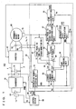
- a motor drive apparatus 100 includes a DC power supply 10, voltage sensors 11 and 12, a converter 20, a capacitor 30, an inverter 40, electric-current sensors 50, a rotational position sensor 70, and control devices 80 and 90.
- Converter 20 is connected between DC power supply 10 and capacitor 30.
- Capacitor 30 is connected between a power supply line 1 and a ground line 2.
- Voltage sensor 11 detects a DC voltage Vb which is output from DC power supply 10 to output the detected voltage to control device 90.
- Voltage sensor 12 detects a terminal-to-terminal voltage Vm of capacitor 30 to output the detected voltage Vm to control devices 80 and 90.
- Converter 20 increases DC voltage Vb from DC power supply 10 in response to signal PWM1 from control device 90 to apply the increased voltage to capacitor 30.
- Capacitor 30 then smoothes the DC voltage from converter 20 to apply the smoothed DC voltage to inverter 40.
- Inverter 40 receives the DC voltage via capacitor 30 to convert the DC voltage into an AC voltage in response to signal PWM2 from control device 80 and thereby drive a permanent magnet motor 60.
- Electric-current sensors 50 detect motor currents Iu and Iv flowing through permanent magnet motor 60 to output the detected motor currents Iu and Iv to control device 80.
- Fig. 1 there are provided only two current sensors 50 for the following reason. It is supposed here that permanent magnet motor 60 is a three-phase motor. Then, motor currents Iu and Iv flowing through two phases respectively may be detected to calculate, from the detected motor currents Iu and Iv, motor current Iw flowing through the remaining phase. Therefore, if these motor currents Iu, Iv and Iw flowing through respective three phases are to be detected separately, three current sensors 50 may be provided.
- Permanent magnet motor 60 which is the three-phase motor includes U, V and W-phase coils as stator coils.
- Rotational position sensor 70 detects a rotational position of a rotor of permanent magnet motor 60 to output a sensor value ⁇ indicative of the detected rotational position to control device 80.
- Control device 80 includes a revolution number detection unit 81, a three-phase to two-phase transformation unit 82, a current command generation unit 83, subtracters 84 and 85, a PI control unit 86, a two-phase to three-phase transformation unit 87, a PWM generation unit 88, a map holding unit 89, and a demagnetized state calculation unit 91.
- Revolution number detection unit 81 receives sensor value ⁇ from rotational position sensor 70 to detect a motor revolution number MRN (number of revolutions of the motor) based on the received sensor value ⁇ . Revolution number detection unit 81 then outputs this motor revolution number MRN to current command generation unit 83, map holding unit 89, demagnetized state calculation unit 91 and control device 90.
- three-phase to two-phase transformation unit 82 performs three-phase to two-phase transformation on motor currents Iu, Iv and Iw using sensor value ⁇ from rotational position sensor 70. Specifically, three-phase to two-phase transformation unit 82 substitutes motor currents Iu, Iv and Iw and sensor value ⁇ into the following expression to calculate current values Id and Iq.
- Id Iq 2 3 ⁇ - cos ⁇ - cos ⁇ - 2 3 ⁇ ⁇ - cos ⁇ + 2 3 ⁇ ⁇ sin ⁇ sin ⁇ - 2 3 ⁇ ⁇ sin ⁇ + 2 3 ⁇ ⁇ ⁇ Iu Iv Iw
- three-phase to two-phase transformation unit 82 transforms respective three-phase motor currents Iu, Iv and Iw flowing through respective three-phase coils of permanent magnet motor 60 into current values Id and Iq.
- Three-phase to two-phase transformation unit 82 then outputs the calculated current values Id and Iq to subtracters 84 and 85 respectively.
- Current command generation unit 83 receives a torque command value TR from an ECU (Electrical Control Unit) provided outside motor drive apparatus 100, receives motor revolution number MRN from revolution number detection unit 81 and receives voltage Vm from voltage sensor 12. Then, current command generation unit 83 generates, based on these torque command value TR, motor revolution number MRN and voltage Vm, current commands Id* and Iq* for outputting the torque indicated by torque command value TR, outputs the generated current command Id* to subtracter 84 and map holding unit 89 and outputs the generated current command Iq* to subtracter 85 and map holding unit 89.
- ECU Electronic Control Unit
- Subtracter 84 calculates deviation ⁇ Id between current command Id* and current value Id to output the calculated deviation ⁇ Id to PI control unit 86.
- Subtracter 85 calculates deviation ⁇ Iq between current command Iq* and current value Iq to output the calculated deviation ⁇ Iq to PI control unit 86.
- PI control unit 86 uses a PI gain for deviations ⁇ Id and ⁇ Iq to calculate voltage control amounts Vd and Vq for adjusting the motor current, outputs the calculated voltage control amount Vd to two-phase to three-phase transformation unit 87 and outputs the calculated voltage control amount Vq to two-phase to three-phase transformation unit 87 and demagnetized state calculation unit 91.
- Two-phase to three-phase transformation unit 87 performs two-phase to three-phase transformation on voltage control amounts Vd and Vq from PI control unit 86 using sensor value ⁇ from rotational position sensor 70. Specifically, two-phase to three-phase transformation unit 87 substitutes voltage control amounts Vd and Vq from PI control unit 86 and sensor value ⁇ from rotational position sensor 70 into the following expression to calculate voltage control amounts Vu, Vv and Vw to be applied to the three-phase coils of permanent magnet motor 60.
- Vu Vv Vw - cos ⁇ sin ⁇ - cos ⁇ - 2 3 ⁇ ⁇ sin ⁇ - 2 3 ⁇ ⁇ - cos ⁇ + 2 3 ⁇ ⁇ sin ⁇ + 2 3 ⁇ ⁇ Id Iq
- two-phase to three-phase transformation unit 87 transforms voltage control amounts Vd and Vq applied to the d axis and the q axis into voltage control amounts Vu, Vv and Vw applied to the three-phase coils of permanent magnet motor 60.
- two-phase to three-phase transformation unit 87 outputs voltage control amounts Vu, Vv and Vw to PWM generation unit 88.
- PWM generation unit 88 generates signal PWM2 based on voltage control amounts Vu, Vv and Vw and voltage Vm from voltage sensor 12 to output the generated signal PWM2 to inverter 40. More specifically, PWM generation unit 88 sets the amplitude and width of a pulse according to the level of voltage Vm to generate signal PWM2. Here, if the level of voltage Vm is relatively higher, PWM generation unit 88 makes the amplitude of the pulse relatively higher while making the width thereof relatively smaller to generate signal PWM2.
- Map holding unit 89 holds a map showing a voltage control amount Vq_map of the q axis measured for each pair of current commands Id* and Iq*, and the control amount is correlated with at least two motor revolution numbers.
- This voltage control amount Vq_map is a voltage control amount of the q axis in a case where permanent magnet motor 60 is not demagnetized.
- Map holding unit 89 receives current commands Id* and Iq* from current command generation unit 83 and receives motor revolution number MRN from revolution number detection unit 81 to extract voltage control amount Vq_map correlated with these motor revolution number MRN and current commands Id* and Iq* and output the extracted control amount to demagnetized state calculation unit 91.
- Demagnetized state calculation unit 91 calculates, according to a method hereinlater described, an amount of demagnetization of permanent magnet motor 60 based on voltage control amount Vq of the q axis from PI control unit 86, voltage control amount Vq_map from map holding unit 89 and motor revolution number MRN from revolution number detection unit 81, and limits the current to be flown to permanent magnet motor 60 or motor revolution number MRN of permanent magnet motor 60 or outputs operation signal OPE for outputting a warning to the outside if the calculated amount of demagnetization is greater than a predetermined value.
- demagnetized state calculation unit 91 corrects, with a method hereinlater described, the calculated amount of demagnetization according to the level of voltage Vm from voltage sensor 12.
- Control device 90 generates signal PWM1 for controlling converter 20 based on torque command value TR from the external ECU, DC voltage Vb from voltage sensor 11, voltage Vm from voltage sensor 12 and motor revolution number MRN from revolution number detection unit 81, and outputs the generated signal PWM1 to converter 20.
- control device 90 calculates a voltage command for converter 20 based on torque command value TR and motor revolution number MRN to generate, based on the calculated voltage command, DC voltage Vb and voltage Vm, signal PWM1 for setting voltage Vm to the voltage command.
- Fig. 2 is a circuit diagram of converter 20 shown in Fig. 1 .
- converter 20 includes NPN transistors Q1 and Q2, diodes D1 and D2 and a reactor L1.
- NPN transistors Q1 and Q2 are connected in series between power-supply line 1 and ground line 2.
- Reactor L1 has one end connected to the intermediate point between NPN transistor Q1 and NPN transistor Q2 and the other end connected to the positive electrode of DC power supply 10.
- diodes D1 and D2 for allowing current to flow from the emitter to the collector of the transistors each are connected respectively.
- Fig. 3 is a circuit diagram of inverter 40 shown in Fig. 1 .
- inverter 40 includes a U phase arm 15, a V phase arm 16 and a W phase arm 17.
- U phase arm 15, V phase arm 16 and W phase arm 17 are provided in parallel between power-supply line 1 and ground line 2.
- U phase arm 15 is comprised of NPN transistors Q3 and Q4 connected in series
- V phase arm 16 is comprised of NPN transistors Q5 and Q6 connected in series
- W phase arm 17 is comprised of NPN transistors Q7 and Q8 connected in series.
- diodes D3-D8 for allowing current to flow from the emitter to the collector of NPN transistors Q3-Q8 each are connected respectively.
- the intermediate point of the phase arms each of inverter 40 is connected to an end of the phase coils each of permanent magnet motor 60.
- the end of the U phase coil of permanent magnet motor 60 is connected to the intermediate point between NPN transistors Q3 and Q4
- the end of the V phase coil thereof is connected to the intermediate point between NPN transistors Q5 and Q6
- the end of the W phase coil thereof is connected to the intermediate point between NPN transistors Q7 and Q8.
- Figs. 4A and 4B conceptually illustrate how to calculate an amount of demagnetization of permanent magnet motor 60 shown in Fig. 1 .
- the voltage generated by magnets of permanent magnet motor 60 appears in the direction of the q axis.
- the amount of demagnetization of permanent magnet motor 60 is calculated based on voltage control amount Vq of the q axis that is applied when permanent magnet motor 60 is controlled using the d-q axis transformation.
- Vq ⁇ - ⁇ LdId + RIq
- ⁇ rotational angular velocity
- ⁇ armature flux linkage by permanent magnets
- Ld inductance of the q axis
- R armature resistance
- Id d axis component of armature current
- Iq q axis component of the armature current
- Equation (3) the term ⁇ LdId is used for field-weakening control.
- Fig. 4A shows a case where no demagnetization occurs while Fig. 4B shows a case where demagnetization occurs.
- the armature flux linkage is ⁇ c and the voltage control amount of the q axis is Vqc. Then, in the case where no demagnetization occurs, the following expression is established.
- Vqc ⁇ c - ⁇ LdId + RIq If demagnetization occurs, the armature flux linkage is ⁇ 1 and the voltage control amount of the q axis is Vq1. Then, in the case where demagnetization occurs, the following expression is established.
- Vq ⁇ 1 ⁇ ⁇ 1 - ⁇ LdId + RIq
- Expression (5) is then subtracted from expression (4):
- voltage control amount Vqc of the q axis in the case where no demagnetization occurs is measured in advance for each pair of current commands Id* and Iq* and the resultant value Vq_map is held in the form of the map. Then, the measured value Vq_map, voltage control amount Vq1 to be controlled and rotational angular velocity ⁇ are substituted into expression (6) to determine the amount of demagnetization ⁇ c - ⁇ 1.
- the amount of demagnetization is calculated based on voltage control amount Vq of the q axis in controlling permanent magnet motor 60 through the d-q axis transformation. Then, from the calculated amount of demagnetization, it is determined whether or not demagnetization of permanent magnet motor 60 occurs.
- Fig. 5 conceptually shows the map held by map holding unit 89 shown in Fig. 1 .
- this map MAP is comprised of a plurality of voltage control amounts Vq_map each located at a point of intersection between a line representing a motor revolution number and a line representing a torque.
- the white circles in Fig. 5 each represent voltage control amount Vq_map.
- This map MAP includes voltage control amounts Vq_map for at least two motor revolution numbers MRN1 and MRN 2.
- the torque is a function between the d axis component Id and the q axis component Iq of the armature current, so that the torque shown in Fig. 5 represents the d axis component Id and the q axis component Iq of the armature current. Therefore, the fact that voltage control amount Vq_map is located at the point of intersection between a line representing a motor revolution number and a line representing a torque means that voltage control amount Vq_map is located at the point of intersection between the line representing the motor revolution number and respective lines representing the d axis component Id and the q axis component Iq of the armature current.
- map MAP is comprised of voltage control amounts Vq_map correlated with motor revolution numbers MRN1, MRN2 and the d axis component Id and the q axis component Iq of the armature current.
- map holding unit 89 receives current commands Id* and Iq* from current command generation unit 83 and receives motor revolution number MRN from revolution number detection unit 81.
- map MAP is comprised of voltage control amounts Vq_map correlated with motor revolution numbers MRN1 and MRN2 and d axis and q axis components Id and Iq of the armature current. Then, map holding unit 89 extract from map MAP voltage control amount Vq_map located at the point correlated with current commands Id* and Iq* from current command generation unit 83 and motor revolution number MRN from revolution number detection unit 81 to output the extracted voltage control amount Vq_map to demagnetized state calculation unit 91.
- Demagnetized state calculation unit 91 receives voltage control amount Vq from PI control unit 86, receives voltage control amount Vq_map from map holding unit 89 and receives motor revolution number MRN from revolution number detection unit 81. Then, demagnetized state calculation unit 91 calculates rotational angular velocity ⁇ based on motor revolution number MRN from revolution number detection unit 81 and substitutes the calculated rotational angular velocity ⁇ and voltage control amounts Vq_map and Vq into expression (6). In this case, voltage control amount Vq_map is substituted for Vqc of expression (6) and voltage control amount Vq is substituted for Vq1 of expression (6).
- demagnetized state calculation unit 91 determines that demagnetization of permanent magnet motor 60 occurs to generate operation signal OPE and output this signal to the external ECU. In contrast, if the result of calculation ⁇ c - ⁇ 1 is equal to or smaller than the predetermined value, demagnetized state calculation unit 91 determines that no demagnetization of permanent magnet motor 60 occurs.
- demagnetized state calculation unit 91 calculates an amount of change in armature flux linkage based on voltage control amount Vq_map which is measured in advance when no demagnetization of permanent magnet motor 60 occurs as well as voltage control amount Vq to be controlled and determines, from the result of the calculation, whether or not demagnetization of permanent magnet motor 60 occurs.
- sensor value ⁇ from rotational position sensor 70 reflects the demagnetization and accordingly, three-phase to two-phase transformation unit 82 transforms motor currents Iu, Iv and Iw into current values Id and Iq with sensor value ⁇ reflecting the demagnetization. Current values Id and Iq are thus influenced by demagnetization.
- Demagnetized state calculation unit 91 corrects, according to the input voltage of inverter 40, namely the level of output voltage Vm of converter 20, the amount of demagnetization ⁇ c - ⁇ 1 which is calculated by the above-described method.
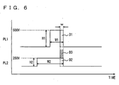
- Fig. 6 is a timing chart of voltage commands of converter 20 shown in Fig. 1 . It is herein described above that voltage control amount Vq_map in the case where no demagnetization of permanent magnet motor 60 occurs is measured in advance.
- the measured voltage control amount Vq_map includes the dead time ofNPN transistors Q3-Q8 that are components of inverter 40.
- the voltage command of the q axis is represented by signal PL1.
- Signal PL1 is a pulse signal with width W1 and height H1. This signal PL1 includes dead time D1. Dead time D1 has the same height H1 as that of signal PL1 and width w.
- the voltage command of the q axis namely voltage control amount Vq_map
- the dead time which should essentially be included in signal PL2 is dead time D2 having height H2 and width w.
- voltage control amount Vq_map being measured at the DC voltage of 500 V
- signal PL2 has the same dead time D1 as that of signal PL1 if no dead time correction is made for addressing the decrease in DC voltage applied to inverter 40.
- signal PL2 includes an extra dead time D3 in addition to dead time D2 which should essentially be included.
- demagnetized state calculation unit 91 corrects voltage control amount Vq_map from map holding unit 89 by expressions (7) and (8) according to the level of voltage Vm from voltage sensor 12.
- Vq_map_ad Vq_map ⁇ Vdead_q
- Vdead_q Vmi - Vmf * Di * fc * cos ⁇ * 3 1 / 2
- Vmi is input voltage to inverter 40 in measuring voltage control amount Vq_map
- Vmf is input voltage to inverter 40 under control
- Di dead time in measuring voltage control amount Vq_map
- fc switching frequency of inverter 40
- ⁇ is angle formed by the q axis and a current vector.
- Demagnetized state calculation unit 91 then substitutes the corrected voltage control amount Vq_map_ad, voltage control amount Vq to be controlled and rotational angular velocity ⁇ into expression (6) to calculate the amount of demagnetization ⁇ c - ⁇ 1.
- the calculation of the amount of demagnetization ⁇ c - ⁇ 1 with the corrected voltage control amount Vq_map_ad corresponds to correction of the amount of demagnetization ⁇ c - ⁇ 1.
- demagnetized state calculation unit 91 corrects the amount of demagnetization ⁇ c - ⁇ 1 according to the level of the input voltage to inverter 40. It is noted that the correction of the dead time according to the input voltage can be made by providing Vq_maps correlated with respective voltages.
- motor drive apparatus 100 includes converter 20 as shown in Fig. 1 , the level of voltage Vm applied to inverter 40 varies depending on the output torque of permanent magnet motor 60.
- the amount of demagnetization is corrected according to the level of the DC voltage applied to inverter 40 in terms of accurate determination of the amount of demagnetization for motor drive apparatus 100 having converter 20.
- voltage control amount Vq_map may also be corrected if the switching frequency of inverter 40 under control changes from the switching frequency of inverter 40 at the time when voltage control amount Vq_map is measured.
- demagnetized state calculation unit 91 calculates the difference between voltage control amount Vq_map of the q axis in the case where no magnetization of permanent magnet motor 60 occurs and voltage control amount Vq to be controlled that is calculated by PI control unit 86 to estimate the amount of demagnetization ⁇ c - ⁇ 1.
- voltage control amount Vq to be controlled may be compared with voltage control amount Vq_map (corresponding to "reference value") to determine whether or not demagnetization of permanent magnet motor 60 occurs according to the result of the comparison.
- demagnetized state calculation unit 91 determines that demagnetization of permanent magnet motor 60 occurs if voltage control amount Vq is smaller than voltage control amount Vq_map and determines that no demagnetization of permanent magnet motor 60 occurs if voltage control amount Vq is equal to voltage control amount Vq_map.
- Motor drive apparatus 100 described above is mounted on a hybrid vehicle. If demagnetization of permanent magnet motor 60 occurs, the external ECU instructs control device 80 to stop permanent magnet motor 60 according to operation signal OPE from demagnetized state calculation unit 91 and accordingly performs control in such a manner that the vehicle runs with the engine. The hybrid vehicle can thus be run safely.
- Estimatiation means for estimating the amount of demagnetization of permanent magnet motor 60 is comprised of map holding unit 89 and demagnetized state calculation unit 91.
- “Operation handling means” for limiting the operation of permanent magnet motor 60 is implemented by a function of demagnetized state calculation unit 91 of outputting operation signal OPE if the calculated amount of demagnetization is larger than a predetermined value, among several functions of demagnetized state calculation unit 91.
- voltage control amount Vq_map is extracted according to current commands Id* and Iq*
- present invention is not limited to this and voltage control amount Vq_map may be extracted according to currents Id and Iq detected by current sensors 50 and undergo transformation by three-phase to two-phase transformation unit 82.
- the present invention is applied to a motor drive apparatus capable of accurately estimating demagnetization of a permanent magnet motor.
Landscapes
- Engineering & Computer Science (AREA)
- Power Engineering (AREA)
- Transportation (AREA)
- Mechanical Engineering (AREA)
- Life Sciences & Earth Sciences (AREA)
- Sustainable Development (AREA)
- Sustainable Energy (AREA)
- Control Of Ac Motors In General (AREA)
- Control Of Motors That Do Not Use Commutators (AREA)
Claims (7)
- Motorantriebsvorrichtung, aufweisend:eine Schätzeinrichtung (89, 91), die einen Entmagnetisierungsbetrag eines Dauermagnetmotors (60) basierend auf einem Spannungssteuerbetrag der q-Achse schätzt, die in einem Fall angelegt wird, wo der Dauermagnetmotor (60) unter Verwendung einer d-q-Achstransformation gesteuert wird; undeine Betriebshandhabungseinrichtung (91), die einen Strom begrenzt, der zu dem Dauermagnetmotor (60) fließen soll, wenn der geschätzte Entmagnetisierungsbetrag größer ist als ein vorbestimmter Wert.
- Motorantriebsvorrichtung nach Anspruch 1, ferner aufweisend einen Wandler (20), der eine Eingangsspannung ändert, die zum Antreiben des Dauermagnetmotors (6) notwendig ist, wobei
die Schätzeinrichtung (89, 91) den geschätzten Entmagnetisierungsbetrag entsprechend dem Wert der Eingangsspannung korrigiert. - Motorantriebsvorrichtung nach Anspruch 1, wobei
die Schätzeinrichtung (89, 91) den Entmagnetisierungsbetrag schätzt, indem der Spannungssteuerbetrag der q-Achse, der gesteuert werden soll, mit einem Referenzwert verglichen wird. - Motorantriebsvorrichtung nach Anspruch 3, wobei
die Schätzeinrichtung (89, 91), in der Form eines Kennfelds (MAP), die Referenzwerte hält, die mit zumindest zwei Umdrehungszahlen in Beziehung stehen, um den Referenzwert aus dem Kennfeld (MAP) zu extrahieren und den Entmagnetisierungsbetrag zu schätzen. - Motorantriebsvorrichtung nach Anspruch 1, wobei
die Schätzeinrichtung (89, 91) den Entmagnetisierungsbetrag basierend auf einer Differenz zwischen einem Referenzwert und dem Spannungssteuerbetrag der q-Achse, der gesteuert werden soll, schätzt. - Motorantriebsvorrichtung nach Anspruch 5, wobei
die Schätzeinrichtung (89, 91), in Form eines Kennfelds (MAP), die Referenzwerte hält, die mit zumindest zwei Umdrehungszahlen in Beziehung stehen, um den Referenzwert aus dem Kennfeld (MAP) zu extrahieren und den Entmagnetisierungsbetrag zu schätzen. - Motorantriebsvorrichtung nach einem der Ansprüche 3 bis 6, wobei
der Referenzwert der Spannungssteuerwert der q-Achse ist, wenn keine Entmagnetisierung des Dauermagnetmotors (60) vorliegt.
Applications Claiming Priority (2)
| Application Number | Priority Date | Filing Date | Title |
|---|---|---|---|
| JP2003204733A JP4223880B2 (ja) | 2003-07-31 | 2003-07-31 | モータ駆動装置 |
| PCT/JP2004/010091 WO2005025047A1 (en) | 2003-07-31 | 2004-07-08 | Motor drive apparatus capable of accurately estimating demagnetization of permanent magnet motor |
Publications (2)
| Publication Number | Publication Date |
|---|---|
| EP1649592A1 EP1649592A1 (de) | 2006-04-26 |
| EP1649592B1 true EP1649592B1 (de) | 2008-10-22 |
Family
ID=34263656
Family Applications (1)
| Application Number | Title | Priority Date | Filing Date |
|---|---|---|---|
| EP04747557A Expired - Lifetime EP1649592B1 (de) | 2003-07-31 | 2004-07-08 | Motorantriebsvorrichtung, die in der lage ist, die entmagnetisierung eines permanentmagnetmotors zu schätzen |
Country Status (6)
| Country | Link |
|---|---|
| US (1) | US7531982B2 (de) |
| EP (1) | EP1649592B1 (de) |
| JP (1) | JP4223880B2 (de) |
| CN (1) | CN100382427C (de) |
| DE (1) | DE602004017319D1 (de) |
| WO (1) | WO2005025047A1 (de) |
Families Citing this family (42)
| Publication number | Priority date | Publication date | Assignee | Title |
|---|---|---|---|---|
| JP4593973B2 (ja) * | 2004-05-26 | 2010-12-08 | トヨタ自動車株式会社 | モータ駆動装置 |
| KR100934041B1 (ko) * | 2007-11-28 | 2009-12-29 | 주식회사 에이디티 | 하이브리드 전기자동차의 영구자석형 전기모터 감자 검출장치 및 방법 |
| US8340848B2 (en) * | 2007-11-29 | 2012-12-25 | GM Global Technology Operations LLC | Method and system for sensorless control of an electric motor |
| US8054030B2 (en) * | 2008-01-22 | 2011-11-08 | GM Global Technology Operations LLC | Permanent magnet AC motor systems and control algorithm restart methods |
| JP5428325B2 (ja) * | 2008-08-25 | 2014-02-26 | 株式会社ジェイテクト | モータ制御装置および電動パワーステアリング装置 |
| JP5202639B2 (ja) | 2008-09-02 | 2013-06-05 | 三菱電機株式会社 | 放電加工機用電源装置 |
| JP4762299B2 (ja) * | 2008-12-10 | 2011-08-31 | 株式会社東芝 | ドラム式洗濯機 |
| JP5233808B2 (ja) * | 2009-04-09 | 2013-07-10 | トヨタ自動車株式会社 | 電動機装置 |
| JP2010268566A (ja) * | 2009-05-13 | 2010-11-25 | Nissan Motor Co Ltd | 独立車輪駆動電動車の制御装置 |
| JP5468306B2 (ja) * | 2009-05-25 | 2014-04-09 | 株式会社東芝 | 洗濯機 |
| US8319460B2 (en) * | 2009-10-27 | 2012-11-27 | GM Global Technology Operations LLC | Method and system for initiating operation of an electric motor |
| US8558492B2 (en) * | 2009-11-13 | 2013-10-15 | Lg Electronics Inc. | Apparatus for driving motor of electric vehicle |
| JP5194083B2 (ja) * | 2010-09-22 | 2013-05-08 | 山洋電気株式会社 | 電気機器の永久磁石の劣化判定方法及び装置 |
| JP5316551B2 (ja) * | 2011-01-07 | 2013-10-16 | 株式会社デンソー | 回転機の制御装置 |
| JP5659330B2 (ja) * | 2011-07-22 | 2015-01-28 | 株式会社日立産機システム | 電力変換装置 |
| JP5172998B2 (ja) | 2011-07-26 | 2013-03-27 | ファナック株式会社 | 永久磁石同期電動機の永久磁石の不可逆減磁が発生したか否かを検出する制御装置 |
| JP5149431B2 (ja) | 2011-07-29 | 2013-02-20 | ファナック株式会社 | 電動機の可動子の温度を検出する温度検出装置 |
| US8786244B2 (en) | 2011-09-22 | 2014-07-22 | GM Global Technology Operations LLC | System and method for current estimation for operation of electric motors |
| JP5886008B2 (ja) * | 2011-11-18 | 2016-03-16 | Ntn株式会社 | 電気自動車のモータ制御装置 |
| JP5922509B2 (ja) * | 2012-06-29 | 2016-05-24 | アイダエンジニアリング株式会社 | 永久磁石モータの制御装置 |
| DE112012007011T5 (de) | 2012-10-12 | 2015-07-02 | Mitsubishi Electric Corporation | Synchronmotor-Steuervorrichtung |
| CN102916644A (zh) * | 2012-11-20 | 2013-02-06 | 上海中科深江电动车辆有限公司 | 电动汽车永磁同步电机失磁控制系统及控制方法 |
| JP2014117013A (ja) * | 2012-12-06 | 2014-06-26 | Toyota Motor Corp | 電動機の制御装置及び電動機を駆動源として搭載した車両 |
| JP5807847B2 (ja) * | 2013-02-08 | 2015-11-10 | 株式会社デンソー | 交流電動機の制御装置 |
| JP6158115B2 (ja) * | 2013-02-21 | 2017-07-05 | 株式会社東芝 | 磁石磁束量推定装置、異常減磁判定装置、同期電動機駆動装置および電動車両 |
| JP5693652B2 (ja) | 2013-05-13 | 2015-04-01 | 三菱電機株式会社 | 同期機制御装置 |
| JP2015082853A (ja) * | 2013-10-21 | 2015-04-27 | トヨタ自動車株式会社 | モータ制御システム |
| KR101916046B1 (ko) * | 2013-12-30 | 2018-11-07 | 현대자동차 주식회사 | 전압 센서 고장 감지 방법 |
| KR102246044B1 (ko) * | 2013-12-31 | 2021-04-29 | 현대모비스 주식회사 | 모터 감자 에러 감지 장치 및 방법 |
| KR101646467B1 (ko) * | 2015-06-18 | 2016-08-05 | 현대자동차주식회사 | 친환경자동차의 모터 감자 진단 방법 |
| CN106685303B (zh) * | 2015-11-11 | 2019-03-01 | 同济大学 | 永磁牵引列车退磁故障容错下的电空混合制动优化方法 |
| DE102016207375A1 (de) * | 2016-04-29 | 2017-11-02 | Robert Bosch Gmbh | Verfahren und Vorrichtung zum Steuern einer Elektromaschine |
| WO2018146793A1 (ja) * | 2017-02-10 | 2018-08-16 | 日産自動車株式会社 | インバータ制御装置及び車両駆動システム |
| KR101916430B1 (ko) | 2017-03-09 | 2018-11-07 | 엘지전자 주식회사 | 모터의 고장 진단 방법 |
| US10295599B2 (en) | 2017-08-11 | 2019-05-21 | GM Global Technology Operations LLC | Apparatus and method for monitoring magnet flux degradation of a permanent magnet motor |
| JP2019122188A (ja) * | 2018-01-10 | 2019-07-22 | 株式会社デンソー | モータ制御装置及び減磁判定回路 |
| JP6954150B2 (ja) | 2018-01-23 | 2021-10-27 | 株式会社デンソー | 交流電動機の制御装置 |
| JP7052373B2 (ja) | 2018-01-23 | 2022-04-12 | 株式会社デンソー | 交流電動機の制御装置 |
| JP6954149B2 (ja) | 2018-01-23 | 2021-10-27 | 株式会社デンソー | 交流電動機の制御装置 |
| US11404988B2 (en) | 2018-01-26 | 2022-08-02 | Nissan Motor Co., Ltd. | Inverter control method, and inverter control apparatus |
| JP2021002949A (ja) * | 2019-06-21 | 2021-01-07 | 株式会社日立製作所 | 永久磁石同期電動機の駆動装置、駆動方法および電気車 |
| JP7602101B2 (ja) * | 2021-03-16 | 2024-12-18 | 三菱電機モビリティ株式会社 | アイドルストップ制御装置 |
Family Cites Families (21)
| Publication number | Priority date | Publication date | Assignee | Title |
|---|---|---|---|---|
| JPS5947994A (ja) | 1982-09-08 | 1984-03-17 | Hitachi Ltd | 永久磁石回転機の制御装置 |
| JPH0442764A (ja) | 1990-06-08 | 1992-02-13 | Nippon Chemicon Corp | ブラシレスモータの着磁分布測定装置 |
| JP3044880B2 (ja) * | 1991-11-22 | 2000-05-22 | トヨタ自動車株式会社 | シリーズハイブリッド車の駆動制御装置 |
| US5373195A (en) * | 1992-12-23 | 1994-12-13 | General Electric Company | Technique for decoupling the energy storage system voltage from the DC link voltage in AC electric drive systems |
| US5585709A (en) * | 1993-12-22 | 1996-12-17 | Wisconsin Alumni Research Foundation | Method and apparatus for transducerless position and velocity estimation in drives for AC machines |
| JP2943657B2 (ja) | 1994-08-02 | 1999-08-30 | トヨタ自動車株式会社 | 突極型永久磁石モータの制御装置 |
| JPH08182398A (ja) * | 1994-12-27 | 1996-07-12 | Fuji Electric Co Ltd | 永久磁石形同期電動機の駆動装置 |
| JP3467961B2 (ja) | 1995-05-31 | 2003-11-17 | 株式会社明電舎 | 回転電機の制御装置 |
| EP0781680B1 (de) * | 1995-12-27 | 2002-06-12 | Denso Corporation | Stromversorgungssteuervorrichtung für ein Hybrid-Fahrzeug |
| JP3746334B2 (ja) * | 1996-08-22 | 2006-02-15 | トヨタ自動車株式会社 | 永久磁石型同期モータの駆動制御装置及び方法 |
| JP3488043B2 (ja) * | 1997-05-26 | 2004-01-19 | 株式会社日立製作所 | 永久磁石型同期発電機を備えた駆動システム及びそれを用いた電気車の駆動制御方法 |
| JPH1118496A (ja) | 1997-06-18 | 1999-01-22 | Hitachi Ltd | 電気車の制御装置および制御方法 |
| JP3951524B2 (ja) | 1999-11-24 | 2007-08-01 | 株式会社デンソー | ハイブリッド車用回転電機装置 |
| JP2001268970A (ja) | 2000-03-22 | 2001-09-28 | Sanyo Electric Co Ltd | 3相全波モータの駆動制御方法 |
| JP4577949B2 (ja) | 2000-06-21 | 2010-11-10 | 日立オートモティブシステムズ株式会社 | モータ制御装置 |
| JP3634270B2 (ja) * | 2001-02-02 | 2005-03-30 | 株式会社豊田中央研究所 | モータ駆動回路 |
| US6591925B2 (en) * | 2001-09-17 | 2003-07-15 | Ford Global Technologies, Llc | Adaptive demagnetization compensation for a motor in an electric or partially electric motor vehicle |
| US6427794B1 (en) * | 2001-09-17 | 2002-08-06 | Ford Global Technologies, Inc. | Adaptive demagnetization compensation for a motor in an electric or partially electric motor vehicle |
| US20030062868A1 (en) * | 2001-10-01 | 2003-04-03 | Mir Sayeed A. | Switching methodology for ground referenced voltage controlled electric machine |
| CA2379732A1 (en) * | 2002-04-02 | 2003-10-02 | Turbocor Inc. | System and method for controlling an electric motor |
| US6936991B2 (en) * | 2002-06-03 | 2005-08-30 | Ballard Power Systems Corporation | Method and apparatus for motor control |
-
2003
- 2003-07-31 JP JP2003204733A patent/JP4223880B2/ja not_active Expired - Lifetime
-
2004
- 2004-07-08 US US10/559,932 patent/US7531982B2/en not_active Expired - Lifetime
- 2004-07-08 WO PCT/JP2004/010091 patent/WO2005025047A1/en not_active Ceased
- 2004-07-08 CN CNB2004800217658A patent/CN100382427C/zh not_active Expired - Lifetime
- 2004-07-08 EP EP04747557A patent/EP1649592B1/de not_active Expired - Lifetime
- 2004-07-08 DE DE602004017319T patent/DE602004017319D1/de not_active Expired - Lifetime
Also Published As
| Publication number | Publication date |
|---|---|
| JP4223880B2 (ja) | 2009-02-12 |
| DE602004017319D1 (de) | 2008-12-04 |
| EP1649592A1 (de) | 2006-04-26 |
| CN100382427C (zh) | 2008-04-16 |
| JP2005051892A (ja) | 2005-02-24 |
| US20060119312A1 (en) | 2006-06-08 |
| CN1830135A (zh) | 2006-09-06 |
| WO2005025047A1 (en) | 2005-03-17 |
| US7531982B2 (en) | 2009-05-12 |
Similar Documents
| Publication | Publication Date | Title |
|---|---|---|
| EP1649592B1 (de) | Motorantriebsvorrichtung, die in der lage ist, die entmagnetisierung eines permanentmagnetmotors zu schätzen | |
| US7064504B2 (en) | Control apparatus for brushless DC motor | |
| US7852029B2 (en) | Control device and control method of boost converter | |
| US6771039B2 (en) | Motor control apparatus and method | |
| KR100986712B1 (ko) | 모터구동시스템의 제어장치 및 방법 | |
| CN101662258B (zh) | 电动机控制装置 | |
| US7573227B2 (en) | Controller and control method of permanent magnet type rotary motor | |
| US8390240B2 (en) | Absolute position sensor for field-oriented control of an induction motor | |
| US7053581B2 (en) | Electrically operated drive controller, electrically operated drive control method and its program | |
| US8319460B2 (en) | Method and system for initiating operation of an electric motor | |
| JP2010110141A (ja) | 回転電機の制御装置 | |
| US7049782B2 (en) | Electrically operated drive controller, electrically operated drive control method and its program | |
| US8847527B2 (en) | Control system for a rotary machine | |
| US20130214711A1 (en) | Ac motor control apparatus | |
| JP5720644B2 (ja) | 車両 | |
| US9425724B2 (en) | Motor abnormality detection apparatus | |
| US10536101B2 (en) | Control device for alternating current motor | |
| CN103904980A (zh) | 车辆和用于车辆的控制装置 | |
| JP6708843B2 (ja) | 駆動装置 | |
| JP2026027902A (ja) | 駆動装置 | |
| JP2018023183A (ja) | 自動車 | |
| JP2014230384A (ja) | 電気自動車の制御装置 |
Legal Events
| Date | Code | Title | Description |
|---|---|---|---|
| PUAI | Public reference made under article 153(3) epc to a published international application that has entered the european phase |
Free format text: ORIGINAL CODE: 0009012 |
|
| 17P | Request for examination filed |
Effective date: 20051229 |
|
| AK | Designated contracting states |
Kind code of ref document: A1 Designated state(s): DE FR |
|
| DAX | Request for extension of the european patent (deleted) | ||
| RBV | Designated contracting states (corrected) |
Designated state(s): DE FR |
|
| 17Q | First examination report despatched |
Effective date: 20070313 |
|
| GRAP | Despatch of communication of intention to grant a patent |
Free format text: ORIGINAL CODE: EPIDOSNIGR1 |
|
| GRAS | Grant fee paid |
Free format text: ORIGINAL CODE: EPIDOSNIGR3 |
|
| GRAA | (expected) grant |
Free format text: ORIGINAL CODE: 0009210 |
|
| AK | Designated contracting states |
Kind code of ref document: B1 Designated state(s): DE FR |
|
| REF | Corresponds to: |
Ref document number: 602004017319 Country of ref document: DE Date of ref document: 20081204 Kind code of ref document: P |
|
| PLBE | No opposition filed within time limit |
Free format text: ORIGINAL CODE: 0009261 |
|
| STAA | Information on the status of an ep patent application or granted ep patent |
Free format text: STATUS: NO OPPOSITION FILED WITHIN TIME LIMIT |
|
| 26N | No opposition filed |
Effective date: 20090723 |
|
| REG | Reference to a national code |
Ref country code: DE Ref legal event code: R084 Ref document number: 602004017319 Country of ref document: DE Effective date: 20130410 |
|
| REG | Reference to a national code |
Ref country code: FR Ref legal event code: PLFP Year of fee payment: 13 |
|
| REG | Reference to a national code |
Ref country code: FR Ref legal event code: PLFP Year of fee payment: 14 |
|
| REG | Reference to a national code |
Ref country code: FR Ref legal event code: PLFP Year of fee payment: 15 |
|
| P01 | Opt-out of the competence of the unified patent court (upc) registered |
Effective date: 20230427 |
|
| PGFP | Annual fee paid to national office [announced via postgrant information from national office to epo] |
Ref country code: FR Payment date: 20230608 Year of fee payment: 20 |
|
| PGFP | Annual fee paid to national office [announced via postgrant information from national office to epo] |
Ref country code: DE Payment date: 20230531 Year of fee payment: 20 |