EP1632435B1 - Tube und Verschlusseinrichtung für Tuben - Google Patents
Tube und Verschlusseinrichtung für Tuben Download PDFInfo
- Publication number
- EP1632435B1 EP1632435B1 EP05016237A EP05016237A EP1632435B1 EP 1632435 B1 EP1632435 B1 EP 1632435B1 EP 05016237 A EP05016237 A EP 05016237A EP 05016237 A EP05016237 A EP 05016237A EP 1632435 B1 EP1632435 B1 EP 1632435B1
- Authority
- EP
- European Patent Office
- Prior art keywords
- sleeve
- tube
- stop
- cap
- closure device
- Prior art date
- Legal status (The legal status is an assumption and is not a legal conclusion. Google has not performed a legal analysis and makes no representation as to the accuracy of the status listed.)
- Expired - Lifetime
Links
Images


Classifications
-
- B—PERFORMING OPERATIONS; TRANSPORTING
- B65—CONVEYING; PACKING; STORING; HANDLING THIN OR FILAMENTARY MATERIAL
- B65D—CONTAINERS FOR STORAGE OR TRANSPORT OF ARTICLES OR MATERIALS, e.g. BAGS, BARRELS, BOTTLES, BOXES, CANS, CARTONS, CRATES, DRUMS, JARS, TANKS, HOPPERS, FORWARDING CONTAINERS; ACCESSORIES, CLOSURES, OR FITTINGS THEREFOR; PACKAGING ELEMENTS; PACKAGES
- B65D35/00—Pliable tubular containers adapted to be permanently or temporarily deformed to expel contents, e.g. collapsible tubes for toothpaste or other plastic or semi-liquid material; Holders therefor
- B65D35/02—Body construction
- B65D35/12—Connections between body and closure-receiving bush
-
- B—PERFORMING OPERATIONS; TRANSPORTING
- B65—CONVEYING; PACKING; STORING; HANDLING THIN OR FILAMENTARY MATERIAL
- B65D—CONTAINERS FOR STORAGE OR TRANSPORT OF ARTICLES OR MATERIALS, e.g. BAGS, BARRELS, BOTTLES, BOXES, CANS, CARTONS, CRATES, DRUMS, JARS, TANKS, HOPPERS, FORWARDING CONTAINERS; ACCESSORIES, CLOSURES, OR FITTINGS THEREFOR; PACKAGING ELEMENTS; PACKAGES
- B65D35/00—Pliable tubular containers adapted to be permanently or temporarily deformed to expel contents, e.g. collapsible tubes for toothpaste or other plastic or semi-liquid material; Holders therefor
- B65D35/44—Closures
-
- B—PERFORMING OPERATIONS; TRANSPORTING
- B65—CONVEYING; PACKING; STORING; HANDLING THIN OR FILAMENTARY MATERIAL
- B65D—CONTAINERS FOR STORAGE OR TRANSPORT OF ARTICLES OR MATERIALS, e.g. BAGS, BARRELS, BOTTLES, BOXES, CANS, CARTONS, CRATES, DRUMS, JARS, TANKS, HOPPERS, FORWARDING CONTAINERS; ACCESSORIES, CLOSURES, OR FITTINGS THEREFOR; PACKAGING ELEMENTS; PACKAGES
- B65D51/00—Closures not otherwise provided for
- B65D51/18—Arrangements of closures with protective outer cap-like covers or of two or more co-operating closures
- B65D51/20—Caps, lids, or covers co-operating with an inner closure arranged to be opened by piercing, cutting, or tearing
- B65D51/22—Caps, lids, or covers co-operating with an inner closure arranged to be opened by piercing, cutting, or tearing having means for piercing, cutting, or tearing the inner closure
- B65D51/221—Caps, lids, or covers co-operating with an inner closure arranged to be opened by piercing, cutting, or tearing having means for piercing, cutting, or tearing the inner closure a major part of the inner closure being left inside the container after the opening
- B65D51/222—Caps, lids, or covers co-operating with an inner closure arranged to be opened by piercing, cutting, or tearing having means for piercing, cutting, or tearing the inner closure a major part of the inner closure being left inside the container after the opening the piercing or cutting means being integral with, or fixedly attached to, the outer closure
- B65D51/223—Caps, lids, or covers co-operating with an inner closure arranged to be opened by piercing, cutting, or tearing having means for piercing, cutting, or tearing the inner closure a major part of the inner closure being left inside the container after the opening the piercing or cutting means being integral with, or fixedly attached to, the outer closure the outer closure having to be removed or inverted for piercing or cutting
-
- B—PERFORMING OPERATIONS; TRANSPORTING
- B65—CONVEYING; PACKING; STORING; HANDLING THIN OR FILAMENTARY MATERIAL
- B65D—CONTAINERS FOR STORAGE OR TRANSPORT OF ARTICLES OR MATERIALS, e.g. BAGS, BARRELS, BOTTLES, BOXES, CANS, CARTONS, CRATES, DRUMS, JARS, TANKS, HOPPERS, FORWARDING CONTAINERS; ACCESSORIES, CLOSURES, OR FITTINGS THEREFOR; PACKAGING ELEMENTS; PACKAGES
- B65D2251/00—Details relating to container closures
- B65D2251/0003—Two or more closures
- B65D2251/0006—Upper closure
- B65D2251/0015—Upper closure of the 41-type
-
- B—PERFORMING OPERATIONS; TRANSPORTING
- B65—CONVEYING; PACKING; STORING; HANDLING THIN OR FILAMENTARY MATERIAL
- B65D—CONTAINERS FOR STORAGE OR TRANSPORT OF ARTICLES OR MATERIALS, e.g. BAGS, BARRELS, BOTTLES, BOXES, CANS, CARTONS, CRATES, DRUMS, JARS, TANKS, HOPPERS, FORWARDING CONTAINERS; ACCESSORIES, CLOSURES, OR FITTINGS THEREFOR; PACKAGING ELEMENTS; PACKAGES
- B65D2251/00—Details relating to container closures
- B65D2251/0003—Two or more closures
- B65D2251/0068—Lower closure
- B65D2251/0093—Membrane
Definitions
- the invention relates to a tube for receiving medium, such as with pharmaceutical active ingredients added pastes or creams, or as mustard, ketchup, mayonnaise or the like, and a closure device for tubes.
- Tubes with a lid designed as a screw cap and a tube body having a tube shoulder and a tube neck are already known.
- the tube body is designed so that it forms a container for receiving medium.
- an opening is provided in the region of the tube neck, through which medium can be removed.
- Such tubes can be used, for example, for holding gel or pastes or creams, which are optionally mixed with drugs, or various foods, such as mustard, ketchup, mayonnaise or the like.
- Such tubes may also be used to contain toothpaste or the like.
- tubes have become known in which the specific thread for cooperation with the lid is not arranged integrally on the tube neck, but on a sleeve which is placed on the tube neck.
- the tube body together with the tube neck and tube shoulder is integrally formed, but separately from the aforementioned sleeve.
- the sleeve is acceptedprellt on the tube neck.
- the tube body with the tube neck and the tube shoulder made of aluminum, and the patch sleeve made of a plastic.
- One reason for using a design of the latter kind may be, for example, that it is often desirable avoid that the medium in the tube fixes in aluminum threads during use, or on the outside of a tube neck made of aluminum. For example, this can lead to unwanted discoloration.
- a Kunststoffstube known, which consists of a tube tube, a prefabricated cylindrical or truncated cone-shaped head piece and a connecting body, wherein the head piece is welded to the connecting body.
- a radially outwardly directed annular projection is provided, which can be configured as a stop surface for the closure cap.
- This closure device comprises a closure cap and a sleeve, which can be screwed together by means of a thread.
- the sleeve has a conical edge which forms a cone brake with a corresponding edge of the lid.
- the invention has for its object to provide a way by which the reliability and / or life of tubes can be improved, in which the thread cooperating with a thread of the thread is arranged on a separately manufactured by the tube neck sleeve in the region of the tube neck.
- a closure device according to claim 1 is proposed.
- a tube according to the invention is the subject of claim 11.
- Preferred embodiments are the subject of the dependent claims.
- a closure device for tubes which has a threaded lid and a sleeve. It is provided in particular that this sleeve and this cover are separate parts and the lid can be screwed onto the sleeve.
- the sleeve has a first axial end and a second axial end.
- a thread is provided or a thread is formed. It is particularly provided that this thread is integrally connected to the sleeve.
- This thread of the sleeve is intended to cooperate with the thread of the lid, so that the lid can be screwed with its thread in the thread of the sleeve to hold the lid to the sleeve or to a tube, or a tube or to close the removal opening.
- the cover for this purpose in particular from the direction of the first axial end of the sleeve - can be screwed onto this.
- This closure device is intended in particular for tubes which have a tube body with a tube shoulder and a tube neck.
- a medium such as, for example, pastes or creams or gels added with pharmaceutical active ingredients, or pastes or creams or gels, which are not mixed with pharmaceutical active substances, or foods, such as mustard, ketchup, mayonnaise or the like can be included.
- Such tubes may also be provided for other media, such as toothpaste or the like. It can be provided in particular for pasty media.
- the closure device is intended in particular for tubes which have a (in particular exactly one) removal opening.
- This removal opening is provided in particular in the tube neck.
- the tube shoulder adjoins the tube neck.
- the thread of the lid is formed on a wall extending around the longitudinal axis of the lid.
- this thread winds around the corresponding longitudinal axis.
- a thread in the context of the invention may also be a threaded portion or may be formed by a plurality of such threaded portions.
- the respective threads can be designed to be single or multi-threaded, the thread of the cover and the thread of the sleeve are in particular such that the threads can be screwed together. It can also be provided, for example, that one of these threads is formed by one or more projections which can be screwed into turns or turn sections which form the other thread.
- thread is therefore to be understood within the meaning of the invention and in particular includes those threads having more than one or more turns, wherein a thread may have an integer number of turns, or a non-integer number of turns.
- the cover can be screwed onto this sleeve from the direction of the first axial end of the sleeve or can be unscrewed from the sleeve in the direction of the first axial end of the sleeve.
- the sleeve has at least one axial stop for the cover, wherein this axial stop is axially spaced from the first end of the sleeve. This axial stop is in particular integrally connected to the sleeve.
- the sleeve arranged on the axial stop for the lid protrudes radially outward beyond the thread of the sleeve. It can be provided in particular that this stop is arranged in the region of the second end of the sleeve.
- the stop may be formed in particular obliquely or conically. In this case, in particular, the stop surface, which is intended for a striking of the lid, be formed obliquely or conically.
- the stop advantageously has an annular flange, in particular a conically shaped annular flange.
- the stop or the annular flange - in particular in the region of the stop surface for the cover - is designed so that the radial outer dimension of this stop, viewed in the direction of the second end of the sleeve, increases.
- the sleeve has a cylindrical or hollow cylindrical wall, on the outer surface of which extends the thread of the sleeve, wherein it is provided in particular that on the The second end of the sleeve facing side of this sleeve a circumferentially closed, in particular annular, and increasingly - in particular conically - radially outwardly extending wall portion connects, which forms the axial stop or on which the axial stop is provided.
- a second - in particular different from the axial stop - annular flange is provided, which is arranged in the region of the first axial end of the sleeve. It can be provided that such a second annular flange is formed substantially disc-shaped and lies in a plane which is located substantially perpendicular to the longitudinal axis of the sleeve. This second annular flange can be provided in particular for covering the one annular end face of the tube neck of a tube.
- the stop is in particular circumferentially closed, in particular designed as an annular flange.
- the stop may in particular be shaped in the manner of a truncated cone shell.
- the arranged on the sleeve stopper is formed malleable or yielding.
- it can be designed to be elastically deformable or plastically deformable.
- the stop has recesses or recesses are provided in the region of the stop. These depressions may be provided in particular on the side facing the second end of the sleeve. It can be provided, for example, that such recesses support the deformability of the stop.
- the stop may in particular also be made of a deformable material.
- the cover has a portion which is adapted in terms of its shape to the stop or the surface of the stop on which the lid can strike.
- This section is in particular a stop surface of the cover, which cooperates with said abutment surface of the sleeve in the stop position or contacts this section. It can be provided, for example, that such a shape-adapted section or region is arranged on a jacket wall of the cover, which is the thread of the cover wearing.
- the thread of the lid is supported on the radial inner side of such a jacket wall, and said conformed section is provided in an end region of this jacket wall, in particular in an end region which faces the sleeve in a screwed position ,
- the jacket wall is substantially beveled or conically formed in the end region facing the sleeve in the screwed-on state, wherein the sleeve likewise has a correspondingly conical or obliquely formed region.
- the tube facing side or the second end of the sleeve facing side of the stopper is adapted to a surface contour of the tube.
- the tube shoulder supports the stop of the sleeve.
- the sleeve on its radially inner surface - in particular in the region of a cylindrically shaped portion - a profiling for the formation of an anti-rotation can for example be such that such a profiling is designed in the manner of a spline, which then cooperates with a corresponding counter-profiling or spline, which can be arranged on the tube neck of the tube body, to form a rotation, when the sleeve is mounted on this tube neck ,
- the sleeve for the interaction with locking elements of the tube body locking elements, such as latching projections having.
- These latching elements may for example be designed so that they cause in the locked state that the sleeve - optionally in addition - on the Tube neck is held axially. It may additionally be provided that the sleeve is held on or on the tube neck by clamping or in a clamping fit. In particular, it is provided that the sleeve is bounced on the tube neck.
- the lid may be formed for example as a double wall closure.
- the lid which is also referred to as a tube lid or Schaubdeckel, is made of plastic.
- the sleeve is preferably made of plastic.
- a tube for receiving medium is also proposed in particular.
- this tube has a tube body which has a tube shoulder and a tube neck.
- the tube body can delimit an interior space for receiving the medium.
- a removal opening is provided, which is arranged in particular in the region of an end face of the tube neck.
- Medium can be removed from the tube body via this removal opening.
- the tube also has a threaded lid or tube lid, by means of which the removal opening can be opened and closed. In particular, it is provided that this cover is removable.
- the tube has a sleeve held on the tube body, which is held in particular on or on the tube neck.
- the sleeve has a thread for cooperation with the threads of the tube cover. This is especially so that the tube cover can be screwed with its thread in the thread of the sleeve to close the tube or can be unscrewed to open the tube.
- the sleeve which may also be referred to as a threaded sleeve, has a first axial end facing away from the tube shoulder and a second axial end facing the tube shoulder.
- the first axial end may also be referred to as the upper end, and the second axial end may also be referred to as the lower end.
- Below the first axial end of the sleeve - or spaced from the first axial end - this sleeve has an axial Stop for the lid on. It is provided in particular that, spaced from the first axial end, and in particular in the region or in the vicinity of the second axial end of the sleeve, an axial stop or this axial stop for the cover is provided.
- this axial stop can in particular be as already explained in connection with the closure device according to the invention.
- the (tube) cover and the sleeve of the tube can, in particular in cooperation, be a closure device - and in particular a closure device of the type according to the invention.
- the sleeve is designed such that it envelops the outer circumferential surface of the tube neck substantially completely.
- the sleeve is made separately from the tube neck.
- the sleeve is held in particular on the tube neck. It can be provided, for example, that the sleeve is connected via a locking seat with the tube neck and / or is connected via a bounce with the tube neck and / or glued to the tube neck. Other types of connection are preferred, in particular those that ensure a substantially tight fit.
- a rotation is provided between the tube neck and the sleeve to prevent twisting of the sleeve relative to the tube neck or at least substantially prevent.
- Such an anti-twist device may, for example, be such that a type of splined toothing is provided on the inner circumferential surface of the sleeve and a spline toothing is provided on the outer circumferential surface of the tube neck, wherein these splines intermesh with one another such that they form an anti-twist device.
- a positive rotation lock is provided between the tube neck and the sleeve.
- the stop provided on the sleeve has a portion that is adapted to the tube shoulder or a portion of the tube shoulder.
- the stop provided on the sleeve has a section on its side remote from the tube body in the axial direction, which is adapted to a corresponding section of the cover, or vice versa, in particular to a section of the cover which abuts against this section of the cover Can trigger a stop.
- this arranged on the sleeve stop has on the side facing the tube body a portion which is adapted to a shape of a portion of the tube shoulder, and in particular rests against this.
- the tube switch can also serve as a support area for the stop provided on the sleeve.
- the stopper is annular and in particular so that it is bounded on the side facing away from the tube body and the tube body side facing each of an oblique or conical surface.
- the respective surface is in particular obliquely to the longitudinal axis of the sleeve or the lid or the tube.
- the bevel on the side facing away from the tube body which is particularly adapted to a corresponding slope of the lid, or vice versa, has a different angle of inclination, as the slope, which is arranged on the tube body side facing and in particular the tube shoulder or is adapted to the angle of inclination of the tube shoulder.
- the tube body is made of aluminum and the sleeve is made of plastic. It is particularly provided that the sleeve is placed on the tube neck, that the tube neck is encased from the outside through the sleeve, wherein in particular additionally provided that the annular end face, which is given on the side remote from the tube body of the tube neck of the sleeve or an annular flange of the sleeve is covered.
- FIGS. 1 to 5 show - in various views - an exemplary sleeve 1 which is part of an exemplary closure device according to the invention or an exemplary tube according to the invention.
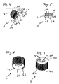
- FIGS. 6 to 10 show, likewise in different views, an exemplary cover 2 which is part of an exemplary closure device according to the invention or an exemplary tube according to the invention.
- the sleeve 1 has a first axial end 10 and a second axial end 12.
- the sleeve 1 is positionable on the tube neck of a tube and / or attachable to this.
- a tube may in particular be designed such that it has a tube body, which in turn has a tube shoulder and a tube neck.
- the sleeve can be moved in the direction of arrow 14 on this or plugged or Congressprellt. It can be provided in particular that the sleeve 1 is manufacturedprellt on such a tube neck.
- the radially outer surface or outer circumferential surface 16 of the sleeve 1 is provided with a thread 18.
- the sleeve 1 or its jacket wall 20 has a cylindrical or hollow cylindrical shaped portion 22. On the radially outer surface or outer circumferential surface of this cylindrical portion 22, the thread 18 is provided.
- a stop 24 and a first annular flange is provided.
- a designed as a (first) annular flange stop 24 is provided here.
- This stop 24 is an axial stop for the cover. 2
- This first annular flange or stop 24 is, as can be seen in FIG. 2, formed circumferentially closed.
- This first annular flange or stop 24 is designed substantially conically, in particular on the first end 10 of the sleeve 1 facing side. He has on its the first end 10 of the sleeve 1 side facing a slope 26. This slope runs - as seen from the direction of the first end 10 in the direction of the second end 12 - increasingly radially outward.
- the first annular flange or stop 24 is also designed substantially conically on the second end 12 of the sleeve 1 side facing. He has on this page on a slope 28 or bevels 28. These bevels 28 each extend - as seen from the direction of the first end 10 in the direction of the second end 12 - increasingly radially outward.
- the first annular flange or the stop 24 has recesses 30. These recesses 30 are provided on the second end 12 of the sleeve 1 facing side of the first annular flange and the stopper 24. These recesses 30 are disposed circumferentially spaced apart in the embodiment. This may for example be such that the distance between each circumferentially adjacent recesses 30 in the circumferential direction is the same in each case. It is provided in particular that in the direction of contact between the recesses each bevels 28 are given, which is for example well visible in Fig. 4.
- the first annular flange or stop 24 is, as can be seen for example in FIGS. 1 and 3, radially outward further than the thread 18 of the sleeve 1.
- the sleeve 1 has a passage opening 32, which can be seen clearly in FIG. 2, for example.
- the sleeve 1 On its radially inner surface 34, the sleeve 1 has a profiling 36.
- this profiling 36 is provided on the inner surface of the hollow cylindrical portion 22 of the shell wall 20 of the sleeve 1.
- This profiling 36 can, for example-as the exemplary embodiment shows-be formed by a multiplicity of circumferentially spaced ribs between which interspaces are respectively provided in the manner of depressions.
- this profiling 36 may be formed in the manner of a spline.
- these ribs or these wedges of the spline teeth run substantially parallel to the central longitudinal axis 38 of the sleeve 1.
- This profiling 36 is particularly intended for the formation of an anti-rotation, which - when the sleeve 1 is received on the tube neck of a tube - is formed between this sleeve 1 and this tube neck.
- a profiling be formed at the tube neck on the outer circumferential surface also a profiling be formed, for example, is also formed by circumferentially spaced to form recessed interstices ribs or of a kind formed on this outer circumferential surface of the tube neck splines.
- the sleeve 1 also has locking elements 40. These latching elements 40 are formed in particular in that axially in the direction of the first end 10 of the sleeve 1 adjacent to the radially inner ends 42 of the bevels 28 groove-like depressions 44 are formed in the radially inner surface 34 of the sleeve 1.
- a latching element of the tube body can be, for example, a peripheral bead provided on the tube neck, which is positioned, for example, axially in the vicinity of the tube shoulder.
- the sleeve 1 has a second annular flange 46, which is different from the first annular flange or the stop 24.
- This second annular flange 46 is designed ring-shaped.
- the second annular flange 46 extends concentrically with the cylindrical portion 22 of the sleeve 1.
- the second annular flange 46 is arranged so that it is in the region of the first end 10 of the sleeve 1 and from the first end 10 facing the end of the cylindrical portion 22 of the sleeve 1 extends radially inward.
- the second annular flange 46 extends substantially in a plane that is perpendicular to the central longitudinal axis 38 of the sleeve 1.
- the second annular flange 46 is used in particular for covering the annular end face of a tube neck.
- the lid 2 is designed as a double wall wall closure. It has two radially spaced walls 60, 62 which extend circumferentially about the central longitudinal axis 64 of the lid 2.
- the first 60 of these walls 60, 62 is opposite the second wall 62 of these walls 60. 62 is located radially inward, is cylindrical or hollow cylindrical.
- the second 62 of these walls 60, 62 is also cylindrical or hollow cylindrical in this embodiment. It can also be provided, for example, that in particular the second wall 62 is conical.
- the lid 2 has an upper cover 66. This is in particular designed so that the cover 2 is formed closed upwards.
- the top cover 66 has an annular, particularly flat, portion 68 which extends perpendicular to the central longitudinal axis 64 of the lid and radially connects the top of the second wall 62 to the top of the first wall 60.
- This annular portion 68 forms the upper end of the lid 2 and is arranged at the first axial end 70 of the lid 2.
- the first axial end 70 of the lid 2 may also be referred to as the upper end, while the other axial end of the lid, the second axial end 72, may also be referred to as the lower axial end.
- the top cover 66 Radially within the annular portion 68, the top cover 66 has a recess 74 that is substantially cylindrical in shape. From the bottom 76 of this recess 74 protrudes a pin-like projection 78 in the direction of the first end 70 of the lid 2. This thorn-like projection 78 is recessed in the recess 76 such that it does not protrude from this.
- the thorn-like projection 78 serves as a tool for piercing a protective film, which often close the removal opening or the tube neck of tubes prior to the first removal of medium, so as to make it provable, for example, that the tube has not been removed medium.
- the bottom 76 of the recess 74 has an annular portion 80 which extends in a plane perpendicular to the central longitudinal axis 64 of the lid plane. This annular portion 80 extends radially between the first wall 60 and the spike-like projection 78.
- a thread 82 is provided at the first wall 60 of the lid 2. This is provided on the radially inner surface 84 of the first wall 60.
- the thread 82 of the lid 2 which may also be referred to as a screw cap, is designed so that it can be screwed to the thread 18 of the sleeve 1.
- the thread 82 is disposed below the bottom 76 of the recess 76 or, viewed from the bottom 76 in the direction facing the second axial end 72, located on the first wall 60.
- a region 86 of the upper cover 66 which here is a surface area of the bottom 76 facing the second end 72 of the cover 2, can serve to seal the outlet opening of the tube. This is particularly so here that this region 86 presses with a correspondingly wide screwing of the lid 2 sealingly on an annular end face of the tube neck or on the second annular flange 46 of the sleeve 1 positioned between this region 86 and this end face or sealing this second annular flange 46 presses against this annular end face of the tube neck.
- the inner diameter of the first wall 60 is smaller than the outer diameter of the first annular flange or stop 24 of the sleeve 1.
- the cover 2 and here in particular the first wall 60 of the lid 2 has an area or section 88 which can abut axially against the first annular flange or stop 24, in particular with corresponding screwing of the lid 2 on the sleeve 1 ,
- this area or section 88 is substantially adapted to a section or area of the first annular flange or stop 24, with which the area or section 88 comes into contact when striking. It can also be provided that there is a shape adaptability between these areas or sections. This can for example be such that the shapes of these areas or sections adapt to one another under load.
- the first annular flange or stop 24 of the sleeve 1-as already mentioned above- has a bevel 26 or a conical region.
- the portion or area 88 of the cover 2 or the wall 60, which can abut the bevel 26 of the sleeve 1, is also formed as a bevel or conical.
- This slope which is formed in the region 88, is provided in the region of the end of the first wall 60 facing the second end 72 of the lid, namely on the radially inner surface of this first wall 60.
- the angle of inclination of the bevel provided in the area 88 relative to the central longitudinal pocket 64 preferably corresponds to the angle of inclination of the bevel 26 with respect to the central longitudinal axis 38.
- the angle of inclination of the bevel provided in the region 88 relative to the central longitudinal ash 64 is less than the angle of inclination of the bevel 26 relative to the central longitudinal axis 38.
- This may in particular be such that the first annular flange or stop 24 in such a way is formed compliant or - in particular elastically deformable - that the area with the slope 26 adapts under load to the shape of the arranged in the region 88 slope.
- the first wall 60 may include reinforcing ribs 91 extending, for example, parallel to the central longitudinal axis 64, distributed about the circumference of the wall 60.
- the second wall 62 of the lid 2 has on its radially outer surface 90 a profiling or ribbing 92, which is formed for example by a plurality of parallel to the central longitudinal axis 64 aligned ribs 94, such as the Fig. 9 shows.
- FIG. 11 shows an exemplary tube body 3 of an exemplary tube according to the invention.
- the left half of the tube body 3 is shown in Fig. 11 in a sectional view, and the right Tube body 3 is shown in Fig. 11 in a sectional view, and the right half of the tube body 3 is shown in Fig. 11 in view from the outside.
- the tube body 3 has a tube shoulder 100, and a tube neck 102.
- the tube body 3 bounded to form a container an inner space 104, in which medium, such as with pharmaceutically active ingredients added pastes or creams or gel, or pastes or creams or gels, the are not added to pharmaceutical agents, or foods such as mustard, ketchup, mayonnaise or the like can be included.
- the tube body 3 is made in one piece. It can be provided, for example, that the lower end or bottom of the tube body 3 by - in particular multiple - folding or winding is generated. It can also be provided that the tube body 3 - apart from a separately produced bottom - is made in one piece.
- the tube neck 102 is substantially cylindrically shaped.
- a profiling 108 which is here formed by a plurality of circumferentially spaced ribs, between which are given in each case in the manner of depressions interstices.
- the tube neck 102 has on its radially outer surface 106 a bead 110 which projects radially outward.
- This bead 110 is designed in particular as a circumferentially closed bead.
- a circumferential groove 112 is formed by means of this bead 110 and this tube shoulder.
- sleeve 1 is placed or committeeprellt in the direction of arrow 113 on the tube neck 102.
- the bead 110 of the tube neck snaps into the groove-like recess 44 of the sleeve or the radially inner end of the bevels 28 of the sleeve 2 in the groove-like recess 112 at the tube neck.
- the profiles 36 and 108 act together so that an anti-rotation is formed by which a rotation of the sleeve 1 relative to the tube neck 102 about the axis 38 and 114 is substantially prevented.
- the angle of inclination of the tube shoulder in this region 116 is essentially adapted to the angle of inclination of the bevels 28 or that it adapts under load.
- the sleeve 1 substantially completely covers the radially outer surface 106 of the tube neck.
- the lid 2 and the sleeve are each made of plastic.
Landscapes
- Engineering & Computer Science (AREA)
- Mechanical Engineering (AREA)
- Closures For Containers (AREA)
- Pipe Accessories (AREA)
- Infusion, Injection, And Reservoir Apparatuses (AREA)
- Making Paper Articles (AREA)
- Buffer Packaging (AREA)
Priority Applications (1)
| Application Number | Priority Date | Filing Date | Title |
|---|---|---|---|
| PL05016237T PL1632435T3 (pl) | 2004-09-06 | 2005-07-26 | Tuba i urządzenie zamykające do tub |
Applications Claiming Priority (1)
| Application Number | Priority Date | Filing Date | Title |
|---|---|---|---|
| DE102004043040A DE102004043040B4 (de) | 2004-09-06 | 2004-09-06 | Verschlusseinrichtung für Tuben und Tube |
Publications (2)
| Publication Number | Publication Date |
|---|---|
| EP1632435A1 EP1632435A1 (de) | 2006-03-08 |
| EP1632435B1 true EP1632435B1 (de) | 2007-12-19 |
Family
ID=34937912
Family Applications (1)
| Application Number | Title | Priority Date | Filing Date |
|---|---|---|---|
| EP05016237A Expired - Lifetime EP1632435B1 (de) | 2004-09-06 | 2005-07-26 | Tube und Verschlusseinrichtung für Tuben |
Country Status (5)
| Country | Link |
|---|---|
| EP (1) | EP1632435B1 (pl) |
| AT (1) | ATE381497T1 (pl) |
| DE (2) | DE102004043040B4 (pl) |
| ES (1) | ES2299929T3 (pl) |
| PL (1) | PL1632435T3 (pl) |
Families Citing this family (1)
| Publication number | Priority date | Publication date | Assignee | Title |
|---|---|---|---|---|
| FR3012349B1 (fr) * | 2013-10-29 | 2020-07-31 | Albea Services | Tete de tube comprenant un insert formant barriere |
Family Cites Families (6)
| Publication number | Priority date | Publication date | Assignee | Title |
|---|---|---|---|---|
| FR2037066A1 (pl) * | 1969-02-05 | 1970-12-31 | Minmetal Srl | |
| AU3505668A (en) * | 1969-03-17 | 1970-10-22 | Containers Limited | Improved collapsible tube |
| DE2153071A1 (de) * | 1971-10-25 | 1973-05-03 | Weener Plastik Meerguth & Co | Verschluss vorzugsweise fuer kunststofftuben, solche mit aus kunststoff bestehenden verschlussnippeln und flaschen |
| DE2907502A1 (de) * | 1978-06-09 | 1979-12-20 | Minmetal Srl | Vorrichtung zum verschliessen des mundstuecks einer eine pastenfoermige essware aufzunehmen faehigen biegsamen tube |
| DE8231867U1 (de) * | 1982-11-12 | 1983-03-17 | Automation Industrielle S.A., 1896 Vouvry | Verpackungstube |
| EP1026097B1 (de) * | 1999-01-26 | 2001-11-28 | Kunststoffwerk Mauer GmbH | Tube mit kindersicherem Verschluss |
-
2004
- 2004-09-06 DE DE102004043040A patent/DE102004043040B4/de not_active Expired - Fee Related
-
2005
- 2005-07-26 DE DE502005002272T patent/DE502005002272D1/de not_active Expired - Lifetime
- 2005-07-26 PL PL05016237T patent/PL1632435T3/pl unknown
- 2005-07-26 AT AT05016237T patent/ATE381497T1/de not_active IP Right Cessation
- 2005-07-26 EP EP05016237A patent/EP1632435B1/de not_active Expired - Lifetime
- 2005-07-26 ES ES05016237T patent/ES2299929T3/es not_active Expired - Lifetime
Also Published As
| Publication number | Publication date |
|---|---|
| DE102004043040A1 (de) | 2006-03-09 |
| PL1632435T3 (pl) | 2008-05-30 |
| DE102004043040B4 (de) | 2012-05-10 |
| EP1632435A1 (de) | 2006-03-08 |
| ATE381497T1 (de) | 2008-01-15 |
| ES2299929T3 (es) | 2008-06-01 |
| DE502005002272D1 (de) | 2008-01-31 |
Similar Documents
| Publication | Publication Date | Title |
|---|---|---|
| DE60223852T2 (de) | Kindersicherheitsverschluss und Verpackung | |
| EP2566768B1 (de) | Behältnis mit schraubverschluss | |
| DE3422546C2 (de) | Behälter-Verschlußkappe | |
| CH669575A5 (pl) | ||
| EP0520207A1 (de) | Flaschenverschlusskappe für Zwei-Komponenten-Packungen | |
| DE3041972A1 (de) | Verschlusskappe und verfahren zu ihrer herstellung | |
| DE29807243U1 (de) | Kindersicherer und originalitätsgesicherter Behälter-Verschluß | |
| DE69213666T2 (de) | Schnappscharnierverschluss für Spenderbehälter | |
| CH672625A5 (pl) | ||
| EP3829993B1 (de) | Tubenverpackung und verfahren zur deren herstellung | |
| WO2007031162A1 (de) | Garantieschraubverschluss für behälter und flaschen, insbesondere für kunststoffflaschen | |
| EP2307281A1 (de) | Tubenverpackung | |
| DE102010039036A1 (de) | Schraubverschluss mit Flexband | |
| EP1632435B1 (de) | Tube und Verschlusseinrichtung für Tuben | |
| EP3829992B1 (de) | Tubenverpackung | |
| DE202009017321U1 (de) | Behälter für pastöse oder halbfeste Produkte | |
| EP0060983B1 (de) | Behälter mit Sicherheitsverschluss | |
| EP0701949B1 (de) | Behälterverschluss mit Kindersicherung | |
| EP0319005A2 (de) | Mit einem Verschluss ausgestatteter Behälter | |
| EP1700790B1 (de) | Tube zur Aufnahme von pastösen Medien oder dergleichen | |
| DE19653065A1 (de) | Verpackung | |
| DE69903968T2 (de) | Aus einem behälter und einem hals hergestellte mehrteilige flasche, deren hals auf der behältermündung dichtend befestigt ist | |
| EP3838788B1 (de) | Dosier-verschlusseinrichtung für flaschen und kappenverschluss | |
| DE29801270U1 (de) | Ausgiesseinschweissteil | |
| CH620886A5 (en) | Container, which can be closed by means of a screw-on cap, with anti-opening lock |
Legal Events
| Date | Code | Title | Description |
|---|---|---|---|
| PUAI | Public reference made under article 153(3) epc to a published international application that has entered the european phase |
Free format text: ORIGINAL CODE: 0009012 |
|
| AK | Designated contracting states |
Kind code of ref document: A1 Designated state(s): AT BE BG CH CY CZ DE DK EE ES FI FR GB GR HU IE IS IT LI LT LU LV MC NL PL PT RO SE SI SK TR |
|
| AX | Request for extension of the european patent |
Extension state: AL BA HR MK YU |
|
| 17P | Request for examination filed |
Effective date: 20060807 |
|
| 17Q | First examination report despatched |
Effective date: 20060907 |
|
| AKX | Designation fees paid |
Designated state(s): AT BE BG CH CY CZ DE DK EE ES FI FR GB GR HU IE IS IT LI LT LU LV MC NL PL PT RO SE SI SK TR |
|
| GRAP | Despatch of communication of intention to grant a patent |
Free format text: ORIGINAL CODE: EPIDOSNIGR1 |
|
| RIN1 | Information on inventor provided before grant (corrected) |
Inventor name: SCHORNER, HORST |
|
| GRAS | Grant fee paid |
Free format text: ORIGINAL CODE: EPIDOSNIGR3 |
|
| GRAA | (expected) grant |
Free format text: ORIGINAL CODE: 0009210 |
|
| AK | Designated contracting states |
Kind code of ref document: B1 Designated state(s): AT BE BG CH CY CZ DE DK EE ES FI FR GB GR HU IE IS IT LI LT LU LV MC NL PL PT RO SE SI SK TR |
|
| REG | Reference to a national code |
Ref country code: GB Ref legal event code: FG4D Free format text: NOT ENGLISH |
|
| REG | Reference to a national code |
Ref country code: IE Ref legal event code: FG4D Free format text: LANGUAGE OF EP DOCUMENT: GERMAN |
|
| REG | Reference to a national code |
Ref country code: CH Ref legal event code: EP |
|
| REF | Corresponds to: |
Ref document number: 502005002272 Country of ref document: DE Date of ref document: 20080131 Kind code of ref document: P |
|
| PG25 | Lapsed in a contracting state [announced via postgrant information from national office to epo] |
Ref country code: SE Free format text: LAPSE BECAUSE OF FAILURE TO SUBMIT A TRANSLATION OF THE DESCRIPTION OR TO PAY THE FEE WITHIN THE PRESCRIBED TIME-LIMIT Effective date: 20080319 |
|
| REG | Reference to a national code |
Ref country code: CH Ref legal event code: NV Representative=s name: AMMANN PATENTANWAELTE AG BERN |
|
| PG25 | Lapsed in a contracting state [announced via postgrant information from national office to epo] |
Ref country code: LV Free format text: LAPSE BECAUSE OF FAILURE TO SUBMIT A TRANSLATION OF THE DESCRIPTION OR TO PAY THE FEE WITHIN THE PRESCRIBED TIME-LIMIT Effective date: 20071219 Ref country code: FI Free format text: LAPSE BECAUSE OF FAILURE TO SUBMIT A TRANSLATION OF THE DESCRIPTION OR TO PAY THE FEE WITHIN THE PRESCRIBED TIME-LIMIT Effective date: 20071219 Ref country code: NL Free format text: LAPSE BECAUSE OF FAILURE TO SUBMIT A TRANSLATION OF THE DESCRIPTION OR TO PAY THE FEE WITHIN THE PRESCRIBED TIME-LIMIT Effective date: 20071219 Ref country code: SI Free format text: LAPSE BECAUSE OF FAILURE TO SUBMIT A TRANSLATION OF THE DESCRIPTION OR TO PAY THE FEE WITHIN THE PRESCRIBED TIME-LIMIT Effective date: 20071219 Ref country code: LT Free format text: LAPSE BECAUSE OF FAILURE TO SUBMIT A TRANSLATION OF THE DESCRIPTION OR TO PAY THE FEE WITHIN THE PRESCRIBED TIME-LIMIT Effective date: 20071219 |
|
| REG | Reference to a national code |
Ref country code: PL Ref legal event code: T3 |
|
| REG | Reference to a national code |
Ref country code: ES Ref legal event code: FG2A Ref document number: 2299929 Country of ref document: ES Kind code of ref document: T3 |
|
| NLV1 | Nl: lapsed or annulled due to failure to fulfill the requirements of art. 29p and 29m of the patents act | ||
| GBV | Gb: ep patent (uk) treated as always having been void in accordance with gb section 77(7)/1977 [no translation filed] | ||
| PG25 | Lapsed in a contracting state [announced via postgrant information from national office to epo] |
Ref country code: IS Free format text: LAPSE BECAUSE OF FAILURE TO SUBMIT A TRANSLATION OF THE DESCRIPTION OR TO PAY THE FEE WITHIN THE PRESCRIBED TIME-LIMIT Effective date: 20080419 Ref country code: CZ Free format text: LAPSE BECAUSE OF FAILURE TO SUBMIT A TRANSLATION OF THE DESCRIPTION OR TO PAY THE FEE WITHIN THE PRESCRIBED TIME-LIMIT Effective date: 20071219 |
|
| ET | Fr: translation filed | ||
| PG25 | Lapsed in a contracting state [announced via postgrant information from national office to epo] |
Ref country code: RO Free format text: LAPSE BECAUSE OF FAILURE TO SUBMIT A TRANSLATION OF THE DESCRIPTION OR TO PAY THE FEE WITHIN THE PRESCRIBED TIME-LIMIT Effective date: 20071219 Ref country code: SK Free format text: LAPSE BECAUSE OF FAILURE TO SUBMIT A TRANSLATION OF THE DESCRIPTION OR TO PAY THE FEE WITHIN THE PRESCRIBED TIME-LIMIT Effective date: 20071219 |
|
| PG25 | Lapsed in a contracting state [announced via postgrant information from national office to epo] |
Ref country code: PT Free format text: LAPSE BECAUSE OF FAILURE TO SUBMIT A TRANSLATION OF THE DESCRIPTION OR TO PAY THE FEE WITHIN THE PRESCRIBED TIME-LIMIT Effective date: 20080519 |
|
| REG | Reference to a national code |
Ref country code: IE Ref legal event code: FD4D |
|
| PLBE | No opposition filed within time limit |
Free format text: ORIGINAL CODE: 0009261 |
|
| STAA | Information on the status of an ep patent application or granted ep patent |
Free format text: STATUS: NO OPPOSITION FILED WITHIN TIME LIMIT |
|
| PG25 | Lapsed in a contracting state [announced via postgrant information from national office to epo] |
Ref country code: IE Free format text: LAPSE BECAUSE OF FAILURE TO SUBMIT A TRANSLATION OF THE DESCRIPTION OR TO PAY THE FEE WITHIN THE PRESCRIBED TIME-LIMIT Effective date: 20071219 Ref country code: DK Free format text: LAPSE BECAUSE OF FAILURE TO SUBMIT A TRANSLATION OF THE DESCRIPTION OR TO PAY THE FEE WITHIN THE PRESCRIBED TIME-LIMIT Effective date: 20071219 |
|
| 26N | No opposition filed |
Effective date: 20080922 |
|
| PG25 | Lapsed in a contracting state [announced via postgrant information from national office to epo] |
Ref country code: GB Free format text: LAPSE BECAUSE OF FAILURE TO SUBMIT A TRANSLATION OF THE DESCRIPTION OR TO PAY THE FEE WITHIN THE PRESCRIBED TIME-LIMIT Effective date: 20071219 |
|
| PG25 | Lapsed in a contracting state [announced via postgrant information from national office to epo] |
Ref country code: GR Free format text: LAPSE BECAUSE OF FAILURE TO SUBMIT A TRANSLATION OF THE DESCRIPTION OR TO PAY THE FEE WITHIN THE PRESCRIBED TIME-LIMIT Effective date: 20080320 |
|
| PG25 | Lapsed in a contracting state [announced via postgrant information from national office to epo] |
Ref country code: MC Free format text: LAPSE BECAUSE OF NON-PAYMENT OF DUE FEES Effective date: 20080731 |
|
| PG25 | Lapsed in a contracting state [announced via postgrant information from national office to epo] |
Ref country code: EE Free format text: LAPSE BECAUSE OF FAILURE TO SUBMIT A TRANSLATION OF THE DESCRIPTION OR TO PAY THE FEE WITHIN THE PRESCRIBED TIME-LIMIT Effective date: 20071219 Ref country code: BG Free format text: LAPSE BECAUSE OF FAILURE TO SUBMIT A TRANSLATION OF THE DESCRIPTION OR TO PAY THE FEE WITHIN THE PRESCRIBED TIME-LIMIT Effective date: 20080319 |
|
| PG25 | Lapsed in a contracting state [announced via postgrant information from national office to epo] |
Ref country code: CY Free format text: LAPSE BECAUSE OF FAILURE TO SUBMIT A TRANSLATION OF THE DESCRIPTION OR TO PAY THE FEE WITHIN THE PRESCRIBED TIME-LIMIT Effective date: 20071219 |
|
| PG25 | Lapsed in a contracting state [announced via postgrant information from national office to epo] |
Ref country code: AT Free format text: LAPSE BECAUSE OF NON-PAYMENT OF DUE FEES Effective date: 20080726 |
|
| PG25 | Lapsed in a contracting state [announced via postgrant information from national office to epo] |
Ref country code: LU Free format text: LAPSE BECAUSE OF NON-PAYMENT OF DUE FEES Effective date: 20080726 Ref country code: BE Free format text: LAPSE BECAUSE OF NON-PAYMENT OF DUE FEES Effective date: 20080731 Ref country code: HU Free format text: LAPSE BECAUSE OF FAILURE TO SUBMIT A TRANSLATION OF THE DESCRIPTION OR TO PAY THE FEE WITHIN THE PRESCRIBED TIME-LIMIT Effective date: 20080620 |
|
| REG | Reference to a national code |
Ref country code: FR Ref legal event code: PLFP Year of fee payment: 12 |
|
| REG | Reference to a national code |
Ref country code: FR Ref legal event code: PLFP Year of fee payment: 13 |
|
| REG | Reference to a national code |
Ref country code: FR Ref legal event code: PLFP Year of fee payment: 14 |
|
| PGFP | Annual fee paid to national office [announced via postgrant information from national office to epo] |
Ref country code: FR Payment date: 20210721 Year of fee payment: 17 Ref country code: IT Payment date: 20210730 Year of fee payment: 17 |
|
| PGFP | Annual fee paid to national office [announced via postgrant information from national office to epo] |
Ref country code: ES Payment date: 20210819 Year of fee payment: 17 Ref country code: PL Payment date: 20210715 Year of fee payment: 17 Ref country code: TR Payment date: 20210716 Year of fee payment: 17 Ref country code: CH Payment date: 20210723 Year of fee payment: 17 Ref country code: DE Payment date: 20210721 Year of fee payment: 17 |
|
| REG | Reference to a national code |
Ref country code: DE Ref legal event code: R119 Ref document number: 502005002272 Country of ref document: DE |
|
| REG | Reference to a national code |
Ref country code: CH Ref legal event code: PL |
|
| PG25 | Lapsed in a contracting state [announced via postgrant information from national office to epo] |
Ref country code: LI Free format text: LAPSE BECAUSE OF NON-PAYMENT OF DUE FEES Effective date: 20220731 Ref country code: FR Free format text: LAPSE BECAUSE OF NON-PAYMENT OF DUE FEES Effective date: 20220731 Ref country code: CH Free format text: LAPSE BECAUSE OF NON-PAYMENT OF DUE FEES Effective date: 20220731 |
|
| PG25 | Lapsed in a contracting state [announced via postgrant information from national office to epo] |
Ref country code: DE Free format text: LAPSE BECAUSE OF NON-PAYMENT OF DUE FEES Effective date: 20230201 |
|
| PG25 | Lapsed in a contracting state [announced via postgrant information from national office to epo] |
Ref country code: IT Free format text: LAPSE BECAUSE OF NON-PAYMENT OF DUE FEES Effective date: 20220726 |
|
| REG | Reference to a national code |
Ref country code: ES Ref legal event code: FD2A Effective date: 20230830 |
|
| PG25 | Lapsed in a contracting state [announced via postgrant information from national office to epo] |
Ref country code: ES Free format text: LAPSE BECAUSE OF NON-PAYMENT OF DUE FEES Effective date: 20220727 |
|
| PG25 | Lapsed in a contracting state [announced via postgrant information from national office to epo] |
Ref country code: PL Free format text: LAPSE BECAUSE OF NON-PAYMENT OF DUE FEES Effective date: 20220726 |
|
| PG25 | Lapsed in a contracting state [announced via postgrant information from national office to epo] |
Ref country code: TR Free format text: LAPSE BECAUSE OF NON-PAYMENT OF DUE FEES Effective date: 20220726 |