EP1628853B1 - Crashaktive kopfstütze - Google Patents
Crashaktive kopfstütze Download PDFInfo
- Publication number
- EP1628853B1 EP1628853B1 EP04739345A EP04739345A EP1628853B1 EP 1628853 B1 EP1628853 B1 EP 1628853B1 EP 04739345 A EP04739345 A EP 04739345A EP 04739345 A EP04739345 A EP 04739345A EP 1628853 B1 EP1628853 B1 EP 1628853B1
- Authority
- EP
- European Patent Office
- Prior art keywords
- crash
- headrest
- tappet
- guide
- headrest according
- Prior art date
- Legal status (The legal status is an assumption and is not a legal conclusion. Google has not performed a legal analysis and makes no representation as to the accuracy of the status listed.)
- Expired - Lifetime
Links
Images

Classifications
-
- B—PERFORMING OPERATIONS; TRANSPORTING
- B60—VEHICLES IN GENERAL
- B60N—SEATS SPECIALLY ADAPTED FOR VEHICLES; VEHICLE PASSENGER ACCOMMODATION NOT OTHERWISE PROVIDED FOR
- B60N2/00—Seats specially adapted for vehicles; Arrangement or mounting of seats in vehicles
- B60N2/80—Head-rests
- B60N2/806—Head-rests movable or adjustable
- B60N2/838—Tiltable
- B60N2/853—Tiltable characterised by their adjusting mechanisms, e.g. electric motors
-
- B—PERFORMING OPERATIONS; TRANSPORTING
- B60—VEHICLES IN GENERAL
- B60N—SEATS SPECIALLY ADAPTED FOR VEHICLES; VEHICLE PASSENGER ACCOMMODATION NOT OTHERWISE PROVIDED FOR
- B60N2/00—Seats specially adapted for vehicles; Arrangement or mounting of seats in vehicles
- B60N2/80—Head-rests
- B60N2/888—Head-rests with arrangements for protecting against abnormal g-forces, e.g. by displacement of the head-rest
Definitions
- the invention relates to a headrest with the features of the preamble of claim 1.
- a headrest of this kind is in the US 2003/0057758 A1 described.
- a magnetically held spring is provided, which acts on a four-bar linkage and extends in the event of a crash by means of a spring lever.
- the four-bar linkage is frictionally held in normal use and can therefore be brought manually from the starting position in a further comfort position.
- the spring load By means of the spring load also a transfer from the starting position is possible in a further comfort position.
- Another crash-active headrest is in the FR 2 832 364 A1 described.
- the invention is based on the object to improve a headrest of the type mentioned. This object is achieved by a headrest with the features of claim 1. Advantageous embodiments are the subject of the dependent claims.
- the design of the headrest for at least one more comfort position has the advantage that the principle given mobility of the headrest can also be used to increase comfort.
- the initial position is a first comfort position. It can be taken in the event of a crash from any comfort position out a crash position.
- a motor, pneumatic or hydraulic drive is provided, this transition into the other comfort positions for the occupant can be done easily and without effort, especially while he is sitting, so that a change between manual setting and debugging for iterative approach to the Ideal position is eliminated.
- the - Including the starting position - at least two comfort positions are therefore not approached manually, but by means of the drive. In order to keep the transition from the starting position (or another comfort position) in the crash position regardless of the transition from the starting position to another comfort position, different drives are provided for these two transitions, so a total of two drives.
- the drive acts via a guide plunger in the manner of an arm or via a spindle-spindle nut system on the kinematics of the headrest, so that favorable leverage ratios can be achieved.
- a pivotable adjusting lever can be effective between the drive and the guide tappet, since such is easy to couple to an engine or a cylinder.
- the guide tappet preferably has a tappet portion, which on the four-bar link or on a transverse connector between the four joints provided abuts and the or the four joints applied in the extension direction.
- a tappet portion which on the four-bar link or on a transverse connector between the four joints provided abuts and the or the four joints applied in the extension direction.
- a four-joint acting on the return spring next to the guide tappet is arranged, including an arrangement around the guide tappet to be understood. If no value is placed on the return movement, a clip connection or the like can keep the guide tappet retracted.
- the guide plunger preferably also has a guide portion which has a smaller diameter relative to the plunger portion, so that it can be detached from the four-bar link or cross connector.
- the preferably stepped transition region between the different diameters can serve as a stop.
- the inventively provided drive can also be used to extend the headrest before the crash in the crash position, for example, to a signal of a pre-crash sensor out due to small distances of the vehicle to the front man or Hintermann or a strong braking an imminent Crash detects.
- the triggering of the crash function by a triggering unit provided for this purpose preferably remains completely intact and superimposes the comfort setting function and the pre-crash function. Even if the baffle element is fully extended, then the crash function is triggered by the said trip unit in the event of a crash.
- a reversible reset of the headrest after a crash allows a new use of the headrest, which saves material and workshop costs.
- the occupant can reset the headrest itself, which in turn saves on workshop costs.
- a resetter for example, an integrated in the headrest, movable tension, pressure or rotary member or provided after a crash in the headrest tool is provided.
- the resetter brings the crash lock - and possibly a magnetic release - back to the starting position.
- An integrated in the headrest resetter is preferably visible only after the crash, to preclude premature operation.
- a trained as a tool resetter is preferably inserted in its longitudinal direction in the headrest, so that it has a substantially elongated basic shape and thus is easy to stow when not in use.
- a design of the energy storage as a tensioned spring has the advantage that enough energy can be stored for such a spring for a quick extension of the four-bar linkage with such a spring.
- Holding this tensioned spring by means of a pivotable pawl which is done directly or indirectly by holding an acted upon by the spring element, has the advantage that the spring is held on the one hand in relation to the pawl positively and on the other hand created by a suitable alignment of the pawl favorable leverage be so that the holding force can be made low.
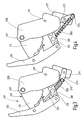
- a headrest 201 is provided for a vehicle seat of a motor vehicle.
- the headrest 201 is adjustable in height by means of two parallel headrest rods 203, which are slidably mounted in the backrest of the vehicle seat.
- the headrest rods 203 are inserted with their upper end fixed in a transverse to the headrest rods 203 arranged carrier 205.
- At the upper end of the carrier 205 is a horizontally disposed, extending transversely to the headrest rods 203 axis 207 stored in the carrier 205.
- a pair of upper wings 211 are pivotally mounted, which are spaced from each other and have an approximately triangular basic shape, wherein the axis 207 is disposed in a corner of each upper rocker 211.
- the upper wings 211 are parallel to each other forward and downward. In the foremost corner of each upper rocker 211 the latter is articulated at the upper end of a common impact element 213, which is arranged in front of the carrier 205 in the direction of travel.
- the baffle 213 consists essentially of two laterally bent legs, which together two parallel to the axis 207 extending crossbeams are connected. For manufacturing reasons, made as a plastic injection molded part impact element 213 may be composed of two substantially mirror-image halves.
- a cushion member is arranged, wherein the baffle 213 may be the cushion support at the same time, ie, the pad may be attached directly to the baffle 213.
- a pair of lower wings 215 of elongated shape are articulated on the one hand in each case by means of a horizontal, parallel to the axis 207 rocker bearing bolt 217 on the carrier 205 and on the other hand at the lower end of the impact member 213.
- the carrier 205, the upper rocker 211, the baffle 213 and the lower rocker 215 each form a four-bar linkage 219.
- the lower rocker 215 is longer than the upper rocker 211, so that the upper rocker 211 and the lower rocker 215 are not parallel ,
- the upper rocker 211 and the associated lower rocker 215 do not pivot in the same plane, but are offset from each other according to the bend of the baffle element 213.
- a catch plate not shown in detail is pivotally mounted on the axis 207, which is acted upon by a likewise not shown double leg spring on a retaining bolt by a likewise not shown, pivoting pawl.
- the latch in turn is kept locked by a magnetic holding device.
- Each upper rocker 211 carries a sawtooth-type crash lock toothing, which is designed to cooperate with in each case one of the carrier 205 hinged crash barrier part. Crash barrier gearing and crash barrier part together form a crash barrier.
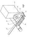
- a servomotor 271 is mounted, which consists of an electric motor and a gear reduction.
- the servomotor 271 takes with a horizontally arranged shaft with a rotatably mounted adjusting lever 273.
- the adjusting lever protrudes 273 diagonally down and behind.
- At the free end of the adjusting lever 273 is parallel to the shaft from a rotatable about its longitudinal axis adjusting bolt 275 from which an end of a guide plunger 277 is attached.
- the guide plunger 277 consists of a cylindrical plunger portion 277 'having a first diameter and a likewise cylindrical, with the plunger portion 277' aligned guide portion 277 "having a second diameter which is smaller than the first diameter.
- the guide tappet 277 is arranged so that the tappet portion 277 'is disposed between the adjusting bolt 275 and the cross connector 281 and the guide portion 277 "is inserted through a radial transverse bore of the cross connector 281.
- the step formed transition between the tappet portion 277' and the guide portion 277 "serves for the transverse connector 281 as a stop to the rear, wherein a hinged between the adjusting bolt 275 and the transverse connector 281, arranged next to the guide plunger 277 return spring 283 pulls the cross connector 281 against this stop.
- the headrest 201 has three functions, namely a crash function, a comfort setting function and a pre-crash function.
- a double-leg spring acting as an energy store (drive) is released via a control, the holding mechanism and the pawl, which presses on the impact element by means of the catch plate and by means of the four joints 219 on the two sides of the headrest 201 in the very best position, the so-called crash position, extends.
- the crash barrier secures the four-pivot 219 against a renewed retraction due to an impact of the head of the occupant on the baffle 213.
- the headrest 201 can be reversibly reset by releasing the crash lock.
- the adjusting lever 273 is pivoted with the adjusting bolt 275 by the servomotor 271 serving as a drive.
- the transverse connector 281 is subjected to pressure in the extension direction by means of the tappet section 277 'of the guide tappet 277 when the adjusting lever 273 pivots forward (in the clockwise direction) ,
- a retraction of the baffle element 213 back into a rear comfort position or in the starting position is withdrawn with a pivoting movement of the adjusting lever 273 to the rear (in the drawing counterclockwise) of the cross connector 281 via the return spring 283 in the retraction direction.
- the servo motor 271 receives the signal from its control in the event of an imminent crash to make an extension according to the comfort adjustment described above, but beyond the foremost comfort position into the crash position, in which the adjustment lever 273 points forward , If there is still enough time or no crash, this crash position is also achieved. Otherwise, the crash function is superimposed, i. the baffle element 213 is carried along by the double leg spring, the guide section 277 "of the guide tappet 277 allowing forward free movement of the transverse connector 281 together with the four hinges 219. The transverse connector 281 then moves away from the step between the guide section 277" and the tappet section 277 '. and approaches the free end of the guide tappet 277.
- the baffle element 213 can be extended in the event of a crash if the pre-crash function has not been activated. In all cases, the restoring force of the return spring 283 is negligible with respect to the force of the double leg spring.
Landscapes
- Engineering & Computer Science (AREA)
- Aviation & Aerospace Engineering (AREA)
- Transportation (AREA)
- Mechanical Engineering (AREA)
- Seats For Vehicles (AREA)
- Chair Legs, Seat Parts, And Backrests (AREA)
Applications Claiming Priority (2)
| Application Number | Priority Date | Filing Date | Title |
|---|---|---|---|
| DE10325472A DE10325472A1 (de) | 2003-06-05 | 2003-06-05 | Crashaktive Kopfstütze |
| PCT/EP2004/005631 WO2004108472A1 (de) | 2003-06-05 | 2004-05-26 | Crashaktive kopfstütze |
Publications (2)
| Publication Number | Publication Date |
|---|---|
| EP1628853A1 EP1628853A1 (de) | 2006-03-01 |
| EP1628853B1 true EP1628853B1 (de) | 2010-09-08 |
Family
ID=33482573
Family Applications (1)
| Application Number | Title | Priority Date | Filing Date |
|---|---|---|---|
| EP04739345A Expired - Lifetime EP1628853B1 (de) | 2003-06-05 | 2004-05-26 | Crashaktive kopfstütze |
Country Status (5)
| Country | Link |
|---|---|
| US (1) | US7195313B2 (enExample) |
| EP (1) | EP1628853B1 (enExample) |
| JP (1) | JP2006526535A (enExample) |
| DE (2) | DE10325472A1 (enExample) |
| WO (1) | WO2004108472A1 (enExample) |
Families Citing this family (50)
| Publication number | Priority date | Publication date | Assignee | Title |
|---|---|---|---|---|
| DE102004035582B3 (de) | 2004-07-22 | 2006-02-02 | Keiper Gmbh & Co.Kg | Crashaktive Kopfstütze |
| US7644987B2 (en) | 2004-09-27 | 2010-01-12 | Lear Corporation | Vehicle seat having active head restraint system |
| JP4436238B2 (ja) * | 2004-11-26 | 2010-03-24 | トヨタ紡織株式会社 | ヘッドレスト |
| DE102005009128B3 (de) * | 2005-03-01 | 2006-06-22 | Keiper Gmbh & Co.Kg | Verfahren zum Zusammenbau einer crashaktiven Kopfstütze |
| JP4690085B2 (ja) * | 2005-03-23 | 2011-06-01 | アイシン精機株式会社 | ヘッドレスト |
| JP4770314B2 (ja) * | 2005-07-27 | 2011-09-14 | アイシン精機株式会社 | 車両用シート装置 |
| JP4818661B2 (ja) * | 2005-08-25 | 2011-11-16 | アイシン精機株式会社 | 車両用ヘッドレスト装置 |
| JP4294629B2 (ja) * | 2005-10-17 | 2009-07-15 | アイシン精機株式会社 | ヘッドレスト装置 |
| DE102005051423B3 (de) * | 2005-10-27 | 2007-03-08 | Keiper Gmbh & Co.Kg | Crashaktive Kopfstütze |
| DE102006001143B3 (de) * | 2006-01-06 | 2007-04-19 | Johnson Controls Gmbh | Kopfstütze, insbesondere für ein Kraftfahrzeug |
| JP4342521B2 (ja) * | 2006-01-30 | 2009-10-14 | アイシン精機株式会社 | ヘッドレスト装置 |
| US7621598B2 (en) * | 2006-10-03 | 2009-11-24 | Lear Corporation | Adjustable head restraint for a vehicle seat |
| US7455357B2 (en) * | 2006-10-04 | 2008-11-25 | Lear Corporation | Active head restraint system for a vehicle seat |
| DE102006055185B4 (de) * | 2006-11-21 | 2010-06-02 | Keiper Gmbh & Co. Kg | Crashaktives System eines Fahrzeugs |
| ES1064266Y (es) * | 2006-12-05 | 2007-05-16 | Batz S Coop | Reposacabezas para asientos de vehiculos automoviles |
| US7374239B1 (en) * | 2007-01-16 | 2008-05-20 | Ford Global Technologies, Inc. | Active head restraint with self resetting mechanism |
| US7845721B2 (en) * | 2007-02-14 | 2010-12-07 | Inoac Corporation | Headrest |
| ES2304100B1 (es) * | 2007-02-16 | 2009-07-03 | Batz , S. Coop. | "reposacabezas para asientos de vehiculos automoviles". |
| US7992933B2 (en) * | 2007-06-21 | 2011-08-09 | Lear Corporation | Integrated vehicle seat with active head restraint system |
| US20090001792A1 (en) * | 2007-06-29 | 2009-01-01 | Lear Corporation | Head restraint system for a vehicle seat |
| DE102007048151B3 (de) * | 2007-09-04 | 2009-01-22 | Lear Corporation, Southfield | Einstellbare Kopfstütze für einen Fahrzeugsitz |
| US7871129B2 (en) * | 2007-12-05 | 2011-01-18 | Lear Corporation | Seat assembly having an adjustable head restraint assembly |
| US8100472B2 (en) * | 2008-03-17 | 2012-01-24 | Lear Corporation | Vehicle active head restraint system with a locking linkage |
| JP5262356B2 (ja) * | 2008-07-01 | 2013-08-14 | トヨタ紡織株式会社 | 車両用シート |
| US8205941B2 (en) * | 2008-07-30 | 2012-06-26 | Trw Vehicle Safety Systems Inc. | Active head restraint for a vehicle seat |
| DE102008057792B4 (de) * | 2008-11-17 | 2013-08-14 | Johnson Controls Gmbh | Crashaktive Kopfstütze mit einem sperrenden Druckknopf |
| DE102010003109B9 (de) * | 2009-04-22 | 2012-12-13 | Lear Corporation | Sitzanordnung mit beweglicher Kopfstütze |
| DE102009020117B4 (de) * | 2009-05-06 | 2013-11-14 | Lear Corp. | Sitzanordnung und verstellbare Kopfstützenanordnung |
| DE102010002525B9 (de) * | 2009-05-28 | 2012-12-13 | Lear Corp. | Sitzbaugruppe mit einer beweglichen Kopfstützen-Baugruppe |
| DE102009045833A1 (de) * | 2009-10-20 | 2011-05-26 | Lear Corp., Southfield | Sitzeinrichtung mit einer einstellbaren Kopfstützeneinrichtung |
| DE102009046660B4 (de) * | 2009-11-12 | 2011-11-10 | Lear Corporation | Sitzanordnung mit einer beweglichen Kopfstütze |
| DE102010023403B4 (de) * | 2010-06-11 | 2012-09-27 | Johnson Controls Gmbh | Kopfstütze, insbesondere für ein Kraftfahrzeug |
| US8657378B2 (en) | 2010-10-04 | 2014-02-25 | Lear Corporation | Seat assembly having an adjustable head restraint assembly |
| DE102011005590B4 (de) | 2011-03-16 | 2013-05-16 | Lear Corporation | Sitzanordnung mit einer beweglichen Kopflehnenanordnung |
| DE102011006243B4 (de) | 2011-03-28 | 2016-11-17 | Lear Corporation | Höhenverstellbare Kopfstütze für Fahrzeugsitze |
| ES2399306B1 (es) * | 2011-05-23 | 2014-01-28 | Batz, S.Coop. | Reposacabezas para asientos de vehículos automóviles. |
| JP6107459B2 (ja) * | 2013-06-18 | 2017-04-05 | トヨタ紡織株式会社 | 乗物用シート |
| KR101576377B1 (ko) * | 2014-07-01 | 2015-12-11 | 현대다이모스(주) | 헤드레스트 리클라이닝 모듈 |
| US9730522B2 (en) | 2014-09-26 | 2017-08-15 | L&P Property Management Company | Headrest tilt mechanism |
| US9949567B2 (en) | 2014-09-26 | 2018-04-24 | L&P Property Management Company | Reversible headrest tilt, lumbar mechanism |
| US9987958B2 (en) * | 2015-10-26 | 2018-06-05 | Ford Global Technologies, Llc | Quick disconnect headrest |
| CN108367696B (zh) * | 2015-11-30 | 2020-08-18 | B/E航空公司 | 前向平移头枕 |
| US9789794B1 (en) | 2016-07-19 | 2017-10-17 | Ford Global Technologies, Llc | Active head restraint |
| JP6879864B2 (ja) * | 2017-08-25 | 2021-06-02 | 日本発條株式会社 | ヘッドレスト装置 |
| DE102018109611B4 (de) * | 2018-04-10 | 2022-04-21 | Grammer Aktiengesellschaft | Kopfstütze |
| EP3552875A1 (de) * | 2018-04-10 | 2019-10-16 | Grammer Ag | Kopfstütze |
| US20200207246A1 (en) * | 2018-12-28 | 2020-07-02 | Windsor Machine and Stamping (2009) Ltd. | Head restraint with active deployment |
| US20200247276A1 (en) * | 2019-02-05 | 2020-08-06 | Windsor Machine and Stamping (2009) Ltd. | Electric power actuation tilting head restraint with automated deployment |
| US11124101B2 (en) * | 2019-03-15 | 2021-09-21 | Eric B. Fromer | Safe landing headrest |
| US11987158B2 (en) | 2022-07-05 | 2024-05-21 | GM Global Technology Operations LLC | Energy absorbing headrest for a vehicle |
Family Cites Families (37)
| Publication number | Priority date | Publication date | Assignee | Title |
|---|---|---|---|---|
| US3586366A (en) | 1969-04-21 | 1971-06-22 | American Safety Equip | Inertia-responsive retractable head restraint device |
| DE2206329C2 (de) | 1972-02-10 | 1984-06-14 | Adam Opel AG, 6090 Rüsselsheim | Kopfstütze für Kraftfahrzeugsitze |
| DE3138851A1 (de) | 1981-09-30 | 1983-04-14 | Bayerische Motoren Werke AG, 8000 München | Kopfstuetze in personenkraftfahrzeugen |
| FR2583361B1 (fr) | 1985-06-12 | 1987-09-04 | Faure Bertrand | Perfectionnements aux appuis-tete reglables et aux sieges equipes de tels appuis-tete |
| GB2194729B (en) * | 1986-09-04 | 1990-03-14 | Gen Motors Corp | Improved vehicle headrest |
| DE3900495A1 (de) | 1989-01-10 | 1990-07-26 | Bayerische Motoren Werke Ag | Kopfstuetze fuer einen kraftfahrzeugsitz |
| US5181763A (en) | 1990-09-20 | 1993-01-26 | Ronald P. Dellanno | Apparatus for preventing whiplash |
| DE29603467U1 (de) | 1996-02-26 | 1996-06-20 | Trw Occupant Restraint Systems Gmbh, 73551 Alfdorf | Fahrzeugsitz |
| FR2746065B1 (fr) | 1996-03-18 | 1998-05-22 | Appui-tete pour siege de vehicule automobile | |
| DE29614238U1 (de) | 1996-08-16 | 1996-12-12 | Trw Occupant Restraint Systems Gmbh, 73551 Alfdorf | Kopfstütze für einen Fahrzeugsitz |
| DE19707998B4 (de) * | 1997-02-27 | 2007-04-05 | Inova Gmbh Technische Entwicklungen | Kraftfahrzeugsitz |
| NO304221B1 (no) | 1996-12-02 | 1998-11-16 | Jacob Kalleberg | Sikringssystem for kj°ret°y |
| JPH10278648A (ja) | 1997-04-10 | 1998-10-20 | Yasushi Goto | 自動車用鞭打ち症防止機構付ヘッドレスト |
| DE19757533C2 (de) | 1997-12-23 | 2000-02-10 | Brose Fahrzeugteile | Sicherheits-Fahrzeugsitz |
| US6074011A (en) | 1998-03-16 | 2000-06-13 | Johnson Controls Technology Company | Automatic retractable head restraint |
| JPH11321502A (ja) | 1998-05-20 | 1999-11-24 | Daihatsu Motor Co Ltd | 自動車用シ−トのヘッドレストレイント |
| EP0976608A1 (en) | 1998-07-09 | 2000-02-02 | Gestind M.B. Manifattura Di Bruzolo S.P.A | A headrest for motor-vehicle seats |
| ES2188060T3 (es) | 1998-07-23 | 2003-06-16 | Grammer Automotive Gmbh | Reposacabezas para los asientos de los vehiculos automoviles. |
| DE29907245U1 (de) | 1999-04-23 | 1999-08-26 | TRW Occupant Restraint Systems GmbH & Co. KG, 73553 Alfdorf | Aufblasbare Kopfstütze |
| DE19923659C2 (de) * | 1999-05-22 | 2003-06-05 | Grammer Ag | Kopfstütze für einen Fahrzeugsitz |
| US6213548B1 (en) | 1999-08-12 | 2001-04-10 | Trw Inc. | Head restraint apparatus |
| DE50004441D1 (de) | 1999-08-17 | 2003-12-18 | Johnson Controls Gmbh | Rückenlehne für einen Fahrzeugsitz mit einer integrierten Schutzeinrichtung |
| DE19938904A1 (de) * | 1999-08-17 | 2001-03-08 | Johnson Controls Gmbh | Fahrzeugsitz-Rückenlehne mit integrierter Schutzeinrichtung und Verfahren zur Vorbeugung gegen unfallbedingte Verletzungen |
| US6203105B1 (en) | 1999-08-20 | 2001-03-20 | Mccord Winn Textron Inc. | Vehicle impact responsive multiple bladder seating and headrest system and method |
| DE19951966B4 (de) * | 1999-10-28 | 2006-11-02 | Bayerische Motoren Werke Ag | Fahrzeugsitz mit einer an der Rückenlehne oder am Fahrzeugaufbau vorgesehenen Kopfstütze |
| DE10001329B4 (de) | 2000-10-05 | 2004-07-08 | Faurecia Autositze Gmbh & Co. Kg | Rückenlehne eines Kraftfahrzeugsitzes |
| DE10004766B4 (de) | 2000-02-03 | 2004-10-28 | Keiper Gmbh & Co. Kg | Kopfstütze für einen Fahrzeugsitz |
| DE10012973B4 (de) * | 2000-03-16 | 2004-02-26 | Daimlerchrysler Ag | Kopfstütze für einen Fahrzeugsitz |
| DE10026978C1 (de) | 2000-05-31 | 2001-10-18 | Ise Gmbh | Überrollschutzvorrichtung für Kraftfahrzeuge mit einer lektrisch verstellbaren Kopfstütze |
| US6715829B2 (en) * | 2000-06-15 | 2004-04-06 | Autoliv Development Ab | Head-rest |
| US6824212B2 (en) * | 2000-08-24 | 2004-11-30 | Lear Corporation | Vehicle seat |
| DE10047406A1 (de) * | 2000-09-26 | 2002-04-11 | Daimler Chrysler Ag | Kopfstütze |
| BR0204278A (pt) | 2001-02-24 | 2003-02-18 | Keiper Gmbh & Co | Encosto de cabeça para assento de veìculo |
| FR2832364B1 (fr) * | 2001-11-21 | 2004-05-28 | Cera | Appui-tete a systeme d'actionnement de securite |
| DE10202598B4 (de) * | 2002-01-24 | 2005-03-10 | Keiper Gmbh & Co Kg | Kopfstütze für einen Fahrzeugsitz |
| DE10215054B4 (de) | 2002-04-05 | 2007-01-18 | Keiper Gmbh & Co.Kg | Kopfstütze für einen Fahrzeugsitz |
| WO2004056606A1 (de) | 2002-12-21 | 2004-07-08 | Keiper Gmbh & Co. Kg | Crashaktive kopfstütze |
-
2003
- 2003-06-05 DE DE10325472A patent/DE10325472A1/de not_active Ceased
-
2004
- 2004-05-26 EP EP04739345A patent/EP1628853B1/de not_active Expired - Lifetime
- 2004-05-26 JP JP2006508202A patent/JP2006526535A/ja not_active Ceased
- 2004-05-26 WO PCT/EP2004/005631 patent/WO2004108472A1/de not_active Ceased
- 2004-05-26 DE DE502004011641T patent/DE502004011641D1/de not_active Expired - Lifetime
-
2005
- 2005-11-23 US US11/287,578 patent/US7195313B2/en not_active Expired - Lifetime
Also Published As
| Publication number | Publication date |
|---|---|
| DE502004011641D1 (de) | 2010-10-21 |
| DE10325472A1 (de) | 2004-12-30 |
| US20060071518A1 (en) | 2006-04-06 |
| WO2004108472A1 (de) | 2004-12-16 |
| US7195313B2 (en) | 2007-03-27 |
| EP1628853A1 (de) | 2006-03-01 |
| JP2006526535A (ja) | 2006-11-24 |
Similar Documents
| Publication | Publication Date | Title |
|---|---|---|
| EP1628853B1 (de) | Crashaktive kopfstütze | |
| EP1572494B1 (de) | Crashaktive kopfstütze | |
| EP1535794B1 (de) | Kopfstütze für Kraftfahrzeugsitze | |
| DE69716445T2 (de) | Sitzrückenlehnemechanismus | |
| EP1276634A1 (de) | Kopfstütze für einen fahrzeugsitz | |
| EP0752344B1 (de) | Ausfahrbarer Überrollbügel | |
| WO2014075819A1 (de) | Fahrzeugsitz, insbesondere kraftfahrzeugsitz | |
| DE10260582B3 (de) | Crashaktive Kopfstütze | |
| EP1427601B2 (de) | Kraftfahrzeugsitz | |
| DE19961617C2 (de) | Rückenlehne für einen Fahrzeugsitz | |
| DE10109162B4 (de) | Kopfstütze für ein Fahrzeugsitz | |
| DE102005003289B4 (de) | Fahrzeugsitz mit Bodenstellung | |
| DE202006005525U1 (de) | Sitzschienenpaar für einen Fahrzeugsitz | |
| EP1877276B1 (de) | Verstelleinrichtung für ein kraftfahrzeug | |
| EP1584513B1 (de) | Crashaktive Kopfstütze | |
| EP1332066B1 (de) | Gelenkhebelkonstruktion für ein sitzgestell | |
| DE102005033344B3 (de) | Crashaktive Kopfstütze | |
| DE10124662B4 (de) | Kopfstütze für einen Fahrzeugsitz | |
| DE102006015922B4 (de) | Sitzschienenpaar für einen Fahrzeugsitz | |
| DE10109160B4 (de) | Kopfstütze für einen Fahrzeugsitz | |
| EP3280614B1 (de) | Längseinsteller für einen fahrzeugsitz und fahrzeugsitz | |
| DE202005020672U1 (de) | Fahrzeugsitz, insbesondere Kraftfahrzeugsitz | |
| DE10038778B4 (de) | Fahrzeugsitz, insbesondere Kraftfahrzeugsitz | |
| DE102004035583A1 (de) | Crashaktive Kopfstütze | |
| EP4412867A1 (de) | Vorrichtung zum schnellen rotieren einer baugruppe eines fahrzeugsitzes |
Legal Events
| Date | Code | Title | Description |
|---|---|---|---|
| PUAI | Public reference made under article 153(3) epc to a published international application that has entered the european phase |
Free format text: ORIGINAL CODE: 0009012 |
|
| 17P | Request for examination filed |
Effective date: 20050309 |
|
| AK | Designated contracting states |
Kind code of ref document: A1 Designated state(s): DE FR GB IT |
|
| DAX | Request for extension of the european patent (deleted) | ||
| RBV | Designated contracting states (corrected) |
Designated state(s): DE FR GB IT |
|
| 17Q | First examination report despatched |
Effective date: 20081107 |
|
| RAP1 | Party data changed (applicant data changed or rights of an application transferred) |
Owner name: KEIPER GMBH & CO. KG |
|
| GRAP | Despatch of communication of intention to grant a patent |
Free format text: ORIGINAL CODE: EPIDOSNIGR1 |
|
| GRAS | Grant fee paid |
Free format text: ORIGINAL CODE: EPIDOSNIGR3 |
|
| GRAA | (expected) grant |
Free format text: ORIGINAL CODE: 0009210 |
|
| AK | Designated contracting states |
Kind code of ref document: B1 Designated state(s): DE FR GB IT |
|
| REG | Reference to a national code |
Ref country code: GB Ref legal event code: FG4D Free format text: NOT ENGLISH |
|
| REF | Corresponds to: |
Ref document number: 502004011641 Country of ref document: DE Date of ref document: 20101021 Kind code of ref document: P |
|
| PG25 | Lapsed in a contracting state [announced via postgrant information from national office to epo] |
Ref country code: IT Free format text: LAPSE BECAUSE OF FAILURE TO SUBMIT A TRANSLATION OF THE DESCRIPTION OR TO PAY THE FEE WITHIN THE PRESCRIBED TIME-LIMIT Effective date: 20100908 |
|
| PLBE | No opposition filed within time limit |
Free format text: ORIGINAL CODE: 0009261 |
|
| STAA | Information on the status of an ep patent application or granted ep patent |
Free format text: STATUS: NO OPPOSITION FILED WITHIN TIME LIMIT |
|
| 26N | No opposition filed |
Effective date: 20110609 |
|
| REG | Reference to a national code |
Ref country code: DE Ref legal event code: R097 Ref document number: 502004011641 Country of ref document: DE Effective date: 20110609 |
|
| REG | Reference to a national code |
Ref country code: DE Ref legal event code: R081 Ref document number: 502004011641 Country of ref document: DE Owner name: JOHNSON CONTROLS COMPONENTS GMBH & CO. KG, DE Free format text: FORMER OWNER: KEIPER GMBH & CO. KG, 67657 KAISERSLAUTERN, DE Effective date: 20140710 Ref country code: DE Ref legal event code: R081 Ref document number: 502004011641 Country of ref document: DE Owner name: ADIENT LUXEMBOURG HOLDING S.A.R.L., LU Free format text: FORMER OWNER: KEIPER GMBH & CO. KG, 67657 KAISERSLAUTERN, DE Effective date: 20140710 Ref country code: DE Ref legal event code: R081 Ref document number: 502004011641 Country of ref document: DE Owner name: ADIENT LUXEMBOURG HOLDING S.A R.L., LU Free format text: FORMER OWNER: KEIPER GMBH & CO. KG, 67657 KAISERSLAUTERN, DE Effective date: 20140710 |
|
| REG | Reference to a national code |
Ref country code: FR Ref legal event code: PLFP Year of fee payment: 13 |
|
| REG | Reference to a national code |
Ref country code: DE Ref legal event code: R081 Ref document number: 502004011641 Country of ref document: DE Owner name: ADIENT US LLC, PLYMOUTH, US Free format text: FORMER OWNER: JOHNSON CONTROLS COMPONENTS GMBH & CO. KG, 67657 KAISERSLAUTERN, DE Ref country code: DE Ref legal event code: R081 Ref document number: 502004011641 Country of ref document: DE Owner name: ADIENT LUXEMBOURG HOLDING S.A.R.L., LU Free format text: FORMER OWNER: JOHNSON CONTROLS COMPONENTS GMBH & CO. KG, 67657 KAISERSLAUTERN, DE Ref country code: DE Ref legal event code: R081 Ref document number: 502004011641 Country of ref document: DE Owner name: ADIENT LUXEMBOURG HOLDING S.A R.L., LU Free format text: FORMER OWNER: JOHNSON CONTROLS COMPONENTS GMBH & CO. KG, 67657 KAISERSLAUTERN, DE |
|
| REG | Reference to a national code |
Ref country code: FR Ref legal event code: PLFP Year of fee payment: 14 |
|
| REG | Reference to a national code |
Ref country code: DE Ref legal event code: R079 Ref document number: 502004011641 Country of ref document: DE Free format text: PREVIOUS MAIN CLASS: B60N0002480000 Ipc: B60N0002800000 |
|
| REG | Reference to a national code |
Ref country code: DE Ref legal event code: R081 Ref document number: 502004011641 Country of ref document: DE Owner name: ADIENT US LLC, PLYMOUTH, US Free format text: FORMER OWNER: ADIENT LUXEMBOURG HOLDING S.A.R.L., LUXEMBOURG, LU Ref country code: DE Ref legal event code: R081 Ref document number: 502004011641 Country of ref document: DE Owner name: ADIENT LUXEMBOURG HOLDING S.A R.L., LU Free format text: FORMER OWNER: ADIENT LUXEMBOURG HOLDING S.A.R.L., LUXEMBOURG, LU |
|
| REG | Reference to a national code |
Ref country code: FR Ref legal event code: PLFP Year of fee payment: 15 |
|
| REG | Reference to a national code |
Ref country code: GB Ref legal event code: 732E Free format text: REGISTERED BETWEEN 20210121 AND 20210127 |
|
| REG | Reference to a national code |
Ref country code: GB Ref legal event code: 732E Free format text: REGISTERED BETWEEN 20210128 AND 20210203 |
|
| REG | Reference to a national code |
Ref country code: DE Ref legal event code: R081 Ref document number: 502004011641 Country of ref document: DE Owner name: ADIENT US LLC, PLYMOUTH, US Free format text: FORMER OWNER: ADIENT LUXEMBOURG HOLDING S.A R.L., LUXEMBOURG, LU |
|
| PGFP | Annual fee paid to national office [announced via postgrant information from national office to epo] |
Ref country code: GB Payment date: 20220527 Year of fee payment: 19 Ref country code: FR Payment date: 20220525 Year of fee payment: 19 Ref country code: DE Payment date: 20220527 Year of fee payment: 19 |
|
| REG | Reference to a national code |
Ref country code: DE Ref legal event code: R119 Ref document number: 502004011641 Country of ref document: DE |
|
| GBPC | Gb: european patent ceased through non-payment of renewal fee |
Effective date: 20230526 |
|
| PG25 | Lapsed in a contracting state [announced via postgrant information from national office to epo] |
Ref country code: DE Free format text: LAPSE BECAUSE OF NON-PAYMENT OF DUE FEES Effective date: 20231201 Ref country code: GB Free format text: LAPSE BECAUSE OF NON-PAYMENT OF DUE FEES Effective date: 20230526 |
|
| PG25 | Lapsed in a contracting state [announced via postgrant information from national office to epo] |
Ref country code: FR Free format text: LAPSE BECAUSE OF NON-PAYMENT OF DUE FEES Effective date: 20230531 |