EP1624092A1 - Verchromtes Auspuff - Google Patents
Verchromtes Auspuff Download PDFInfo
- Publication number
- EP1624092A1 EP1624092A1 EP05017075A EP05017075A EP1624092A1 EP 1624092 A1 EP1624092 A1 EP 1624092A1 EP 05017075 A EP05017075 A EP 05017075A EP 05017075 A EP05017075 A EP 05017075A EP 1624092 A1 EP1624092 A1 EP 1624092A1
- Authority
- EP
- European Patent Office
- Prior art keywords
- plating layer
- chromium plating
- chromium
- engine part
- metal substrate
- Prior art date
- Legal status (The legal status is an assumption and is not a legal conclusion. Google has not performed a legal analysis and makes no representation as to the accuracy of the status listed.)
- Withdrawn
Links
Images


Classifications
-
- F—MECHANICAL ENGINEERING; LIGHTING; HEATING; WEAPONS; BLASTING
- F01—MACHINES OR ENGINES IN GENERAL; ENGINE PLANTS IN GENERAL; STEAM ENGINES
- F01N—GAS-FLOW SILENCERS OR EXHAUST APPARATUS FOR MACHINES OR ENGINES IN GENERAL; GAS-FLOW SILENCERS OR EXHAUST APPARATUS FOR INTERNAL COMBUSTION ENGINES
- F01N13/00—Exhaust or silencing apparatus characterised by constructional features ; Exhaust or silencing apparatus, or parts thereof, having pertinent characteristics not provided for in, or of interest apart from, groups F01N1/00 - F01N5/00, F01N9/00, F01N11/00
- F01N13/16—Selection of particular materials
-
- C—CHEMISTRY; METALLURGY
- C25—ELECTROLYTIC OR ELECTROPHORETIC PROCESSES; APPARATUS THEREFOR
- C25D—PROCESSES FOR THE ELECTROLYTIC OR ELECTROPHORETIC PRODUCTION OF COATINGS; ELECTROFORMING; APPARATUS THEREFOR
- C25D5/00—Electroplating characterised by the process; Pretreatment or after-treatment of workpieces
- C25D5/10—Electroplating with more than one layer of the same or of different metals
- C25D5/12—Electroplating with more than one layer of the same or of different metals at least one layer being of nickel or chromium
- C25D5/14—Electroplating with more than one layer of the same or of different metals at least one layer being of nickel or chromium two or more layers being of nickel or chromium, e.g. duplex or triplex layers
-
- C—CHEMISTRY; METALLURGY
- C25—ELECTROLYTIC OR ELECTROPHORETIC PROCESSES; APPARATUS THEREFOR
- C25D—PROCESSES FOR THE ELECTROLYTIC OR ELECTROPHORETIC PRODUCTION OF COATINGS; ELECTROFORMING; APPARATUS THEREFOR
- C25D5/00—Electroplating characterised by the process; Pretreatment or after-treatment of workpieces
- C25D5/60—Electroplating characterised by the structure or texture of the layers
- C25D5/605—Surface topography of the layers, e.g. rough, dendritic or nodular layers
- C25D5/611—Smooth layers
-
- C—CHEMISTRY; METALLURGY
- C25—ELECTROLYTIC OR ELECTROPHORETIC PROCESSES; APPARATUS THEREFOR
- C25D—PROCESSES FOR THE ELECTROLYTIC OR ELECTROPHORETIC PRODUCTION OF COATINGS; ELECTROFORMING; APPARATUS THEREFOR
- C25D5/00—Electroplating characterised by the process; Pretreatment or after-treatment of workpieces
- C25D5/60—Electroplating characterised by the structure or texture of the layers
- C25D5/615—Microstructure of the layers, e.g. mixed structure
- C25D5/617—Crystalline layers
-
- C—CHEMISTRY; METALLURGY
- C25—ELECTROLYTIC OR ELECTROPHORETIC PROCESSES; APPARATUS THEREFOR
- C25D—PROCESSES FOR THE ELECTROLYTIC OR ELECTROPHORETIC PRODUCTION OF COATINGS; ELECTROFORMING; APPARATUS THEREFOR
- C25D5/00—Electroplating characterised by the process; Pretreatment or after-treatment of workpieces
- C25D5/60—Electroplating characterised by the structure or texture of the layers
- C25D5/615—Microstructure of the layers, e.g. mixed structure
- C25D5/619—Amorphous layers
-
- C—CHEMISTRY; METALLURGY
- C25—ELECTROLYTIC OR ELECTROPHORETIC PROCESSES; APPARATUS THEREFOR
- C25D—PROCESSES FOR THE ELECTROLYTIC OR ELECTROPHORETIC PRODUCTION OF COATINGS; ELECTROFORMING; APPARATUS THEREFOR
- C25D5/00—Electroplating characterised by the process; Pretreatment or after-treatment of workpieces
- C25D5/627—Electroplating characterised by the visual appearance of the layers, e.g. colour, brightness or mat appearance
-
- C—CHEMISTRY; METALLURGY
- C25—ELECTROLYTIC OR ELECTROPHORETIC PROCESSES; APPARATUS THEREFOR
- C25D—PROCESSES FOR THE ELECTROLYTIC OR ELECTROPHORETIC PRODUCTION OF COATINGS; ELECTROFORMING; APPARATUS THEREFOR
- C25D7/00—Electroplating characterised by the article coated
- C25D7/04—Tubes; Rings; Hollow bodies
-
- Y—GENERAL TAGGING OF NEW TECHNOLOGICAL DEVELOPMENTS; GENERAL TAGGING OF CROSS-SECTIONAL TECHNOLOGIES SPANNING OVER SEVERAL SECTIONS OF THE IPC; TECHNICAL SUBJECTS COVERED BY FORMER USPC CROSS-REFERENCE ART COLLECTIONS [XRACs] AND DIGESTS
- Y10—TECHNICAL SUBJECTS COVERED BY FORMER USPC
- Y10T—TECHNICAL SUBJECTS COVERED BY FORMER US CLASSIFICATION
- Y10T29/00—Metal working
- Y10T29/49—Method of mechanical manufacture
- Y10T29/49345—Catalytic device making
Definitions
- the present invention relates to an engine part, and more particularly, the present invention relates to an engine part which is subjected to a high temperature due to a high-temperature exhaust gas discharged from an engine.
- FIG. 10 is a side view showing an example of a sports-type motorcycle.
- a motorcycle 200 shown in FIG. 10 includes a V-type engine 201 and an exhaust pipe 202 for guiding along exhaust gas.
- the V-type engine 201 includes cylinders 203, cylinder heads 204, and head covers 205.
- the aesthetically excellent V-type engine 201 is likely to be mounted to the motorcycle such that the engine is exposed on the outside, and is highly influential to the exterior appearance of the entire motorcycle.
- the two cylinders 203 of the V-type engine 201 are united at the single exhaust pipe 202, which extends toward and above the rear wheel so as to allow exhaust gas to be discharged at the rear portion of the body.
- the exhaust pipe 202 must have a certain thickness for allowing the exhaust gas generated in the engine 201 to be efficiently discharged.
- the portion constituting a muffler 202a has an increased diameter in order to accommodate the muffling structure.
- the exhaust pipe accounts for a relatively large part of the exterior appearance of the entire motorcycle, and thus the shape and color of the exhaust pipe are highly influential to the entire motorcycle design.
- engine components such as the cylinders 203, the cylinder heads 204, the head covers 205, as well as the exhaust pipe 202 for guiding the exhaust gas from the engine, will be generally referred to as "engine parts".
- engine parts the shape and color of engine parts are important factors in determining the entire motorcycle design.
- decorative chromium plating provides an excellent metallic luster, and also excels in anticorrosiveness, it is also used in various fields other than engine parts. In order to obtain excellent exterior appearance and anticorrosiveness, it is unnecessary to provide a thick layer of decorative chromium plating. In fact, a thick layer of decorative chromium plating will result in a poor color tone and surface finish. Therefore, in general, decorative chromium plating is likely to be used at a thickness in the range from 0.1 ⁇ m to 0.15 ⁇ m.
- hard chromium plating (industrial chromium plating) is also widely used as Cr plating in industrial products. Since hard chromium plating provides a low friction coefficient and an excellent abrasion resistance, it is used for sliding sections of various machine parts, for example. Since abrasion resistance is a requirement, hard chromium plating is usually formed to a thickness of at least several ⁇ m. Moreover, hard chromium plating does not provide a decorativeness surface as does decorative chromium plating.
- decorative chromium plating provides a surface roughness (Ra) of about 1 ⁇ m or less (typically, about 0.2 ⁇ m or less), while hard chromium plating provides a surface roughness of more than about 1 ⁇ m.
- the surface of the chromium plating layer may change its color tone to result in a violet discoloration, or the decorative chromium plating layer may have cracks and then peel.
- the engine performance has improved, and catalysts have been used for exhaust gas purification, and as a result the exhaust gas temperature has increased.
- engine parts are becoming more susceptible to discoloration due to high-temperature exhaust gas.
- engine parts account for a relatively large portion of the overall exterior appearance of the entire motorcycle. Therefore, even a muddy spot on the chromium plating may greatly impair the entire design.
- This problem may be addressed by preventing the temperature of the surface of the exhaust pipe or the like from becoming too high, by adopting a two-fold or three-fold cylindrical structure for the exhaust pipe, for example.
- a two-fold or three-fold cylindrical structure for the exhaust pipe, for example.
- the temperature of the exhaust pipe surface will not be adequately lowered, and surface oxidation or deterioration due to heat will not be completely prevented.
- a decorative chromium plating layer is usually formed by using a chromate, including hexavalent chromium (Cr 6+ ). Hexavalent chromium is inexpensive. A decorative chromium plating layer obtained by using hexavalent chromium shows good contact with a base substrate, and has excellent anticorrosiveness and abrasion resistance. A chromium plating layer obtained by using hexavalent chromium has a silver-gray color with a characteristically metallic luster. Therefore, hexavalent chromium is widely used in engine parts for motorcycles, for example. However, its toxic nature has been recognized in the recent years.
- trivalent chromium Cr 3+
- trivalent chromium is inferior to hexavalent chromium in terms of anticorrosiveness, contact with the base substrate, and the like
- environmental pollution concerns and safety-oriented thinking have led to the trends toward selective use of trivalent chromium.
- trivalent chromium replacing hexavalent chromium is also becoming popular in the field of engine parts.
- a motorcycle having a trivalent chromium-plated protector provided on the outer periphery of a muffler has recently been developed.
- a decorative chromium plating layer obtained by using trivalent chromium has a slightly blackish color tone.
- Such a difference in color tone can be highly problematic in the field of motorcycles and the like, where exterior appearance is regarded as important. Therefore, there is a desire for engine parts which, even by using trivalent chromium, attain a similar color tone to that which is obtained by using hexavalent chromium.
- preferred embodiments of the present invention provide engine parts which prevent the surface discoloration/deterioration associated with a high-temperature exhaust gas, irrespective of the type of Cr used in the formation of a chromium plating layer (hexavalent chromium or trivalent chromium). Also, preferred embodiments of the present invention also provide engine parts which, even by using trivalent chromium, attain a similar color tone to that which is obtained by using hexavalent chromium.
- An engine part includes a metal substrate, a chromium plating layer covering at least a region of a surface of the metal substrate, the region being heated to a temperature of about 350 °C or more, and an intermediate plating layer provided between the metal substrate and the chromium plating layer, wherein the chromium plating layer has a thickness of about 0.2 ⁇ m or more in the region.
- the chromium plating layer has a thickness in a range from about 0.2 to about 0.9 ⁇ m in the region.
- the chromium plating layer has a thickness in a range from about 0.2 to about 0.5 ⁇ . m in the region.
- the metal substrate is a metal tube defining a passage through which an exhaust gas from an engine travels.
- the chromium plating layer covers an outer side surface of the metal tube.
- the metal tube has a bent portion, and the region is a convex surface formed as a result of the bending of the bent portion.
- the metal tube includes a manifold section having a plurality of branch pipes connected thereto, and the region is an outer surface of the manifold section.
- the metal tube has a catalyst accommodating section accommodating a catalytic apparatus for decomposing at least one component in the exhaust gas, and the region is an outer surface of the catalyst accommodating section.
- the chromium plating layer includes decorative chromium plating.
- the intermediate plating layer includes at least one of C and S.
- the intermediate plating layer also includes Ni.
- the intermediate plating layer includes a metal having a hardness lower than that of a type of Cr composing the chromium plating layer.
- the intermediate plating layer includes nickel plating.
- the metal substrate is composed of a material containing Fe, Al, Zn, Mg, or Ti as a main component.
- the chromium plating layer is formed by using a hexavalent chromium plating bath.
- the chromium plating layer is formed by using a trivalent chromium plating bath.
- an engine part includes a metal substrate, a chromium plating layer covering at least a portion of a surface of the metal substrate, and an intermediate plating layer provided between the metal substrate and the chromium plating layer, wherein a type of Cr composing the chromium plating layer substantially has an amorphous structure, and an Fe content in the chromium plating layer is about 2 mass% or less.
- the chromium plating layer has a color tone such that an L* value measured according to CIE (Commision Internationale de l'Eclairage) 1976 is in a range from 68 to 80.
- CIE Commission Internationale de l'Eclairage
- the chromium plating layer covers a region of the surface of the metal substrate, the region being heated to a temperature of about 350 °C or more, and the chromium plating layer has a thickness in a range from about 0.2 ⁇ m to about 0.6 ⁇ m in the region.
- the metal substrate is a metal tube defining a passage through which an exhaust gas from an engine travels.
- the chromium plating layer covers at least a portion of an outer side surface of the metal tube.
- the metal tube has a bent portion, and the region is a convex surface formed as a result of the bending of the bent portion.
- the metal tube includes a manifold section having a plurality of branch pipes connected thereto, and the region is an outer surface of the manifold section.
- the metal tube has a catalyst accommodating section accommodating a catalytic apparatus for decomposing at least one component in the exhaust gas, and the region is an outer surface of the catalyst accommodating section.
- the chromium plating layer includes decorative chromium plating.
- the intermediate plating layer includes at least one of C and S.
- the intermediate plating layer also includes Ni.
- the intermediate plating layer includes a metal having a hardness lower than that of a type of Cr composing the chromium plating layer.
- the intermediate plating layer includes nickel plating.
- the metal substrate is composed of a material containing Fe, Al, Zn, Mg, or Ti as a main component.
- An engine according to another preferred embodiment of the present invention includes any of the aforementioned engine parts according to preferred embodiments described above.
- An exhaust pipe includes a metal tube having a bent portion, and a decorative chromium plating layer arranged to cover at least an outer convex surface being formed as a result of the bending of the bent portion, the decorative chromium plating layer having a thickness of about 0.2 ⁇ m or more.
- the metal tube includes a manifold section having a plurality of branch pipes connected thereto, and a catalyst accommodating section accommodating a catalytic apparatus, and the decorative chromium plating layer further covers an outside of the manifold section and the catalyst accommodating section.
- the chromium plating layer has a thickness in the range from about 0.2 to about 0.5 ⁇ m.
- the chromium plating layer has a color tone such that an L* value measured according to CIE (Commision Internationale de l'Eclairage) 1976 is in a range from 68 to 80.
- CIE Commission Internationale de l'Eclairage
- a transportation apparatus includes any of the aforementioned exhaust pipes according to preferred embodiments described above.
- a method of producing an engine part according to a further preferred embodiment of the present invention includes the steps of placing a metal substrate in a plating apparatus; forming an intermediate plating layer on the metal substrate, and using a chromium plating bath, performing plating while placing the metal substrate with the intermediate plating layer formed thereon in such a manner that a chromium plating layer having a thickness of about 0.2 ⁇ m or more is formed in a region of a surface of the metal substrate, the region being heated to a temperature of about 350 °C or more.
- an Fe content in the chromium plating layer is suppressed to about 2 mass% or less by controlling an Fe content in the chromium plating bath to be substantially zero.
- the chromium plating bath does not contain any additive having an Fe component.
- Fe contained in the chromium plating bath is removed by using a cation exchange resin.
- the thickness of a chromium plating layer is appropriately controlled in a region which is heated to a high temperature, so that discoloration of the plating layer due to heating can be prevented.
- a chromium plating layer formed by using trivalent chromium attains a silver-gray color tone similar to that which is obtained by using hexavalent chromium, thus providing excellent luster.
- the chromium plating layer has a high anticorrosiveness, and prevents rust.
- FIG. 1 is a diagram schematically showing the structure of an engine part according to a preferred embodiment of the present invention.
- FIG. 2A is a graph showing X-ray diffraction analysis results of a chromium plating layer formed by using trivalent chromium.
- FIG. 2B is a graph showing X-ray diffraction analysis results of a chromium plating layer formed by using hexavalent chromium.
- FIG. 3 is a diagram schematically showing the generation of a "C-S thickened layer" or a “C-S-Ni thickened layer”, obtained by heating, near an interface between a chromium plating layer and an intermediate plating layer.
- FIG. 4A is a schematic diagram for explaining prevention of discoloration of a chromium plating layer by increasing the thickness of the chromium plating layer.
- FIG. 4B is a diagram schematically showing a portion of a conventional Cr-nickel plating layer.
- FIG. 5 is a side view showing a motorcycle in which an engine part according to a preferred embodiment of the present invention is used.
- FIG. 6A is a diagram schematically showing a portion of an exhaust pipe which is directly connected to an engine.
- FIG. 6B is a diagram schematically showing a cross section of a catalyst accommodating section of an exhaust pipe.
- FIG. 6C is a diagram schematically showing a cross section of a manifold section.
- FIG. 7 is a diagram showing an example of a chromium plating apparatus used in a preferred embodiment of the present invention.
- FIG. 8A is a diagram schematically showing an arrangement in which a minimum distance exists between a curved portion of a metal substrate and an electrode.
- FIG. 8B is a diagram schematically showing an arrangement in which a long distance exists between a curved portion of a metal substrate and an electrode.
- FIG. 9A indicates photographs each showing a chromium plating layer formed by using a trivalent chromium plating bath which contains no ferrous sulfate, the chromium plating layer having been heated.
- FIG. 9B indicates photographs each showing a chromium plating layer formed by using a conventional trivalent chromium plating bath which contains ferrous sulfate, the chromium plating layer having been heated.
- FIG. 10 is a side view showing the exterior appearance of a motorcycle.
- the inventor has sought engine parts which can prevent discoloration of a decorative chromium plating layer and surface deterioration associated with a high-temperature exhaust gas.
- "discoloration" of a chromium plating layer refers to a change in the color of the surface of the plating layer from silver-gray to blue or violet.
- the inventor has also sought engine parts which, even when a decorative chromium plating layer is formed thereon by using trivalent chromium, attain a color tone similar to that of a chromium plating layer which is obtained by using hexavalent chromium.
- a decorative chromium plating is accompanied with an intermediate plating layer which is present between the chromium plating layer and a base substrate, in order to achieve an enhanced contact with the base substrate. Accordingly, the inventor's study has been directed to engine parts having such a structure. In the following, decorative chromium plating will simply be referred to as "chromium plating”.
- the surface discoloration of the chromium plating layer is mainly attributable to the fact that the C (carbon) and/or S (sulfur) which is supplied from the intermediate plating layer diffuses due to heating, and gathers near the interface between the intermediate plating layer and the chromium plating layer so as to thicken (thus forming a "C-S thickened layer"). It has also been determined that, in the case where a nickel plating layer is formed as an intermediate plating layer, the Ni which is contained in the nickel plating layer also joins the aforementioned C and S elements to form a "C-S-Ni thickened layer", thus contributing to the surface discoloration of the chromium plating layer.
- the elements which have thickened in the plating cause a change in the refractive index and/or light absorption (with respect to incident light) of the chromium plating.
- the discoloration caused by such a change is more conspicuous than the interference colors caused by the usually-occurring oxide coating on the outermost surface of a chromium plating layer.
- the inventor has looked for a method of preventing such surface discoloration, and thus found that the unfavorable influence of the "C-S thickened layer" or "C-S-Ni thickened layer” can be minimized at least by controlling the thickness of a portion of the chromium plating layer that is heated by the high-temperature exhaust gas so as to be within a predetermined range greater than a conventional thickness, because the increased thickness of the chromium plating layer prevents the light entering the chromium plating layer from reaching the thickened layer.
- the main cause for the blackish color tone of a chromium plating layer obtained by using trivalent chromium has been found to be the Fe which is contained in the chromium plating layer. This has led to the finding that, by minimizing the Fe content in the chromium plating layer, a chromium plating layer obtained by using trivalent chromium is able to attain a color tone similar to that which is obtained by using hexavalent chromium.
- CASS Copper-Accelerated Acetic Acid Salt Spray
- the engine part according to a preferred embodiment of the present invention preferably includes a metal substrate 1, a chromium plating layer 3 covering the surface of the metal substrate 1, and an intermediate plating layer 2 provided between the metal substrate 1 and the chromium plating layer 3.
- the chromium plating layer covers at least a region of the surface of the metal substrate 1 that is to be heated to a temperature of about 350 °C or more.
- the metal substrate 1 which has a mechanical strength suitable to its purpose and a necessary level of anticorrosiveness and the like, can be formed from a material which is usually used for an engine part.
- a typical example would be an Fe-type material.
- the metal substrate 1 may be formed from any non-Fe material, such as an Al-type material, a Zn-type material, an Mg-type material, or a Ti-type material.
- Fe-type materials include Fe or steels whose main component is Fe, such as: steel tubes for machine structural purposes (e.g., carbon steel tubes for machine structural purposes (STKM) or alloy steels for machine structural purposes); stainless steel (e.g., ferrite-type stainless steel, austenite-type stainless steel, or austenite/ferrite-type stainless steel); and mild steel (e.g., SPCC or SPHC).
- steel tubes for machine structural purposes e.g., carbon steel tubes for machine structural purposes (STKM) or alloy steels for machine structural purposes
- stainless steel e.g., ferrite-type stainless steel, austenite-type stainless steel, or austenite/ferrite-type stainless steel
- mild steel e.g., SPCC or SPHC
- Al-type materials include: Al; and Al alloys such as Al-Si alloys or Al-Si-Mg-type alloys.
- Zn-type materials include: Zn; Zn-plated steel plates, on which a Zn plating layer is provided; and Zn alloy-plated steel plates, on which a Zn alloy plating layer whose main component is Zn and which includes alloying elements such as Ni, Co, Cr, or Al is provided.
- Mg-type materials include Mg-Al type alloys and Mg-Zn type alloys.
- Ti-type materials include: Ti; and Ti alloys whose main component is Ti and which includes elements such as Al, V, or Si.
- Al is light-weight and shiny
- Ti is light weight and has excellent mechanical strength. Therefore, any appropriate material may be selected depending on the purpose, required characteristics, and the like.
- the intermediate plating layer 2 formed on the metal substrate 1 defines a an underlying plating for the chromium plating layer 3.
- an intermediate plating layer is usually formed under the chromium plating layer in order to realize good contact with the base substrate. Therefore, it is preferable that the intermediate plating layer exhibits good contact with various metal substrates, as well as good contact with the chromium plating layer. There might be other preferable characteristics of the intermediate plating layer, e.g., anticorrosiveness, and so on.
- the metal composing the intermediate plating layer 2 used for preferred embodiments of the present invention can be defined in terms of a relationship with the hardness (Vickers hardness) of Cr, which in itself is used for forming the chromium plating layer. Specifically, it is preferable that the metal composing the intermediate plating layer 2 is formed of a metal having a hardness lower than the hardness of Cr (about 400 Hv to about 1200 Hv).
- the presence of a layer composed of a low-hardness metal interposed between the chromium plating layer and the metal substrate reduces the stress applied to the chromium plating layer due to heat cycles. As a result, the generation of cracks and the like is prevented, and a chromium plating layer having good surface characteristics can be obtained.
- metals having a lower hardness than that of Cr include Ni (hardness: about 150 Hv to about 400 Hv), Cu (hardness: about 40 Hv to about 250 Hv), Sn (hardness: about 20 Hv to about 200 Hv), and Pb (whose hardness is immeasurable).
- an intermediate plating layer including such metals for example, a layer composed of nickel plating, Cu plating, Sn plating, Pb plating, Zn-nickel plating, or the like is preferably used.
- a single such plating layer may be formed, or two or more kinds may be combined to result in there being a plurality of intermediate plating layers.
- a plurality of intermediate plating layers of the same kind but containing different types of additives, etc. may be formed.
- a typical intermediate plating layer to be used as the underlying layer for a chromium plating layer is nickel plating, which further enhances anticorrosiveness, luster, and the like. The details of nickel plating will be described later.
- the intermediate plating layer 2 includes elements which compose various additives. With the purpose of enhancing the luster of the chromium plating layer, such additives are added in a plating bath for forming the intermediate plating layer 2. Specifically, a primary brightener (a non-butyne-type brightener, e.g., saccharin sodium, naphthalene-1,3,6-trisodium trisulfonate, or benzene sulfonic acid), a secondary brightener (e.g., 2-butyl-1,4-diol, sodium allylsulfonate), and the like are preferably used. Any such additive preferably includes C and/or S as its component elements.
- a primary brightener a non-butyne-type brightener, e.g., saccharin sodium, naphthalene-1,3,6-trisodium trisulfonate, or benzene sulfonic acid
- a secondary brightener
- a total of about 0.001 mass% to about 1.0 mass% of C and/or S is preferably included in the intermediate plating layer. As will be specifically described later, these elements will thicken to about 0.1 mass% to about 10 mass% responsive to heating, thus causing surface discoloration of the chromium plating layer. Furthermore, in the case where the intermediate plating layer 2 is a nickel plating layer, the Ni contained in the nickel plating layer also substantially affects surface discoloration.
- Nickel plating will be specifically described as a typical example of an intermediate plating layer.
- Nickel plating is generally classified into lusterless nickel plating, semigloss nickel plating, and gloss nickel plating, mainly depending on the type of brightener added in the plating bath, whether such an addition is made or not, etc. These types of plating can be appropriately combined in accordance with the required characteristics, purpose, and the like, whereby the desired exterior appearance can be obtained.
- Gloss nickel plating is obtained by adding a brightener such as saccharin or benzene sulfonic acid to the plating bath.
- Gloss nickel plating provides an excellent surface leveling (planarize) action and exhibits good contact with the chromium plating layer, and therefore is widely used as an underlying layer to be formed directly under a chromium plating layer.
- a brightener for gloss nickel plating is usually used in an amount such that a total of about 0.001 mass% to about 1.0 mass% of at least one of C and S is included in the plating layer. Anticorrosiveness tends to decrease as the S content increases.
- Lusterless nickel plating differs from gloss nickel plating in that no brightener is contained in the plating bath. Although providing less luster than gloss nickel plating, lusterless nickel plating is excellent in terms of throwing power, anticorrosiveness, discoloration prevention, etc., of the plating layer. It is to be noted that the "throwing power" refers to the ability to form uniform layer of plating metal.
- Semigloss nickel plating is obtained by adding a non-coumarin-type semi-brightener to the plating bath. Unlike the aforementioned brighteners, semi-brighteners have little C and/or S content. Therefore, semigloss nickel plating provides better anticorrosiveness but poorer luster than those provided by gloss nickel plating.
- a tri-nickel plating layer (which is a type of gloss nickel plating layer) having a large S content may be formed between the semigloss nickel plating layer and the gloss nickel plating layer, thus obtaining a three-layer plating structure.
- the S contained in the tri-nickel plating layer is most often supplied from an additive other than a brightener.
- the uppermost gloss nickel plating layer is corroded first, and then the intermediate tri-nickel plating layer is corroded, whereby both the semigloss nickel plating layer and the base metal are protected.
- the nickel plating layer(s) preferably has a total thickness of about 10 ⁇ m to about 30 ⁇ m, and more preferably no less than about 15 ⁇ m and no more than about 25 ⁇ m.
- the intermediate plating layer is preferably controlled to a thickness of about 10 ⁇ m to about 30 ⁇ m. 3. Chromium plating layer
- the chromium plating layer 3 is formed on the intermediate plating layer 2.
- the type of Cr used for forming the chromium plating layer 3 there are no particular limitations as to the type of Cr used for forming the chromium plating layer 3, and either trivalent chromium or hexavalent chromium may be used.
- the chromium plating layer 3 may be formed by trivalent chromium plating or hexavalent chromium plating.
- FIGS. 2A and 2B each show X-ray diffraction analysis results of a chromium plating layer. The detailed measurement method was as follows.
- Measurement conditions A Cu anticathode was used, and power was supplied at about 40kV/40mA.
- X-ray diffraction results of a chromium plating layer which has been formed by using hexavalent chromium are shown in FIG. 2B .
- Near diffraction angles of about 40 ⁇ to 50 ⁇ a very large diffraction peak of about 1200 cps is observed, and large diffraction peaks of about 200 cps are observed near diffraction angles of about 65 ⁇ and about 830 ⁇ In the ascending order of diffraction angles, these peaks correspond to (111) orientation crystal, (200) orientation crystal, and (211) orientation crystal, respectively.
- FIG. 2A X-ray diffraction results of a chromium plating layer which has been formed by using trivalent chromium are shown in FIG. 2A .
- a value obtained by dividing the half-width of the peak corresponding to (111) orientation crystal by the peak intensity (half-width/peak height) is about 0.6 rad/cps, which is much broader than the value of (111) orientation crystal (about 7.9 ⁇ 10 -4 rad/cps) which is observed when using hexavalent chromium.
- the chromium plating layer obtained by using hexavalent chromium has a crystal structure composed of polycrystals
- the chromium plating layer obtained by using trivalent chromium has a substantially amorphous structure.
- the determination as to whether a plating layer has a crystalline structure or an amorphous structure can be made by checking, for example, whether a diffraction peak associated with a (half-width/peak height) value of about 0.001 rad/cps or less is observed or not near diffraction angles of about 40 ⁇ to 50 ⁇ .
- a chromium plating layer is to be formed by using trivalent chromium
- a color tone similar to that which is obtained by using hexavalent chromium can be obtained even by using trivalent chromium.
- the reason for this is presumably that the Fe which is contained in the additives (such as ferrous sulfate) to be introduced to the trivalent chromium plating bath would bind to various elements and produce black Fe-type deposits, for example.
- the Fe content in the chromium plating layer should be kept as small as possible.
- the Fe content is more preferably 1 mass% or less, and still more preferably 0.5 mass% or less; the smaller the Fe content, the better the results will be.
- a chromium plating layer which is thus obtained will have a color tone such that an L* value as measured in the following manner is in the range from 68 to 80.
- the L * value is to be calculated by a method described in CIE 1976, by using a spectrometric color difference meter (e.g., color analyzer TC-1800MK-II (Tokyo Denshoku)).
- the Fe content in the chromium plating layer can be determined by analyzing the Fe content in the chromium plating layer along the depth direction (0 to 1 ⁇ m), by using a GDS analysis technique (Glow Discharge Spectrometry).
- the engine part according to various preferred embodiments of the present invention is characterized in that a chromium plating layer which is present in a region of the metal substrate surface that is to be heated to a temperature approximately of 350 °C or more has a thickness of about 0.2 ⁇ m or more. Conventionally, the thickness of the entire chromium plating layer, including the portion which is exposed to high temperature, is not more than about 0.1 ⁇ m.
- at least a portion of the chromium plating layer which is susceptible to surface discoloration/deterioration due to a high-temperature exhaust gas is formed so as to be thick. Therefore, adverse effects associated with the formation of a "C-S thickened layer", e.g., discoloration, can be minimized.
- FIG. 3 is a diagram schematically showing a manner in which C and/or S gather near the interface between the chromium plating layer and the intermediate plating layer responsive to heating, thus showing a generation mechanism of a "C-S thickened layer” or a “C-S-Ni thickened layer” (hereinafter may be collectively referred to as a "thickened layer”), which is considered as responsible for the surface discoloration of the chromium plating layer.
- FIG. 3 illustrates a typical structure according to a preferred embodiment of the present invention, in which a nickel plating layer is formed between an Fe substrate and a chromium plating layer.
- the nickel plating layer is composed of the following three sublayers, respectively from the Fe substrate side: a semigloss nickel plating layer, a tri-nickel plating layer, and a gloss nickel plating layer.
- FIG. 3 only shows those elements which are considered as contributive to the discoloration of the chromium plating layer, i.e., the elements (at least one of C, S, and Ni) composing the aforementioned thickened layer and elements (e.g., Fe or Cr) which are likely to bind to these elements, while omitting any other elements (e.g., O which gathers near the aforementioned interface responsive to heating).
- the elements at least one of C, S, and Ni
- elements e.g., Fe or Cr
- C or S moves from the nickel plating layer side to the chromium plating layer side, thus gathering at the aforementioned interface.
- C or S is mainly the element which composes a non-butyne-type brightener (e.g., benzene sulfonic acid) which is added to the nickel plating bath.
- a non-butyne-type brightener e.g., benzene sulfonic acid
- a large amount of S is contained in the gloss nickel plating layer and the tri-nickel plating layer. Therefore, near the aforementioned interface, a "C-S thickened layer" in which a large amount of C or S has gathered is formed.
- a "C-S thickened layer” means a layer in which at least one of C and S has gathered. Note that, although C or S may also diffuse over from the chromium plating layer side, such diffusion will account for a very small proportion as compared to the diffusion from the nickel plating layer side, and therefore
- a "C-S-Ni thickened layer” containing Ni will be formed. Similarly to C or S, Ni is also considered as contributive to discoloration.
- a "C-S-Ni thickened layer” means a layer in which at least one of C or S and Ni has gathered.
- the reason why formation of such a thickened layer causes surface discoloration of the chromium plating layer may be that the Cr composing the chromium plating layer may bind to the element (C or S, or Ni) composing the thickened layer and change the refractive index of the chromium plating layer, thus causing discoloration, for example.
- the Fe which is mainly supplied from the ferrous sulfate or the like that is added to the trivalent chromium plating bath is also considered as a substance that contributes to discoloration.
- the metal substrate is composed of an Fe-type material, responsive to heating, Fe may diffuse from the Fe-type material and become thickened in the area of the aforementioned interface (not shown).
- FIG. 4B is a diagram schematically showing a portion of a conventional Cr-nickel plating layer.
- the thickness of the conventional chromium plating layer is as small as about 0.1 ⁇ m or less. Therefore, incident light will be transmitted to the area of the interface between the chromium plating layer and the nickel plating layer. Consequently, a portion of the incident light will be absorbed by the thickened layer which is generated near the interface, thus making the discoloration due to heating more conspicuous.
- the incident light will for the most part be reflected near the surface of the chromium plating layer, instead of being transmitted over to the area of the interface between the chromium plating layer and the nickel plating layer. Therefore, only the interference colors caused by the usually-occurring oxide coating on the outermost surface of a chromium plating layer are observed, and the influence due to the thickened layer can be minimized.
- the thickness of the chromium plating layer is set to be about 0.2 ⁇ m or more. From the perspective of prevention of thermal discoloration due to heating, there is no particular upper limit to the thickness of the chromium plating layer. However, if the thickness of the chromium plating layer exceeds about 0.9 ⁇ m, coarse surface or other problems may newly occur, and in particular, the luster will deteriorate. Moreover, cracks will become more likely to occur at the surface. The preferable thickness range may be determined by taking all such facts into account.
- the thickness of the chromium plating layer is preferably not less than about 0.2 ⁇ m and not more than about 0.9 ⁇ m, and more preferably not less than about 0.3 ⁇ m and not more than about 0.5 ⁇ m, although this depends on the heating conditions, the type of Cr (whether hexavalent chromium or trivalent chromium), etc.
- the thickness of the chromium plating layer is preferably not less than about 0.3 ⁇ m and not more than about 0.5 ⁇ m.
- the thickness of the chromium plating layer 3 may be measured through observation with an optical microscope (magnification: ⁇ 400). Specifically, a cross section along the thickness direction of the plating layer is mirror-polished and etched. As a result, the chromium plating layer becomes clearly distinguishable from the intermediate plating layer. Note that the chromium plating layer will have a surface roughness Ra of not more than about 0.01 ⁇ m, and therefore the influence of the surface roughness Ra on the thickness of the chromium plating layer is virtually negligible.
- the thickness of the chromium plating layer will slightly vary depending on the measurement site, a total of three measurements are to be taken in different measurement sites within a given a field of observation, and an average value thereof is to be defined as the "thickness of the chromium plating layer".
- Another means for preventing discoloration due to the formation of a thickened layer might be to reduce the C or S content, although this method would not be practical.
- the amount of brightener to be contained in the intermediate plating layer would mainly have to be reduced.
- this would result in a reduced luster, and thus considerably impair the design of the engine part.
- good design is considered as an important factor as in the case of the present invention, any deterioration in design because of not using the brightener must definitely be avoided.
- the thickness of the chromium plating layer 3 may be less than about 0.2 ⁇ m.
- a chromium plating layer is tinted from silver-gray to yellow to gold responsive to heating, and at a high temperature of about 350 °C to about 500°C, becomes discolored from gold to violet.
- Such changes in color tone will not be uniformly observed over the entire area in which the chromium plating layer is formed, but will be most noticeable in portions which are likely to be exposed to a high-temperature exhaust gas. Therefore, in order to prevent discoloration from gold to violet, it will be sufficient to control the thickness of the portion at which discoloration due to heating is most likely to occur, i.e., the region of the chromium plating layer that is exposed to a temperature of about 350 °C or above, to be in the aforementioned range.
- Examples of the "region which is to be heated to a temperature of about 350°C or above” may include a portion of an engine part composing an engine, e.g., a cylinder, a cylinder head, a head cover, as well as a portion of an exhaust pipe defining a channel for guiding the exhaust gas discharged from the engine.
- the "exhaust pipe” may be an exhaust pipe which directly guides exhaust gas, or an exhaust pipe (a double tube) which is indirectly heated by exhaust gas.
- An “exhaust pipe” includes a manifold section for guiding along the exhaust gas from each cylinder, a catalytic apparatus accommodating section covering a catalytic apparatus, a muffler, and the like.
- FIG. 5 shows a motorcycle 100 incorporating an exhaust pipe which is an engine part according to a preferred embodiment of the present invention.
- the motorcycle 100 includes an engine 30 and an exhaust pipe 4 for guiding the exhaust gas generated in the engine 30 so as to be discharged at the rear portion of the body.
- the exhaust pipe 4 preferably includes a exhaust pipe congregation section 4a , which is connected to the engine 30 and constitutes a substantially bent exhaust path for allowing the exhaust gas having been discharged at the front of the engine 30 to be guided toward the rear, and a muffler 4b .
- the exhaust pipe congregation section 4a may be integrally formed of a single part, or composed of a plurality of parts which are connected with one another.
- the exhaust pipe 4 is entirely exposed so as to appear on the exterior of the motorcycle 100, thus constituting a part of the design of the motorcycle 100 as a whole.
- the unique effect of preferred embodiments of the present invention i.e., discoloration of the exhaust pipe 4 is prevented and the fresh exterior appearance of a brand-new motorcycle is retained for long periods of time, is more clearly enhanced in the case where the entire exhaust pipe 4 is exposed.
- the exhaust pipe 4 at least partially appears on the exterior, another part of the exhaust pipe 4 may be covered by a cowl or a protector, depending on the design of the motorcycle.
- the shape of the motorcycle for which the exhaust pipe is used is not limited to that shown in FIG. 5 .
- the exhaust pipe according to preferred embodiments of the present invention may be adopted in a motorcycle having a structure as shown in FIG. 10 .
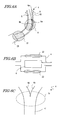
- FIGS. 6A , 6B , and 6C specific examples of the "region of the metal substrate surface that is to be heated to a temperature of about 350 °C or above", on which a chromium plating layer having a thickness of about 0.2 ⁇ m or more is to be formed according to preferred embodiments of the present invention, will be described.
- Each of these figures is a cross-sectional view showing a part of the exhaust pipe 4 .
- FIG. 6A shows an exhaust pipe congregation section 4a of the exhaust pipe 4 , which is directly connected to an engine.
- the exhaust pipe congregation section 4a which is connected to an engine (not shown), includes a metal tube 5 defining a passage 6 in which exhaust gas travels through; and a plating layer 10 covering the outer side surface of the metal tube 5 .
- the metal tube 5 includes a bent portion 9 .
- the bent portion 9 is a portion at which the passage 6 is bent, or a portion at which the longitudinal direction of the passage 6 changes.
- the plating layer 10 preferably includes an intermediate plating layer and a chromium plating layer.
- the metal tube 5 simply needs to define the passage 6 , and may have a double-tube structure composed of an inner tube defining the passage 6 and an outer tube covering the inner tube from the outside.
- the exhaust gas that comes through the exhaust pipe congregation section 4a which is directly connected to the engine (not shown), rapidly travels through the passage 6 , and therefore collides against the metal tube 5 at the bent portion 9 .
- the exhaust gas collides especially intensely against an inner side surface 9b of the metal tube 5 that is located at the convex surface portion 9a (which in itself is formed as a result of the bending). Therefore, the outer convex surface portion 9a is heated by the high-temperature exhaust gas to a temperature of about 350 °C or more (e.g., about 400 to 500°C).
- the metal tube 5 has a double-tube structure
- a single-tube structure is often adopted for a link section 21 at which another exhaust pipe member 23 is to be connected.
- the metal tube 5 might deform or be destroyed due to a difference in thermal expansion (between the outer tube and the inner tube) during the welding to the other exhaust pipe member 23 .
- the link section 21 will be heated to a temperature of about 350°C or more (e.g., about 400°C to about 500°C) as the high-temperature exhaust gas comes in direct contact with the inner side surface of the link section 21 .
- FIG. 6B schematically shows a cross section of a catalyst accommodating section 22 of the exhaust pipe 4, in which a catalytic apparatus 8 is accommodated.
- the catalytic apparatus 8 which is provided within the catalyst accommodating section 22 , decomposes at least one component contained in the exhaust gas when the exhaust gas travel therethrough. Since the catalytic apparatus 8 is heated responsive to the aforementioned decomposition, the catalyst accommodating section 22 is heated to a temperature of about 350°C or more (e.g., about 400°C to 500°C).
- the exhaust pipe 4 may include a manifold section for combining the exhaust gas generated in the respective cylinders so as to allow all such exhaust gas to be guided to the rear portion of the motorcycle 100.
- FIG. 6C shows an exhaust pipe 4 having a manifold section 15 at which branch pipes 4d and 4e (each of which is connected to a cylinder) come together, such that discharge takes place through a unified exhaust pipe member 4f .
- branch pipes 4d and 4e each of which is connected to a cylinder
- exhaust gas comes together through the plurality of branch pipes 4d and 4e , whereby the flow rate of the exhaust gas is increased, and the flow paths are deflected.
- the manifold section 15 is heated by the exhaust gas to a temperature of about 350°C or more (e.g., about 400°C to about 500°C).
- those portions of the exhaust pipe which are exemplified as being heated to a high temperature in FIGS. 6A , 6B , and 6C are preferably covered from the outside by a chromium plating layer of about 0.2 ⁇ m or more. As a result, even when exposed to a high-temperature exhaust gas, discoloration of the chromium plating layer due to the heating can be prevented.
- the present invention also encompasses a transportation apparatus incorporating the above-described engine part(s) according to other preferred embodiments of the present invention.
- transportation apparatus include a vehicle having an engine (e.g., a motorcycle or an all-climate four-wheeled vehicle) and a transportation apparatus having an engine (e.g., a marine vessel or an airplane).
- the method for producing an engine part according to a preferred embodiment of the present invention includes a step of placing a metal substrate in a plating apparatus, a step of coating the metal substrate with an intermediate plating layer, and a step of, by using a chromium plating bath, plating the metal substrate having the aforementioned intermediate plating layer formed thereon, in such a manner that a chromium plating layer of about 0.2 ⁇ m or more is formed in any region which is to be heated to a temperature of about 350°C or above.
- a metal substrate is immersed in a bath such as a water rinse bath, ultrasonic wave alkaline degreasing bath, electrolytic degreasing bath, or acid treatment activation bath for a predetermined period of time.
- a bath such as a water rinse bath, ultrasonic wave alkaline degreasing bath, electrolytic degreasing bath, or acid treatment activation bath for a predetermined period of time.
- Electroplating occurs based on the following principle.
- a material to be plated i.e., a material on which plating is to be formed
- a plating solution containing ions of a metal which will constitute the plating.
- the metal which will constitute the plating is also used as a soluble anode.
- a DC power source is connected between the electrodes and power is applied therefrom. As a result, ions of the metal which will constitute the plating are reduced at the cathode side, thus resulting in a metal deposit.
- Both the intermediate plating layer and the chromium plating layer are to be formed through electroplating, based on the same principle. Therefore, in the following description, only the step of forming the chromium plating layer will be described with specific reference to the plating apparatus shown in FIG. 7, whereas the step of forming the intermediate plating layer will be described without referring to any figures.
- the intermediate plating layer is formed by immersing the aforementioned metal substrate in a plating trough containing a solution of a metal which will constitute the plating, and applying power until reaching a desired thickness.
- a plating trough containing a solution of a metal which will constitute the plating
- power until reaching a desired thickness.
- three nickel plating layers namely a semigloss nickel plating layer, a tri-nickel plating layer, and a gloss nickel plating layer
- the metal substrate which has been washed in the aforementioned manner is immersed in a semigloss nickel plating bath, a tri-nickel plating bath, and a gloss nickel plating bath, and power is applied until the respective desired plating layers are obtained.
- the specific plating conditions will depend on the metal substrate to be used, plating bath composition, purpose, and the like.
- the conditions which are usually used for Ni-chromium plating can be selected as appropriate.
- a semigloss nickel plating layer about 5 ⁇ m to about 15 ⁇ m
- a tri-nickel plating layer about 1 ⁇ m to about 2 ⁇ m
- a gloss nickel plating layer about 5 ⁇ m to about 15 ⁇ m
- the plating time is preferably about 10 to 20 minutes for semigloss nickel plating as well as gloss nickel plating, and about 1 to 5 minutes for tri-nickel plating.
- a chromium plating apparatus 20 shown in FIG. 7 preferably includes a chromium plating trough 11 in which to perform chromium plating, a pump 12 for pumping up a plating solution which has been introduced to the chromium plating trough 11 , a percolator 13 for removing impurities which are suspended in the plating solution, an adjustment valve 14 for adjusting the flow rate of the plating solution, and a flowmeter 15 for monitoring the flow rate of the plating solution.
- an ion exchange apparatus 16 for removing the metal ions (such as Fe) contained in the plating solution is provided on the downstream end of the chromium plating apparatus 20 .
- the chromium plating apparatus 20 and the ion exchange apparatus 16 are connected to each other via a metal tube (not shown).
- a hexavalent chromium bath or a trivalent chromium bath is used for the chromium plating trough 11.
- a hexavalent chromium bath and a trivalent chromium bath differ mainly in terms of chromate type, and otherwise in terms of the types and amounts of other additives to be introduced to the baths. Since trivalent chromium is inferior to hexavalent chromium in terms of anticorrosiveness and contact with the base substrate, many additives are usually added to a trivalent chromium bath.
- a trivalent chromium bath includes not only basic chromium sulfate (Cr(OH)SO 4 ) having trivalent chromium ions (Cr 3+ ), but also a pH adjuster such as ammonium formate (HCOONH 4 ) or boric aid (H 3 BO 4 ). Furthermore, small amounts of additives such as a surfactant (e.g., sodium sulfosuccinate, sulfate-2-sodium ethylhexyl) and ferrous sulfate (FeSO 4 ⁇ 2H 2 O) are also added.
- a surfactant e.g., sodium sulfosuccinate, sulfate-2-sodium ethylhexyl
- FeSO 4 ⁇ 2H 2 O ferrous sulfate
- a hexavalent chromium bath generally includes not only chromic anhydride (CrO 3 ) containing hexavalent chromium ions (Cr 6+ ), but also an additive such as sulfuric acid (H 2 SO 4 ) or sodium silicofluoride (Na 2 SiF 6 ) .
- CrO 3 chromic anhydride
- Cr 6+ hexavalent chromium ions
- an additive such as sulfuric acid (H 2 SO 4 ) or sodium silicofluoride (Na 2 SiF 6 ) .
- ferrous sulfate and boric aid are not added to a hexavalent chromium bath.
- a chromium plating layer obtained by using hexavalent chromium contains substantially no Fe or B.
- the chromium plating is to be carried out via electroplating.
- a plating solution composing the aforementioned hexavalent chromium bath or trivalent chromium bath is added, and a metal substrate 17 which is to receive chromium plating is used as a cathode. Since chromium plating is to be performed while supplying chromium ions from the plating solution, an insoluble anode 18 which does not dissolve in a chromium plating solution is used as an anode.
- the DC power source 19 is connected between the electrodes, and power is supplied therefrom.
- the chromium ions contained in the chromium plating solution move toward the cathode side, i.e., the metal substrate 17 , where the ions are reduced to metal Cr and deposit.
- the plating is preferably performed while placing the metal substrate in a position which will allow a desired chromium plating layer to be obtained.
- a metal substrate such as a curved exhaust pipe
- a Cr layer can be efficiently formed at the convex portion 9a , which will be heated to a high temperature.
- the thickness of the chromium plating layer can be controlled to be within a predetermined range.
- the electrode positioning may be controlled, or an auxiliary electrode may be attached to control the current density or the like, for example, thus making it easier to form a predetermined chromium plating layer in regions which are to be heated to a temperature of about 350°C or above.
- appropriate conditions may be selected according to the type and shape of the metal substrate which is used, the constitution of the plating bath, the thickness of the chromium plating layer, or the like.
- the chromium plating layer After plating, the chromium plating layer has a surface roughness (Ra) of about 1 ⁇ m or less, and preferably has a surface roughness (Ra) of about 0.2 ⁇ m or less. Thus, the chromium plating layer has a sufficient brightness withough further sruface finishing process.
- a chromium plating layer is formed by using trivalent chromium
- a silver-gray color similar to that which is obtained by using hexavalent chromium can be obtained. Therefore, according to preferred embodiments of the present invention, no additive which contains Fe as a component (e.g., ferrous sulfate) is added to the trivalent chromium plating bath.
- various metal cations such as Fe ions and/or Cu ions may stray into the plating solution.
- Fe may be dissolved from the Fe substrate and diffuse into the chromium plating layer.
- Such dissolution of Fe is a phenomenon which is observed irrespective of the presence or absence of ferrous sulfate, and is particularly outstanding in the case where a thick chromium plating layer is formed, as in a preferred embodiment of the present invention.
- the Fe ions which stray into the plating solution are to be removed by using the ion exchange apparatus 16, which includes a cation exchange resin.
- the cation exchange resin to be used for preferred embodiments of the present invention may be any resin that permits easy exchange with divalent metal cations such as Fe, without any particular limitations.
- the specific removal method may be as follows. First, during the plating, the plating solution is regularly pumped up from the plating trough 11 by using the pump 12, and suspended matter is removed by using the percolator 13. Next, the plating solution from which the suspended matter has been removed is introduced into the ion exchange apparatus 16, while adjusting the flow rate via the adjustment valve 14 , and metal cations such as Fe ions are removed by using the cation exchange resin. The flow rate of the plating solution is monitored with the flowmeter 15 . The plating solution which has been processed by the ion exchange apparatus 16 is regularly collected in order to check for Fe concentration.
- the plating solution (recovered plating solution) from which Fe ions are thus removed exits the outlet of the ion exchange apparatus 16 , and is led through the tube path 24 , thus to be circulated to the plating trough 11 .
- the recovered plating solution may be stored in an appropriate storage container (not shown), for example.
- metal tubes composed of STKM were prepared, and a nickel plating layer composed of a semigloss nickel plating layer, a tri-nickel plating layer, and a gloss nickel plating layer was formed by the following method.
- the compositions of the plating baths used for forming these plating layers are shown in Table 1. Note that the C and/or S contained in the tri-nickel plating bath was supplied from an additive other than a brightener.
- Tri-nickel plating layer (thickness: about 1 ⁇ m to about 5 ⁇ m)
- Gloss nickel plating layer (thickness: about 5 ⁇ m to about 15 ⁇ m)
- a chromium plating layer was formed on the intermediate plating layer.
- a chromium plating bath As the chromium plating bath, a hexavalent chromium plating bath as described in Table 2, and two types of trivalent chromium plating baths as described in Table 3 were used.
- trivalent chromium plating baths described in Table 3 "present invention” is an example where no ferrous sulfate was added to the plating bath, whereas “conventional example” is an example where ferrous sulfate was contained in the plating bath.
- the thickness of the chromium plating layer was varied in the range from about 0.05 ⁇ m to about 1 ⁇ m, by changing the plating time in the range from about 5 to 20 minutes.
- the Fe ions which strayed into the plating were removed by using an ion exchange apparatus having a cation exchange resin. Specifically, a plating solution was regularly fed to the ion exchange apparatus, and the Fe concentration within the plating solution was controlled to be within the range from 0 to about 0.0001 mass%.
- the Fe concentration in the chromium plating layer of each sample thus obtained is shown in Table 4.
- each sample was placed in an atmospheric furnace, and after being heated under the conditions of approximately 500 °C ⁇ 8 hours, the degree of thermal discoloration and occurrence of cracks due to heating were measured by the following methods, and evaluated according to the following standards.
- Measurement method By using an optical microscope (magnification: x400), cracks occurring in the chromium plating layer surface (about 10mm ⁇ 10mm) were observed.
- a color tone similar to that which is obtained by using hexavalent chromium was obtained by reducing the Fe concentration in the chromium plating layer down to a predetermined range through the use of the trivalent chromium plating bath according to the example of preferred embodiments of the present invention.
- Such improvements in color tone were observed with respect to any chromium plating layer having a thickness in the range from about 0.1 ⁇ m to about 0.7 ⁇ m.
- FIGS. 9A and 9B indicate photographs of samples having chromium plating layers of different thicknesses, each photograph showing surface discoloration of the chromium plating after being heated at about 500°C for approximately 8 hours.
- the thickness of the chromium plating layer increases as follows, from left to right: 0.1 ⁇ m (comparative example); about 0.3 ⁇ m (present invention); and about 0.5 ⁇ m (present invention).
- FIG. 9A indicates photographs each showing a chromium plating layer with a reduced Fe content, obtained by using a trivalent chromium plating bath which contains no ferrous sulfate, the chromium plating layer having been heated.
- FIG. 9B indicates photographs each showing a chromium plating layer formed by using a conventional trivalent chromium plating bath which contains ferrous sulfate, the chromium plating layer having been heated. In either case, it can be clearly seen that, thermal discoloration due to heating is prevented by controlling the thickness of the chromium plating layer to be about 0.3 ⁇ m or more.
- thermal discoloration due to a high-temperature exhaust gas can be prevented by prescribing the thickness of a chromium plating layer to be about 0.3 ⁇ m or more, irrespective of the type of Cr used in the formation of the chromium plating layer. It has also been confirmed that, in the case of forming a chromium plating layer by using trivalent chromium, a color tone similar to that which is obtained by using hexavalent chromium can be obtained by reducing the Fe concentration in the chromium plating layer.
- the present invention is broadly applicable to a vehicle having an engine (e.g., a motorcycle or an all-terrain four-wheeled vehicle) and a transportation apparatus having an engine (e.g., a ship or an airplane).
- a vehicle having an engine e.g., a motorcycle or an all-terrain four-wheeled vehicle
- a transportation apparatus having an engine (e.g., a ship or an airplane).
Landscapes
- Chemical & Material Sciences (AREA)
- Engineering & Computer Science (AREA)
- Chemical Kinetics & Catalysis (AREA)
- Electrochemistry (AREA)
- Materials Engineering (AREA)
- Metallurgy (AREA)
- Organic Chemistry (AREA)
- Crystallography & Structural Chemistry (AREA)
- Combustion & Propulsion (AREA)
- Mechanical Engineering (AREA)
- General Engineering & Computer Science (AREA)
- Exhaust Silencers (AREA)
- Electroplating Methods And Accessories (AREA)
- Other Surface Treatments For Metallic Materials (AREA)
Applications Claiming Priority (1)
| Application Number | Priority Date | Filing Date | Title |
|---|---|---|---|
| JP2004230439 | 2004-08-06 |
Publications (1)
| Publication Number | Publication Date |
|---|---|
| EP1624092A1 true EP1624092A1 (de) | 2006-02-08 |
Family
ID=35219280
Family Applications (1)
| Application Number | Title | Priority Date | Filing Date |
|---|---|---|---|
| EP05017075A Withdrawn EP1624092A1 (de) | 2004-08-06 | 2005-08-05 | Verchromtes Auspuff |
Country Status (2)
| Country | Link |
|---|---|
| US (2) | US7726121B2 (de) |
| EP (1) | EP1624092A1 (de) |
Cited By (2)
| Publication number | Priority date | Publication date | Assignee | Title |
|---|---|---|---|---|
| DE102007052800B3 (de) * | 2007-11-02 | 2009-05-07 | Märkisches Werk GmbH | Ein- oder Auslassventil für einen Verbrennungsmotor sowie Verfahren zu dessen Herstellung |
| DE102019129128A1 (de) * | 2019-10-29 | 2021-04-29 | Federal-Mogul Valvetrain Gmbh | Motorventil |
Families Citing this family (4)
| Publication number | Priority date | Publication date | Assignee | Title |
|---|---|---|---|---|
| EP1845176A4 (de) * | 2004-10-18 | 2011-06-29 | Yamaha Motor Co Ltd | Motorteil |
| JP2009074168A (ja) * | 2007-08-30 | 2009-04-09 | Nissan Motor Co Ltd | クロムめっき部品およびその製造方法 |
| JP5771133B2 (ja) * | 2011-11-30 | 2015-08-26 | 株式会社クボタ | 作業車の排気装置 |
| FR3025809B1 (fr) * | 2014-09-12 | 2016-09-30 | Herakles | Procede de controle d'une piece par colorimetrie |
Citations (12)
| Publication number | Priority date | Publication date | Assignee | Title |
|---|---|---|---|---|
| DE926580C (de) | 1952-05-07 | 1955-04-21 | Hans Dipl-Ing Beck | Verfahren zur galvanischen Erzeugung von mit Kupfer-, Nickel- und Chromschichten ueberzogenen Blechen oder Baendern |
| US3009238A (en) * | 1957-12-03 | 1961-11-21 | Int Nickel Co | Protective and decorative nickel coatings |
| FR1284763A (fr) | 1960-02-29 | 1962-02-16 | Harshaw Chem Corp | Revêtement d'objets métalliques, résistant à la corrosion |
| FR1350959A (fr) * | 1962-02-23 | 1964-01-31 | Res Holland Nv | Procédé pour recouvrir par galvanoplastie la surface d'objets avec des revêtements protecteurs et décoratifs de nickel brillant-chrome et objets obtenus par ce procédé |
| US3404750A (en) | 1966-07-14 | 1968-10-08 | Walker Mfg Co | Combination tailpipe spout and silencer |
| DE1496930A1 (de) | 1964-01-11 | 1969-12-18 | Res Holland Nv | Verfahren zum Aufbringen von korrosionsbestaendigen und verschleissbestaendigen Schichten |
| EP0147484A1 (de) * | 1983-12-30 | 1985-07-10 | INDUSTRIALE S.r.l. | Verfahren zur Herstellung einer Schutzschicht für Oberflächen die mechanischem und thermischem Verschleiss unterworfen sind |
| FR2583070A1 (fr) | 1985-06-11 | 1986-12-12 | Limburgs Galvano Tech Bedri | Procede de protection contre l'usure et la corrosion de pieces en acier, en particulier de cylindres hydrauliques |
| GB2188942A (en) | 1986-04-11 | 1987-10-14 | Rolls Royce Plc | Protective coating |
| DE3934112A1 (de) * | 1988-10-29 | 1990-05-03 | Usui Kokusai Sangyo Kk | Stahlerzeugnis mit waermebestaendigen, korrosionsbestaendigen ueberzugsschichten |
| DE19542313A1 (de) * | 1994-11-14 | 1996-06-05 | Usui Kokusai Sangyo Kk | Hitzebeständiges und korrosionsfestes, lamellares, metallplattiertes Stahlmaterial mit gleichmäßiger Verarbeitbarkeit und Korrosionsschutz |
| EP1010777A2 (de) * | 1998-12-01 | 2000-06-21 | Masco Corporation Of Indiana | Gegenstand überzogen mit Mehrschichtüberzügen |
Family Cites Families (21)
| Publication number | Priority date | Publication date | Assignee | Title |
|---|---|---|---|---|
| US2232395A (en) * | 1936-09-08 | 1941-02-18 | Jr Louis A Koch | Automobile exhaust shroud |
| US2449756A (en) | 1947-02-18 | 1948-09-21 | Cal Pan Corp | Tail pipe extension |
| CH308578A (de) * | 1952-07-28 | 1955-07-31 | Bbc Brown Boveri & Cie | Gasturbinenbauteil aus Chromstahl mit einer keramischen Schutzschicht. |
| US3488723A (en) * | 1966-07-05 | 1970-01-06 | Owens Corning Fiberglass Corp | Acoustical material for high temperature application |
| US3500954A (en) * | 1969-03-13 | 1970-03-17 | Walker Mfg Co | Exhaust silencing system |
| DE3276912D1 (en) * | 1981-11-05 | 1987-09-10 | Mitsubishi Electric Corp | Exhaust silencer for internal combustion engine |
| JPS58207375A (ja) * | 1982-05-28 | 1983-12-02 | Usui Internatl Ind Co Ltd | 耐熱・耐食性被覆金属管及びその製造方法 |
| JPS61177238A (ja) * | 1985-02-02 | 1986-08-08 | 日新製鋼株式会社 | マフラ−用塗装鋼板およびその製造方法 |
| US5246786A (en) | 1988-10-29 | 1993-09-21 | Usui Kokusai Sangyo Kaisha Ltd. | Steel product with heat-resistant, corrosion-resistant plating layers |
| AU638121B2 (en) | 1990-04-30 | 1993-06-17 | Atochem North America, Inc. | Apparatus and process to regenerate a trivalent chromium bath |
| US5269905A (en) | 1990-04-30 | 1993-12-14 | Elf Atochem North America, Inc. | Apparatus and process to regenerate a trivalent chromium bath |
| JPH09228069A (ja) | 1996-02-21 | 1997-09-02 | Nippon Denko Kk | クロムめっき液またはクロメート液の精製方法および装置 |
| US5783622A (en) * | 1997-05-05 | 1998-07-21 | Armco Inc. | Precoated chromium alloyed steel with enhanced paint adhesion for exhaust applications |
| JP3885375B2 (ja) * | 1997-09-30 | 2007-02-21 | 帝国ピストンリング株式会社 | ピストンリング |
| JP2000328939A (ja) | 1999-05-21 | 2000-11-28 | Suzuki Motor Corp | 自動2輪車の排気消音装置 |
| JP2003013752A (ja) | 2001-07-02 | 2003-01-15 | Knorr-Bremse Commercial Vehicle Systems Japan Ltd | 排気管開閉弁装置 |
| JP2003041933A (ja) | 2001-07-26 | 2003-02-13 | Suzuki Motor Corp | 排気装置 |
| JP2003254096A (ja) | 2001-12-26 | 2003-09-10 | Nippon Piston Ring Co Ltd | 排気ブレーキ装置 |
| JP2003254095A (ja) | 2001-12-26 | 2003-09-10 | Nippon Piston Ring Co Ltd | 排気ブレーキ装置 |
| JP2003232219A (ja) | 2002-02-08 | 2003-08-22 | Aisan Ind Co Ltd | 排気管 |
| JP2003277976A (ja) | 2002-03-26 | 2003-10-02 | Osaka Gas Co Ltd | 耐熱部材およびその製造方法 |
-
2005
- 2005-08-04 US US11/197,631 patent/US7726121B2/en not_active Expired - Fee Related
- 2005-08-05 EP EP05017075A patent/EP1624092A1/de not_active Withdrawn
-
2010
- 2010-04-08 US US12/756,326 patent/US20100192554A1/en not_active Abandoned
Patent Citations (12)
| Publication number | Priority date | Publication date | Assignee | Title |
|---|---|---|---|---|
| DE926580C (de) | 1952-05-07 | 1955-04-21 | Hans Dipl-Ing Beck | Verfahren zur galvanischen Erzeugung von mit Kupfer-, Nickel- und Chromschichten ueberzogenen Blechen oder Baendern |
| US3009238A (en) * | 1957-12-03 | 1961-11-21 | Int Nickel Co | Protective and decorative nickel coatings |
| FR1284763A (fr) | 1960-02-29 | 1962-02-16 | Harshaw Chem Corp | Revêtement d'objets métalliques, résistant à la corrosion |
| FR1350959A (fr) * | 1962-02-23 | 1964-01-31 | Res Holland Nv | Procédé pour recouvrir par galvanoplastie la surface d'objets avec des revêtements protecteurs et décoratifs de nickel brillant-chrome et objets obtenus par ce procédé |
| DE1496930A1 (de) | 1964-01-11 | 1969-12-18 | Res Holland Nv | Verfahren zum Aufbringen von korrosionsbestaendigen und verschleissbestaendigen Schichten |
| US3404750A (en) | 1966-07-14 | 1968-10-08 | Walker Mfg Co | Combination tailpipe spout and silencer |
| EP0147484A1 (de) * | 1983-12-30 | 1985-07-10 | INDUSTRIALE S.r.l. | Verfahren zur Herstellung einer Schutzschicht für Oberflächen die mechanischem und thermischem Verschleiss unterworfen sind |
| FR2583070A1 (fr) | 1985-06-11 | 1986-12-12 | Limburgs Galvano Tech Bedri | Procede de protection contre l'usure et la corrosion de pieces en acier, en particulier de cylindres hydrauliques |
| GB2188942A (en) | 1986-04-11 | 1987-10-14 | Rolls Royce Plc | Protective coating |
| DE3934112A1 (de) * | 1988-10-29 | 1990-05-03 | Usui Kokusai Sangyo Kk | Stahlerzeugnis mit waermebestaendigen, korrosionsbestaendigen ueberzugsschichten |
| DE19542313A1 (de) * | 1994-11-14 | 1996-06-05 | Usui Kokusai Sangyo Kk | Hitzebeständiges und korrosionsfestes, lamellares, metallplattiertes Stahlmaterial mit gleichmäßiger Verarbeitbarkeit und Korrosionsschutz |
| EP1010777A2 (de) * | 1998-12-01 | 2000-06-21 | Masco Corporation Of Indiana | Gegenstand überzogen mit Mehrschichtüberzügen |
Cited By (2)
| Publication number | Priority date | Publication date | Assignee | Title |
|---|---|---|---|---|
| DE102007052800B3 (de) * | 2007-11-02 | 2009-05-07 | Märkisches Werk GmbH | Ein- oder Auslassventil für einen Verbrennungsmotor sowie Verfahren zu dessen Herstellung |
| DE102019129128A1 (de) * | 2019-10-29 | 2021-04-29 | Federal-Mogul Valvetrain Gmbh | Motorventil |
Also Published As
| Publication number | Publication date |
|---|---|
| US20060026952A1 (en) | 2006-02-09 |
| US7726121B2 (en) | 2010-06-01 |
| US20100192554A1 (en) | 2010-08-05 |
Similar Documents
| Publication | Publication Date | Title |
|---|---|---|
| EP1845176A1 (de) | Motorteil | |
| US20100192554A1 (en) | Engine part | |
| EP1446262B9 (de) | Flussmittelfreies hartlöten | |
| EP2746422B1 (de) | Aluminiumplattiertes stahlblech mit hervorragender korrosionsbeständigkeit gegenüber alkohol oder eines benzingemisches damit und hervorragendes erscheinungsbild und verfahren zu herstellung desselben | |
| JP4571546B2 (ja) | 耐摩耗性部材および動力伝達部品 | |
| EP1184478B1 (de) | Oberflächenbehandeltes stahlprodukt versehen mit einer auf zinn oder aluminium basierenden plattierung | |
| US20040035910A1 (en) | Low temperature fluxless brazing | |
| EP2455509B1 (de) | Feuerverzinktes al-zn-plattiertes stahlblech | |
| JP2006070894A (ja) | エンジン用部品 | |
| JPH10287986A (ja) | 密着性に優れたMg合金部材およびその製造方法 | |
| US20040035911A1 (en) | Fluxless brazing | |
| EP0866149A2 (de) | Mit einer zinkhaltigen Schicht versehenes Stahlblech und Verfahren zu seiner Herstellung | |
| US5849423A (en) | Zinciferous plated steel sheet and method for manufacturing same | |
| JPS60138093A (ja) | 高耐食性表面処理鋼板 | |
| CA1242987A (en) | Process for preparing improved zn-ni-alloy electroplated steel sheets | |
| JPH11152555A (ja) | 耐食性、溶接性に優れた燃料タンク用防錆鋼板 | |
| EP0751240A1 (de) | Oberflächenbehandelte stahlplatte für brennstofftanks | |
| AU638630B2 (en) | Plated aluminum sheet having improved spot weldability | |
| JPS631393B2 (de) | ||
| JP3444179B2 (ja) | 加工性、化成処理性、スポット溶接性に優れた合金化溶融亜鉛めっき鋼板とその製造方法 | |
| TWI690604B (zh) | 熔融Sn-Zn系合金鍍敷鋼板及其製造方法 | |
| KR890002496B1 (ko) | 내식성이 우수한 아연-니켈 합금의 전기도금 강판 제조법 | |
| Funatani et al. | Surface modification | |
| JP3242171B2 (ja) | 電着塗装仕上がり性に優れた複層めっき鋼板及びその製造方法 | |
| JP2587721B2 (ja) | 亜鉛系メッキアルミニウム板の製造方法 |
Legal Events
| Date | Code | Title | Description |
|---|---|---|---|
| PUAI | Public reference made under article 153(3) epc to a published international application that has entered the european phase |
Free format text: ORIGINAL CODE: 0009012 |
|
| AK | Designated contracting states |
Kind code of ref document: A1 Designated state(s): AT BE BG CH CY CZ DE DK EE ES FI FR GB GR HU IE IS IT LI LT LU LV MC NL PL PT RO SE SI SK TR |
|
| AX | Request for extension of the european patent |
Extension state: AL BA HR MK YU |
|
| 17P | Request for examination filed |
Effective date: 20060328 |
|
| AKX | Designation fees paid |
Designated state(s): AT BE BG CH CY CZ DE DK EE ES FI FR GB GR HU IE IS IT LI LT LU LV MC NL PL PT RO SE SI SK TR |
|
| GRAP | Despatch of communication of intention to grant a patent |
Free format text: ORIGINAL CODE: EPIDOSNIGR1 |
|
| RIC1 | Information provided on ipc code assigned before grant |
Ipc: F01N 13/16 20100101ALI20120109BHEP Ipc: B60K 13/04 20060101ALI20120109BHEP Ipc: C25D 7/04 20060101ALI20120109BHEP Ipc: C25D 5/14 20060101ALI20120109BHEP Ipc: C25D 5/12 20060101AFI20120109BHEP |
|
| STAA | Information on the status of an ep patent application or granted ep patent |
Free format text: STATUS: THE APPLICATION IS DEEMED TO BE WITHDRAWN |
|
| 18D | Application deemed to be withdrawn |
Effective date: 20120627 |