EP1620635B1 - Systeme et methodes pour une commande d'emission amelioree de moteurs a combustion interne faisant appel a un ecoulement de combustible pulse - Google Patents
Systeme et methodes pour une commande d'emission amelioree de moteurs a combustion interne faisant appel a un ecoulement de combustible pulse Download PDFInfo
- Publication number
- EP1620635B1 EP1620635B1 EP04751403A EP04751403A EP1620635B1 EP 1620635 B1 EP1620635 B1 EP 1620635B1 EP 04751403 A EP04751403 A EP 04751403A EP 04751403 A EP04751403 A EP 04751403A EP 1620635 B1 EP1620635 B1 EP 1620635B1
- Authority
- EP
- European Patent Office
- Prior art keywords
- fuel
- catalyst
- fuel processor
- processor
- nsr
- Prior art date
- Legal status (The legal status is an assumption and is not a legal conclusion. Google has not performed a legal analysis and makes no representation as to the accuracy of the status listed.)
- Expired - Lifetime
Links
- 239000000446 fuel Substances 0.000 title claims abstract description 415
- 238000000034 method Methods 0.000 title claims abstract description 31
- 238000002485 combustion reaction Methods 0.000 title abstract description 15
- 239000003054 catalyst Substances 0.000 claims abstract description 324
- 239000000203 mixture Substances 0.000 claims abstract description 69
- 239000007789 gas Substances 0.000 claims abstract description 60
- 229910002091 carbon monoxide Inorganic materials 0.000 claims abstract description 46
- 239000001301 oxygen Substances 0.000 claims abstract description 45
- 229910052760 oxygen Inorganic materials 0.000 claims abstract description 45
- QVGXLLKOCUKJST-UHFFFAOYSA-N atomic oxygen Chemical compound [O] QVGXLLKOCUKJST-UHFFFAOYSA-N 0.000 claims abstract description 44
- 238000002347 injection Methods 0.000 claims abstract description 33
- 239000007924 injection Substances 0.000 claims abstract description 33
- 238000002407 reforming Methods 0.000 claims abstract description 33
- 230000003647 oxidation Effects 0.000 claims abstract description 31
- 238000007254 oxidation reaction Methods 0.000 claims abstract description 31
- 230000008929 regeneration Effects 0.000 claims abstract description 28
- 238000011069 regeneration method Methods 0.000 claims abstract description 28
- 238000011144 upstream manufacturing Methods 0.000 claims abstract description 27
- 239000003463 adsorbent Substances 0.000 claims abstract description 20
- 239000000463 material Substances 0.000 claims description 18
- NINIDFKCEFEMDL-UHFFFAOYSA-N Sulfur Chemical compound [S] NINIDFKCEFEMDL-UHFFFAOYSA-N 0.000 claims description 16
- 229910052717 sulfur Inorganic materials 0.000 claims description 16
- 239000011593 sulfur Substances 0.000 claims description 16
- 239000002283 diesel fuel Substances 0.000 claims description 13
- 229910052703 rhodium Inorganic materials 0.000 claims description 11
- 229930195733 hydrocarbon Natural products 0.000 claims description 10
- 150000002430 hydrocarbons Chemical class 0.000 claims description 10
- 229910052751 metal Inorganic materials 0.000 claims description 10
- 239000002184 metal Substances 0.000 claims description 10
- 230000001590 oxidative effect Effects 0.000 claims description 9
- 229910052763 palladium Inorganic materials 0.000 claims description 8
- 229910052697 platinum Inorganic materials 0.000 claims description 8
- 230000003068 static effect Effects 0.000 claims description 6
- 239000002966 varnish Substances 0.000 claims description 6
- 239000004215 Carbon black (E152) Substances 0.000 claims description 4
- 229910052741 iridium Inorganic materials 0.000 claims description 4
- 239000006200 vaporizer Substances 0.000 claims description 4
- 239000000919 ceramic Substances 0.000 claims description 3
- 229910052742 iron Inorganic materials 0.000 claims description 3
- 229910052759 nickel Inorganic materials 0.000 claims description 3
- 230000000737 periodic effect Effects 0.000 claims description 3
- 230000001172 regenerating effect Effects 0.000 claims description 3
- 229910052804 chromium Inorganic materials 0.000 claims description 2
- 229910052802 copper Inorganic materials 0.000 claims description 2
- 229910052750 molybdenum Inorganic materials 0.000 claims description 2
- 239000005864 Sulphur Substances 0.000 claims 1
- 230000006835 compression Effects 0.000 claims 1
- 238000007906 compression Methods 0.000 claims 1
- IJGRMHOSHXDMSA-UHFFFAOYSA-N Atomic nitrogen Chemical compound N#N IJGRMHOSHXDMSA-UHFFFAOYSA-N 0.000 abstract description 16
- 238000006243 chemical reaction Methods 0.000 abstract description 10
- 229910052757 nitrogen Inorganic materials 0.000 abstract description 8
- 238000011217 control strategy Methods 0.000 abstract description 7
- MWUXSHHQAYIFBG-UHFFFAOYSA-N nitrogen oxide Inorganic materials O=[N] MWUXSHHQAYIFBG-UHFFFAOYSA-N 0.000 abstract description 6
- 230000036961 partial effect Effects 0.000 abstract description 2
- UGFAIRIUMAVXCW-UHFFFAOYSA-N Carbon monoxide Chemical compound [O+]#[C-] UGFAIRIUMAVXCW-UHFFFAOYSA-N 0.000 description 45
- 239000003570 air Substances 0.000 description 26
- XLYOFNOQVPJJNP-UHFFFAOYSA-N water Chemical compound O XLYOFNOQVPJJNP-UHFFFAOYSA-N 0.000 description 19
- 229910001868 water Inorganic materials 0.000 description 18
- 239000010948 rhodium Substances 0.000 description 16
- CURLTUGMZLYLDI-UHFFFAOYSA-N Carbon dioxide Chemical compound O=C=O CURLTUGMZLYLDI-UHFFFAOYSA-N 0.000 description 15
- 239000003638 chemical reducing agent Substances 0.000 description 14
- 238000005516 engineering process Methods 0.000 description 14
- 229910002092 carbon dioxide Inorganic materials 0.000 description 13
- MCMNRKCIXSYSNV-UHFFFAOYSA-N Zirconium dioxide Chemical compound O=[Zr]=O MCMNRKCIXSYSNV-UHFFFAOYSA-N 0.000 description 12
- 238000001179 sorption measurement Methods 0.000 description 12
- 238000012360 testing method Methods 0.000 description 9
- 230000008901 benefit Effects 0.000 description 8
- 238000013461 design Methods 0.000 description 8
- 230000009467 reduction Effects 0.000 description 8
- 230000003247 decreasing effect Effects 0.000 description 7
- 230000008569 process Effects 0.000 description 7
- 239000003502 gasoline Substances 0.000 description 6
- 239000007788 liquid Substances 0.000 description 6
- 238000002156 mixing Methods 0.000 description 6
- 230000002829 reductive effect Effects 0.000 description 6
- 239000011888 foil Substances 0.000 description 5
- 229910052734 helium Inorganic materials 0.000 description 5
- 238000011068 loading method Methods 0.000 description 5
- 239000000758 substrate Substances 0.000 description 5
- PNEYBMLMFCGWSK-UHFFFAOYSA-N aluminium oxide Inorganic materials [O-2].[O-2].[O-2].[Al+3].[Al+3] PNEYBMLMFCGWSK-UHFFFAOYSA-N 0.000 description 4
- 230000033228 biological regulation Effects 0.000 description 4
- 230000003197 catalytic effect Effects 0.000 description 4
- 239000011248 coating agent Substances 0.000 description 4
- 238000000576 coating method Methods 0.000 description 4
- 230000000694 effects Effects 0.000 description 4
- 239000001257 hydrogen Substances 0.000 description 4
- 229910052739 hydrogen Inorganic materials 0.000 description 4
- 238000013021 overheating Methods 0.000 description 4
- RVTZCBVAJQQJTK-UHFFFAOYSA-N oxygen(2-);zirconium(4+) Chemical compound [O-2].[O-2].[Zr+4] RVTZCBVAJQQJTK-UHFFFAOYSA-N 0.000 description 4
- 239000000243 solution Substances 0.000 description 4
- 229910052815 sulfur oxide Inorganic materials 0.000 description 4
- 150000003467 sulfuric acid derivatives Chemical class 0.000 description 4
- 229910001928 zirconium oxide Inorganic materials 0.000 description 4
- VYPSYNLAJGMNEJ-UHFFFAOYSA-N Silicium dioxide Chemical compound O=[Si]=O VYPSYNLAJGMNEJ-UHFFFAOYSA-N 0.000 description 3
- 238000013459 approach Methods 0.000 description 3
- 230000009849 deactivation Effects 0.000 description 3
- WDNQRCVBPNOTNV-UHFFFAOYSA-N dinonylnaphthylsulfonic acid Chemical compound C1=CC=C2C(S(O)(=O)=O)=C(CCCCCCCCC)C(CCCCCCCCC)=CC2=C1 WDNQRCVBPNOTNV-UHFFFAOYSA-N 0.000 description 3
- 238000012545 processing Methods 0.000 description 3
- 238000000197 pyrolysis Methods 0.000 description 3
- MHOVAHRLVXNVSD-UHFFFAOYSA-N rhodium atom Chemical compound [Rh] MHOVAHRLVXNVSD-UHFFFAOYSA-N 0.000 description 3
- 239000002002 slurry Substances 0.000 description 3
- 239000007787 solid Substances 0.000 description 3
- 239000004071 soot Substances 0.000 description 3
- 241000894007 species Species 0.000 description 3
- XTQHKBHJIVJGKJ-UHFFFAOYSA-N sulfur monoxide Chemical class S=O XTQHKBHJIVJGKJ-UHFFFAOYSA-N 0.000 description 3
- QGZKDVFQNNGYKY-UHFFFAOYSA-N Ammonia Chemical compound N QGZKDVFQNNGYKY-UHFFFAOYSA-N 0.000 description 2
- OKTJSMMVPCPJKN-UHFFFAOYSA-N Carbon Chemical compound [C] OKTJSMMVPCPJKN-UHFFFAOYSA-N 0.000 description 2
- UFHFLCQGNIYNRP-UHFFFAOYSA-N Hydrogen Chemical compound [H][H] UFHFLCQGNIYNRP-UHFFFAOYSA-N 0.000 description 2
- 229910021604 Rhodium(III) chloride Inorganic materials 0.000 description 2
- GWEVSGVZZGPLCZ-UHFFFAOYSA-N Titan oxide Chemical compound O=[Ti]=O GWEVSGVZZGPLCZ-UHFFFAOYSA-N 0.000 description 2
- 229910000287 alkaline earth metal oxide Inorganic materials 0.000 description 2
- QVQLCTNNEUAWMS-UHFFFAOYSA-N barium oxide Chemical compound [Ba]=O QVQLCTNNEUAWMS-UHFFFAOYSA-N 0.000 description 2
- 239000011324 bead Substances 0.000 description 2
- 229910052799 carbon Inorganic materials 0.000 description 2
- 239000001569 carbon dioxide Substances 0.000 description 2
- 238000006555 catalytic reaction Methods 0.000 description 2
- 238000004140 cleaning Methods 0.000 description 2
- 230000007613 environmental effect Effects 0.000 description 2
- 230000014509 gene expression Effects 0.000 description 2
- 150000002431 hydrogen Chemical class 0.000 description 2
- 230000006872 improvement Effects 0.000 description 2
- 238000011017 operating method Methods 0.000 description 2
- TWNQGVIAIRXVLR-UHFFFAOYSA-N oxo(oxoalumanyloxy)alumane Chemical compound O=[Al]O[Al]=O TWNQGVIAIRXVLR-UHFFFAOYSA-N 0.000 description 2
- 239000008188 pellet Substances 0.000 description 2
- 239000000843 powder Substances 0.000 description 2
- SONJTKJMTWTJCT-UHFFFAOYSA-K rhodium(iii) chloride Chemical compound [Cl-].[Cl-].[Cl-].[Rh+3] SONJTKJMTWTJCT-UHFFFAOYSA-K 0.000 description 2
- 229920006395 saturated elastomer Polymers 0.000 description 2
- 238000003756 stirring Methods 0.000 description 2
- 238000012546 transfer Methods 0.000 description 2
- 238000009834 vaporization Methods 0.000 description 2
- 230000008016 vaporization Effects 0.000 description 2
- VHUUQVKOLVNVRT-UHFFFAOYSA-N Ammonium hydroxide Chemical compound [NH4+].[OH-] VHUUQVKOLVNVRT-UHFFFAOYSA-N 0.000 description 1
- 241000046053 Betta Species 0.000 description 1
- 241000220317 Rosa Species 0.000 description 1
- QAOWNCQODCNURD-UHFFFAOYSA-L Sulfate Chemical compound [O-]S([O-])(=O)=O QAOWNCQODCNURD-UHFFFAOYSA-L 0.000 description 1
- XSQUKJJJFZCRTK-UHFFFAOYSA-N Urea Chemical compound NC(N)=O XSQUKJJJFZCRTK-UHFFFAOYSA-N 0.000 description 1
- QCWXUUIWCKQGHC-UHFFFAOYSA-N Zirconium Chemical compound [Zr] QCWXUUIWCKQGHC-UHFFFAOYSA-N 0.000 description 1
- 238000005299 abrasion Methods 0.000 description 1
- 239000000654 additive Substances 0.000 description 1
- 230000002411 adverse Effects 0.000 description 1
- 150000001298 alcohols Chemical class 0.000 description 1
- 239000003513 alkali Substances 0.000 description 1
- 229910021529 ammonia Inorganic materials 0.000 description 1
- 239000000908 ammonium hydroxide Substances 0.000 description 1
- 229910052788 barium Inorganic materials 0.000 description 1
- 238000009529 body temperature measurement Methods 0.000 description 1
- 229910052791 calcium Inorganic materials 0.000 description 1
- 239000011575 calcium Substances 0.000 description 1
- BRPQOXSCLDDYGP-UHFFFAOYSA-N calcium oxide Chemical compound [O-2].[Ca+2] BRPQOXSCLDDYGP-UHFFFAOYSA-N 0.000 description 1
- 239000000292 calcium oxide Substances 0.000 description 1
- ODINCKMPIJJUCX-UHFFFAOYSA-N calcium oxide Inorganic materials [Ca]=O ODINCKMPIJJUCX-UHFFFAOYSA-N 0.000 description 1
- 239000004202 carbamide Substances 0.000 description 1
- 230000015556 catabolic process Effects 0.000 description 1
- 239000003795 chemical substances by application Substances 0.000 description 1
- 238000005229 chemical vapour deposition Methods 0.000 description 1
- 238000005094 computer simulation Methods 0.000 description 1
- 238000001816 cooling Methods 0.000 description 1
- 125000004122 cyclic group Chemical group 0.000 description 1
- 238000000354 decomposition reaction Methods 0.000 description 1
- 238000006731 degradation reaction Methods 0.000 description 1
- 239000008367 deionised water Substances 0.000 description 1
- 229910021641 deionized water Inorganic materials 0.000 description 1
- 230000001419 dependent effect Effects 0.000 description 1
- 238000000151 deposition Methods 0.000 description 1
- 230000008021 deposition Effects 0.000 description 1
- 238000007598 dipping method Methods 0.000 description 1
- 230000009977 dual effect Effects 0.000 description 1
- 238000007772 electroless plating Methods 0.000 description 1
- 238000009713 electroplating Methods 0.000 description 1
- 238000005265 energy consumption Methods 0.000 description 1
- 238000011156 evaluation Methods 0.000 description 1
- 238000010285 flame spraying Methods 0.000 description 1
- 230000004907 flux Effects 0.000 description 1
- 239000005431 greenhouse gas Substances 0.000 description 1
- 238000010438 heat treatment Methods 0.000 description 1
- 239000001307 helium Substances 0.000 description 1
- SWQJXJOGLNCZEY-UHFFFAOYSA-N helium atom Chemical compound [He] SWQJXJOGLNCZEY-UHFFFAOYSA-N 0.000 description 1
- 238000010348 incorporation Methods 0.000 description 1
- 230000000670 limiting effect Effects 0.000 description 1
- 238000004519 manufacturing process Methods 0.000 description 1
- 238000007620 mathematical function Methods 0.000 description 1
- 238000005259 measurement Methods 0.000 description 1
- 150000002739 metals Chemical class 0.000 description 1
- VUZPPFZMUPKLLV-UHFFFAOYSA-N methane;hydrate Chemical compound C.O VUZPPFZMUPKLLV-UHFFFAOYSA-N 0.000 description 1
- 238000012986 modification Methods 0.000 description 1
- 230000004048 modification Effects 0.000 description 1
- QWDUNBOWGVRUCG-UHFFFAOYSA-N n-(4-chloro-2-nitrophenyl)acetamide Chemical compound CC(=O)NC1=CC=C(Cl)C=C1[N+]([O-])=O QWDUNBOWGVRUCG-UHFFFAOYSA-N 0.000 description 1
- 150000002926 oxygen Chemical class 0.000 description 1
- 239000002245 particle Substances 0.000 description 1
- 239000013618 particulate matter Substances 0.000 description 1
- 239000003208 petroleum Substances 0.000 description 1
- 239000002574 poison Substances 0.000 description 1
- 231100000614 poison Toxicity 0.000 description 1
- 238000002360 preparation method Methods 0.000 description 1
- QQONPFPTGQHPMA-UHFFFAOYSA-N propylene Natural products CC=C QQONPFPTGQHPMA-UHFFFAOYSA-N 0.000 description 1
- 125000004805 propylene group Chemical group [H]C([H])([H])C([H])([*:1])C([H])([H])[*:2] 0.000 description 1
- -1 propylene) Chemical class 0.000 description 1
- 239000000700 radioactive tracer Substances 0.000 description 1
- 229910001404 rare earth metal oxide Inorganic materials 0.000 description 1
- 230000004044 response Effects 0.000 description 1
- 230000002441 reversible effect Effects 0.000 description 1
- 230000000630 rising effect Effects 0.000 description 1
- 239000000523 sample Substances 0.000 description 1
- 238000005070 sampling Methods 0.000 description 1
- 229910052710 silicon Inorganic materials 0.000 description 1
- 239000000377 silicon dioxide Substances 0.000 description 1
- 229910052814 silicon oxide Inorganic materials 0.000 description 1
- 239000006104 solid solution Substances 0.000 description 1
- 238000001228 spectrum Methods 0.000 description 1
- 239000007921 spray Substances 0.000 description 1
- 238000004230 steam cracking Methods 0.000 description 1
- 238000003860 storage Methods 0.000 description 1
- 150000003463 sulfur Chemical class 0.000 description 1
- 239000000725 suspension Substances 0.000 description 1
- 238000005303 weighing Methods 0.000 description 1
- 229910052726 zirconium Inorganic materials 0.000 description 1
Images

Classifications
-
- C—CHEMISTRY; METALLURGY
- C01—INORGANIC CHEMISTRY
- C01B—NON-METALLIC ELEMENTS; COMPOUNDS THEREOF; METALLOIDS OR COMPOUNDS THEREOF NOT COVERED BY SUBCLASS C01C
- C01B3/00—Hydrogen; Gaseous mixtures containing hydrogen; Separation of hydrogen from mixtures containing it; Purification of hydrogen
- C01B3/02—Production of hydrogen or of gaseous mixtures containing a substantial proportion of hydrogen
- C01B3/32—Production of hydrogen or of gaseous mixtures containing a substantial proportion of hydrogen by reaction of gaseous or liquid organic compounds with gasifying agents, e.g. water, carbon dioxide, air
- C01B3/34—Production of hydrogen or of gaseous mixtures containing a substantial proportion of hydrogen by reaction of gaseous or liquid organic compounds with gasifying agents, e.g. water, carbon dioxide, air by reaction of hydrocarbons with gasifying agents
- C01B3/38—Production of hydrogen or of gaseous mixtures containing a substantial proportion of hydrogen by reaction of gaseous or liquid organic compounds with gasifying agents, e.g. water, carbon dioxide, air by reaction of hydrocarbons with gasifying agents using catalysts
- C01B3/382—Multi-step processes
-
- F—MECHANICAL ENGINEERING; LIGHTING; HEATING; WEAPONS; BLASTING
- F01—MACHINES OR ENGINES IN GENERAL; ENGINE PLANTS IN GENERAL; STEAM ENGINES
- F01N—GAS-FLOW SILENCERS OR EXHAUST APPARATUS FOR MACHINES OR ENGINES IN GENERAL; GAS-FLOW SILENCERS OR EXHAUST APPARATUS FOR INTERNAL COMBUSTION ENGINES
- F01N3/00—Exhaust or silencing apparatus having means for purifying, rendering innocuous, or otherwise treating exhaust
- F01N3/08—Exhaust or silencing apparatus having means for purifying, rendering innocuous, or otherwise treating exhaust for rendering innocuous
- F01N3/10—Exhaust or silencing apparatus having means for purifying, rendering innocuous, or otherwise treating exhaust for rendering innocuous by thermal or catalytic conversion of noxious components of exhaust
- F01N3/18—Exhaust or silencing apparatus having means for purifying, rendering innocuous, or otherwise treating exhaust for rendering innocuous by thermal or catalytic conversion of noxious components of exhaust characterised by methods of operation; Control
- F01N3/20—Exhaust or silencing apparatus having means for purifying, rendering innocuous, or otherwise treating exhaust for rendering innocuous by thermal or catalytic conversion of noxious components of exhaust characterised by methods of operation; Control specially adapted for catalytic conversion ; Methods of operation or control of catalytic converters
-
- B—PERFORMING OPERATIONS; TRANSPORTING
- B01—PHYSICAL OR CHEMICAL PROCESSES OR APPARATUS IN GENERAL
- B01D—SEPARATION
- B01D53/00—Separation of gases or vapours; Recovering vapours of volatile solvents from gases; Chemical or biological purification of waste gases, e.g. engine exhaust gases, smoke, fumes, flue gases, aerosols
- B01D53/34—Chemical or biological purification of waste gases
- B01D53/92—Chemical or biological purification of waste gases of engine exhaust gases
- B01D53/94—Chemical or biological purification of waste gases of engine exhaust gases by catalytic processes
- B01D53/9404—Removing only nitrogen compounds
- B01D53/9409—Nitrogen oxides
- B01D53/9431—Processes characterised by a specific device
-
- B—PERFORMING OPERATIONS; TRANSPORTING
- B01—PHYSICAL OR CHEMICAL PROCESSES OR APPARATUS IN GENERAL
- B01D—SEPARATION
- B01D53/00—Separation of gases or vapours; Recovering vapours of volatile solvents from gases; Chemical or biological purification of waste gases, e.g. engine exhaust gases, smoke, fumes, flue gases, aerosols
- B01D53/34—Chemical or biological purification of waste gases
- B01D53/92—Chemical or biological purification of waste gases of engine exhaust gases
- B01D53/94—Chemical or biological purification of waste gases of engine exhaust gases by catalytic processes
- B01D53/9495—Controlling the catalytic process
-
- F—MECHANICAL ENGINEERING; LIGHTING; HEATING; WEAPONS; BLASTING
- F01—MACHINES OR ENGINES IN GENERAL; ENGINE PLANTS IN GENERAL; STEAM ENGINES
- F01N—GAS-FLOW SILENCERS OR EXHAUST APPARATUS FOR MACHINES OR ENGINES IN GENERAL; GAS-FLOW SILENCERS OR EXHAUST APPARATUS FOR INTERNAL COMBUSTION ENGINES
- F01N13/00—Exhaust or silencing apparatus characterised by constructional features ; Exhaust or silencing apparatus, or parts thereof, having pertinent characteristics not provided for in, or of interest apart from, groups F01N1/00 - F01N5/00, F01N9/00, F01N11/00
- F01N13/009—Exhaust or silencing apparatus characterised by constructional features ; Exhaust or silencing apparatus, or parts thereof, having pertinent characteristics not provided for in, or of interest apart from, groups F01N1/00 - F01N5/00, F01N9/00, F01N11/00 having two or more separate purifying devices arranged in series
- F01N13/0093—Exhaust or silencing apparatus characterised by constructional features ; Exhaust or silencing apparatus, or parts thereof, having pertinent characteristics not provided for in, or of interest apart from, groups F01N1/00 - F01N5/00, F01N9/00, F01N11/00 having two or more separate purifying devices arranged in series the purifying devices are of the same type
-
- F—MECHANICAL ENGINEERING; LIGHTING; HEATING; WEAPONS; BLASTING
- F01—MACHINES OR ENGINES IN GENERAL; ENGINE PLANTS IN GENERAL; STEAM ENGINES
- F01N—GAS-FLOW SILENCERS OR EXHAUST APPARATUS FOR MACHINES OR ENGINES IN GENERAL; GAS-FLOW SILENCERS OR EXHAUST APPARATUS FOR INTERNAL COMBUSTION ENGINES
- F01N3/00—Exhaust or silencing apparatus having means for purifying, rendering innocuous, or otherwise treating exhaust
- F01N3/02—Exhaust or silencing apparatus having means for purifying, rendering innocuous, or otherwise treating exhaust for cooling, or for removing solid constituents of, exhaust
- F01N3/021—Exhaust or silencing apparatus having means for purifying, rendering innocuous, or otherwise treating exhaust for cooling, or for removing solid constituents of, exhaust by means of filters
- F01N3/023—Exhaust or silencing apparatus having means for purifying, rendering innocuous, or otherwise treating exhaust for cooling, or for removing solid constituents of, exhaust by means of filters using means for regenerating the filters, e.g. by burning trapped particles
- F01N3/025—Exhaust or silencing apparatus having means for purifying, rendering innocuous, or otherwise treating exhaust for cooling, or for removing solid constituents of, exhaust by means of filters using means for regenerating the filters, e.g. by burning trapped particles using fuel burner or by adding fuel to exhaust
- F01N3/0253—Exhaust or silencing apparatus having means for purifying, rendering innocuous, or otherwise treating exhaust for cooling, or for removing solid constituents of, exhaust by means of filters using means for regenerating the filters, e.g. by burning trapped particles using fuel burner or by adding fuel to exhaust adding fuel to exhaust gases
-
- F—MECHANICAL ENGINEERING; LIGHTING; HEATING; WEAPONS; BLASTING
- F01—MACHINES OR ENGINES IN GENERAL; ENGINE PLANTS IN GENERAL; STEAM ENGINES
- F01N—GAS-FLOW SILENCERS OR EXHAUST APPARATUS FOR MACHINES OR ENGINES IN GENERAL; GAS-FLOW SILENCERS OR EXHAUST APPARATUS FOR INTERNAL COMBUSTION ENGINES
- F01N3/00—Exhaust or silencing apparatus having means for purifying, rendering innocuous, or otherwise treating exhaust
- F01N3/08—Exhaust or silencing apparatus having means for purifying, rendering innocuous, or otherwise treating exhaust for rendering innocuous
- F01N3/0807—Exhaust or silencing apparatus having means for purifying, rendering innocuous, or otherwise treating exhaust for rendering innocuous by using absorbents or adsorbents
- F01N3/0814—Exhaust or silencing apparatus having means for purifying, rendering innocuous, or otherwise treating exhaust for rendering innocuous by using absorbents or adsorbents combined with catalytic converters, e.g. NOx absorption/storage reduction catalysts
-
- F—MECHANICAL ENGINEERING; LIGHTING; HEATING; WEAPONS; BLASTING
- F01—MACHINES OR ENGINES IN GENERAL; ENGINE PLANTS IN GENERAL; STEAM ENGINES
- F01N—GAS-FLOW SILENCERS OR EXHAUST APPARATUS FOR MACHINES OR ENGINES IN GENERAL; GAS-FLOW SILENCERS OR EXHAUST APPARATUS FOR INTERNAL COMBUSTION ENGINES
- F01N3/00—Exhaust or silencing apparatus having means for purifying, rendering innocuous, or otherwise treating exhaust
- F01N3/08—Exhaust or silencing apparatus having means for purifying, rendering innocuous, or otherwise treating exhaust for rendering innocuous
- F01N3/0807—Exhaust or silencing apparatus having means for purifying, rendering innocuous, or otherwise treating exhaust for rendering innocuous by using absorbents or adsorbents
- F01N3/0821—Exhaust or silencing apparatus having means for purifying, rendering innocuous, or otherwise treating exhaust for rendering innocuous by using absorbents or adsorbents combined with particulate filters
-
- F—MECHANICAL ENGINEERING; LIGHTING; HEATING; WEAPONS; BLASTING
- F01—MACHINES OR ENGINES IN GENERAL; ENGINE PLANTS IN GENERAL; STEAM ENGINES
- F01N—GAS-FLOW SILENCERS OR EXHAUST APPARATUS FOR MACHINES OR ENGINES IN GENERAL; GAS-FLOW SILENCERS OR EXHAUST APPARATUS FOR INTERNAL COMBUSTION ENGINES
- F01N3/00—Exhaust or silencing apparatus having means for purifying, rendering innocuous, or otherwise treating exhaust
- F01N3/08—Exhaust or silencing apparatus having means for purifying, rendering innocuous, or otherwise treating exhaust for rendering innocuous
- F01N3/0807—Exhaust or silencing apparatus having means for purifying, rendering innocuous, or otherwise treating exhaust for rendering innocuous by using absorbents or adsorbents
- F01N3/0828—Exhaust or silencing apparatus having means for purifying, rendering innocuous, or otherwise treating exhaust for rendering innocuous by using absorbents or adsorbents characterised by the absorbed or adsorbed substances
- F01N3/0842—Nitrogen oxides
-
- F—MECHANICAL ENGINEERING; LIGHTING; HEATING; WEAPONS; BLASTING
- F01—MACHINES OR ENGINES IN GENERAL; ENGINE PLANTS IN GENERAL; STEAM ENGINES
- F01N—GAS-FLOW SILENCERS OR EXHAUST APPARATUS FOR MACHINES OR ENGINES IN GENERAL; GAS-FLOW SILENCERS OR EXHAUST APPARATUS FOR INTERNAL COMBUSTION ENGINES
- F01N3/00—Exhaust or silencing apparatus having means for purifying, rendering innocuous, or otherwise treating exhaust
- F01N3/08—Exhaust or silencing apparatus having means for purifying, rendering innocuous, or otherwise treating exhaust for rendering innocuous
- F01N3/0807—Exhaust or silencing apparatus having means for purifying, rendering innocuous, or otherwise treating exhaust for rendering innocuous by using absorbents or adsorbents
- F01N3/0828—Exhaust or silencing apparatus having means for purifying, rendering innocuous, or otherwise treating exhaust for rendering innocuous by using absorbents or adsorbents characterised by the absorbed or adsorbed substances
- F01N3/085—Sulfur or sulfur oxides
-
- F—MECHANICAL ENGINEERING; LIGHTING; HEATING; WEAPONS; BLASTING
- F01—MACHINES OR ENGINES IN GENERAL; ENGINE PLANTS IN GENERAL; STEAM ENGINES
- F01N—GAS-FLOW SILENCERS OR EXHAUST APPARATUS FOR MACHINES OR ENGINES IN GENERAL; GAS-FLOW SILENCERS OR EXHAUST APPARATUS FOR INTERNAL COMBUSTION ENGINES
- F01N3/00—Exhaust or silencing apparatus having means for purifying, rendering innocuous, or otherwise treating exhaust
- F01N3/08—Exhaust or silencing apparatus having means for purifying, rendering innocuous, or otherwise treating exhaust for rendering innocuous
- F01N3/0807—Exhaust or silencing apparatus having means for purifying, rendering innocuous, or otherwise treating exhaust for rendering innocuous by using absorbents or adsorbents
- F01N3/0871—Regulation of absorbents or adsorbents, e.g. purging
-
- F—MECHANICAL ENGINEERING; LIGHTING; HEATING; WEAPONS; BLASTING
- F01—MACHINES OR ENGINES IN GENERAL; ENGINE PLANTS IN GENERAL; STEAM ENGINES
- F01N—GAS-FLOW SILENCERS OR EXHAUST APPARATUS FOR MACHINES OR ENGINES IN GENERAL; GAS-FLOW SILENCERS OR EXHAUST APPARATUS FOR INTERNAL COMBUSTION ENGINES
- F01N3/00—Exhaust or silencing apparatus having means for purifying, rendering innocuous, or otherwise treating exhaust
- F01N3/08—Exhaust or silencing apparatus having means for purifying, rendering innocuous, or otherwise treating exhaust for rendering innocuous
- F01N3/10—Exhaust or silencing apparatus having means for purifying, rendering innocuous, or otherwise treating exhaust for rendering innocuous by thermal or catalytic conversion of noxious components of exhaust
- F01N3/24—Exhaust or silencing apparatus having means for purifying, rendering innocuous, or otherwise treating exhaust for rendering innocuous by thermal or catalytic conversion of noxious components of exhaust characterised by constructional aspects of converting apparatus
- F01N3/28—Construction of catalytic reactors
- F01N3/2882—Catalytic reactors combined or associated with other devices, e.g. exhaust silencers or other exhaust purification devices
-
- F—MECHANICAL ENGINEERING; LIGHTING; HEATING; WEAPONS; BLASTING
- F01—MACHINES OR ENGINES IN GENERAL; ENGINE PLANTS IN GENERAL; STEAM ENGINES
- F01N—GAS-FLOW SILENCERS OR EXHAUST APPARATUS FOR MACHINES OR ENGINES IN GENERAL; GAS-FLOW SILENCERS OR EXHAUST APPARATUS FOR INTERNAL COMBUSTION ENGINES
- F01N3/00—Exhaust or silencing apparatus having means for purifying, rendering innocuous, or otherwise treating exhaust
- F01N3/08—Exhaust or silencing apparatus having means for purifying, rendering innocuous, or otherwise treating exhaust for rendering innocuous
- F01N3/10—Exhaust or silencing apparatus having means for purifying, rendering innocuous, or otherwise treating exhaust for rendering innocuous by thermal or catalytic conversion of noxious components of exhaust
- F01N3/24—Exhaust or silencing apparatus having means for purifying, rendering innocuous, or otherwise treating exhaust for rendering innocuous by thermal or catalytic conversion of noxious components of exhaust characterised by constructional aspects of converting apparatus
- F01N3/28—Construction of catalytic reactors
- F01N3/2892—Exhaust flow directors or the like, e.g. upstream of catalytic device
-
- B—PERFORMING OPERATIONS; TRANSPORTING
- B01—PHYSICAL OR CHEMICAL PROCESSES OR APPARATUS IN GENERAL
- B01J—CHEMICAL OR PHYSICAL PROCESSES, e.g. CATALYSIS OR COLLOID CHEMISTRY; THEIR RELEVANT APPARATUS
- B01J23/00—Catalysts comprising metals or metal oxides or hydroxides, not provided for in group B01J21/00
- B01J23/38—Catalysts comprising metals or metal oxides or hydroxides, not provided for in group B01J21/00 of noble metals
- B01J23/40—Catalysts comprising metals or metal oxides or hydroxides, not provided for in group B01J21/00 of noble metals of the platinum group metals
- B01J23/46—Ruthenium, rhodium, osmium or iridium
- B01J23/464—Rhodium
-
- B—PERFORMING OPERATIONS; TRANSPORTING
- B01—PHYSICAL OR CHEMICAL PROCESSES OR APPARATUS IN GENERAL
- B01J—CHEMICAL OR PHYSICAL PROCESSES, e.g. CATALYSIS OR COLLOID CHEMISTRY; THEIR RELEVANT APPARATUS
- B01J37/00—Processes, in general, for preparing catalysts; Processes, in general, for activation of catalysts
- B01J37/02—Impregnation, coating or precipitation
- B01J37/0215—Coating
- B01J37/0225—Coating of metal substrates
- B01J37/0226—Oxidation of the substrate, e.g. anodisation
-
- C—CHEMISTRY; METALLURGY
- C01—INORGANIC CHEMISTRY
- C01B—NON-METALLIC ELEMENTS; COMPOUNDS THEREOF; METALLOIDS OR COMPOUNDS THEREOF NOT COVERED BY SUBCLASS C01C
- C01B2203/00—Integrated processes for the production of hydrogen or synthesis gas
- C01B2203/02—Processes for making hydrogen or synthesis gas
- C01B2203/0205—Processes for making hydrogen or synthesis gas containing a reforming step
- C01B2203/0227—Processes for making hydrogen or synthesis gas containing a reforming step containing a catalytic reforming step
- C01B2203/0244—Processes for making hydrogen or synthesis gas containing a reforming step containing a catalytic reforming step the reforming step being an autothermal reforming step, e.g. secondary reforming processes
-
- C—CHEMISTRY; METALLURGY
- C01—INORGANIC CHEMISTRY
- C01B—NON-METALLIC ELEMENTS; COMPOUNDS THEREOF; METALLOIDS OR COMPOUNDS THEREOF NOT COVERED BY SUBCLASS C01C
- C01B2203/00—Integrated processes for the production of hydrogen or synthesis gas
- C01B2203/06—Integration with other chemical processes
-
- C—CHEMISTRY; METALLURGY
- C01—INORGANIC CHEMISTRY
- C01B—NON-METALLIC ELEMENTS; COMPOUNDS THEREOF; METALLOIDS OR COMPOUNDS THEREOF NOT COVERED BY SUBCLASS C01C
- C01B2203/00—Integrated processes for the production of hydrogen or synthesis gas
- C01B2203/08—Methods of heating or cooling
- C01B2203/0805—Methods of heating the process for making hydrogen or synthesis gas
- C01B2203/0811—Methods of heating the process for making hydrogen or synthesis gas by combustion of fuel
-
- C—CHEMISTRY; METALLURGY
- C01—INORGANIC CHEMISTRY
- C01B—NON-METALLIC ELEMENTS; COMPOUNDS THEREOF; METALLOIDS OR COMPOUNDS THEREOF NOT COVERED BY SUBCLASS C01C
- C01B2203/00—Integrated processes for the production of hydrogen or synthesis gas
- C01B2203/08—Methods of heating or cooling
- C01B2203/0805—Methods of heating the process for making hydrogen or synthesis gas
- C01B2203/0838—Methods of heating the process for making hydrogen or synthesis gas by heat exchange with exothermic reactions, other than by combustion of fuel
- C01B2203/0844—Methods of heating the process for making hydrogen or synthesis gas by heat exchange with exothermic reactions, other than by combustion of fuel the non-combustive exothermic reaction being another reforming reaction as defined in groups C01B2203/02 - C01B2203/0294
-
- C—CHEMISTRY; METALLURGY
- C01—INORGANIC CHEMISTRY
- C01B—NON-METALLIC ELEMENTS; COMPOUNDS THEREOF; METALLOIDS OR COMPOUNDS THEREOF NOT COVERED BY SUBCLASS C01C
- C01B2203/00—Integrated processes for the production of hydrogen or synthesis gas
- C01B2203/08—Methods of heating or cooling
- C01B2203/0805—Methods of heating the process for making hydrogen or synthesis gas
- C01B2203/0866—Methods of heating the process for making hydrogen or synthesis gas by combination of different heating methods
-
- C—CHEMISTRY; METALLURGY
- C01—INORGANIC CHEMISTRY
- C01B—NON-METALLIC ELEMENTS; COMPOUNDS THEREOF; METALLOIDS OR COMPOUNDS THEREOF NOT COVERED BY SUBCLASS C01C
- C01B2203/00—Integrated processes for the production of hydrogen or synthesis gas
- C01B2203/10—Catalysts for performing the hydrogen forming reactions
- C01B2203/1005—Arrangement or shape of catalyst
- C01B2203/1023—Catalysts in the form of a monolith or honeycomb
-
- C—CHEMISTRY; METALLURGY
- C01—INORGANIC CHEMISTRY
- C01B—NON-METALLIC ELEMENTS; COMPOUNDS THEREOF; METALLOIDS OR COMPOUNDS THEREOF NOT COVERED BY SUBCLASS C01C
- C01B2203/00—Integrated processes for the production of hydrogen or synthesis gas
- C01B2203/12—Feeding the process for making hydrogen or synthesis gas
- C01B2203/1205—Composition of the feed
- C01B2203/1211—Organic compounds or organic mixtures used in the process for making hydrogen or synthesis gas
- C01B2203/1235—Hydrocarbons
- C01B2203/1247—Higher hydrocarbons
-
- C—CHEMISTRY; METALLURGY
- C01—INORGANIC CHEMISTRY
- C01B—NON-METALLIC ELEMENTS; COMPOUNDS THEREOF; METALLOIDS OR COMPOUNDS THEREOF NOT COVERED BY SUBCLASS C01C
- C01B2203/00—Integrated processes for the production of hydrogen or synthesis gas
- C01B2203/12—Feeding the process for making hydrogen or synthesis gas
- C01B2203/1258—Pre-treatment of the feed
-
- C—CHEMISTRY; METALLURGY
- C01—INORGANIC CHEMISTRY
- C01B—NON-METALLIC ELEMENTS; COMPOUNDS THEREOF; METALLOIDS OR COMPOUNDS THEREOF NOT COVERED BY SUBCLASS C01C
- C01B2203/00—Integrated processes for the production of hydrogen or synthesis gas
- C01B2203/14—Details of the flowsheet
- C01B2203/142—At least two reforming, decomposition or partial oxidation steps in series
-
- C—CHEMISTRY; METALLURGY
- C01—INORGANIC CHEMISTRY
- C01B—NON-METALLIC ELEMENTS; COMPOUNDS THEREOF; METALLOIDS OR COMPOUNDS THEREOF NOT COVERED BY SUBCLASS C01C
- C01B2203/00—Integrated processes for the production of hydrogen or synthesis gas
- C01B2203/80—Aspect of integrated processes for the production of hydrogen or synthesis gas not covered by groups C01B2203/02 - C01B2203/1695
- C01B2203/82—Several process steps of C01B2203/02 - C01B2203/08 integrated into a single apparatus
-
- F—MECHANICAL ENGINEERING; LIGHTING; HEATING; WEAPONS; BLASTING
- F01—MACHINES OR ENGINES IN GENERAL; ENGINE PLANTS IN GENERAL; STEAM ENGINES
- F01N—GAS-FLOW SILENCERS OR EXHAUST APPARATUS FOR MACHINES OR ENGINES IN GENERAL; GAS-FLOW SILENCERS OR EXHAUST APPARATUS FOR INTERNAL COMBUSTION ENGINES
- F01N2240/00—Combination or association of two or more different exhaust treating devices, or of at least one such device with an auxiliary device, not covered by indexing codes F01N2230/00 or F01N2250/00, one of the devices being
- F01N2240/20—Combination or association of two or more different exhaust treating devices, or of at least one such device with an auxiliary device, not covered by indexing codes F01N2230/00 or F01N2250/00, one of the devices being a flow director or deflector
-
- F—MECHANICAL ENGINEERING; LIGHTING; HEATING; WEAPONS; BLASTING
- F01—MACHINES OR ENGINES IN GENERAL; ENGINE PLANTS IN GENERAL; STEAM ENGINES
- F01N—GAS-FLOW SILENCERS OR EXHAUST APPARATUS FOR MACHINES OR ENGINES IN GENERAL; GAS-FLOW SILENCERS OR EXHAUST APPARATUS FOR INTERNAL COMBUSTION ENGINES
- F01N2240/00—Combination or association of two or more different exhaust treating devices, or of at least one such device with an auxiliary device, not covered by indexing codes F01N2230/00 or F01N2250/00, one of the devices being
- F01N2240/30—Combination or association of two or more different exhaust treating devices, or of at least one such device with an auxiliary device, not covered by indexing codes F01N2230/00 or F01N2250/00, one of the devices being a fuel reformer
-
- F—MECHANICAL ENGINEERING; LIGHTING; HEATING; WEAPONS; BLASTING
- F01—MACHINES OR ENGINES IN GENERAL; ENGINE PLANTS IN GENERAL; STEAM ENGINES
- F01N—GAS-FLOW SILENCERS OR EXHAUST APPARATUS FOR MACHINES OR ENGINES IN GENERAL; GAS-FLOW SILENCERS OR EXHAUST APPARATUS FOR INTERNAL COMBUSTION ENGINES
- F01N2610/00—Adding substances to exhaust gases
- F01N2610/03—Adding substances to exhaust gases the substance being hydrocarbons, e.g. engine fuel
-
- F—MECHANICAL ENGINEERING; LIGHTING; HEATING; WEAPONS; BLASTING
- F01—MACHINES OR ENGINES IN GENERAL; ENGINE PLANTS IN GENERAL; STEAM ENGINES
- F01N—GAS-FLOW SILENCERS OR EXHAUST APPARATUS FOR MACHINES OR ENGINES IN GENERAL; GAS-FLOW SILENCERS OR EXHAUST APPARATUS FOR INTERNAL COMBUSTION ENGINES
- F01N2610/00—Adding substances to exhaust gases
- F01N2610/04—Adding substances to exhaust gases the substance being hydrogen
-
- F—MECHANICAL ENGINEERING; LIGHTING; HEATING; WEAPONS; BLASTING
- F01—MACHINES OR ENGINES IN GENERAL; ENGINE PLANTS IN GENERAL; STEAM ENGINES
- F01N—GAS-FLOW SILENCERS OR EXHAUST APPARATUS FOR MACHINES OR ENGINES IN GENERAL; GAS-FLOW SILENCERS OR EXHAUST APPARATUS FOR INTERNAL COMBUSTION ENGINES
- F01N2610/00—Adding substances to exhaust gases
- F01N2610/10—Adding substances to exhaust gases the substance being heated, e.g. by heating tank or supply line of the added substance
-
- Y—GENERAL TAGGING OF NEW TECHNOLOGICAL DEVELOPMENTS; GENERAL TAGGING OF CROSS-SECTIONAL TECHNOLOGIES SPANNING OVER SEVERAL SECTIONS OF THE IPC; TECHNICAL SUBJECTS COVERED BY FORMER USPC CROSS-REFERENCE ART COLLECTIONS [XRACs] AND DIGESTS
- Y02—TECHNOLOGIES OR APPLICATIONS FOR MITIGATION OR ADAPTATION AGAINST CLIMATE CHANGE
- Y02P—CLIMATE CHANGE MITIGATION TECHNOLOGIES IN THE PRODUCTION OR PROCESSING OF GOODS
- Y02P20/00—Technologies relating to chemical industry
- Y02P20/50—Improvements relating to the production of bulk chemicals
- Y02P20/52—Improvements relating to the production of bulk chemicals using catalysts, e.g. selective catalysts
-
- Y—GENERAL TAGGING OF NEW TECHNOLOGICAL DEVELOPMENTS; GENERAL TAGGING OF CROSS-SECTIONAL TECHNOLOGIES SPANNING OVER SEVERAL SECTIONS OF THE IPC; TECHNICAL SUBJECTS COVERED BY FORMER USPC CROSS-REFERENCE ART COLLECTIONS [XRACs] AND DIGESTS
- Y02—TECHNOLOGIES OR APPLICATIONS FOR MITIGATION OR ADAPTATION AGAINST CLIMATE CHANGE
- Y02P—CLIMATE CHANGE MITIGATION TECHNOLOGIES IN THE PRODUCTION OR PROCESSING OF GOODS
- Y02P20/00—Technologies relating to chemical industry
- Y02P20/50—Improvements relating to the production of bulk chemicals
- Y02P20/584—Recycling of catalysts
Definitions
- This invention relates generally to internal combustion (“IC”) engines, and more particularly, to devices, systems, and methods for improving the performance and emission control of IC engines that produce nitrogen oxides (“NO x ”) emissions. It further relates generally to emission control systems, catalytic reaction systems, and fuel processing.
- IC internal combustion
- NO x nitrogen oxides
- Lean-burn engines include both spark-ignition (“SI”) and compression-ignition (“CI”) engines. In comparison to conventional SI engines, lean-bum SI engines offer 20-25% greater fuel economy, while CI engines offer 50-100% greater fuel economy. CI engines are widely used throughout the United States in heavy-duty vehicles and their use in light-duty vehicles is expected to grow. CI engines are also widely used throughout much of the world in passenger vehicles, light and heavy-duty trucks, and electric power generators.
- SI spark-ignition
- CI compression-ignition
- NSR NO x storage-reduction
- a typical NSR catalyst has an adsorbent-catalyst system, providing the dual functions of reversible NO x storage or trapping, and NO x reduction.
- One component of the NSR catalyst reacts with NO x in the gas stream to capture it under oxidizing conditions or conditions where the exhaust stream contains excess O 2 . This component is selected so that when the exhaust stream is made reducing, that is, containing excess reducing species, the NO x is released.
- the NSR catalyst also contains a NO x reduction catalyst that reacts NO x with a reducing agent under reducing conditions to form non-polluting N 2 .
- N 2 When the exhaust stream is made reducing, the NO x is released and this NO x reacts with the reducing species on the NO x reduction catalyst to form N 2 .
- adsorbent-catalyst system is the Pt/Rh/Ba/TiO 2 /ZrO 2 / ⁇ -A*l 2 O 3 system, which has been used commercially in vehicles in Japan.
- NSR catalyst Main advantages of the NSR catalyst are its compatibility and effectiveness with fuel-efficient lean-bum IC engines; its commercial acceptance; its unneeded use of ammonia or urea as reducing agents; and its ability to obtain high NO x conversions when operated at ideal conditions. For example, NO x conversions of 90 to 100% have been achieved in tests of diesel engines under ideal conditions using diesel fuel as a reducing agent
- NSR technology has some serious disadvantages and limitations as well.
- the environment of the NSR catalyst must be made rich to convert the trapped NO x to N 2 and to regenerate the catalyst. If the reducing environment in the exhaust were to be obtained by modifying the engine operation from lean to rich, then the engine cycle would be operating in a region where it was not designed to operate. For example a diesel engine, which usually operates without a throttle on the air intake, would now require a throttle to drive the air/fuel ratio into the rich regime. In addition, this would have to be done quickly and quite frequently, from about every 2 to 20 minutes.
- Fuel may be injected into the exhaust stream and combusted on the NSR catalyst or on an upstream oxidation catalyst in order to both consume the oxygen and to produce the reducing environment
- this has been shown to give reasonable regeneration cycles and NO x conversion efficiency.
- this procedure does not work well since the catalyst is not sufficiently reactive with diesel fuel.
- the high temperatures produced could drive the NSR catalyst to an undesirably high temperature.
- NSR adsorbents are typically very sensitive to sulfur.
- the NO x adsorbent material can react with sulfur oxides contained in the fuel to form sulfates, as described for example in S. Matsumoto, CATTECH, Vol. 4, No. 2, pp. 102-109, 2000 ; K. Yamazaki et al., Applied Catalysis B: Environmental, Vol. 30, Nos. 3 and 4, pp. 459-468, 2001 and the references cited therein.
- These sulfates are not readily decomposed and slowly convert the NO x adsorbent to an inactive sulfate, reducing its trapping efficiency.
- the NSR catalyst Even with low sulfur fuel (e.g., in the range of 15ppm) the NSR catalyst only lasts for about 500 to 1000 vehicle miles before its NO x trapping efficiency becomes significantly reduced. To produce a NSR catalyst that would last the 150,000 to 400,000 miles required by current and foreseeable emissions regulations, the NSR unit would have to be designed much too large to be conveniently utilized within the industry. While it has been found that the NSR catalyst unit can be desulfated by treatment in a reducing atmosphere at temperatures of 500-650°C, it is very difficult to operate an engine in a manner so as to produce this environment within the NSR trap unit itself.
- diesel fuel as a reductant by direct injection into the exhaust is not very effective at exhaust stream temperatures from 150-250°C, which covers a significant portion of the operating cycle of a diesel engine, including idle and low load. While high NO x conversions may be possible using a diesel reductant at high inlet temperatures (e.g., ranging from 250-300°C.or above), these temperatures are often unobtainable over a sufficiently wide spectrum of operating conditions to make this a useful approach.
- Other reducing agents such as hydrogen, carbon monoxide, alcohols and some low molecular weight hydrocarbons (e.g., propylene), are more reactive at low temperatures and may provide better reducing capacities within a wider range of operating conditions.
- EP 1,008,379 , EP 1,211,394 and EP 0,893,154 each disclose a fuel processor that reacts fuel onto a catalyst to produce CO and H 2 .
- WO 03/048536 comprised in the state of the art under Art 54(3) EPC, discloses pulsed fuel injection.
- the processor is limited to producing the reducing agents, it does not aid in reducing the oxygen level in the exhaust.
- this device cannot provide a high enough exhaust temperature to facilitate either optimum NSR catalyst regeneration, or desulfation.
- the fuel and air must be operated intermittently. This may be very difficult since the fuel processor must be maintained at elevated temperatures to function properly. During idle or low load operation, the NSR catalyst may be regenerated only once every 10 to 20 minutes for optimum fuel economy.
- the fuel processor must be maintained at elevated temperatures for very long periods, even when not needed, energy expenditure is significantly increased and fuel economy is adversely affected.
- the present invention fills this need by providing systems and processes that enable NSR technology. In this way, large-scale commercial use of diesel and other lean-burn engines with NSR technologies is facilitated. This in turn helps to conserve petroleum and to reduce greenhouse gas emissions while ensuring compliance with strict environmental regulations.
- the present invention provides a method according to claim 1.
- Fuel is injected into the fuel injection port and reacts on the fuel processor catalyst to rapidly increase the temperature of at least a portion of the fuel processor catalyst and at least a portion of it is converted to H 2 and CO.
- the injection of fuel is pulsed.
- Fuel is injected into the fuel processor to preheat the fuel processor catalyst
- the system further comprises a thermal mass having a heat capacity greater than that of the fuel processor.
- the thermal mass may for example be a PM filter, a monolithic structure, or may be a portion of the NSR catalyst or fuel processor.
- the system may optionally comprise a fuel preheater, a fuel vaporizer, a mixer, and a control system.
- the present invention provides a system according to claim 11.
- the fuel is vaporized prior to injection.
- the fuel is injected at an equivalence ratio greater than 1.
- the fuel may be either gasoline or diesel fuel.
- the invention further provides a fuel processor according to claim 38.
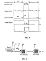
- FIG. 1 depicts NO x adsorption and reduction in an illustrative NSR system.
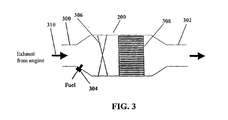
- FIG. 2 illustrates one variation of the system of the present invention wherein a fuel processor is located upstream of a NSR system.
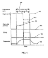
- FIG. 3 illustrates one variation of the fuel processor of the present invention, wherein the fuel processor comprises a single catalyst.
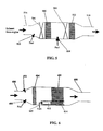
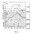
- FIG. 4 provides a time-based graph illustrating one method of operating the fuel processor in accordance with the present invention.
- FIG. 5 illustrates one variation of the present invention wherein the fuel processor comprises two catalysts in series.
- FIG. 6 illustrates one variation of the present invention wherein the fuel processor comprises two catalysts in parallel.
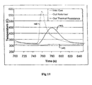
- FIG. 7 provides an illustrative set of thermal response curves for fuel processors having different thermal masses.
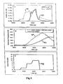
- FIG. 8 provides test results indicating rapid heat up and generation of H 2 using the present invention.
- FIG. 9 provides test results indicating rapid heat up and generation of H 2 using the present invention with an alternative fuel and engine schedule.
- FIG. 10 provides test results using one possible desulfation scheme using the fuel processor of the present invention.
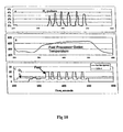
- FIG. 11 provides test results indicating rapid heat up and generation of H 2 and CO using the present invention with a system containing a thermal mass downstream of the fuel processor.
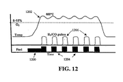
- FIG. 12 illustrates one method of operating the system of the present invention using pulsed fuel flow.
- the present invention provides a system for improving the performance and emission control of IC engines, and in particular, lean-burn engines equipped with a NSR catalyst.
- NSR catalyst When reference is made herein to a "NSR catalyst,” it should be understood that all systems having a NO x adsorbent-catalyst system are embodied thereunder.
- FIG. 1 Making reference now to the drawings, wherein like numerals indicate like elements throughout the views, there is illustrated in FIG. 1 , the operation of a typical NSR catalyst
- the NSR catalyst may be designed so that the adsorption is very efficient, with nearly complete adsorption of NO x from the exhaust stream, as shown by curve 102.
- the NSR catalyst typically comprises a canister situated in the exhaust unit to enable the exhaust gas to flow therethrough.
- Typical catalysts are honeycomb like, monolithic structures having the adsorbent and catalyst components coated onto their surfaces or walls.
- the adsorbent in the NSR catalyst becomes saturated with NO x , the adsorption becomes less complete and the NO x level exiting the NO x trap begins to increase as shown by curve 104.
- the composition of the exhaust stream is changed from an oxidizing to a reducing state, and reduction cycle 106 begins.
- a reducing agent is then introduced and the oxygen level is reduced to zero as shown by curve 108.
- the NO x is desorbed from the adsorbent and is reduced to nitrogen by the catalytic components of the NO x trap.
- This reaction generally occurs with sufficient speed so that reduction cycle 106 is relatively short while at the same time permits sufficient time to elapse so that a significant fraction of the NO x adsorption capacity is regenerated.
- the exhaust composition then reverts back to its normal oxidizing condition, and the entire cycle is repeated.
- adsorption cycle 100 lasts anywhere from 1 to 5 minutes at high load and possibly 20 minutes at low load or idle.
- Regeneration-reduction cycle 106 typically lasts 1 to 10 seconds and possibly longer depending on the time required to regenerate the NSR catalyst.
- the reducing gas composition for regeneration-reduction is obtained by injection of extra fuel into either the engine cylinders late in combustion (i.e., during the end of the power stroke or during the exhaust stroke), or directly into the exhaust pipe upstream of the NSR system.
- the overall NO x conversion or removal performance of this technology is affected by the regeneration-reduction performance of the adsorbent-catalyst system. Thus, if the regeneration cycle is ineffective, the subsequent adsorption cycle is inefficient and the NO x levels exiting the exhaust are typically very high.
- fuel processor 200 may be located at a position along exhaust pipe 202 at a distance between engine 204 and NSR system 206. In this way, the exhaust stream will flow first through fuel processor 200 and then through NSR system 206.
- Fuel processor 200 may be located together with NSR system 206 in a single housing structure, or it may not be. In one variation; as will be described in more detail below, fuel processor 200 is operated intermittently to periodically regenerate the NSR adsorbent of the NSR system 206. When regenerating the NSR adsorbent, fuel 208 may be injected into fuel processor 200, injected at a position upstream of fuel processor 200, or may be injected directly into both fuel processor unit 200 and at a position upstream thereof.
- fuel processor 200 comprises at least one catalyst, as shown in FIG. 3 .
- fuel processor 200 comprises inlet 300, outlet 302, and at least one catalyst 308.
- At least one fuel injection port 304 and an optional mixer 306 are located at a position upstream of the fuel processor.
- fuel processor 200 may further comprise a fuel preheater, fuel vaporizer, a secondary injection port for the introduction of air or additional fuel (not shown), and a control system (not shown).
- fuel processor 200 comprises inlet 300 for receiving exhaust gas mixture 310.
- Fuel injection port 304 is located at a position upstream of fuel processor 200 for receiving fuel therein. After the fuel is injected into port 304, it enters fuel processor 200 and combines with exhaust gas mixture 310.
- the fuel to be injected into port 304 may take the form of a vapor, a liquid, or a combination of the two. If the injected fuel is a liquid, then some or all of it may be vaporized when contacted by the hot exhaust gas mixture. Mixing may further accelerate this vaporization.
- exhaust gas mixture 310 and the injected fuel may pass through an optional mixer 306.
- Mixer 306 may be any suitable mixer that promotes mixing of gases and aids the vaporization of liquid droplets.
- the mixture may be sufficiently uniform so that the resulting equivalence ratio ( ⁇ ) is within any desired limit, where the equivalence ratio is the fuel concentration divided by the theoretical fuel concentration needed to fully react all the oxygen present in the gas mixture to form CO 2 and H 2 O.
- the fuel processor is to be used to reduce the oxygen concentration in the exhaust to zero before it enters the NO x trap, then the level of mixing will determine the required mixture equivalence ratio. If the mixer produces a mixture at the catalyst inlet of +/- 10% uniformity then fuel may be added to give an equivalence ratio of 1.1 so that the lowest equivalence ratio at the catalyst is 1.0.
- the mixture uniformity will likely be determined by the required equivalence ratio and the required temperature to obtain the necessary reforming performance. In general, mixture uniformity from +/- 20% is desirable, while +/- 10% is more desirable, and +/- 6% is most desirable.
- a static (i.e., having no moving parts), in-line mixer that mixes the components into a relatively homogeneous stream is used.
- the mixer acts by changing the flow of the gas stream components, thereby causing mixing of the inlet stream.
- static mixers are commercially available and may be used.
- one type of static mixer has an array of intersecting channels that split the stream into portions, which portions are then rearranged and combined.
- Other types of mixers include swirlers and counter rotating swirlers, which impart a swirl to the gas mixture.
- the swirler may have a portion rotating in one direction and another portion rotating in the opposite direction.
- Pipe sections may also be used as mixers. For example, straight pipe sections with a length/inner diameter ratio (L/D i ) greater than 5 or bent pipe sections may be used.
- the mixer may have moving parts such as fans, turbines, or acoustic energy input devices, which induce turbulence or mixing within the gas streams.
- moving parts such as fans, turbines, or acoustic energy input devices, which induce turbulence or mixing within the gas streams.
- Such mixers may be less desirable, however, since the moving parts may wear and require service and may also require a greater energy input. Evaluation of any improvement in mixing efficiency should be made before determining whether a non-static mixture is sufficiently advantageous to tolerate the additional design complexity and energy consumption.
- varnish or carbonaceous deposits it is possible for varnish or carbonaceous deposits to form on the parts of the mixer in contact with fuel spray, especially if the fuel has a high molecular weight and is prone to pyrolysis.
- Varnish is a hydrocarbon like coating formed by partial pyrolysis of the diesel fuel.
- Parts of the mixer may be coated with a catalyst capable of oxidizing these varnish or carbonaceous deposits. In this way, the catalyst prevents or removes the deposits, much like a continuous-cleaning or self-cleaning oven.
- fuel injection ports may be used as mixers.
- the fuel injection ports are located upstream of the fuel processor in the exhaust pipe and a length of the exhaust pipe is used to mix the gas mixture uniformly. The section of pipe length necessary to perform this function is generally thought to be ten times the pipe diameter length.
- the injection ports may also be located upstream of a bend in the exhaust pipe to further mix the fuel and air. In some instances, it may be desirable to mix the fuel and air quickly or in a short distance prior to their introduction into the catalyst. This is because heavy fuels (e.g., diesel fuels) are prone to pyrolysis or decomposition and produce varnish or other deposits, which may in turn lead to the degradation of the system.
- the fuel injection ports of the engine are used as mixers.
- the fuel and exhaust mixture then flow into catalyst 308 for reaction.
- a portion of the fuel reacts with oxygen, while the remaining fuel reacts with water to form carbon monoxide (CO) and hydrogen (H 2 ) by processes well known in the art.
- the H 2 and CO then flow out of catalyst 308 and out of the fuel processor via outlet 302.
- the H 2 and CO may then flow downstream to NSR system 206, as shown in FIG. 2 . Since the gas mixture comprises a H 2 and CO reducing gas mixture, containing little or no oxygen, the NSR unit will be rapidly and efficiently regenerated. At the completion of this regeneration cycle, the fuel flow to the fuel processor is terminated and the system returns to adsorption mode.
- Catalyst 308 may comprise a single catalyst unit or may comprise several catalysts in series.
- a first catalyst may be designed primarily as a combustion catalyst with a catalyst composition selected to react with some of the fuel and oxygen to form carbon dioxide and water and generate heat. Excess fuel and/or fuel injected between catalyst units could then pass to a second catalyst unit where the excess fuel can react with water and carbon dioxide to form CO and H 2 .
- This second catalyst can be designed primarily as a reforming catalyst for example.
- a single catalyst can be designed having an inlet section for oxidation and an outlet section for reforming. In this way, a single catalyst is provided that effectively functions as two separate catalyst units.
- Catalyst 308 may comprise one or more metals or oxides as the active catalyst combined with a high surface area refractory support, many of which are well known in the art for oxidation of hydrocarbons.
- the catalyst may be applied as a washcoat, a porous coating typically comprising a mixture of a high surface area support and active catalyst elements.
- the coating may comprise a support with a porous structure that has a second oxide portion or a mixture of oxides active for the oxidation of hydrocarbons or carbon.
- the coating may be applied using any number of processes.
- a catalyst composition that may be used with the present invention is described in U.S. Patent No. 5,232,357 by Dalla Betta et. al .
- the fuel used in the fuel processor may be any fuel compatible with the unit.
- it may be the same type of fuel as used in the engine.
- the fuel is a liquid, such as diesel fuel or gasoline
- the exhaust gas mixture may not be hot enough to vaporize the fuel completely.
- the mixture temperature may be increased sufficiently to cause some portion of the fuel to react with the oxygen in the exhaust stream passing through the catalyst, thereby causing the catalyst temperature to increase.
- the remaining liquid fuel may be vaporized within the catalyst.
- the fuel may be preheated so that it is more readily vaporized upon injection.
- An optional fuel heater may be positioned at any convenient location, either within the fuel processor unit itself, or any desirable position upstream thereof
- the fuel may be injected either continuously or intermittently, for the duration of the regeneration cycle. In the case of continuous fuel injection, the rate and duration of the fuel flow controls the fuel quantity. In the case of intermittent fuel injection, the pulse frequency and pulse volume controls the fuel quantity.
- fuel may first be injected 1200 into the fuel processor in order to preheat the fuel processor catalyst to a desirable temperature 1202.
- the fuel processor catalyst may be preheated to a temperature in the range of 500°C ( ⁇ 50°C) to 700°C ( ⁇ 50°C), and most often in the range of 600°C ( ⁇ 50°C).
- Fuel may then be injected in a pulsed manner 1204 so as to generate pulses of H 2 and CO 1206, which are then used to regenerate the NSR unit.
- the pulses may be of any duration, but should be sufficiently short so as to allow the fuel processor catalyst time to cool down in between successive pulses. If the fuel pulses are too long, the catalyst may overheat, since high levels of oxygen, when fully combusted, result in a large heat release.
- any number of pulses may be used, for example, 1 to 20 pulses, and more often, 5-10.
- Figure 12 shows a long pulse of fuel to preheat the catalyst and then 6 large fuel pulses to generate 6 pulses of H 2 /CO 1206 to regenerate the downstream NSR catalyst.
- the length of each pulse may be selected so that the catalyst temperature will remain high during the pulsing series, but will not become high enough so as to cause the catalyst to overheat.
- the pulses could be from 0.1 to about 2 seconds in length.
- the time interval between pulses may be varied depending on the mode of engine operation, and the design of the fuel processing catalyst and the exhaust flow rate being treated.
- the pulses can be farther apart since the lower gas flow rate cools the catalyst more slowly.
- the pulses may be from 0.5 second to 20 seconds apart.
- the pulses may be closer together, from 0.1 to 3 seconds apart. This is often made possible by the use of a pressurized fuel injector, which may be electronically controlled, that enables the fuel injection to be controlled at frequencies of up to 200 Hz.
- this method of pulsed operation allows higher levels of oxygen in an exhaust stream to be used, without overheating the fuel processor catalyst.
- this method of operation may be used with exhaust streams containing 5-20% oxygen, and more often with exhaust streams containing from 8 ( ⁇ 2%) to 15% ( ⁇ 2%) oxygen.
- the catalyst is allowed to cool between the pulses of rich fuel in order to prevent overheating.
- the quantity of fuel injected is typically sufficient to react with all of the excess oxygen present in the exhaust stream and to generate the required amount of reducing gas mixture (CO and H 2 ) at the operating temperature of the NSR system.
- This quantity of fuel corresponds to an equivalence ratio ( ⁇ ) greater than 1.
- Fuel is generally not injected during the NO x adsorption phase, which typically lasts 1 to 5 minutes at high loads and longer at low load or idle. Then fuel is injected again for about 1 to 10 seconds during the NO x regeneration-reduction phase, and the cycle is repeated as long as the engine is operating and is producing NO x .
- the quantity and timing of fuel injection may be optionally controlled by a fuel processor control system, which may be linked to or be part of, the engine management system or engine control unit.
- the H 2 and CO reducing agent can be formed by a variety of reactions.
- a portion of the fuel is combusted to raise the catalyst temperature to approximately 500 to 700°C and the remaining fuel reacts with H 2 O and CO 2 in the exhaust stream or formed by the fuel combustion to produce the desired H 2 and CO.
- the fuel, O 2 , H 2 O, and CO 2 can react simultaneously on the catalyst to yield the desired H 2 and CO.
- the fuel processor can be operated in any of several modes.
- One mode of operation is shown for example, in FIG 4 .
- the regeneration cycle 400 consists of a heat up phase A and a reduction phase B.
- the oxygen concentration 402 from the engine, fuel flow to the fuel processor 404, CO and H 2 produced by the fuel processor 406 and temperature of the fuel processor catalyst 408 are indicated.
- fuel is injected to the fuel processor at a rate indicated by 410. This heats the fuel processor catalyst to the desired temperature as shown in curve 408.
- the fuel flow is increased 412 and the oxygen level 402 is decreased by partially throttling the airflow to the engine.
- the combination of decreasing the oxygen concentration and increasing the fuel concentration causes the overall mixture at the fuel processor catalyst to become rich, that is, having an equivalence ratio of greater than 1, and CO and H 2 is produced as shown in curve 406.
- the NO x trap within the NSR system is fully regenerated, fuel input to the processor is terminated and the engine throttle reopened.
- One advantage of this cycle is that fuel consumption is minimized.
- the engine is throttled only during the period in which CO and H 2 is generated, any negative effects on engine performance and drivability are minimized.
- the fuel flow into the fuel processor can be immediately raised to that level required for reducing agent generation. Then when the fuel processor has achieved an adequate temperature, the engine may be throttled to produce an overall reducing mixture of CO and H 2 . This can facilitate faster fuel heat up of the fuel processor catalyst since the amount of fuel combustion is higher. However, particular care should be taken in order to avoid overheating the catalyst, thereby deactivating it.
- the outlet gas stream from the fuel processor is free of oxygen, including oxygen that might bypass catalyst 308. This is because this oxygen will mix with the reducing gas mixture and react on the NSR catalyst thus reducing the effectiveness of the regeneration process.
- the engine operating procedure can take a number of forms. Rather than throttling the engine to reduce the exhaust oxygen concentration, the exhaust gas recirculation system ("EGR") flow can be increased, thus causing the exhaust oxygen level to decrease. Alternatively, the amount of fuel injected into the engine by the engine fuel injectors can be increased. In addition, a combination of these methods or other methods can be used to decrease the exhaust oxygen level.
- the fuel processor comprises catalysts in series.
- an oxidation catalyst is positioned upstream of a reforming catalyst as shown in FIG 5 .
- fuel processor unit 200 comprises oxidation catalyst 500 upstream of reforming catalyst 502.
- the exhaust gas flow enters the fuel reformer through inlet 504 and passes through mixer 506, oxidation catalyst 500, second mixer 508, reforming catalyst 502 and then through outlet 510.
- fuel may be injected via fuel injector 512 and be reacted on oxidation catalyst 500 to heat up the reforming catalyst 502.
- fuel may also be injected via fuel injector 514 to further increase the fuel/air ratio to reforming catalyst 502 so that reforming can occur to produce CO and H 2 .
- One advantage of this variation is that the functions of the oxidation and reforming catalysts are separated. In this way each catalyst may perform their function very efficiently.
- oxidation catalyst could be configured to operate under constant conditions of excess oxygen (equivalence ratio less then 1.0), thereby facilitating high activity and low deposition of carbon or hydrocarbons.
- reforming catalyst 502 may be separately fueled via one or more injectors at a position near fuel injector 514, the fuel can be added once the temperature of the reforming catalyst has reached its optimal level.
- having a separate oxidation catalyst enables its placement close to the engine, thereby facilitating its operation at higher exhaust gas temperatures. This in turn helps provide better operation at idle and at low ambient conditions.
- the two catalysts in series in this variation may have any number of configurations.
- the catalysts may be located at a distance separate from one another and have separate upstream injectors and mixers.
- the two catalysts may be located within a single unit. Having the catalysts located within a single unit has the advantage of making each system easily replicable, thus providing a manufacturing advantage.
- the catalysts are in parallel, as shown by FIG. 6 .
- the exhaust gas enters through port 600.
- Fuel may be injected via fuel injectors 602 where it is then mixed with the exhaust gas by mixer 604.
- the fuel and exhaust mixture then passes through catalyst 606 and outlet 608.
- a portion of the exhaust mixture passes through passage 612 and then through catalyst 614 and on to common outlet 608.
- Catalyst 606 is an oxidation catalyst and catalyst 614 is a reforming catalyst or combination combustion and reforming catalyst that has separate fuel injector 610.
- fuel is first added to fuel injector 610, which heats up reforming catalyst 614 to the desired temperature.
- fuel is injected via injectors 602 at an equivalence ratio close to 1.0. This consumes the oxygen in the main exhaust flow.
- additional fuel may be added via injector 610 to make the equivalence ratio of the mixture at catalyst 614 above 1.0 and to produce CO and H 2 .
- the equivalence ratio of the mixture at catalyst 614 will increase when fuel is injected through injectors 602. This is because the fuel is mixed with the portion of the exhaust flow that is flowing to catalyst 614, making the fuel composition at catalyst 614 the sum of the equivalence ratio from injectors 602 and 610.
- the overall system design may be modified in any number of ways.
- the system may be modified so that fuel from injectors 602 is not mixed with the exhaust flow that goes to catalyst 614.
- the catalysts may be located at positions separate from one another. For example, they may be located in separate units and have separate fuel injectors and mixers.
- One advantage of the parallel configuration illustrated by FIG. 6 is that the reforming catalyst can be preheated to a high temperature by applying fuel only to the section nearby. If the size of catalyst 614 is small relative to catalyst 606 and the fraction of exhaust flow through 614 is small compared to 606, then the amount of fuel used to heat reforming catalyst 614 to the desired reforming temperature would be minimized. Also, catalyst 614 can be designed with a very small thermal mass so that heat up occurs quickly, further minimizing fuel expenditure.
- the downstream NSR system catalyst may not be heated too high in temperature since this may damage it or drive it out of its desired operating range for adsorption. This may be accomplished by increasing the thermal mass of catalyst 606 so that when fuel is added to injectors 602 to remove the oxygen from the main exhaust flow, the catalyst and the exit gas flow from 606 rises slowly.
- a thermal mass may be placed downstream of the fuel processor unit to absorb the heat from the fuel processor outlet stream and reduce the gas stream temperature prior to entering the NSR system.
- the bypass may comprise a pipe or duct allowing the exhaust to flow around the fuel processor system, and a valve, for damper to direct the exhaust flow either through the fuel processor catalyst or around the fuel processor catalyst.
- the catalysts of the present invention may be composed of any suitable material.
- they may be composed of pellets or beads in a container, or may be monolithic honeycomb type units.
- a monolithic honeycomb unit may be desirable because vehicle vibration may cause abrasion and loss of pellet or bead material. Additionally, the monolithic units typically have a lower pressure drop for the flowing exhaust stream.
- Any monolith may be used.
- the monolith may be ceramic or may be metal and may have a variety of cell sizes and shapes. Determination of the cell size and shape is dependent on the desired surface area and pressure drop, as well as the relevant heat and mass transfer coefficients: For example, it may be desirable that the fuel processor catalyst have a low heat.capacity so it can heat up quickly. Similarly, it may be desirable that the fuel processor catalyst have a low pressure drop so that the overall pressure drop of the entire system does not present a hindrance to operation or reduce the efficiency of the engine.
- a monolithic structure When a monolithic structure is used for the catalyst substrate, its external or wall surfaces may be coated with a layer of catalyst.
- This washcoat may comprise a porous inert oxide such as alumina or zirconia and have a highly exposed surface area.
- This oxide support may contain additional components active for oxidation or reforming depending on the desired function.
- Preparation and composition of various monolithic catalysts for use with the present invention are described in U.S. Patent Nos. 5,183,401 , 5,259,754, and 5,512,250 to Dalla Betta et. al.
- the oxidation catalyst may comprise any catalyst capable of oxidizing hydrocarbons.
- the oxidation catalyst may comprise elements selected from any of Groups VI, VII, VIII and IB of the periodic table of the elements.
- the more active catalytic elements may be selected from the group Pd, Pt, Ir, Rh, Cu, Co, Fe, Ni, Ir, Cr, and Mo. In some instances, it may be more desirable to use Pd, Pt, Rh, Co, Fe, or Ni, which may be used separately or in combination and may further exist as the element or the oxide in actual use.
- oxidation catalyst One property of the oxidation catalyst that may be desirable is that it has good catalytic activity at very low temperatures. In this way, oxidation can be initiated at low exhaust temperatures without modification of the system design. This property is often referred to as light off temperature, or the temperature at which the fuel and oxygen in the exhaust begins to react. This typically requires that the temperature be below 250°C and more typically below 150°C.
- the oxidation catalyst may be deposited on supports comprising aluminum oxide, silicon oxide, zirconium oxide, or mixtures and combinations thereof, or mixtures or combinations thereof with additional components or elements.
- supports comprising aluminum oxide, silicon oxide, zirconium oxide, or mixtures and combinations thereof, or mixtures or combinations thereof with additional components or elements.
- cerium zirconium oxide mixtures or solid solutions silica alumina, Ca, Ba, Si, or La stabilized alumina, as well as other supports well known in the art.
- the catalyst may also contain catalytic components active for steam cracking of the hydrocarbon fuel.
- Possible additives may include basic oxides such as calcium oxide, barium oxide, other alkali or alkaline earth oxides and rare earth oxides.
- the catalyst can be made by impregnating Pd, Pt or any other active catalyst within a porous support such as alumina or zirconia.
- the metal loading could be in the range of 0.1 to 20% by weight, and more desirably, in the range of 1 to 10% by weight.
- Several illustrative catalysts that may be used with the present invention include those described in U.S. Patent No. 5,232,357 to Betta et. al. , which is hereby incorporated by reference in its entirety.
- the reforming catalyst may similarly use a high surface area support with added active components.
- the reforming catalyst may comprise components Ni, Rh, Pd, Pt.
- the catalyst may be selected so that it is capable of remaining stable under normal lean oxidizing conditions and then responding very quickly to the addition of fuel so that H 2 and CO are thereby reformed. In this respect, it may be desirable to use Pt, Pd and Rh supported on a porous oxide support.
- a typical reforming catalyst may comprise 1% Rh by weight supported on a porous zirconium oxide substrate. This may be accomplished by dissolving rhodium trichloride in water and then impregnating the solution onto a solid zirconium oxide substrate having a high surface area (e.g., ranging from 15 to 150 m 2 /g).
- the rhodium concentration may typically be in the range of 0.1 to 20% by weight of the total washcoat catalyst solid. More typically, the rhodium concentration may be in the range of 1 to 10% of the total washcoat loading.
- the washcoat may be coated onto the interior channels of a monolithic honeycomb structure at a loading thickness of 1 to 50 mg/cm 2 or more typically, in the range of 5 to 15 mg/cm 2 .
- Pd or Pt catalysts may be prepared in a similar manner.
- the oxidation and reforming catalysts may be combined in the same monolithic unit by combining in the washcoat both the oxidation and reforming components.
- the active oxidation catalyst Pd and the active reforming catalyst Rh may be combined on a zirconia support to form a catalyst having the oxidizing activity to react the fuel with the oxygen and the reforming activity necessary to reform the remaining fuel to CO and H 2 .
- the Rh component may be coated onto the monolithic substrate and calcined or fixed.
- the Pd may be coated onto a high surface area support and calcined or fixed.
- These catalysts may also be mixed together to form a Pd/Rh catalyst and this mixed catalyst then coated onto the monolithic substrate.
- a thermal mass is used to help control the system operation, and in particular, to help moderate the temperature between the fuel processor and the NO x trap catalyst. This may be important because while the optimal operating temperature range for the fuel processor may be quite high, the optimal operating temperature range for the NSR system might not be. This may be because the NO x trap catalyst may be deactivated at high temperatures. Any number of thermal mass configurations are possible for use with the present invention and any number of thermal masses may be employed.
- the thermal mass of the fuel processor catalyst itself is selectively controlled. For example, it may be desirable that the catalyst heats up as rapidly as possible to consume as little fuel as possible. This typically involves controlling the thermal mass of the fuel processor catalyst, so that it is as relatively small.
- a thermal mass may be placed downstream of the fuel processor to absorb the heat it releases in order to help prevent the overheating of the NSR system. This thermal mass may be a PM filter or soot trap placed between the fuel processor and NSR system or may be a separate thermal mass component. When a soot or PM filter is placed between the fuel processor and the NSR system as the thermal mass, the NSR system may be maintained at a constant temperature.
- the heat generated by the fuel processor may be used to heat up and regenerate the particulate trap by helping to burn off the carbonaceous soot.
- the thermal mass may be made of any suitable material.
- it may be ceramic or may be metal. It can have a high heat capacity and a low pressure drop to ensure that the pressure drop across the entire system does not hinder system operation.
- the optimal range of thermal mass is a function of at least the gas flow rate and the desired temperature rise, and thus may be selectively controlled.
- the NSR system itself may be designed with a high thermal mass.
- FIG. 7 provides results of a computer simulation of catalyst heat up during the combustion of a fuel and air mixture. The following assumptions were made: the energy release required was for complete combustion of diesel fuel; the energy of the combustion was used to heat the gas mixture flowing through the catalyst and to heat the catalyst itself; there was good heat transfer between the gas and the catalyst; and the gas flow rate was typical of a catalyst unit sized for a vehicle.
- the catalyst unit heats up rapidly once the fuel is turned on.
- the catalyst unit reaches 450°C in about 12 seconds.
- a wall thickness of 50 microns it reaches 450°C in about 6 seconds and at a wall thickness of 25 microns, it reaches 450°C in about 3 seconds.
- a low wall thickness with a resulting low thermal mass is desirable.
- design considerations that may influence the selection of the wall thickness or thermal mass. These include the mechanical durability of the catalyst and the resistance to oxidation of the metal.
- Typical wall thickness for a metal monolithic reforming catalyst unit would be in the range of 10 to 200 microns, and more typically 25 to 50 microns.
- the oxidation catalyst unit in the parallel configuration of FIG. 6 or a thermal mass in a series configuration, could be substantially thicker, typically 50 to 500 microns and more typically 100 to 200 microns.
- it may be desirable to have the reforming catalyst heat up rapidly to generate hydrogen quickly it is often not desirable to have the oxidation catalyst heat up too rapidly since this may overheat the downstream NSR catalyst.
- the present invention facilitates desulfation of a NO x trap.
- Sulfur in engine fuel produces sulfur oxides, SO 2 or SO 3 , in the exhaust system. These sulfur oxides (“SO x ”) can react with the components of the trap to form sulfates, which in turn can deactivate the NSR system. While typical levels of sulfur in fuel are relatively low, making the deactivation of the trap take anywhere from days to weeks (corresponding to 100's to 1000's of miles of engine usage), the trap must be able to work far longer than this. The system and methods of the present invention can thus be used to desulfate the trap.
- this is accomplished by the incorporation of a sulfur trapping material in at least a portion of the fuel processor.
- the sulfur trapping material may be included as a composition of the fuel processor catalyst. This sulfur trapping material traps the SO 2 or SO 3 in the engine exhaust before it can reach the downstream NSR catalyst and; therefore, prevents deactivation of the NSR catalyst.
- the fuel processor will likely become saturated. If this occurs, the fuel processor should be regenerated to ensure continued useful operation. This regeneration may, for example, be done during the rich cycle when fuel is injected into the fuel processor.
- This regeneration may, for example, be done during the rich cycle when fuel is injected into the fuel processor.
- the sulfur trapping material can be incorporated into the fuel processor catalyst in any number of ways. For example, it can be uniformly distributed within the catalyst layer, or it can be included as a separate layer, either at the side closest to the flowing gas stream or at the side closed to the catalyst support wall.
- the sulfur trapping material may also be a band located at the outlet end of the fuel processor catalyst where it would be exposed to the H 2 and CO generated by the fuel processor.
- the sulfur trapping material may also be a separate catalyst unit positioned downstream of the fuel processor catalyst. It is often most desirable that the sulfur trapping material is a catalyst band located at the outlet of the fuel processor catalyst, or that the sulfur trapping material is a separate catalyst downstream of the fuel processor catalyst.
- desulfation of the system is accomplished by operating the oxidation portion of the fuel processor to produce an outlet gas stream having a temperature in the range of 500 to 800°C. This in turn heats the downstream NSR system to a temperature in the range of 500 to 700°C.
- the fuel flow to the fuel processor and the engine throttle may be adjusted to produce H 2 and CO and reduce the oxygen concentration exiting the fuel processor to zero.
- This reducing gas mixture will then regenerate the NO x trap by decomposing the sulfates and other species that have caused its deactivation.
- This hot reducing gas mixture can be maintained until the regeneration is complete.
- the regeneration temperature range for the NSR system is typically from about 100 to 800°C and more typically, from about 500 to 700°C.
- the H 2 and CO reducing agent can be fed to the NSR catalyst for regeneration as a continuous long reducing pulse or as many short pulses.
- a control processor or control system may be used to control various aspects of the present invention. Any number of control strategies may be employed. For example, a control system may be used to map NO x output versus a given engine operating condition, such as load or speed. In this way, the NO x collected by the NSR trap may be estimated and as the trap reaches capacity, the NO x regeneration cycle may be initiated. Alternatively, a NO x sensor may be placed downstream of the NSR trap. In this way, once the sensor perceives that the NO x trap has reached capacity (e.g., by measuring breakthrough NO x levels), the regeneration cycle may be initiated.
- a control system may be used to monitor and control any or all system temperatures.
- Illustrative temperatures that may be controlled include inlet and outlet gas mixture temperatures, fuel input temperature, and catalyst temperature.
- the reformer catalyst temperature may be monitored and controlled via a thermocouple or other temperature-sensing device placed near the outlet of the catalyst.
- the temperature at the outlet of the fuel processor can be measured and monitored using a thermocouple.
- the temperature may be controlled by adjusting the fuel flow to the fuel processor while leaving the oxygen level in the exhaust constant.
- the temperature may be controlled by keeping the fuel flow to the fuel processor constant while adjusting the oxygen level, for example, by throttling the engine.
- Yet another alternative is to adjust both the fuel flow to the fuel processor and the O 2 level. This would allow the system to control both the fuel processor outlet temperature, and the equivalence ratio. In this way, the level of H 2 and CO may be effectively controlled.
- the fuel processor temperature may be monitored by measuring the gas temperature at the outlet or by measuring the actual temperature of the catalyst itself.
- a combustibles sensor, or H 2 or CO sensor may be placed downstream of the NSR trap unit to sensor the breakthrough of H 2 and CO reducing agent. This in turn signals the control system to stop the regeneration cycle.
- the fuel processor unit is used to desulfate the NSR trap unit, then it may be desirable to measure the temperature at the outlet of the fuel processor unit to limit the operating temperature to insure durability. In addition, the temperature at the outlet of the NSR trap unit may be measured to ensure that the NSR unit is at the desired temperature for regeneration. In addition, the temperature of the fuel processor unit may be modulated to obtain the desired temperature of the NSR unit for proper desulfation.
- a control system may also be used to control the equivalence ratio.
- the equivalence ratio at the inlet to the reformer catalyst can be controlled by changing the fuel flow or by throttling the airflow to the engine. More specifically, at normal operating engine airflow, fuel may be added to the reformer catalyst until the temperature is within the range required for reforming the fuel to H 2 and CO. At this point, the engine airflow can be throttled to reduce the airflow and O 2 concentration in the exhaust. This in turn will increase the equivalence ratio at the catalyst and drive it into the rich region to generate H 2 and CO. It is also possible to adjust the fuel flow to the reformer to adjust the equivalence ratio or to adjust both the engine throttle and the fuel flow to obtain the desired reformer equivalence ratio.
- the equivalence ratio at the reformer and at the oxidation catalyst can be calculated from a number of engine parameters, including engine RPM and throttle setting (which in turn provides engine air flow), engine fuel flow, and fuel processor fuel flow(s).
- the exhaust O 2 level can be measured using an O 2 sensor in the exhaust upstream of the fuel processor and combined with the fuel processor fuel flow to calculate equivalence ratios.
- One illustrative control strategy that may be specifically employed comprises the following steps: (1) adding fuel under normal operating conditions (for example, approximately 8-15% O 2 ) to heat the fuel processor catalyst to operating temperature; (2) adjusting the engine such that the oxygen concentration in the exhaust is between 4-6%; (3) adjusting the fuel to achieve the desired equivalence ratio (for example by exhaust gas recirculation or by throttling the intake air to the engine); (4) increasing the fuel flow rate so that an equivalence ratio > 1 is obtained (for example, in the range of 2-5) or if the fuel flow rate is already sufficiently high, lowering the exhaust O 2 ; (5) maintaining conditions until the NO x trap is regenerated; (6) turning the fuel off and resuming normal engine operation.
- normal operating conditions for example, approximately 8-15% O 2
- Another illustrative control strategy that may be specifically employed comprises the following steps: (1) starting the fuel flow into the fuel processor and at the same time lowering the engine exhaust O 2 ; (2) adjusting the fuel flow rate after the fuel processor has reached a desired temperature so that a desired equivalence ratio is obtained; (3) maintaining the fuel flow until the NO x trap is regenerated; (4) turning the fuel off and resuming normal engine operation.
- the exhaust temperature into the fuel processor could be adjusted by changing the engine operating conditions. For example, if the exhaust temperature at the inlet of the fuel processor is too low to obtain reaction between the fuel and the exhaust O 2 , then the engine operation can be changed to increase the exhaust temperature. Possible engine changes include decreasing the engine intake air, increasing the amount of EGR, or bypassing a turbocharger. Similarly, a temperature measurement may be used to control the exhaust gas temperature. For example, the temperature at the inlet or outlet of the fuel processor may be measured and used as an indicator of the exhaust gas temperature. In this way, the exhaust temperature can be controlled.
- a model based control strategy for use with the present invention may also be used as follows.
- the regeneration cycle can be performed only when the NSR NO x adsorbent has reached a high level of saturation. This would help minimize the frequency of regeneration and the fuel cost associated with the regeneration.
- maximum loading of the NSR NO x adsorbent for example in moles of NOx (ML, NOx ) may be determined.
- the total flux of NO x into the NSR catalyst may be estimated from a measurement of the NO x concentration at the catalyst inlet using a NO x sensor positioned in the exhaust stream.
- This exhaust NO x concentration (C NOx ) can be combined with the exhaust flow rate (F exh ) in a mathematical function to calculate the total amount of NO x flowing through the NSR catalyst (L NOx ) by integrating over time (t) Eqn. 1.
- the regeneration cycle can be initiated. For example, prior testing may be used to establish that desirable NO x control may be attained by the NSR catalyst if the level of NO x saturation is below 80%. In this case, when L NOx is 80% of ML NOx , the regeneration cycle is started. It should be noted that the ratio of L NOx to ML NOx when regeneration is initiated could be a function of average exhaust temperature during the NO x adsorption period, rate of NO x generation, average engine load, or other parameters that may affect the capacity of the NSR catalyst NO x adsorbent.
- ML NOx may be a function of total catalyst operation time such as engine hours, vehicle miles or even integrated total NO x produced by the engine. Also, as described below, the exhaust NO x concentration and the exhaust flow rate and other parameters could be estimated from engine operating parameters.
- the fuel flow to the fuel processor may be controlled to give either a desired heat release rate or a desired equivalence ratio.
- the fuel flow rate (F fuel ) may be a function of the exhaust temperature at the fuel processor inlet (T FP,in ) the total exhaust flow rate (F exh ) and several fixed parameters such as the fuel processor catalyst mass, desired rate of heating and heat of combustion of the fuel and other system constants (SC) that can vary by engine type, catalyst size, etc. This functional relationship is shown in Eqn. 2.
- the fuel flow to the fuel processor is controlled to a desired equivalence ratio, then the fuel flow will also be a function of the O 2 concentration in the exhaust stream (E O2 ) and the desired equivalence ratio for operation of the fur processor (R eq ) as shown in Eqn. 3.
- the O 2 concentration in the exhaust stream can be measured using a sensor positioned in the exhaust stream.
- the parameters in Eqn. 1 through 3 can be calculated or estimated from operating parameters of the engine.
- the exhaust flow rate may be a function of the engine inlet air flow rate, which may be measured as part of the engine control system.
- the exhaust flow rate could be calculated from certain engine parameters such as engine rpm and turbocharger boost pressure.
- exhaust flow can be expressed as a function of engine rpm (E rpm ) and engine turbocharger boost pressure (E boost ) as shown in Eqn. 4.
- Other engine parameters may also be included if needed to obtain a more accurate estimation of exhaust flow rate.
- the concentration of O 2 or NO x in the exhaust can be estimated from one or more engine operating parameters such as engine fuel flow rate (E fuel ), engine rpm (E rpm ), engine output torque (E torque ), turbocharger boost pressure (E boost ), engine EGR flow (E EGR ), as well as other possible engine parameters.
- This exhaust O 2 concentration may be determined as shown in Eqn. 5 and similarly determined for exhaust NO x concentration as shown in Eqn. 6.
- E O ⁇ 2 f E fuel , E rpm , E torque , E boost , E EGR , etc .
- E NOx f E fuel , E rpm , E torque , E boost , E EGR , etc .
- the fuel processor fuel rate may be calculated or estimated from engine parameters.
- control strategies described above can be in the form of mathematical expressions in the engine or emissions system control unit or these expressions can be reduced to one or more multidimensional tables, so called look-up tables, stored in the engine control unit.
- Other system variables such as fuel processor equivalence ratio, length of time the fuel processor is operated in the rich mode, operating temperature of the fuel processor, and other aspects of the fuel processor, can be determined in a similar manner.
- any number of sensors, microprocessors, fuel flow rate regulators, and throttle regulators may be used, all of which are well-known in the art.
- the present invention may be further understood with reference to the following non-limiting examples.
- Example 1 A monolithic catalyst was prepared as described in U.S. Patent No. 5,259,754 to Dalla Betta et. al. Rhodium trichloride was dissolved in deionized water at a concentration of about 0.18 g Rh/cc and then zirconium oxide powder with a surface area of about 75 m 2 /g was added with stirring. While stirring the mixture, a solution of 20% ammonium hydroxide in water was then added to a pH of 8. The mixture was then evaporated to dryness and the resulting powder calcined in air at 700°C for 10 hours. The final rhodium concentration was 5.5% Rh by weight on the final catalyst. The Rh/ZrO 2 catalyst was slurried with water and a 10% by weight of a 20% zirconium acetated solution to form a slurry of about 30% solids.
- a strip of River Lite 20-5 Sr from Kawasaki Steel Company with a thickness of 0.050 by 75mm wide and 3 m length was corrugated to form V-shaped channels across the 75mm width with the V-channels in a herringbone pattern.
- the channels were approximately 0.8 mm in height.
- This foil was treated in air at 900°C for 10 hours to form a layer of aluminum oxide on the surface.
- the Rh/ZrO 2 slurry was then sprayed onto both sides of the foil to a loading of approximately 6 mg/cm 2 .
- the coated catalyst was then calcined in air at 700°C for an additional 10 hours.
- the foil section was then folded into two and rolled to form a non-nesting spiral roll with open longitudinal channels.
- the final catalyst had a diameter of 50 mm and contained about 17g of catalyst washcoat.
- Example 2 The catalyst from Example 1 was placed in a flow reactor comprising a gas supply and mass flowmeters for air, nitrogen and helium as a mass spectrometer quantitative tracer, an electric heater, an air assist sprayer for water, a second air assist sprayer for diesel fuel and a static mixer upstream of the catalyst.
- the catalyst was contained in a 50 mm diameter insulated section with thermocouple temperature sensors upstream and downstream of the catalyst.
- a sampling probe for a mass spectrometer was located about 50 cm downstream of the catalyst outlet. Air, nitrogen and water flow was adjusted to form a mixer flowing at 800 SLPM (standard liters per minute) with a composition of 5% H 2 O 8% O 2 , 0.3% He and the balance N 2 . This mixture was then heated to 370°C using the electric heater. Results of the tests conducted are provided in FIG. 8 .
- FIG. 8A shows the mass spectrometer signal for H 2 and CO 2 converted to concentration units of percent by volume.
- FIG. 8B shows the temperature of the gas at the outlet of the catalyst as measured by three thermocouples placed just downstream of the catalyst at different locations across the outlet face.
- FIG. 8C shows the concentration of O 2 in percent and the fuel flow in g/min as set by the control system. At time equal to 298 seconds, fuel was turned on at 10 gm/minute flow rate. This fuel was combusted on the catalyst and the catalyst temperature rose rapidly as shown by the temperature of the three thermocouples in FIG. 8B . That combustion is occurring was confirmed by the immediate appearance of CO 2 as measured by the mass spectrometer as shown in FIG. 8B .
- FIG. 9 shows another example of hydrogen pulse generation.
- the catalyst used in this example was prepared in a manner similar to that of Example 1 with the exception that the metal foil was corrugated to have a channel height of 1.2mm. Air, nitrogen and water flow was adjusted to form a mixture flowing at 200 SLPM (standard liters per minute) with a composition of 8% H 2 O, 5% O 2 , 0.3% He and the balance N 2 . This mixture was then heated to 300°C using the electric heater.
- Graph A shows the mass spectrometer signal for H 2 and CO 2 converted to concentration units of percent by volume.
- Graph B shows the temperature of the gas at the outlet of the catalyst 906 and inside the catalyst at one inch from the outlet 904 as measured by two thermocouples.
- Graph C shows the fuel flow in g/min as set by the control system.
- fuel was turned on at 1.8 gm/minute flow rate. This fuel was combusted on the catalyst and the thermocouple near the catalyst inlet rose rapidly.
- the fuel flow is increased to 6.5g/min to provide a faster rate of temperature rise as shown by the temperature of the thermocouples in graph B. That combustion is occurring was confirmed by the immediate appearance of CO 2 as measured by the mass spectrometer as shown by 900 in graph A.
- the fuel flow is increased further to 10 g/min generate, a fuel rich exhaust as shown by 908 in graph C.
- H 2 appears as measured by the mass spectrometer and indicated by 902 in graph A.
- the fuel flow was terminated. The CO 2 and H 2 level rapidly decreased.
- Example 4 The catalyst of Example 1 was used to demonstrate a possible desufation cycle. Air, nitrogen and water flow was adjusted to form a mixer flowing at 500 SLPM (standard liters per minute) with a composition of 8% H 2 O 8% CO 2 ; 7% O 2 , 0.3% He and the balance N 2 . This mixture was then heated to 250°C using the electric heater. As shown in Figure 10 , at approximately 325 seconds fuel was turned on to raise the fuel processor temperature and produce an outlet gas temperature of 500 to 600°C. This high gas temperature will heat the downstream NSR trap catalyst to 500 or 600°C after a short time period.
- SLPM standard liters per minute
- the exhaust O 2 level is decreased and the fuel flow to the fuel processor is increased, 375 seconds in FIG. 10 , to obtain an equivalence ratio greater then 1 and to produce H 2 and CO to desulfate the NSR catalyst.
- This reducing condition can be maintained for a long period or the reducing pulses containing H 2 and CO can be pulsed as shown in this example. Between pulses, a lower level of fuel is fed to the fuel processor to maintain the fuel processor temperature and the NSR catalyst temperature.
- the fuel to the fuel processing catalyst is turned off and the outlet gas temperature from the fuel processor drops rapidly.
- Example 5 This example demonstrates the effect of a thermal mass in series downstream of the fuel processor.
- the same catalyst as in Example 3 was used.
- the monolithic thermal resistance was assembled from 0.100 inch thick metal foil 100mm wide and corrugated to form a monolithic structure with a channel height of about 1.5 mm and weighing abut 550g.
- This thermal resistance was placed just downstream of the fuel processor catalyst of Example 3 and a thermocouple monitored gas temperatures upstream of the fuel processor catalyst, between the fuel processor catalyst and the thermal mass and downstream of the thermal mass. Air, nitrogen and water flow were adjusted to form a mixture flowing at 600 SLPM (standard liters per minute) with a composition of 8% H 2 O, 8% CO 2 ; 7% O 2 , 0.3% He and the balance N2.
- 600 SLPM standard liters per minute
Landscapes
- Engineering & Computer Science (AREA)
- Chemical & Material Sciences (AREA)
- Chemical Kinetics & Catalysis (AREA)
- Combustion & Propulsion (AREA)
- Mechanical Engineering (AREA)
- General Engineering & Computer Science (AREA)
- Health & Medical Sciences (AREA)
- Toxicology (AREA)
- Analytical Chemistry (AREA)
- General Chemical & Material Sciences (AREA)
- Oil, Petroleum & Natural Gas (AREA)
- Environmental & Geological Engineering (AREA)
- Organic Chemistry (AREA)
- Biomedical Technology (AREA)
- General Health & Medical Sciences (AREA)
- Inorganic Chemistry (AREA)
- Exhaust Gas After Treatment (AREA)
- Electrical Control Of Air Or Fuel Supplied To Internal-Combustion Engine (AREA)
Claims (38)
- Procédé de régénération d'un adsorbant de catalyseur NSR comprenant les étapes consistant à :prendre un courant d'échappement de moteur (310) comprenant de l'oxygène ;préchauffer un catalyseur de dispositif de transformation de combustible (308) à une température d'au moins 500 °C en injectant du combustible dans ledit courant d'échappement (310) en une position située en amont d'un dispositif de transformation de combustible (200), le dispositif de transformation de combustible (200) comprenant une entrée (300), une sortie (302) et ledit au moins un catalyseur de dispositif de transformation de combustible (308) ;injecter ensuite de façon pulsée un combustible à base d'hydrocarbure (208) dans ledit courant d'échappement (310) en une position située en amont dudit dispositif de transformation de combustible (200) ;faire réagir le combustible injecté (208) au sein dudit au moins un catalyseur de dispositif de transformation de combustible (308) pour produire un mélange gazeux réducteur comprenant du monoxyde de carbone (CO) et de l'hydrogène (H2), tout en laissant refroidir ledit catalyseur de dispositif de transformation de combustible (308) entre les impulsions successives, mais en maintenant le catalyseur de dispositif de transformation de combustible (308) à une température d'au moins 500 °C ;introduire le mélange gazeux réducteur dans un catalyseur NSR (206) comportant un adsorbant, moyennant quoi l'adsorbant est régénéré par l'introduction du mélange gazeux réducteur.
- Procédé selon la revendication 1, dans lequel l'étape d'injection pulsée du combustible à base d'hydrocarbure (208) comprend de deux à dix impulsions environ.
- Procédé selon la revendication 2, dans lequel chaque impulsion dure d'environ 0,1 à environ 2,0 secondes.
- Procédé selon la revendication 3, dans lequel la longueur de chaque impulsion et l'intervalle de temps entre chaque impulsion sont choisis de telle manière que le catalyseur de dispositif de transformation de combustible (308) reste à une température d'environ 500 °C à environ 700 °C.
- Procédé selon la revendication 1, dans lequel le courant d'échappement (310) est un échappement de moteur à allumage par compression.
- Procédé selon la revendication 1, dans lequel le combustible (208) est du gazole.
- Procédé selon la revendication 1, dans lequel le combustible (208) est vaporisé avant d'être injecté.
- Procédé selon la revendication 1, dans lequel la concentration en oxygène dans le courant d'échappement (310) est inférieure à 20 %.
- Procédé selon la revendication 8, dans lequel la concentration en oxygène est comprise dans l'intervalle de 8 à 15 %.
- Procédé selon la revendication 1, dans lequel le dispositif de transformation de combustible (200) comprend au moins deux catalyseurs distincts, au moins un catalyseur étant un catalyseur de reformage (502) et au moins un catalyseur étant un catalyseur d'oxydation (500).
- Système permettant de réduire les oxydes d'azote (NOx) dans un courant d'échappement (310) contenant un excès d'oxygène (O2), ledit système comprenant :un catalyseur NSR (206) comportant un adsorbant nécessitant une régénération périodique par l'introduction de monoxyde de carbone (CO) et d'hydrogène (H2) ;un dispositif de transformation de combustible (200) situé en amont du catalyseur NSR (206), comprenant une entrée (300), une sortie (302) et au moins un catalyseur de dispositif de transformation de combustible (308) ; etau moins un orifice d'injection de combustible (304) situé en amont du catalyseur de dispositif de transformation de combustible (308), le système étant adapté pour injecter du combustible dans l'orifice d'injection de combustible (304) et réagir sur le catalyseur de dispositif de transformation de combustible (308) pour faire augmenter rapidement la température dudit catalyseur de dispositif de transformation de combustible (308) à au moins 500 °C afin de préchauffer le catalyseur de dispositif de transformation de combustible (308), puis effectuer l'injection de combustible de manière pulsée de telle façon que le catalyseur de dispositif de transformation de combustible (308) reste à une température d'au moins 500 °C tout en laissant refroidir ledit catalyseur de dispositif de transformation de combustible (308) entre les impulsions successives, moyennant quoi au moins une partie du combustible est convertie en H2 et en CO.
- Système selon la revendication 11, dans lequel ledit dispositif de transformation de combustible comprend un matériau de piégeage de soufre.
- Système selon la revendication 12, dans lequel le matériau de piégeage de soufre est une bande catalytique située à la sortie (302) du dispositif de transformation de combustible (200).
- Système selon la revendication 12, dans lequel le matériau de piégeage de soufre est un catalyseur, différent dudit au moins un catalyseur de dispositif de transformation de combustible (308), et qui est situé en aval dudit au moins un catalyseur de dispositif de transformation de combustible (308).
- Système selon la revendication 11, comprenant en outre une masse thermique ayant une capacité thermique supérieure à celle du dispositif de transformation de combustible (200).
- Système selon la revendication 15, dans lequel au moins une partie de la masse thermique est choisie dans l'ensemble constitué par un filtre à particules, le dispositif de transformation de combustible (200), le catalyseur NSR, une structure monolithique ayant une capacité thermique supérieure à celle du dispositif de transformation de combustible, et leurs combinaisons.
- Système selon la revendication 16, dans lequel au moins une partie de la masse thermique est un filtre à particules et au moins une partie de la masse thermique est une structure monolithique ayant une capacité thermique supérieure à celle du dispositif de transformation de combustible (200).
- Système selon la revendication 11, comprenant en outre un dispositif de préchauffage de combustible, le dispositif de préchauffage de combustible étant situé en amont du dispositif de transformation de combustible et en aval de l'orifice d'injection de combustible (304).
- Système selon la revendication 11, comprenant en outre un dispositif de vaporisation de combustible, le dispositif de vaporisation de combustible étant situé en amont du dispositif de transformation de combustible et en aval de l'orifice d'injection de combustible (304).
- Système selon la revendication 11, comprenant en outre un mélangeur (506), le mélangeur étant situé en amont du dispositif de transformation de combustible (200) et en aval de l'orifice d'injection de combustible (304).
- Système selon la revendication 20, dans lequel le mélangeur est un mélangeur statique (604).
- Système selon la revendication 21, dans lequel le mélangeur comprend une longueur de tube, la longueur de tube ayant un rapport L/D supérieur à 5.
- Système selon la revendication 22, dans lequel au moins une partie du mélangeur est revêtue d'un catalyseur capable d'oxyder un vernis ou des dépôts carbonés.
- Système selon la revendication 11, comprenant en outre une longueur de tube, le tube étant situé en amont du dispositif de transformation de combustible (200) et en aval de l'orifice d'injection de combustible (304).
- Système selon la revendication 24, dans lequel la longueur de tube est revêtue d'un catalyseur capable d'oxyder un vernis ou des dépôts carbonés.
- Système selon la revendication 11, comprenant en outre un système de commande qui mesure et régule le débit de combustible.
- Système selon la revendication 11, dans lequel ledit au moins un catalyseur (308) du dispositif de transformation de combustible (200) est un catalyseur monolithique.
- Système selon la revendication 27, dans lequel le catalyseur monolithique est fabriqué à partir d'un matériau choisi dans l'ensemble comprenant les céramiques et les métaux.
- Système selon la revendication 27, dans lequel le catalyseur monolithique a une épaisseur de paroi comprise dans l'intervalle de 10 à 500 micromètres.
- Système selon la revendication 11, dans lequel le dispositif de transformation de combustible (200) comprend au moins deux catalyseurs, au moins un catalyseur étant un catalyseur de reformage (502) et au moins un catalyseur étant un catalyseur d'oxydation (500).
- Système selon la revendication 30, dans lequel le catalyseur d'oxydation (500) comprend des éléments choisis dans l'ensemble constitué par les groupes VI, VII, VII et IB du tableau périodique des éléments, et leurs combinaisons.
- Système selon la revendication 31, dans lequel le catalyseur d'oxydation (500) comprend des éléments choisis dans l'ensemble constitué par Pd, Pt, Ir, Rh, Cu, Co, Fe, Ni, Ir, Cr, Mo et leurs combinaisons.
- Système selon la revendication 30, dans lequel le catalyseur de reformage (502) comprend des éléments choisis dans l'ensemble constitué par Ni, Rh, Pd, Pt et leurs combinaisons.
- Système selon la revendication 30, dans lequel lesdits au moins deux catalyseurs (500, 502) sont en série.
- Système selon la revendication 30, dans lequel lesdits au moins deux catalyseurs (606, 614) sont en parallèle.
- Système selon la revendication 11, dans lequel le catalyseur NSR (206) et le dispositif de transformation de combustible (200) ne se trouvent pas dans une seule structure de logement.
- Système selon la revendication 11, dans lequel le catalyseur NSR (206) et le dispositif de transformation de combustible (200) se trouvent dans une seule structure de logement.
- Unité de transformation de combustible destinée à un courant d'échappement de moteur comprenant :une entrée (300) pour recevoir un courant d'échappement de moteur comprenant de l'oxygène ;une sortie (302) ;au moins un catalyseur de dispositif de transformation de combustible (308) ; etau moins un orifice d'injection de combustible (304), l'orifice d'injection de combustible (304) étant situé en amont du catalyseur (308) et facilitant l'injection de combustible dans le catalyseur (308) de telle façon qu'au moins une partie du combustible réagit sur le catalyseur (308) pour faire monter rapidement la température du catalyseur à au moins 500 °C afin de préchauffer le catalyseur de dispositif de transformation de combustible (308), puis pour faire pulser l'injection de combustible de telle manière que le catalyseur de dispositif de transformation de combustible (308) reste à au moins 500 °C tout en laissant refroidir ledit catalyseur de dispositif de transformation de combustible (308) entre les impulsions successives, moyennant quoi au moins une partie du combustible est convertie en H2 et CO.
Applications Claiming Priority (2)
| Application Number | Priority Date | Filing Date | Title |
|---|---|---|---|
| US10/431,171 US7082753B2 (en) | 2001-12-03 | 2003-05-06 | System and methods for improved emission control of internal combustion engines using pulsed fuel flow |
| PCT/US2004/014007 WO2004101965A1 (fr) | 2003-05-06 | 2004-05-05 | Systeme et methodes pour une commande d'emission amelioree de moteurs a combustion interne faisant appel a un ecoulement de combustible pulse |
Publications (2)
| Publication Number | Publication Date |
|---|---|
| EP1620635A1 EP1620635A1 (fr) | 2006-02-01 |
| EP1620635B1 true EP1620635B1 (fr) | 2008-06-04 |
Family
ID=33449646
Family Applications (1)
| Application Number | Title | Priority Date | Filing Date |
|---|---|---|---|
| EP04751403A Expired - Lifetime EP1620635B1 (fr) | 2003-05-06 | 2004-05-05 | Systeme et methodes pour une commande d'emission amelioree de moteurs a combustion interne faisant appel a un ecoulement de combustible pulse |
Country Status (13)
| Country | Link |
|---|---|
| US (3) | US7082753B2 (fr) |
| EP (1) | EP1620635B1 (fr) |
| JP (1) | JP4618563B2 (fr) |
| KR (1) | KR20060018836A (fr) |
| CN (1) | CN1809687A (fr) |
| AT (1) | ATE397715T1 (fr) |
| AU (1) | AU2004239253A1 (fr) |
| BR (1) | BRPI0410344A (fr) |
| CA (1) | CA2524518A1 (fr) |
| DE (1) | DE602004014268D1 (fr) |
| MX (1) | MXPA05011839A (fr) |
| RU (1) | RU2005137871A (fr) |
| WO (1) | WO2004101965A1 (fr) |
Families Citing this family (186)
| Publication number | Priority date | Publication date | Assignee | Title |
|---|---|---|---|---|
| AU2002346663A1 (en) * | 2001-12-03 | 2003-06-17 | Catalytica Energy Systems, Inc. | System and methods for improved emission control of internal combustion engines |
| US7082753B2 (en) | 2001-12-03 | 2006-08-01 | Catalytica Energy Systems, Inc. | System and methods for improved emission control of internal combustion engines using pulsed fuel flow |
| CN1723341A (zh) * | 2002-11-15 | 2006-01-18 | 能量催化系统公司 | 减少贫燃发动机NOx排放的装置和方法 |
| US7155331B1 (en) | 2003-12-15 | 2006-12-26 | Donaldson Company, Inc. | Method of prediction of NOx mass flow in exhaust |
| US7117669B2 (en) * | 2004-05-05 | 2006-10-10 | Eaton Corporation | Temperature swing adsorption and selective catalytic reduction NOx removal system |
| JP4232690B2 (ja) * | 2004-05-24 | 2009-03-04 | トヨタ自動車株式会社 | 内燃機関の排気浄化装置に適用される燃料添加制御方法、及び排気浄化装置 |
| US20050274104A1 (en) * | 2004-06-15 | 2005-12-15 | Leslie Bromberg | Optimum regeneration of diesel particulate filters and NOx traps using fuel reformers |
| US7213395B2 (en) * | 2004-07-14 | 2007-05-08 | Eaton Corporation | Hybrid catalyst system for exhaust emissions reduction |
| WO2006010277A2 (fr) * | 2004-07-29 | 2006-02-02 | Nxtgen Emission Controls Inc. | Systeme integre permettant de reduire la consommation de carburant et les emissions dans un moteur a combustion interne |
| US7240483B2 (en) * | 2004-08-02 | 2007-07-10 | Eaton Corporation | Pre-combustors for internal combustion engines and systems and methods therefor |
| US20060042565A1 (en) * | 2004-08-26 | 2006-03-02 | Eaton Corporation | Integrated fuel injection system for on-board fuel reformer |
| US20060112678A1 (en) * | 2004-11-04 | 2006-06-01 | Eaton Corporation | Multiple reactant multiple catalyst selective catalytic reduction for NOx abatement in internal combustion engines |
| US7743606B2 (en) * | 2004-11-18 | 2010-06-29 | Honeywell International Inc. | Exhaust catalyst system |
| GB0426733D0 (en) * | 2004-12-06 | 2005-01-12 | Imp College Innovations Ltd | Flow control device for a turbocharger |
| US7182075B2 (en) * | 2004-12-07 | 2007-02-27 | Honeywell International Inc. | EGR system |
| DE602005015897D1 (de) | 2004-12-08 | 2009-09-17 | Hino Motors Ltd | Abgasemissionsvorrichtung |
| JP2006161768A (ja) * | 2004-12-10 | 2006-06-22 | Hino Motors Ltd | 排気浄化装置 |
| US7591135B2 (en) * | 2004-12-29 | 2009-09-22 | Honeywell International Inc. | Method and system for using a measure of fueling rate in the air side control of an engine |
| US7467614B2 (en) * | 2004-12-29 | 2008-12-23 | Honeywell International Inc. | Pedal position and/or pedal change rate for use in control of an engine |
| US7165399B2 (en) * | 2004-12-29 | 2007-01-23 | Honeywell International Inc. | Method and system for using a measure of fueling rate in the air side control of an engine |
| US7275374B2 (en) * | 2004-12-29 | 2007-10-02 | Honeywell International Inc. | Coordinated multivariable control of fuel and air in engines |
| US20060168945A1 (en) * | 2005-02-02 | 2006-08-03 | Honeywell International Inc. | Aftertreatment for combustion engines |
| US8006484B2 (en) * | 2005-02-14 | 2011-08-30 | Eaton Corporation | Systems and methods for reducing emissions of internal combustion engines using a fuel processor bypass |
| US7752840B2 (en) * | 2005-03-24 | 2010-07-13 | Honeywell International Inc. | Engine exhaust heat exchanger |
| US20060236680A1 (en) * | 2005-04-26 | 2006-10-26 | Wenzhong Zhang | Method for regenerating a diesel particulate filter |
| US20060277897A1 (en) * | 2005-06-08 | 2006-12-14 | Ralph Slone | NOx reduction system and method |
| US7685813B2 (en) * | 2005-06-09 | 2010-03-30 | Eaton Corporation | LNT regeneration strategy over normal truck driving cycle |
| US7469177B2 (en) * | 2005-06-17 | 2008-12-23 | Honeywell International Inc. | Distributed control architecture for powertrains |
| JP5136905B2 (ja) * | 2005-06-22 | 2013-02-06 | イートン コーポレーション | 炭化水素燃料から水素を生成するための方法 |
| US7481048B2 (en) | 2005-06-30 | 2009-01-27 | Caterpillar Inc. | Regeneration assembly |
| US7251929B2 (en) * | 2005-07-07 | 2007-08-07 | Eaton Corporation | Thermal management of hybrid LNT/SCR aftertreatment during desulfation |
| US7389638B2 (en) * | 2005-07-12 | 2008-06-24 | Exxonmobil Research And Engineering Company | Sulfur oxide/nitrogen oxide trap system and method for the protection of nitrogen oxide storage reduction catalyst from sulfur poisoning |
| US7788906B2 (en) * | 2005-07-27 | 2010-09-07 | Eaton Corporation | Methods and systems for controlling internal combustion engines |
| US7389773B2 (en) | 2005-08-18 | 2008-06-24 | Honeywell International Inc. | Emissions sensors for fuel control in engines |
| US20070056268A1 (en) * | 2005-09-10 | 2007-03-15 | Eaton Corporation | LNT-SCR packaging |
| US7765792B2 (en) * | 2005-10-21 | 2010-08-03 | Honeywell International Inc. | System for particulate matter sensor signal processing |
| US7357125B2 (en) * | 2005-10-26 | 2008-04-15 | Honeywell International Inc. | Exhaust gas recirculation system |
| DE102006043087A1 (de) | 2005-11-14 | 2007-06-28 | Robert Bosch Gmbh | Verfahren und Vorrichtung zur Aufheizung eines Reduktionsmittel-Generierungssystems |
| US7691160B2 (en) * | 2005-11-17 | 2010-04-06 | Delphi Technologies, Inc. | Fuel reformer and methods for using the same |
| US7412823B2 (en) * | 2005-12-02 | 2008-08-19 | Eaton Corporation | LNT desulfation strategy |
| US7669408B2 (en) * | 2005-12-02 | 2010-03-02 | Eaton Corporation | LNT desulfation strategy with reformer temperature management |
| US7849678B2 (en) * | 2005-12-02 | 2010-12-14 | Eaton Corporation | Desulfation control strategy |
| US20070144149A1 (en) * | 2005-12-28 | 2007-06-28 | Honeywell International Inc. | Controlled regeneration system |
| US7415389B2 (en) * | 2005-12-29 | 2008-08-19 | Honeywell International Inc. | Calibration of engine control systems |
| US7257941B1 (en) * | 2006-03-14 | 2007-08-21 | Eaton Corporation | Model based diagnostics of an aftertreatment fuel dosing system |
| US7862640B2 (en) | 2006-03-21 | 2011-01-04 | Donaldson Company, Inc. | Low temperature diesel particulate matter reduction system |
| US8156732B2 (en) * | 2006-03-24 | 2012-04-17 | Fleetguard, Inc. | Apparatus, system, and method for regenerating an exhaust gas treatment device |
| US20070228191A1 (en) * | 2006-03-31 | 2007-10-04 | Caterpillar Inc. | Cooled nozzle assembly for urea/water injection |
| US20070256407A1 (en) * | 2006-05-05 | 2007-11-08 | Eaton Corporation | Reformer temperature control with leading temperature estimation |
| CN101360894A (zh) * | 2006-05-24 | 2009-02-04 | 丰田自动车株式会社 | 内燃机的排气净化装置 |
| DE102006050560A1 (de) | 2006-06-03 | 2007-12-06 | Bayerische Motoren Werke Ag | Betriebsverfahren für ein System aus einem Reformer und einer katalytischen Abgas-Nachbehandlungsvorrichtung |
| US7562522B2 (en) * | 2006-06-06 | 2009-07-21 | Eaton Corporation | Enhanced hybrid de-NOx system |
| US20080006025A1 (en) * | 2006-07-06 | 2008-01-10 | Eaton Corporation | LNT regeneration during transient operation |
| US7895841B2 (en) * | 2006-07-14 | 2011-03-01 | General Electric Company | Method and apparatus to facilitate reducing NOx emissions in turbine engines |
| US7610751B2 (en) * | 2006-07-21 | 2009-11-03 | Eaton Corporation | Fuel injection before turbocharger |
| US20080016850A1 (en) * | 2006-07-21 | 2008-01-24 | Eaton Corporation | Simultaneous LNT and DPF regeneration |
| US20080016851A1 (en) * | 2006-07-21 | 2008-01-24 | Eaton Corporation | System to reduce engine exhaust oxygen using exhaust hydrocarbons and a catalyst positioned upstream of a fuel reformer-LNT system |
| US20080022660A1 (en) * | 2006-07-21 | 2008-01-31 | Eaton Corporation | Method for controlled DPF regeneration |
| US20080016852A1 (en) * | 2006-07-21 | 2008-01-24 | Eaton Corporation | Coupled DPF regeneration and LNT desulfation |
| US7434387B2 (en) * | 2006-07-26 | 2008-10-14 | Eaton Corporation | Integrated DPF-reformer |
| US7614214B2 (en) * | 2006-07-26 | 2009-11-10 | Eaton Corporation | Gasification of soot trapped in a particulate filter under reducing conditions |
| US7624570B2 (en) | 2006-07-27 | 2009-12-01 | Eaton Corporation | Optimal fuel profiles |
| DE102006035283B4 (de) * | 2006-07-31 | 2015-07-16 | Robert Bosch Gmbh | Verfahren zur Bestimmung der Schwefelentladung eines NOx-Speicherkatalysators |
| US7587890B2 (en) | 2006-08-21 | 2009-09-15 | Cummins Inc. | Reductant injection rate shaping method for regeneration of aftertreatment systems |
| US8183161B2 (en) * | 2006-09-12 | 2012-05-22 | Tokyo Electron Limited | Method and system for dry etching a hafnium containing material |
| US20080072575A1 (en) * | 2006-09-21 | 2008-03-27 | Eaton Corporation | Catalyst to improve low temperature deNOx activity in a reformer-LNT exhaust aftertreatment system |
| US20080078176A1 (en) * | 2006-10-02 | 2008-04-03 | International Engine Intellectual Property Company | Strategy for control of recirculated exhaust gas to null turbocharger boost error |
| US8069654B2 (en) * | 2007-01-16 | 2011-12-06 | Eaton Corporation | Optimized rhodium usage in LNT SCR system |
| US8171721B2 (en) | 2007-01-22 | 2012-05-08 | International Engine Intellectual Property Company, Llc | Closed loop control of exhaust system fluid dosing |
| WO2008101334A1 (fr) * | 2007-02-19 | 2008-08-28 | Nxtgen Emission Controls Inc. | Procédé de fonctionnement d'un générateur de gaz de synthèse |
| US20080196398A1 (en) * | 2007-02-20 | 2008-08-21 | Eaton Corporation | HC mitigation to reduce NOx spike |
| US7810315B2 (en) * | 2007-02-20 | 2010-10-12 | Eaton Corporation | LNT regeneration strategy to reduce NOx spike |
| JP4710924B2 (ja) * | 2007-03-19 | 2011-06-29 | トヨタ自動車株式会社 | 内燃機関の排気浄化装置 |
| US7650747B2 (en) * | 2007-03-28 | 2010-01-26 | Gm Global Technology Operations, Inc. | Method and apparatus for exhaust gas purifying using hydrocarbon-selective catalytic reduction |
| JP4710866B2 (ja) * | 2007-04-18 | 2011-06-29 | トヨタ自動車株式会社 | 内燃機関の排気浄化装置 |
| US7877986B2 (en) * | 2007-05-04 | 2011-02-01 | GM Global Technology Operations LLC | Method and apparatus for generating a reductant in an exhaust gas of a compression-ignition engine |
| US7950226B2 (en) * | 2007-05-14 | 2011-05-31 | Eaton Corporation | LNT-SCR system optimized for thermal gradient |
| WO2008138146A1 (fr) * | 2007-05-15 | 2008-11-20 | Nxtgen Emission Controls Inc. | Filtre segmenté contre les matières en suspension pour flux d'échappement de moteur |
| US20080295501A1 (en) * | 2007-05-31 | 2008-12-04 | Weidong Gong | Stoichiometric engine system utilizing reformed exhaust gas |
| US7703434B2 (en) * | 2007-06-05 | 2010-04-27 | Gm Global Technology Operations, Inc. | Method and apparatus for controlling ignition timing in a compression-ignition engine operating in an auto-ignition mode |
| US20080314022A1 (en) * | 2007-06-19 | 2008-12-25 | Eaton Corporation | Strategy for scheduling LNT regeneration |
| US7980064B2 (en) * | 2007-06-19 | 2011-07-19 | Eaton Corporation | Algorithm incorporating driving conditions into LNT regeneration scheduling |
| US7814745B2 (en) * | 2007-07-17 | 2010-10-19 | Ford Global Technologies, Llc | Approach for delivering a liquid reductant into an exhaust flow of a fuel burning engine |
| US7802420B2 (en) * | 2007-07-26 | 2010-09-28 | Eaton Corporation | Catalyst composition and structure for a diesel-fueled autothermal reformer placed in and exhaust stream |
| US8061120B2 (en) * | 2007-07-30 | 2011-11-22 | Herng Shinn Hwang | Catalytic EGR oxidizer for IC engines and gas turbines |
| DE102007044350A1 (de) * | 2007-09-17 | 2009-03-19 | Robert Bosch Gmbh | Verstellantrieb |
| GB0721528D0 (en) * | 2007-11-02 | 2007-12-12 | T Baden Hardstaff Ltd | Exhaust system |
| US20090114864A1 (en) * | 2007-11-05 | 2009-05-07 | Eaton Corporation | Failsafe fuel doser solenoid valve using a reversible electrical coil assembly |
| JP2009115064A (ja) * | 2007-11-09 | 2009-05-28 | Toyota Industries Corp | 排ガス浄化装置 |
| US8074443B2 (en) * | 2007-11-13 | 2011-12-13 | Eaton Corporation | Pre-combustor and large channel combustor system for operation of a fuel reformer at low exhaust temperatures |
| US8046986B2 (en) * | 2007-12-10 | 2011-11-01 | General Electric Company | Method and system for controlling an exhaust gas recirculation system |
| JP4428443B2 (ja) * | 2007-12-18 | 2010-03-10 | トヨタ自動車株式会社 | 内燃機関の排気浄化装置 |
| JP2009162157A (ja) * | 2008-01-08 | 2009-07-23 | Honda Motor Co Ltd | 内燃機関の排気浄化装置 |
| US20090178389A1 (en) * | 2008-01-15 | 2009-07-16 | Crane Jr Samuel N | Method and Apparatus for Controlling a Fuel-Fired Burner of an Emission Abatement Assembly |
| US20090193795A1 (en) * | 2008-02-01 | 2009-08-06 | Gm Global Technology Operations, Inc. | Method and apparatus for regenerating an aftertreatment device for a spark-ignition direct-injection engine |
| JP5149647B2 (ja) * | 2008-02-20 | 2013-02-20 | 本田技研工業株式会社 | 燃料改質装置 |
| US8176729B2 (en) * | 2008-03-06 | 2012-05-15 | GM Global Technology Operations LLC | Perturbation control strategy for low-temperature urea SCR NOx reduction |
| US8479494B2 (en) * | 2008-03-13 | 2013-07-09 | Toyota Jidosha Kabushiki Kaisha | Exhaust gas sensor control system and control method |
| US8882863B2 (en) * | 2008-05-14 | 2014-11-11 | Alliant Techsystems Inc. | Fuel reformulation systems |
| US9169765B2 (en) * | 2008-07-14 | 2015-10-27 | Westport Power Inc. | Method for regenerating a diesel particulate filter |
| US8060290B2 (en) | 2008-07-17 | 2011-11-15 | Honeywell International Inc. | Configurable automotive controller |
| US20100146947A1 (en) * | 2008-12-16 | 2010-06-17 | General Electric Company | Emissions control system and method |
| US20100213418A1 (en) * | 2009-02-20 | 2010-08-26 | William Allison Logan | Method Of Starting A Fuel Processor |
| JP5347561B2 (ja) * | 2009-02-26 | 2013-11-20 | 日産自動車株式会社 | エンジンの排気浄化装置 |
| FR2943381A1 (fr) * | 2009-03-17 | 2010-09-24 | Renault Sas | Reformeur et ligne d'echappement comportant un tel reformeur |
| US8479501B2 (en) * | 2009-07-20 | 2013-07-09 | International Engine Intellectual Property Company, Llc | Exhaust cooling module for SCR catalysts |
| KR101158816B1 (ko) * | 2009-08-21 | 2012-06-26 | 기아자동차주식회사 | 디젤 차량의 배기 장치 |
| US8490390B2 (en) * | 2009-08-27 | 2013-07-23 | Cummins Ip, Inc. | Exhaust flow segregator and associated systems and methods |
| US8620461B2 (en) | 2009-09-24 | 2013-12-31 | Honeywell International, Inc. | Method and system for updating tuning parameters of a controller |
| WO2011048703A1 (fr) | 2009-10-21 | 2011-04-28 | トヨタ自動車株式会社 | Purificateur d'émission de gaz d'échappement de moteur à combustion interne |
| JP5196026B2 (ja) | 2010-03-15 | 2013-05-15 | トヨタ自動車株式会社 | 内燃機関の排気浄化装置 |
| WO2011114499A1 (fr) | 2010-03-15 | 2011-09-22 | トヨタ自動車株式会社 | Dispositif pour nettoyer des gaz d'échappement provenant d'un moteur à combustion interne |
| CA2755977C (fr) | 2010-03-15 | 2014-01-21 | Toyota Jidosha Kabushiki Kaisha | Dispositif d'epuration des gaz d'echappement pour moteur a combustion interne |
| BRPI1015307B1 (pt) * | 2010-03-23 | 2020-04-28 | Toyota Motor Co Ltd | sistema de purificação de escapamento de motor a combustão interna |
| JP5196027B2 (ja) | 2010-04-01 | 2013-05-15 | トヨタ自動車株式会社 | 内燃機関の排気浄化装置 |
| JP5644164B2 (ja) * | 2010-04-15 | 2014-12-24 | いすゞ自動車株式会社 | 排気ガス浄化装置 |
| US8504175B2 (en) | 2010-06-02 | 2013-08-06 | Honeywell International Inc. | Using model predictive control to optimize variable trajectories and system control |
| US9605577B2 (en) | 2010-07-15 | 2017-03-28 | Ford Global Technologies, Llc | Exhaust passage |
| WO2012014330A1 (fr) * | 2010-07-28 | 2012-02-02 | トヨタ自動車株式会社 | Appareil d'épuration de gaz d'échappement pour moteur à combustion interne |
| US8273315B2 (en) * | 2010-08-09 | 2012-09-25 | Ford Global Technologies, Llc | Engine emission control system |
| BRPI1014484B1 (pt) | 2010-08-30 | 2020-08-11 | Toyota Jidosha Kabushiki Kaisha | Sistema de purificação de escapamento de motor de combustão interna |
| ES2554637T3 (es) * | 2010-08-30 | 2015-12-22 | Toyota Jidosha Kabushiki Kaisha | Dispositivo de purificación de gases de escape para motor de combustión interna |
| ES2727223T3 (es) * | 2010-09-02 | 2019-10-14 | Toyota Motor Co Ltd | Método de purificación de gases de escape expulsados desde un motor de combustión interna |
| CN103052771B (zh) * | 2010-09-02 | 2015-11-25 | 丰田自动车株式会社 | 内燃机的排气净化装置 |
| EP2433701A1 (fr) * | 2010-09-27 | 2012-03-28 | Alstom Technology Ltd | Agencement de contrôle de flux gazeux |
| DE102010049957B4 (de) * | 2010-10-04 | 2013-11-14 | Fraunhofer-Gesellschaft zur Förderung der angewandten Forschung e.V. | Abgasreinigungsvorrichtung, Verfahren zur Abgasreinigung sowie Pyrolysereaktor |
| CN103154454B (zh) * | 2010-10-04 | 2015-07-01 | 丰田自动车株式会社 | 内燃机的排气净化装置 |
| EP2472078B1 (fr) * | 2010-10-04 | 2018-05-16 | Toyota Jidosha Kabushiki Kaisha | Systeme de purification de gaz d'echappement pour moteur a combustion interne |
| JP5131393B2 (ja) * | 2010-10-18 | 2013-01-30 | トヨタ自動車株式会社 | 内燃機関の排気浄化装置 |
| GB2485363A (en) * | 2010-11-11 | 2012-05-16 | Johnson Matthey Plc | Diesel engine with a downstream reforming catalyst |
| US8661797B2 (en) * | 2010-11-15 | 2014-03-04 | GM Global Technology Operations LLC | NOx adsorber regeneration system and method |
| JP5168411B2 (ja) * | 2010-12-06 | 2013-03-21 | トヨタ自動車株式会社 | 内燃機関の排気浄化装置 |
| WO2012086093A1 (fr) * | 2010-12-20 | 2012-06-28 | トヨタ自動車株式会社 | Dispositif d'épuration des gaz d'échappement pour moteur à combustion interne |
| BRPI1014480B1 (pt) * | 2010-12-24 | 2022-02-22 | Toyota Jidosha Kabushiki Kaisha | Sistema de purificação do escapamento de motor de combustão interna |
| EP2541009B9 (fr) | 2011-01-17 | 2018-02-28 | Toyota Jidosha Kabushiki Kaisha | Dispositif de purification d'échappement pour moteur à combustion interne |
| EP2503121B1 (fr) | 2011-02-07 | 2017-03-22 | Toyota Jidosha Kabushiki Kaisha | Système de purification de gaz d'échappement pour moteur à combustion interne |
| CN103348102B (zh) | 2011-02-10 | 2016-01-20 | 丰田自动车株式会社 | 内燃机的排气净化装置 |
| JP5177302B2 (ja) * | 2011-02-18 | 2013-04-03 | トヨタ自動車株式会社 | 内燃機関の排気浄化装置 |
| US8468803B2 (en) * | 2011-02-26 | 2013-06-25 | International Engine Intellectual Property Company, Llc | Soot resistant diesel fuel reformer for diesel engine emissions aftertreatment |
| CN103502590B (zh) | 2011-03-17 | 2016-03-16 | 丰田自动车株式会社 | 内燃机的排气净化装置 |
| JP5218672B2 (ja) * | 2011-04-15 | 2013-06-26 | トヨタ自動車株式会社 | 内燃機関の排気浄化装置 |
| EP2706207B1 (fr) * | 2011-07-14 | 2018-05-30 | Toyota Jidosha Kabushiki Kaisha | Procédé de purification des nox d'un système de purification de gaz d'échappement pour moteur à combustion interne |
| EP2574748B1 (fr) | 2011-08-01 | 2017-05-03 | Toyota Jidosha Kabushiki Kaisha | Procédé de purification de gaz d'échappement pour un moteur à combustion interne |
| WO2013027300A1 (fr) | 2011-08-25 | 2013-02-28 | トヨタ自動車株式会社 | Purificateur de gaz d'échappement pour moteur à combustion interne |
| WO2013031027A1 (fr) * | 2011-08-29 | 2013-03-07 | トヨタ自動車株式会社 | Système d'épuration des gaz d'échappement pour moteur à combustion interne |
| US9677493B2 (en) | 2011-09-19 | 2017-06-13 | Honeywell Spol, S.R.O. | Coordinated engine and emissions control system |
| US9650934B2 (en) | 2011-11-04 | 2017-05-16 | Honeywell spol.s.r.o. | Engine and aftertreatment optimization system |
| US20130111905A1 (en) | 2011-11-04 | 2013-05-09 | Honeywell Spol. S.R.O. | Integrated optimization and control of an engine and aftertreatment system |
| CN103998731B (zh) | 2011-11-07 | 2016-11-16 | 丰田自动车株式会社 | 内燃机的排气净化装置 |
| US9097157B2 (en) | 2011-11-09 | 2015-08-04 | Toyota Jidosha Kabushiki Kaisha | Exhaust purification system of internal combustion engine |
| CN103228883B (zh) * | 2011-11-30 | 2015-08-19 | 丰田自动车株式会社 | 内燃机的排气净化装置 |
| EP2623738B1 (fr) * | 2011-11-30 | 2019-08-21 | Toyota Jidosha Kabushiki Kaisha | Procédé de purification des nox d'un système de purification de gaz d'échappement d'un moteur à combustion interne |
| ES2629482T3 (es) | 2012-02-07 | 2017-08-10 | Toyota Jidosha Kabushiki Kaisha | Dispositivo de purificación de gases de escape para motor de combustión interna |
| EP2631006A3 (fr) * | 2012-02-22 | 2013-11-13 | International Engine Intellectual Property Company, LLC | Vaporisateur de combustible catalytique et ensemble reformeur de combustible |
| US10865709B2 (en) | 2012-05-23 | 2020-12-15 | Herng Shinn Hwang | Flex-fuel hydrogen reformer for IC engines and gas turbines |
| CN104508265B (zh) * | 2012-07-27 | 2016-10-12 | 丰田自动车株式会社 | 内燃机的排气净化装置 |
| JP2014125794A (ja) * | 2012-12-26 | 2014-07-07 | Sumitomo (Shi) Construction Machinery Co Ltd | 建設機械及びその制御方法 |
| US9266092B2 (en) | 2013-01-24 | 2016-02-23 | Basf Corporation | Automotive catalyst composites having a two-metal layer |
| CN104005816A (zh) * | 2013-02-22 | 2014-08-27 | 万国引擎知识产权有限责任公司 | 催化燃料汽化器和燃料重整器组件 |
| US9157391B2 (en) | 2013-03-14 | 2015-10-13 | EMIT Technologies, Inc. | Systems and methods for controlling a combustion engine |
| CN105143631B (zh) * | 2013-04-30 | 2017-08-29 | 丰田自动车株式会社 | 内燃机的排气净化装置 |
| JP6090051B2 (ja) * | 2013-08-08 | 2017-03-08 | トヨタ自動車株式会社 | 内燃機関の排気浄化装置 |
| US9617936B2 (en) | 2013-08-21 | 2017-04-11 | Toyota Jidosha Kabushiki Kaisha | Exhaust purification system of internal combustion engine |
| JP6003847B2 (ja) * | 2013-08-26 | 2016-10-05 | トヨタ自動車株式会社 | 内燃機関の排気浄化装置 |
| JP6163995B2 (ja) * | 2013-09-18 | 2017-07-19 | いすゞ自動車株式会社 | 診断装置 |
| US10188975B2 (en) * | 2014-06-19 | 2019-01-29 | Corning Incorporated | Honeycomb air filter and methods thereof |
| WO2016028290A1 (fr) * | 2014-08-20 | 2016-02-25 | Cummins Emission Solutions, Inc. | Piège à anhydride sulfurique à utiliser pour prévenir la désactivation de catalyseur par sulfate/bisulfate d'ammonium |
| EP3051367B1 (fr) | 2015-01-28 | 2020-11-25 | Honeywell spol s.r.o. | Approche et système de manipulation de contraintes pour des perturbations mesurées avec une prévisualisation incertaine |
| EP3056706A1 (fr) | 2015-02-16 | 2016-08-17 | Honeywell International Inc. | Approche de modélisation de système de post-traitement et d'identification de modèle |
| EP3091212A1 (fr) | 2015-05-06 | 2016-11-09 | Honeywell International Inc. | Approche d'identification pour modèles de valeurs moyennes de moteurs à combustion interne |
| EP3734375B1 (fr) | 2015-07-31 | 2023-04-05 | Garrett Transportation I Inc. | Résolveur de programme quadratique pour mpc utilisant une commande variable |
| US10272779B2 (en) | 2015-08-05 | 2019-04-30 | Garrett Transportation I Inc. | System and approach for dynamic vehicle speed optimization |
| US10415492B2 (en) | 2016-01-29 | 2019-09-17 | Garrett Transportation I Inc. | Engine system with inferential sensor |
| US10247070B2 (en) | 2016-02-16 | 2019-04-02 | Cummins Emission Solutions Inc. | System and methods for reducing SOx gases in aftertreatment systems |
| US10124750B2 (en) | 2016-04-26 | 2018-11-13 | Honeywell International Inc. | Vehicle security module system |
| US10036338B2 (en) | 2016-04-26 | 2018-07-31 | Honeywell International Inc. | Condition-based powertrain control system |
| US10378404B2 (en) | 2016-04-27 | 2019-08-13 | Ford Global Technologies, Llc | Methods and systems for an engine after-treatment system |
| US10385769B2 (en) | 2016-08-30 | 2019-08-20 | Caterpillar Inc. | Fuel reformer cooler |
| US10626790B2 (en) | 2016-11-16 | 2020-04-21 | Herng Shinn Hwang | Catalytic biogas combined heat and power generator |
| EP3548729B1 (fr) | 2016-11-29 | 2023-02-22 | Garrett Transportation I Inc. | Capteur de flux inférentiel |
| KR102371238B1 (ko) * | 2017-04-03 | 2022-03-04 | 현대자동차 주식회사 | 차량의 배기가스 정화장치 및 재생방법 |
| US11057213B2 (en) | 2017-10-13 | 2021-07-06 | Garrett Transportation I, Inc. | Authentication system for electronic control unit on a bus |
| DE102018211227A1 (de) | 2018-07-06 | 2020-01-09 | Hyundai Motor Company | Steuervorrichtung und Steuerverfahren zum Betätigen eines Abgasreinigungssystems |
| JP7481359B2 (ja) | 2019-03-27 | 2024-05-10 | フラウンホファー ゲセルシャフト ツール フェールデルンク ダー アンゲヴァンテン フォルシュンク エー.ファオ. | 排出ガス浄化装置、当該排出ガス浄化装置を具備する内燃エンジン、及び排出ガスを規制するための方法 |
| US11867112B1 (en) | 2023-03-07 | 2024-01-09 | International Engine Intellectual Property Company, Llc | Logic for improved delta pressure based soot estimation on low restriction particulate filters |
| US11994056B1 (en) | 2023-03-07 | 2024-05-28 | International Engine Intellectual Property Company, Llc | Logic for improved delta pressure based soot estimation on low restriction particulate filters |
Family Cites Families (87)
| Publication number | Priority date | Publication date | Assignee | Title |
|---|---|---|---|---|
| US3592446A (en) | 1969-05-19 | 1971-07-13 | Max Leva | Method and apparatus for continuous blending of granular materials |
| JPS6368714A (ja) | 1986-09-10 | 1988-03-28 | Mazda Motor Corp | エンジンの排気浄化装置 |
| JPH03196839A (ja) * | 1989-12-27 | 1991-08-28 | Mitsubishi Heavy Ind Ltd | メタノール改質触媒の製造方法 |
| US5183401A (en) | 1990-11-26 | 1993-02-02 | Catalytica, Inc. | Two stage process for combusting fuel mixtures |
| US5232357A (en) | 1990-11-26 | 1993-08-03 | Catalytica, Inc. | Multistage process for combusting fuel mixtures using oxide catalysts in the hot stage |
| US5259754A (en) | 1990-11-26 | 1993-11-09 | Catalytica, Inc. | Partial combustion catalyst of palladium on a zirconia support and a process for using it |
| US5250489A (en) | 1990-11-26 | 1993-10-05 | Catalytica, Inc. | Catalyst structure having integral heat exchange |
| US5427601A (en) * | 1990-11-29 | 1995-06-27 | Ngk Insulators, Ltd. | Sintered metal bodies and manufacturing method therefor |
| JPH0571334A (ja) | 1991-09-13 | 1993-03-23 | Toyota Central Res & Dev Lab Inc | 連続燃焼をおこなう燃焼装置における窒素酸化物低減方法およびその装置 |
| JPH05106430A (ja) | 1991-10-16 | 1993-04-27 | Toyota Central Res & Dev Lab Inc | 内燃機関の窒素酸化物低減装置 |
| GB9225188D0 (en) | 1992-12-02 | 1993-01-20 | Rolls Royce & Ass | Combined reformer and shift reactor |
| DE4404617C2 (de) | 1994-02-14 | 1998-11-05 | Daimler Benz Ag | Vorrichtung zur selektiven katalysierten NO¶x¶-Reduktion in sauerstoffhaltigen Abgasen von Brennkraftmaschinen |
| US5512250A (en) | 1994-03-02 | 1996-04-30 | Catalytica, Inc. | Catalyst structure employing integral heat exchange |
| US20010041153A1 (en) | 1995-01-13 | 2001-11-15 | Dornier Gmbh | Method and device for catalytic nitrogen oxide reduction of motor vehicle exhaust |
| US5979866A (en) | 1995-06-06 | 1999-11-09 | Sagem, Inc. | Electromagnetically actuated disc-type valve |
| JPH0913955A (ja) * | 1995-06-27 | 1997-01-14 | Komatsu Ltd | ディーゼルエンジンの排気ガス浄化装置 |
| US5921076A (en) | 1996-01-09 | 1999-07-13 | Daimler-Benz Ag | Process and apparatus for reducing nitrogen oxides in engine emissions |
| JPH09315801A (ja) | 1996-03-26 | 1997-12-09 | Toyota Motor Corp | 燃料改質方法と燃料改質装置ならびに該燃料改質装置を備えた燃料電池システム |
| US6174504B1 (en) | 1996-04-01 | 2001-01-16 | Asec Manufacturing | Methods of control of nitrogen oxide and hydrocarbon emissions from small engines |
| JPH09317440A (ja) | 1996-05-24 | 1997-12-09 | Nippon Soken Inc | 内燃機関の排気微粒子浄化装置 |
| DE69730539T2 (de) | 1996-06-10 | 2005-06-23 | Hitachi, Ltd. | Abgasreinigungsanlage einer Brennkraftmaschine und Katalysator zum Reinigen des Abgases einer Brennkraftmaschine |
| US6109018A (en) | 1996-07-26 | 2000-08-29 | Catalytica, Inc. | Electrically-heated combustion catalyst structure and method for start-up of a gas turbine using same |
| JP2001503668A (ja) | 1996-08-19 | 2001-03-21 | フォルクスワーゲン・アクチェンゲゼルシャフト | NO▲下x▼吸収体 |
| US6126908A (en) * | 1996-08-26 | 2000-10-03 | Arthur D. Little, Inc. | Method and apparatus for converting hydrocarbon fuel into hydrogen gas and carbon dioxide |
| JPH10220319A (ja) | 1997-02-06 | 1998-08-18 | Denso Corp | 燃料噴射弁 |
| DE19731623B4 (de) | 1997-07-23 | 2006-11-23 | Volkswagen Ag | Verfahren und Vorrichtung zur De-Sulfatierung von NOx-Speichern bei Dieselmotoren |
| JPH11130405A (ja) | 1997-10-28 | 1999-05-18 | Ngk Insulators Ltd | 改質反応装置、触媒装置、それらに用いる発熱・触媒体、及び改質反応装置の運転方法 |
| DE19755814C1 (de) * | 1997-12-16 | 1999-11-18 | Dbb Fuel Cell Engines Gmbh | Verfahren zum Betrieb einer Anlage zur Wasserdampfreformierung eines Kohlenwasserstoffs |
| US6098396A (en) | 1998-05-27 | 2000-08-08 | Solar Turbines Inc. | Internal combustion engine having a catalytic reactor |
| US5968463A (en) | 1998-06-12 | 1999-10-19 | Ford Global Technologies, Inc. | NOx selective reduction catalyst with broadened active temperature range |
| US6576203B2 (en) * | 1998-06-29 | 2003-06-10 | Ngk Insulators, Ltd. | Reformer |
| JP4192301B2 (ja) | 1998-08-03 | 2008-12-10 | トヨタ自動車株式会社 | 改質器の制御装置 |
| US6560958B1 (en) * | 1998-10-29 | 2003-05-13 | Massachusetts Institute Of Technology | Emission abatement system |
| US6176078B1 (en) * | 1998-11-13 | 2001-01-23 | Engelhard Corporation | Plasma fuel processing for NOx control of lean burn engines |
| FR2787037B1 (fr) * | 1998-12-09 | 2002-01-11 | Inst Francais Du Petrole | Procede et dispositif d'elimination des oxydes d'azote dans une ligne d'echappement de moteur a combustion interne |
| GB9905550D0 (en) * | 1999-03-11 | 1999-05-05 | Johnson Matthey Plc | Improvements in catalyst systems |
| US6202407B1 (en) * | 1999-04-20 | 2001-03-20 | The Regents Of The University Of California | Nox reduction system utilizing pulsed hydrocarbon injection |
| DE19922962C2 (de) | 1999-05-19 | 2003-02-27 | Daimler Chrysler Ag | Verfahren zur periodischen Desulfatisierung eines Stickoxid- oder Schwefeloxid-Speichers einer Abgasreinigungsanlage |
| US6167696B1 (en) | 1999-06-04 | 2001-01-02 | Ford Motor Company | Exhaust gas purification system for low emission vehicle |
| US6168098B1 (en) | 1999-06-09 | 2001-01-02 | Siemens Automotive Corporation | Fuel injector with tubular lower needle guide |
| US6244044B1 (en) * | 1999-09-20 | 2001-06-12 | Southwest Research Institute | Method for reducing cold-start hydrocarbon emissions in a gasoline, natural gas, or propane fueled engine |
| JP3642273B2 (ja) | 1999-10-21 | 2005-04-27 | 日産自動車株式会社 | 排気ガス浄化システム |
| DE19953767C2 (de) | 1999-11-09 | 2002-03-28 | Mtu Friedrichshafen Gmbh | Regelsystem zum Schutz einer Brennkraftmaschine vor Überlast |
| AU1467201A (en) | 1999-11-10 | 2001-06-06 | Engelhard Corporation | Method and apparatus to provide reductant for NOx |
| SE524367C2 (sv) | 2000-01-05 | 2004-07-27 | Volvo Ab | Förfarande och arrangemang för behandling av ett gasflöde |
| US6454192B2 (en) | 2000-01-19 | 2002-09-24 | Delphi Technologies, Inc. | Engine fuel injector with assembled magnetic coil body |
| US20010035006A1 (en) * | 2000-02-01 | 2001-11-01 | Danan Dou | Sulfur trap in NOx adsorber systems for enhanced sulfur resistance |
| KR20020084215A (ko) | 2000-03-28 | 2002-11-04 | 마쯔시다덴기산교 가부시키가이샤 | 수소제조장치 및 그 운전방법 |
| DE10018792C1 (de) | 2000-04-15 | 2001-09-13 | Daimler Chrysler Ag | Verfahren und Vorrichtung zur Schadstoffreduktion von Abgasen von Verbrennungsmotoren |
| DE10023439A1 (de) | 2000-05-12 | 2001-11-22 | Dmc2 Degussa Metals Catalysts | Verfahren zur Entfernung von Stickoxiden und Rußpartikeln aus dem mageren Abgas eines Verbrennungsmotors und Abgasreinigungssystem hierfür |
| US6887436B1 (en) * | 2000-06-27 | 2005-05-03 | Delphi Technologies, Inc. | Fast light-off catalytic reformer |
| US6869456B2 (en) * | 2000-06-27 | 2005-03-22 | Delphi Technologies, Inc. | Method for starting a fast light-off catalytic fuel reformer |
| WO2002000546A1 (fr) | 2000-06-28 | 2002-01-03 | Sanyo Electric Co., Ltd. | Reacteur de reformage de combustible et son procede de production |
| US6869580B2 (en) | 2000-07-07 | 2005-03-22 | Advanced Fuel Research, Inc. | Pyrolysis-based fuel processing method and apparatus |
| US6521204B1 (en) * | 2000-07-27 | 2003-02-18 | General Motors Corporation | Method for operating a combination partial oxidation and steam reforming fuel processor |
| JP4830197B2 (ja) | 2000-09-13 | 2011-12-07 | トヨタ自動車株式会社 | 燃料改質装置 |
| US6557342B2 (en) * | 2000-09-19 | 2003-05-06 | Nissan Motor Co., Ltd. | Exhaust gas purifying system |
| JP2002106338A (ja) | 2000-10-02 | 2002-04-10 | Nissan Motor Co Ltd | 水素含有ガス製造装置及びこれを用いた排気ガス浄化システム |
| US6527980B1 (en) * | 2000-10-12 | 2003-03-04 | Air Products And Chemicals, Inc. | Reforming with intermediate reactant injection |
| JP3685052B2 (ja) * | 2000-11-30 | 2005-08-17 | 日産自動車株式会社 | 内燃機関の排気浄化装置 |
| WO2002046676A1 (fr) * | 2000-12-05 | 2002-06-13 | Texaco Development Corporation | Appareil et procede de chauffage d'un catalyseur lors du demarrage d'un convertisseur de combustible compact |
| US6698188B2 (en) * | 2000-12-08 | 2004-03-02 | Toyota Jidosha Kabushiki Kaisha | Emission control apparatus of internal combustion engine |
| JP3740987B2 (ja) * | 2001-02-08 | 2006-02-01 | 日産自動車株式会社 | 内燃機関の排気浄化装置 |
| US7160342B2 (en) * | 2001-02-13 | 2007-01-09 | Delphi Technologies, Inc. | Fuel reformer system |
| US6713040B2 (en) * | 2001-03-23 | 2004-03-30 | Argonne National Laboratory | Method for generating hydrogen for fuel cells |
| JP3981915B2 (ja) * | 2001-04-03 | 2007-09-26 | 日産自動車株式会社 | 排気ガス浄化システム |
| DE10120097B4 (de) | 2001-04-25 | 2005-07-21 | Daimlerchrysler Ag | Abgasreinigungsanlage und Verfahren zum Betreiben der Anlage |
| DE10128414A1 (de) * | 2001-06-12 | 2002-12-19 | Daimler Chrysler Ag | Abgasreinigungsanlage mit Reduktionsmittelversorgung |
| JP3778038B2 (ja) * | 2001-09-19 | 2006-05-24 | 日産自動車株式会社 | 燃料改質システム |
| JP3885545B2 (ja) * | 2001-10-12 | 2007-02-21 | 日産自動車株式会社 | 内燃機関の排気浄化装置 |
| US6449947B1 (en) | 2001-10-17 | 2002-09-17 | Fleetguard, Inc. | Low pressure injection and turbulent mixing in selective catalytic reduction system |
| US6543219B1 (en) | 2001-10-29 | 2003-04-08 | Ford Global Technologies, Inc. | Engine fueling control for catalyst desulfurization |
| JP3826770B2 (ja) * | 2001-11-16 | 2006-09-27 | 日産自動車株式会社 | 燃料改質システム |
| US6838062B2 (en) * | 2001-11-19 | 2005-01-04 | General Motors Corporation | Integrated fuel processor for rapid start and operational control |
| US7082753B2 (en) | 2001-12-03 | 2006-08-01 | Catalytica Energy Systems, Inc. | System and methods for improved emission control of internal combustion engines using pulsed fuel flow |
| AU2002346663A1 (en) | 2001-12-03 | 2003-06-17 | Catalytica Energy Systems, Inc. | System and methods for improved emission control of internal combustion engines |
| JP3807361B2 (ja) * | 2002-02-08 | 2006-08-09 | 日産自動車株式会社 | 燃料改質システムおよび燃料電池システム |
| DE10225273B4 (de) * | 2002-06-07 | 2006-06-14 | Zeuna-Stärker GmbH & Co KG | Kraftfahrzeug mit einem Diesel-Antriebsmotor |
| JP2004018363A (ja) * | 2002-06-20 | 2004-01-22 | Nissan Motor Co Ltd | 燃料改質装置 |
| DE10231126A1 (de) * | 2002-07-10 | 2004-02-05 | Daimlerchrysler Ag | Verfahren zum Starten eines Gaserzeugungssystems |
| US6745560B2 (en) * | 2002-07-11 | 2004-06-08 | Fleetguard, Inc. | Adsorber aftertreatment system having dual soot filters |
| CN1723341A (zh) | 2002-11-15 | 2006-01-18 | 能量催化系统公司 | 减少贫燃发动机NOx排放的装置和方法 |
| US7323159B2 (en) * | 2003-02-14 | 2008-01-29 | Uchicago Argonne, Llc | Method for fast start of a fuel processor |
| US7235217B2 (en) * | 2003-04-04 | 2007-06-26 | Texaco Inc. | Method and apparatus for rapid heating of fuel reforming reactants |
| US7381230B2 (en) * | 2004-12-30 | 2008-06-03 | Conocophillips Company | Reactor and process for making synthesis gas |
| US7685813B2 (en) * | 2005-06-09 | 2010-03-30 | Eaton Corporation | LNT regeneration strategy over normal truck driving cycle |
| US7063642B1 (en) * | 2005-10-07 | 2006-06-20 | Eaton Corporation | Narrow speed range diesel-powered engine system w/ aftertreatment devices |
-
2003
- 2003-05-06 US US10/431,171 patent/US7082753B2/en not_active Expired - Lifetime
-
2004
- 2004-05-05 BR BRPI0410344-0A patent/BRPI0410344A/pt not_active Application Discontinuation
- 2004-05-05 EP EP04751403A patent/EP1620635B1/fr not_active Expired - Lifetime
- 2004-05-05 AU AU2004239253A patent/AU2004239253A1/en not_active Abandoned
- 2004-05-05 DE DE602004014268T patent/DE602004014268D1/de not_active Expired - Lifetime
- 2004-05-05 AT AT04751403T patent/ATE397715T1/de not_active IP Right Cessation
- 2004-05-05 CN CNA2004800173236A patent/CN1809687A/zh active Pending
- 2004-05-05 WO PCT/US2004/014007 patent/WO2004101965A1/fr active Application Filing
- 2004-05-05 MX MXPA05011839A patent/MXPA05011839A/es unknown
- 2004-05-05 KR KR1020057021131A patent/KR20060018836A/ko not_active Application Discontinuation
- 2004-05-05 CA CA002524518A patent/CA2524518A1/fr not_active Abandoned
- 2004-05-05 RU RU2005137871/06A patent/RU2005137871A/ru not_active Application Discontinuation
- 2004-05-05 JP JP2006532788A patent/JP4618563B2/ja not_active Expired - Fee Related
-
2006
- 2006-06-09 US US11/449,986 patent/US7533521B2/en not_active Expired - Fee Related
-
2009
- 2009-04-06 US US12/419,032 patent/US8297043B2/en not_active Expired - Lifetime
Also Published As
| Publication number | Publication date |
|---|---|
| US20060230748A1 (en) | 2006-10-19 |
| RU2005137871A (ru) | 2006-06-27 |
| US7082753B2 (en) | 2006-08-01 |
| US8297043B2 (en) | 2012-10-30 |
| EP1620635A1 (fr) | 2006-02-01 |
| US7533521B2 (en) | 2009-05-19 |
| US20090241522A1 (en) | 2009-10-01 |
| JP2007514090A (ja) | 2007-05-31 |
| KR20060018836A (ko) | 2006-03-02 |
| CA2524518A1 (fr) | 2004-11-25 |
| JP4618563B2 (ja) | 2011-01-26 |
| BRPI0410344A (pt) | 2006-05-30 |
| MXPA05011839A (es) | 2006-02-17 |
| US20040050037A1 (en) | 2004-03-18 |
| AU2004239253A1 (en) | 2004-11-25 |
| CN1809687A (zh) | 2006-07-26 |
| DE602004014268D1 (de) | 2008-07-17 |
| ATE397715T1 (de) | 2008-06-15 |
| WO2004101965A1 (fr) | 2004-11-25 |
Similar Documents
| Publication | Publication Date | Title |
|---|---|---|
| EP1620635B1 (fr) | Systeme et methodes pour une commande d'emission amelioree de moteurs a combustion interne faisant appel a un ecoulement de combustible pulse | |
| EP1451453B1 (fr) | Systeme et procedes servant a ameliorer le controle des emissions de moteurs a combustion interne | |
| US7788906B2 (en) | Methods and systems for controlling internal combustion engines | |
| JP5187586B2 (ja) | 希薄燃焼エンジンからのNOx排出を低減するための装置 | |
| EP2222388B1 (fr) | Denox de gaz d'échappement d'un moteur diesel utilisant un précatalyseur à température contrôlée pour la fourniture de no<sb>2</sb>selon les exigences réglementaires | |
| US20100043402A1 (en) | PASSIVE AMMONIA-SELECTIVE CATALYTIC REDUCTION FOR NOx CONTROL IN INTERNAL COMBUSTION ENGINES | |
| KR20010101549A (ko) | 배기 가스 라인을 관류하는 불꽃 점화 엔진의 배기 가스스트림을 정화하기 위한 방법 및 장치 | |
| EP1857648B1 (fr) | Système et procédés pour améliorer le contrôle des émissions de moteurs à combustion interne |
Legal Events
| Date | Code | Title | Description |
|---|---|---|---|
| PUAI | Public reference made under article 153(3) epc to a published international application that has entered the european phase |
Free format text: ORIGINAL CODE: 0009012 |
|
| 17P | Request for examination filed |
Effective date: 20051111 |
|
| AK | Designated contracting states |
Kind code of ref document: A1 Designated state(s): AT BE BG CH CY CZ DE DK EE ES FI FR GB GR HU IE IT LI LU MC NL PL PT RO SE SI SK TR |
|
| DAX | Request for extension of the european patent (deleted) | ||
| 17Q | First examination report despatched |
Effective date: 20060217 |
|
| RIN1 | Information on inventor provided before grant (corrected) |
Inventor name: CIZERON, JOEL Inventor name: DALLA BETTA, RALPH |
|
| 17Q | First examination report despatched |
Effective date: 20060217 |
|
| RAP1 | Party data changed (applicant data changed or rights of an application transferred) |
Owner name: EATON CORPORATION |
|
| GRAP | Despatch of communication of intention to grant a patent |
Free format text: ORIGINAL CODE: EPIDOSNIGR1 |
|
| GRAS | Grant fee paid |
Free format text: ORIGINAL CODE: EPIDOSNIGR3 |
|
| GRAA | (expected) grant |
Free format text: ORIGINAL CODE: 0009210 |
|
| AK | Designated contracting states |
Kind code of ref document: B1 Designated state(s): AT BE BG CH CY CZ DE DK EE ES FI FR GB GR HU IE IT LI LU MC NL PL PT RO SE SI SK TR |
|
| REG | Reference to a national code |
Ref country code: GB Ref legal event code: FG4D |
|
| REG | Reference to a national code |
Ref country code: CH Ref legal event code: EP |
|
| REF | Corresponds to: |
Ref document number: 602004014268 Country of ref document: DE Date of ref document: 20080717 Kind code of ref document: P |
|
| REG | Reference to a national code |
Ref country code: IE Ref legal event code: FG4D |
|
| PG25 | Lapsed in a contracting state [announced via postgrant information from national office to epo] |
Ref country code: SI Free format text: LAPSE BECAUSE OF FAILURE TO SUBMIT A TRANSLATION OF THE DESCRIPTION OR TO PAY THE FEE WITHIN THE PRESCRIBED TIME-LIMIT Effective date: 20080604 Ref country code: FI Free format text: LAPSE BECAUSE OF FAILURE TO SUBMIT A TRANSLATION OF THE DESCRIPTION OR TO PAY THE FEE WITHIN THE PRESCRIBED TIME-LIMIT Effective date: 20080604 Ref country code: ES Free format text: LAPSE BECAUSE OF FAILURE TO SUBMIT A TRANSLATION OF THE DESCRIPTION OR TO PAY THE FEE WITHIN THE PRESCRIBED TIME-LIMIT Effective date: 20080915 |
|
| PG25 | Lapsed in a contracting state [announced via postgrant information from national office to epo] |
Ref country code: NL Free format text: LAPSE BECAUSE OF FAILURE TO SUBMIT A TRANSLATION OF THE DESCRIPTION OR TO PAY THE FEE WITHIN THE PRESCRIBED TIME-LIMIT Effective date: 20080604 Ref country code: AT Free format text: LAPSE BECAUSE OF FAILURE TO SUBMIT A TRANSLATION OF THE DESCRIPTION OR TO PAY THE FEE WITHIN THE PRESCRIBED TIME-LIMIT Effective date: 20080604 Ref country code: PL Free format text: LAPSE BECAUSE OF FAILURE TO SUBMIT A TRANSLATION OF THE DESCRIPTION OR TO PAY THE FEE WITHIN THE PRESCRIBED TIME-LIMIT Effective date: 20080604 |
|
| NLV1 | Nl: lapsed or annulled due to failure to fulfill the requirements of art. 29p and 29m of the patents act | ||
| PG25 | Lapsed in a contracting state [announced via postgrant information from national office to epo] |
Ref country code: CZ Free format text: LAPSE BECAUSE OF FAILURE TO SUBMIT A TRANSLATION OF THE DESCRIPTION OR TO PAY THE FEE WITHIN THE PRESCRIBED TIME-LIMIT Effective date: 20080604 Ref country code: SE Free format text: LAPSE BECAUSE OF FAILURE TO SUBMIT A TRANSLATION OF THE DESCRIPTION OR TO PAY THE FEE WITHIN THE PRESCRIBED TIME-LIMIT Effective date: 20080904 Ref country code: PT Free format text: LAPSE BECAUSE OF FAILURE TO SUBMIT A TRANSLATION OF THE DESCRIPTION OR TO PAY THE FEE WITHIN THE PRESCRIBED TIME-LIMIT Effective date: 20081104 |
|
| PG25 | Lapsed in a contracting state [announced via postgrant information from national office to epo] |
Ref country code: BE Free format text: LAPSE BECAUSE OF FAILURE TO SUBMIT A TRANSLATION OF THE DESCRIPTION OR TO PAY THE FEE WITHIN THE PRESCRIBED TIME-LIMIT Effective date: 20080604 Ref country code: SK Free format text: LAPSE BECAUSE OF FAILURE TO SUBMIT A TRANSLATION OF THE DESCRIPTION OR TO PAY THE FEE WITHIN THE PRESCRIBED TIME-LIMIT Effective date: 20080604 Ref country code: RO Free format text: LAPSE BECAUSE OF FAILURE TO SUBMIT A TRANSLATION OF THE DESCRIPTION OR TO PAY THE FEE WITHIN THE PRESCRIBED TIME-LIMIT Effective date: 20080604 |
|
| PLBE | No opposition filed within time limit |
Free format text: ORIGINAL CODE: 0009261 |
|
| STAA | Information on the status of an ep patent application or granted ep patent |
Free format text: STATUS: NO OPPOSITION FILED WITHIN TIME LIMIT |
|
| PG25 | Lapsed in a contracting state [announced via postgrant information from national office to epo] |
Ref country code: EE Free format text: LAPSE BECAUSE OF FAILURE TO SUBMIT A TRANSLATION OF THE DESCRIPTION OR TO PAY THE FEE WITHIN THE PRESCRIBED TIME-LIMIT Effective date: 20080604 Ref country code: BG Free format text: LAPSE BECAUSE OF FAILURE TO SUBMIT A TRANSLATION OF THE DESCRIPTION OR TO PAY THE FEE WITHIN THE PRESCRIBED TIME-LIMIT Effective date: 20080904 Ref country code: DK Free format text: LAPSE BECAUSE OF FAILURE TO SUBMIT A TRANSLATION OF THE DESCRIPTION OR TO PAY THE FEE WITHIN THE PRESCRIBED TIME-LIMIT Effective date: 20080604 |
|
| 26N | No opposition filed |
Effective date: 20090305 |
|
| PG25 | Lapsed in a contracting state [announced via postgrant information from national office to epo] |
Ref country code: IT Free format text: LAPSE BECAUSE OF FAILURE TO SUBMIT A TRANSLATION OF THE DESCRIPTION OR TO PAY THE FEE WITHIN THE PRESCRIBED TIME-LIMIT Effective date: 20080604 |
|
| PG25 | Lapsed in a contracting state [announced via postgrant information from national office to epo] |
Ref country code: MC Free format text: LAPSE BECAUSE OF NON-PAYMENT OF DUE FEES Effective date: 20090531 |
|
| REG | Reference to a national code |
Ref country code: CH Ref legal event code: PL |
|
| PG25 | Lapsed in a contracting state [announced via postgrant information from national office to epo] |
Ref country code: CH Free format text: LAPSE BECAUSE OF NON-PAYMENT OF DUE FEES Effective date: 20090531 Ref country code: LI Free format text: LAPSE BECAUSE OF NON-PAYMENT OF DUE FEES Effective date: 20090531 |
|
| REG | Reference to a national code |
Ref country code: IE Ref legal event code: MM4A |
|
| PG25 | Lapsed in a contracting state [announced via postgrant information from national office to epo] |
Ref country code: IE Free format text: LAPSE BECAUSE OF NON-PAYMENT OF DUE FEES Effective date: 20090505 |
|
| PG25 | Lapsed in a contracting state [announced via postgrant information from national office to epo] |
Ref country code: GR Free format text: LAPSE BECAUSE OF FAILURE TO SUBMIT A TRANSLATION OF THE DESCRIPTION OR TO PAY THE FEE WITHIN THE PRESCRIBED TIME-LIMIT Effective date: 20080905 |
|
| PG25 | Lapsed in a contracting state [announced via postgrant information from national office to epo] |
Ref country code: LU Free format text: LAPSE BECAUSE OF NON-PAYMENT OF DUE FEES Effective date: 20090505 |
|
| PG25 | Lapsed in a contracting state [announced via postgrant information from national office to epo] |
Ref country code: HU Free format text: LAPSE BECAUSE OF FAILURE TO SUBMIT A TRANSLATION OF THE DESCRIPTION OR TO PAY THE FEE WITHIN THE PRESCRIBED TIME-LIMIT Effective date: 20081205 |
|
| PG25 | Lapsed in a contracting state [announced via postgrant information from national office to epo] |
Ref country code: TR Free format text: LAPSE BECAUSE OF FAILURE TO SUBMIT A TRANSLATION OF THE DESCRIPTION OR TO PAY THE FEE WITHIN THE PRESCRIBED TIME-LIMIT Effective date: 20080604 |
|
| PG25 | Lapsed in a contracting state [announced via postgrant information from national office to epo] |
Ref country code: CY Free format text: LAPSE BECAUSE OF FAILURE TO SUBMIT A TRANSLATION OF THE DESCRIPTION OR TO PAY THE FEE WITHIN THE PRESCRIBED TIME-LIMIT Effective date: 20080604 |
|
| REG | Reference to a national code |
Ref country code: FR Ref legal event code: PLFP Year of fee payment: 13 |
|
| REG | Reference to a national code |
Ref country code: FR Ref legal event code: PLFP Year of fee payment: 14 |
|
| REG | Reference to a national code |
Ref country code: FR Ref legal event code: PLFP Year of fee payment: 15 |
|
| PGFP | Annual fee paid to national office [announced via postgrant information from national office to epo] |
Ref country code: GB Payment date: 20180328 Year of fee payment: 15 |
|
| PGFP | Annual fee paid to national office [announced via postgrant information from national office to epo] |
Ref country code: DE Payment date: 20180507 Year of fee payment: 15 |
|
| PGFP | Annual fee paid to national office [announced via postgrant information from national office to epo] |
Ref country code: FR Payment date: 20180416 Year of fee payment: 15 |
|
| REG | Reference to a national code |
Ref country code: DE Ref legal event code: R119 Ref document number: 602004014268 Country of ref document: DE |
|
| GBPC | Gb: european patent ceased through non-payment of renewal fee |
Effective date: 20190505 |
|
| PG25 | Lapsed in a contracting state [announced via postgrant information from national office to epo] |
Ref country code: GB Free format text: LAPSE BECAUSE OF NON-PAYMENT OF DUE FEES Effective date: 20190505 Ref country code: DE Free format text: LAPSE BECAUSE OF NON-PAYMENT OF DUE FEES Effective date: 20191203 |
|
| PG25 | Lapsed in a contracting state [announced via postgrant information from national office to epo] |
Ref country code: FR Free format text: LAPSE BECAUSE OF NON-PAYMENT OF DUE FEES Effective date: 20190531 |