EP1616745A1 - Abstands- und Geschwindigkeitsregelsystem - Google Patents
Abstands- und Geschwindigkeitsregelsystem Download PDFInfo
- Publication number
- EP1616745A1 EP1616745A1 EP05015340A EP05015340A EP1616745A1 EP 1616745 A1 EP1616745 A1 EP 1616745A1 EP 05015340 A EP05015340 A EP 05015340A EP 05015340 A EP05015340 A EP 05015340A EP 1616745 A1 EP1616745 A1 EP 1616745A1
- Authority
- EP
- European Patent Office
- Prior art keywords
- cruise control
- vehicle
- speed
- speed setting
- host vehicle
- Prior art date
- Legal status (The legal status is an assumption and is not a legal conclusion. Google has not performed a legal analysis and makes no representation as to the accuracy of the status listed.)
- Granted
Links
Images


Classifications
-
- B—PERFORMING OPERATIONS; TRANSPORTING
- B60—VEHICLES IN GENERAL
- B60K—ARRANGEMENT OR MOUNTING OF PROPULSION UNITS OR OF TRANSMISSIONS IN VEHICLES; ARRANGEMENT OR MOUNTING OF PLURAL DIVERSE PRIME-MOVERS IN VEHICLES; AUXILIARY DRIVES FOR VEHICLES; INSTRUMENTATION OR DASHBOARDS FOR VEHICLES; ARRANGEMENTS IN CONNECTION WITH COOLING, AIR INTAKE, GAS EXHAUST OR FUEL SUPPLY OF PROPULSION UNITS IN VEHICLES
- B60K31/00—Vehicle fittings, acting on a single sub-unit only, for automatically controlling vehicle speed, i.e. preventing speed from exceeding an arbitrarily established velocity or maintaining speed at a particular velocity, as selected by the vehicle operator
- B60K31/0008—Vehicle fittings, acting on a single sub-unit only, for automatically controlling vehicle speed, i.e. preventing speed from exceeding an arbitrarily established velocity or maintaining speed at a particular velocity, as selected by the vehicle operator including means for detecting potential obstacles in vehicle path
-
- B—PERFORMING OPERATIONS; TRANSPORTING
- B60—VEHICLES IN GENERAL
- B60W—CONJOINT CONTROL OF VEHICLE SUB-UNITS OF DIFFERENT TYPE OR DIFFERENT FUNCTION; CONTROL SYSTEMS SPECIALLY ADAPTED FOR HYBRID VEHICLES; ROAD VEHICLE DRIVE CONTROL SYSTEMS FOR PURPOSES NOT RELATED TO THE CONTROL OF A PARTICULAR SUB-UNIT
- B60W30/00—Purposes of road vehicle drive control systems not related to the control of a particular sub-unit, e.g. of systems using conjoint control of vehicle sub-units, or advanced driver assistance systems for ensuring comfort, stability and safety or drive control systems for propelling or retarding the vehicle
- B60W30/14—Adaptive cruise control
- B60W30/16—Control of distance between vehicles, e.g. keeping a distance to preceding vehicle
Definitions
- the present invention relates to a vehicle cruise control system.
- Japanese Laid-Open Patent Publication No. 2002-234358 discloses a conventional preceding vehicle following cruise control system in a total range of vehicle speeds (0 to 100 km/h) in which a preceding vehicle following cruise control (i.e., a following cruise control) is executed is divided into a plurality of vehicle speed regions.
- the conventional preceding vehicle following cruise control system is configured to execute the following cruise control so that a host vehicle follows a preceding vehicle in a manner corresponding to the vehicle speed region in which the host vehicle is traveling.
- the vehicle speed regions are set such that adjacent vehicle speed regions overlap with each other.
- the conventional preceding vehicle following cruise control system is configured to shift to the following cruise control for a higher speed region between the adjacent vehicle speed regions when a prescribed switch is operated while the vehicle is in the overlapping region. After the following cruise control is shifted for the higher speed region by operating the prescribed switch, the prescribed switch must be operated again in a continuous manner to raise a cruising speed setting used for the following cruise control in the high speed region.
- the switch operations required in order to accomplish both shifting to the higher speed region and setting the cruising speed setting to the desired value are complicated in the conventional preceding vehicle following cruise control system.
- the following cruise control when the following cruise control is not being executed (e.g., stand by mode) and the vehicle is traveling in the high speed region, the following cruise control is started when the prescribed switch is operated. After the prescribed switch is operated to start the following cruise control in the high speed region, the prescribed switch must be operated again in a continuous manner to raise the cruising speed setting used for the following cruise control in the high speed region to the desired speed.
- the switch operations required in order to accomplish both starting the following cruise control and setting the cruising speed setting to the desired value are complicated in the conventional preceding vehicle following cruise control system.
- one object of the present invention is to provide a vehicle cruise control system in which operability with respect to shifting between vehicle speed regions is improved.
- a vehicle cruise control system comprising a vehicle speed detecting section, a cruise control section, and a cruising speed setting section.
- the vehicle speed detecting section is configured and arranged to detect a speed of a host vehicle.
- the cruise control section is configured to execute a first prescribed cruise control such that the host vehicle travels in a constant-speed state at a cruising speed setting when the host vehicle is traveling in a first prescribed speed region.
- the cruising speed setting section is configured to set the cruising speed setting when the host vehicle is traveling in a vehicle speed region other than the first prescribed speed region.
- Figure 1 is a block diagram illustrating constituent features of a vehicle cruise control system in accordance with a first embodiment of the present invention
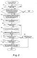
- Figure 2 is a flowchart describing a control process executed in the vehicle cruise control system for setting a cruising speed setting used in a high speed following cruise control mode in accordance with the first embodiment of the present invention
- Figure 3 is a schematic diagram illustrating an example of an image displayed in a display unit of the vehicle cruise control system during a following cruise control in a low speed preceding vehicle following cruise control mode in accordance with the first embodiment of the present invention
- Figure 4 is a schematic diagram illustrating an example of an image displayed in the display unit of the vehicle cruise control system when the cruising speed setting is displayed in accordance with the first embodiment of the present invention
- Figure 5 is a schematic diagram illustrating an example of an image displayed in the display unit of the vehicle cruise control system when the vehicle cruise control system is prepared to shift automatically to a high speed following cruise control mode in accordance with the first embodiment of the present invention
- Figure 6 is a flowchart illustrating a control process executed in a vehicle cruise control system for setting a cruising speed setting used in a high speed following cruise control mode in accordance with a second embodiment of the present invention.
- Figure 7 is a flowchart illustrating a control process executed in a vehicle cruise control system for setting a cruising speed setting used in a prescribed vehicle speed range in accordance with a third embodiment of the present invention.
- a total range of vehicle speeds in which a preceding vehicle following cruise control (i.e., the following cruise control) is executed is divided into two regions, i.e., a low speed region and a high speed region.
- the vehicle cruise control system is configured to selectively execute a following cruise control mode for the low speed region (hereinafter called “low speed following cruise control mode") and a following cruise control mode for the high speed region (hereinafter called “high speed following cruise control mode”) so that the following cruise control is executed in all speed regions of the total range of vehicle speeds.
- total range of vehicle speeds means a substantially entire range of vehicle speeds that ranges from a minimum vehicle speed at which the following cruise control is executed to a maximum vehicle speed at which the following cruise control is executed.
- the minimum vehicle speed of the total range of vehicle speeds is set to 0 km/h or a very low speed (e.g., 10 km/h)
- the maximum vehicle speed of the total range of vehicle speeds is set to a legal speed limit (e.g., 100 km/h) or a higher speed.
- the low speed following cruise control mode is used in the low speed region that ranges from the minimum vehicle speed (e.g., 10 km/h in the first embodiment) of the total range of vehicle speeds to an upper speed limit (e.g., 40 km/h in the first embodiment) for the low speed following cruise control mode.
- the minimum vehicle speed e.g., 10 km/h in the first embodiment
- an upper speed limit e.g., 40 km/h in the first embodiment
- the vehicle cruise control system is configured to execute the preceding vehicle following cruise control such that a vehicle in which the vehicle cruise control system is installed (hereinafter referred as "host vehicle") follows a preceding vehicle while maintaining a preset following distance (second prescribed following distance) when the preceding vehicle is detected in front of the host vehicle, and to abort the preceding vehicle following cruise control if the preceding vehicle ceases to be detected or is not detected in front of the vehicle.
- host vehicle a vehicle in which the vehicle cruise control system is installed
- second prescribed following distance second prescribed following distance
- the high speed following cruise control mode is also called an adaptive cruise control (ACC) mode, and is used in a high speed region that ranges from a lower speed limit (e.g., 40 km/h in the first embodiment) for the high speed following cruise control mode to the maximum vehicle speed (e.g., 110 km/h in the first embodiment) of the total range of vehicle speeds.
- ACC adaptive cruise control
- the vehicle cruise control system is configured to execute the preceding vehicle following cruise control in which one of a constant speed cruise control and the following cruise control is executed depending on whether the preceding vehicle is detected.
- the vehicle cruise control system is configured to execute the constant speed cruise control such that the host vehicle travels in a constant-speed state at a cruising speed that has been set (hereinafter called "cruising speed setting") for the high speed following cruise control mode when the preceding vehicle is not detected in front of the host vehicle, and to execute the following cruise control such that the host vehicle follows the preceding vehicle while maintaining a preset following distance (first prescribed following distance) and not exceeding the cruising speed setting when the preceding vehicle is detected.
- the cruising speed setting is used as an upper speed limit during the following cruise control in the high speed following cruise control mode.
- a driver of the host vehicle can set the cruising speed setting for the high speed following cruise control mode to any desired speed between the lower speed limit (e.g., 40 km/h in the first embodiment) of the high speed following cruise control mode and the maximum vehicle speed (e.g., 110 km/h in the first embodiment) of the total range of vehicle speeds at which the preceding vehicle following cruise control is executed.
- the upper speed limit of the low speed following cruise control mode and the lower speed limit of the high speed following cruise control are both 40 km/h such that the total range of vehicle speeds at which preceding vehicle following cruise control is executed is divided at 40 km/h into two regions, i.e., the high speed region and the low speed region.
- the low speed region can be set to range from 10 to 40 km/h and the high speed region can be set to range from 35 km/h to 110 km/h.
- the total range of vehicle speeds at which the preceding vehicle speed following cruise control is executed is divided into two vehicle speed regions (i.e., the high speed region and the low speed region).
- the total range of vehicle speeds is divided into three or more regions and configure the vehicle cruise control system to execute a unique preceding vehicle following cruise control in each vehicle speed region.
- FIG. 1 is a block diagram illustrating constituent components of the vehicle cruise control system in accordance with the first embodiment.
- the vehicle cruise control system of the first embodiment has a cruise control controller 10 that is operatively coupled to various sensors and switches including a following distance radar 1, a vehicle speed sensor 2, a main switch 3, a resume/accelerate switch 4, a cancel switch 5, a set/coast switch 6 and a brake switch 7.
- the cruise control controller 10 is also operatively coupled to an engine control unit 11, a transmission control unit 12, a brake control unit 13, a display unit 14 and a speaker 15.
- the following distance radar 1 is configured and arranged to sweep a laser beam in front of the host vehicle to detect a preceding vehicle and to detect a distance from the host vehicle to the preceding vehicle (i.e., the following distance).
- a milliwave following distance radar that uses milliwaves can be used for the following distance radar 1 to detect the following distance instead of a laser beam radar.
- the vehicle speed sensor 2 is configured and arranged to detect a traveling speed of the host vehicle.
- the main switch 3 is an operating member for starting the preceding vehicle following cruise control system. When the main switch 3 is on, power is being supplied to the vehicle cruise control system.
- the resume/accelerate switch 4 is an operating member used to resume the preceding vehicle following cruise control at the same cruising speed setting as was previously used or to increase the cruising speed setting. More specifically, if the preceding vehicle following cruise control is not in progress when the resume/accelerate switch 4 is operated, the preceding vehicle following cruise control is resumed using the cruising speed setting for the high speed following cruise control mode that was used the previous time the preceding vehicle following cruise control was executed. On the other hand, if the preceding vehicle following cruise control is in progress when the resume/accelerate switch 4 is operated, the cruising speed setting for the high speed following cruise control mode is increased.
- the cancel switch 5 is an operating member for canceling the preceding vehicle following cruise control.
- the set/coast switch 6 is an operating member used to start the preceding vehicle following cruise control when the preceding vehicle following cruise control is not already in progress and used to reduce the cruising speed setting for the high speed following cruise control mode when the preceding vehicle following cruise control is already in progress.
- the preceding vehicle following cruise control starts if the preceding vehicle is detected and the constant speed cruise control starts if the preceding vehicle is not detected in the high speed region.
- the constant speed cruise control is configured to control the host vehicle to travel at the cruising speed setting for the high speed following cruise control mode.
- the resume/accelerate switch 4, the cancel switch 5, and the set/coast switch 6 are preferably provided on a spoke portion of the steering wheel (not shown) of the host vehicle so that a driver of the host vehicle can operate the resume/accelerate switch 4, the cancel switch 5, and the set/coast switch 6 while sitting on a driver's seat.
- the brake switch 7 is turned on when the brake pedal (not shown) is depressed.
- the cruise control controller 10 preferably includes a microcomputer with the preceding vehicle following cruise control program and the constant speed cruise control program described above to control the vehicle cruise control system as discussed below. More specifically, as seen in Figure 1, the cruise control controller 10 includes a CPU 10a, a ROM (Read Only Memory) 10b, and a RAM (Random Access Memory) 10c. The cruise control controller 10 can also include other conventional components such as an input interface circuit, an output interface circuit, and the like.
- the microcomputer of the cruise control controller 10 is programmed to control the preceding vehicle following cruise control.
- the memory circuit stores processing results and control programs such as ones for the preceding vehicle following cruise control operation that are run by the processor circuit.
- the cruise control controller 10 is operatively coupled to the various sensors and switches in a conventional manner.
- the internal RAM 10c of the cruise control controller 10 stores statuses of operational flags and various control data.
- the internal ROM 10b of the cruise control controller stores the various data and maps for various operations.
- the cruise control controller 10 is capable of selectively controlling any of the components of the vehicle cruise control system in accordance with the control program. It will be apparent to those skilled in the art from this disclosure that the precise structure and algorithms for the cruise control controller 10 can be any combination of hardware and software that will carry out the functions of the present invention. In other words, "means plus function" clauses as utilized in the specification and claims should include any structure or hardware and/or algorithm or software that can be utilized to carry out the function of the "means plus function” clause.
- the engine control unit 11 is configured to execute air intake quantity control, fuel injection control, and ignition timing control of an engine (not shown) to regulate the output torque and the rotational speed of the engine and to control the drive force of the host vehicle.
- the transmission control unit 12 is configured to control the gear ratio, i.e., shift position, of an automatic transmission (not shown) of the host vehicle.
- the brake control unit 13 is configured to control the braking force of the host vehicle by adjusting the brake fluid pressure.
- the display unit 14 is configured and arranged to display the control state of the preceding vehicle following cruise control system and the cruising state of the host vehicle.
- the speaker 15 is configured and arranged to send a voice signal to announce the control state of the preceding vehicle following cruise control system and the cruising state of the host vehicle to the driver.
- the cruise control controller 10 is configured to shift to the preceding vehicle following cruise control in the low speed following cruise control mode unconditionally when the speed of the host vehicle falls to 40 km/h or less while the preceding vehicle following cruise control is executed in the high speed following cruise control mode.
- the cruise control controller 10 is not configured to shift unconditionally to the preceding vehicle following cruise control in the high speed following cruise control mode when the speed of the host vehicle rises to 40 km/h or higher while the preceding vehicle following cruise control is executed in the low speed following cruise control mode. In the latter case, the cruise control controller 10 will not shift automatically unless the cruising speed setting for the high speed following cruise control mode is stored in a prescribed address of the RAM 10c.
- the cruising speed setting for the high speed following cruise control mode can be set or changed even when the host vehicle is traveling in a vehicle speed region other than the high speed region, i.e., outside the vehicle speed region established for the high speed following cruise control.
- the cruising speed setting for the high speed following cruise control mode can be set or changed while the host vehicle is stopped or operating in the low speed following cruise control mode.
- the cruise control controller 10 is configured to shift automatically to the high speed following cruise control mode without any switches (e.g., the resume/accelerate switch 4 or the set/coast switch 6) being operated when the speed of the host vehicle exceeds 40 km/h while the preceding vehicle following cruise control is executed in the low speed following cruise control mode.
- switches e.g., the resume/accelerate switch 4 or the set/coast switch 6
- the cruise control controller 10 of the host vehicle is configured to automatically shift to the high speed following cruise control mode without operating the switches (e.g., the resume/accelerate switch 4 or the set/coast switch 6) and to continue the following cruise control in which the host vehicle follows the preceding vehicle.
- the cruising speed setting for the high speed following cruise control mode can also be set when the vehicle speed is in neither the high speed region nor the low speed region (i.e., the vehicle speed falls outside of a range of speeds at which the preceding vehicle following cruise control is executed) and when the preceding vehicle following cruise control is not being executed.
- the following cruise control that is executed in the high speed following cruise control mode and uses the cruising speed setting can be started immediately by operating the set/coast switch 6 just once.
- the cruising speed setting can be set regardless of the vehicle speed (i.e., at any vehicle speed) when the preceding vehicle following cruise control is not being executed.
- the operation of the vehicle cruise control system in accordance with the first embodiment will now be described with reference to the flowchart of Figure 2.
- the flowchart of Figure 2 describes a control process executed in the cruise control controller 10 for setting the cruising speed setting for the high speed following cruise control mode in accordance with the first embodiment.
- step S 1 of Figure 2 the cruise control controller 10 is configured to check if the resume/accelerate switch 4 has been operated. If the resume/accelerate switch 4 is on in step S1, the cruise control controller 10 is configured to proceed to step S2.
- step S2 the cruise control controller 10 is configured to check if the preceding vehicle following cruise control is currently being executed in the high speed following cruise control mode. If the preceding vehicle following cruise control is in progress in the high speed following cruise control mode, the cruise control controller 10 is configured to end the control sequence. If the vehicle cruise control system is not in the high speed following cruise control mode, the cruise control controller 10 is configured to proceed to step S3.
- step S3 the cruise control controller 10 is configured to set the lower speed limit (40 km/h in the first embodiment) of the high speed cruise control mode as the cruising speed setting for the high speed cruise control mode, and store the cruising speed setting in the prescribed address of the RAM 10c. Then, in step S4, the cruise control controller 10 is configured to send a signal to the display unit 14 to report to the driver that the cruising speed setting for the high speed following cruise control mode has been set.
- Figures 3 to 5 show schematic diagrams of examples of images displayed in the display unit 14 illustrating how the cruise control state and the setting state of the preceding vehicle following cruise control are indicated on the display unit 14.
- the display unit 14 is configured to display an image like that shown in Figure 3.
- the cruising speed setting is displayed as shown in Figure 4 for a prescribed amount of time (e.g., two seconds).
- the display unit 14 is configured to display an indicator like that shown in Figure 5 to indicate that the cruising speed setting for the high speed following cruise control mode is set and the vehicle cruise control system is ready to shift automatically to the high speed following cruise control mode at any time. It is also acceptable to configure the vehicle cruise control system such that the cruise control state, the setting state of the cruising speed setting, and the fact that the system is ready to shift automatically to the high speed following cruise control mode are announced over the speaker 15.
- step S5 the cruise control controller 10 is again configured to check if the resume/accelerate switch 4 has been operated. If the resume/accelerate switch 4 is on, the controller proceeds to step S6. If the resume/accelerate switch 4 is off, the cruise control controller 10 is configured to proceed to step 8. If the resume/accelerate switch 4 has been operated again in step S6, the cruising speed setting for the high speed following cruise control mode is increased. At this time, if the resume/accelerate switch 4 is operated intermittently, the cruising speed setting is increased 5 km/h each time. If the resume/accelerate switch 4 is operated in a continuous manner, the cruising speed setting is increased 5 km/h every two seconds. In step S7, the updated (increased) cruising speed setting is displayed on the display unit 14 as shown in Figure 4 and announced over the speaker 15.
- step S8 the cruise control controller 10 is configured to determine if a prescribed amount of time (e.g., five minutes) has elapsed since the cruising speed setting for the high speed following cruise control mode was set. If the prescribed amount of time has elapsed since the cruising speed setting was set, the cruise control controller 10 is configured to proceed to step S9.
- step S9 the cruise control controller 10 is configured to erase the cruising speed setting from the prescribed address of the RAM 10c because the driver has likely forgotten that he or she set the cruising speed setting and it would not be desirable to automatically shift to the high speed following cruise control mode under such circumstances.
- step S9 the preparation to automatically shift to the high speed following cruise control mode is canceled. When the preparation is canceled, the cruising speed setting indicator displayed on the display unit 14 as shown in Figure 5 disappears and the display on the display unit 14 returns to the state shown in Figure 3.
- step S10 the cruise control controller 10 is configured to check if the current vehicle speed detected by the vehicle speed sensor 2 is in the high speed region (over 40 km/h in the first embodiment). If the vehicle speed is not yet in the high speed region, the cruise control controller 10 is configured to return to step S8 while continuing the following cruise control in the low speed following cruise control mode. On the other hand, if the vehicle speed is in the high speed region in step S10, the cruise control controller 10 is configured to proceed to step S11 and to automatically shift to the high speed following cruise control mode.
- the cruising speed setting for the high speed following cruise control mode can be set or changed even when the system is not executing in the high speed following cruise control mode.
- the host vehicle follows a preceding vehicle in the low speed following cruise control mode, and if the preceding vehicle accelerates beyond the low speed region (i.e., the vehicle speed region in which the low speed following cruise control mode can be used) of the host vehicle, the host vehicle will automatically shift to the high speed following cruise control mode and continue following the preceding vehicle without the driver performing any switch operations.
- the following cruise control that is executed in the high speed following cruise control mode and uses the cruising speed setting can be started immediately by operating the set/coast switch 6 just once.
- the cruising speed setting to be used during the preceding vehicle following cruise control and the constant speed cruise control in the high speed region can be set in advance before the host vehicle actually enters the high speed region.
- the operations required to shift to the high speed following cruise control mode can be simplified.
- the vehicle cruise control system in the second embodiment differs from the vehicle cruise control system of the first embodiment in that the preceding vehicle following cruise control is executed only in a prescribed vehicle speed region in the second embodiment while the vehicle cruise control system of the first embodiment was configured to execute the preceding vehicle following control in the total range of vehicle speeds and a unique preceding vehicle following cruise control was executed in each vehicle speed region. More specifically, in the second embodiment, the vehicle cruise control system is configured to have only the high speed following cruise control mode (ACC following cruise control mode or ACC mode).
- the vehicle cruise control system when the vehicle is traveling in the prescribed vehicle speed region (hereinafter referred as "the ACC vehicle speed region"), the vehicle cruise control system is configured to execute the preceding vehicle following cruise control in which one of a constant speed cruise control and a following cruise control is selectively executed depending on whether a preceding vehicle is detected in front of the host vehicle.
- the vehicle cruise control system is configured to execute the constant speed cruise control such that the host vehicle travels in a constant-speed state at a cruising speed setting (hereinafter referred as "cruising speed setting”) when a preceding vehicle is not detected and to execute the following cruise control such that the host vehicle follows the preceding vehicle while maintaining a following distance and not exceeding the cruising speed setting when the preceding vehicle is detected.
- the ACC vehicle speed region is preferably set to range from 40 km/h to 110 km/h.
- Figure 6 is the flowchart showing a control process executed in the cruise control controller 10 for setting the cruising speed setting for the high speed following cruise control mode in the ACC vehicle speed region in accordance with the second embodiment.
- step S21 of Figure 6 the cruise control controller 10 is configured to check if the resume/accelerate switch 4 has been operated. If the resume/accelerate switch 4 is on in step S21, the cruise control controller 10 is configured to proceed to step S22.
- step S22 the cruise control controller 10 is configured to check if the vehicle speed detected by the vehicle speed sensor 2 is in the ACC vehicle speed region (i.e., in the range between 40 and 110 km/h in the second embodiment). If the current vehicle speed is in the ACC vehicle speed region in step S22, the cruise control controller 10 is configured to end the control sequence. If the current vehicle speed is not in the ACC vehicle speed region in step S22, the cruise control controller 10 is configured to proceed to step S23.
- step S23 the cruise control controller 10 is configured to set the lower speed limit (i.e., 40 km/h in the second embodiment) of the ACC mode as the cruising speed setting, and to store the cruising speed setting in a prescribed address of the RAM 10c. Then, in step S24, the cruise control controller 10 is configured to report or inform to the driver that the cruising speed setting for the ACC mode has been set.
- the lower speed limit i.e., 40 km/h in the second embodiment
- step S25 the cruise control controller 10 is again configured to check if the resume/accelerate switch 4 has been operated. If the resume/accelerate switch 4 is on in step S25, the cruise control controller 10 is configured to proceed to step S26. If the resume/accelerate switch 4 is off in step S25, the cruise control controller 10 is configured to proceed to step S28. If the resume/accelerate switch 4 has been operated again in step S25, the cruising speed setting for the ACC mode is increased in step S26. At this time, if the resume/accelerate switch 4 is operated intermittently, the cruising speed setting is increased 5 km/h each time. If the resume/accelerate switch 4 is operated in a continuous manner, the cruising speed setting is increased 5 km/h every two seconds.
- step S27 the control unit 10 is configured to report to the driver the updated (increased) value of the cruising speed setting and display an indicator on the display unit 14 (as shown in Figure 5) to indicate that the cruising speed setting for the ACC mode is set and the vehicle cruise control system is ready to shift automatically to the ACC mode at any time.
- step S28 the cruise control controller 10 is configured to determine if a prescribed amount of time (e.g., five minutes) has elapsed since the cruising speed setting for the ACC mode was set. If the prescribed amount of time has elapsed since the cruising speed setting was set in step S28, the cruise control controller 10 is configured to proceed to step S29 and to erase the cruising speed setting from the RAM 10c because the driver has likely forgotten that he or she set the cruising speed setting and it would not be desirable to automatically shift to the ACC mode under such circumstances. In short, in step S29 the preparation to automatically shift to the ACC mode is canceled. When the preparation is canceled, the indicator displayed on the display unit 14 to indicate that the vehicle cruise control system is ready to shift automatically to the ACC mode (as shown in Figure 5) disappears.
- a prescribed amount of time e.g., five minutes
- the cruise control controller 10 is configured to proceed to step 30 and to check if the current vehicle speed detected by the vehicle speed sensor 2 is in the ACC vehicle speed region (i.e., over 40 km/h in the second embodiment). If the vehicle speed is not yet in the ACC vehicle speed region in step S30, the cruise control controller 10 is configured to return to step S28. On the other hand, if the vehicle speed is in the ACC vehicle speed region in step S30, the cruise control controller 10 is configured to proceed to step S31 and automatically shifts to the preceding vehicle following cruise control in the ACC mode.
- the cruising speed setting for the ACC mode can be set or changed even when the host vehicle is not traveling in the ACC vehicle speed region.
- the vehicle cruise control system can shift into the ACC mode automatically and commence adaptive cruise control without the driver performing any switch operations.
- the vehicle cruise control system of the third embodiment differs from the vehicle cruise control system of the first embodiment in that the vehicle cruise control system of the third embodiment is arranged as an ASCD (auto speed control device) that is configured to execute a constant speed cruise control such that the host vehicle travels in a constant-speed state at a cruising speed setting (hereinafter called "cruising speed setting") in an ASCD mode regardless of whether or not a preceding vehicle is detected.
- ASCD autonomous speed control device
- the ASCD mode is executed in an ASCD speed region, and the ASCD speed region is preferably set to range from 40 km/h to 110 km/h.
- the constituent components of the third embodiment are the same as those of the first embodiment shown in Figure 1 and descriptions thereof are thus omitted for the sake of brevity.
- the only difference between the structure of the first embodiment and the structure of the third embodiment is that the vehicle cruise control system of the third embodiment does not require the following distance radar 1.
- Figure 7 is the flowchart showing a control process executed in the cruise control controller 10 for setting the cruising speed setting for the ASCD mode in accordance with the third embodiment.
- step S41 the cruise control controller 10 is configured,to check if the resume/accelerate switch 4 has been operated. If the resume/accelerate switch 4 is on in step S41, the cruise control controller 10 is configured to proceed to step S42.
- step S42 the cruise control controller 10 is configured to check if the vehicle speed detected by the vehicle speed sensor 2 is in the ASCD vehicle speed region (i.e., in the range of 40 to 110 km/h in the third embodiment). If the current vehicle speed is in the ASCD vehicle speed region in step S42, the cruise control controller 10 is configured to end the control sequence. If the current vehicle speed is not in the ASCD vehicle speed region in step S42, the cruise control controller 10 is configured to proceed to step S43.
- step S43 the cruise control controller 10 is configured to set the lower speed limit (i.e., 40 km/h in the third embodiment) of the ASCD mode as the cruising speed setting, and to store the cruising speed setting in a prescribed address of the RAM 10c. Then, in step S44, the cruise control controller 10 is configured to report to the driver that the cruising speed setting for the ASCD mode has been set.
- the lower speed limit i.e., 40 km/h in the third embodiment
- step S45 the cruise control controller 10 is again configured to check if the resume/accelerate switch 4 has been operated. If the resume/accelerate switch 4 is on in step S45, the cruise control controller 10 is configured to proceed to step S46. If the resume/accelerate switch 4 is off in step S45, the cruise control controller 10 is configured to proceed to step S48. If the resume/accelerate switch 4 has been operated again in step S45, in step S46 the cruising speed setting for the ASCD mode is increased. At this time, if the resume/accelerate switch 4 is operated intermittently, the cruising speed setting is increased 5 km/h each time. If the resume/accelerate switch 4 is operated in a continuous manner, the cruising speed setting is increased 5 km/h every two seconds.
- step S47 the cruise control controller 10 is configured to report to the driver the updated (increased) value of the cruising speed setting and to display an indicator on the display unit 14 to indicate that the cruising speed setting for the ASCD mode is set and the system is ready to shift automatically to the ASCD mode at any time.
- step S48 the cruise control controller 10 is configured to determine if a prescribed amount of time (e.g., five minutes) has elapsed since the cruising speed setting for the ASCD mode was set. If the prescribed amount of time has elapsed since the cruising speed setting was set in step S48, the cruise control controller 10 is configured to proceed to step S49 and to erase the cruising speed setting from the RAM 10c because the driver has likely forgotten that he or she set the cruising speed setting and it would not be desirable to automatically shift to the ASCD mode under such circumstances. In short, in step S49 the preparation to automatically shift to the ASCD mode is canceled. When the preparation is canceled, the indicator displayed on the display unit 14 to indicate that the vehicle cruise control system is ready to shift automatically to the ASCD mode disappears.
- a prescribed amount of time e.g., five minutes
- the cruise control controller 10 is configured to proceed to step S50 and to check if the current vehicle speed detected by the vehicle speed sensor 2 is in the ASCD vehicle speed region (i.e., over 40 km/h in the third embodiment). If the vehicle speed is not yet in the ASCD vehicle speed region in step S50, the cruise control controller 10 is configured to return to step S48. On the other hand, if the vehicle speed is in the ASCD speed region in step S50, the cruise control controller 10 is configured to proceed to step S51 and to automatically shift to the constant speed cruise control in the ASCD mode.
- the cruising speed setting for the ASCD mode can be set or changed even when the vehicle is not traveling in the ASCD vehicle speed region.
- the vehicle cruise control system can shift into the ASCD mode automatically and commence the constant speed cruise control without the driver performing any switch operations.
- the following distance radar 1 preferably corresponds to the following distance detecting section of the present invention.
- the vehicle speed sensor 2 preferably corresponds to the vehicle speed detecting section of the present invention.
- the cruise control controller 10 preferably corresponds to the cruise control section, the cruising speed setting section, and the cruising speed setting canceling section of the present invention.
- the display unit 14 and the speaker 15 preferably correspond to the reporting section of the present invention.
- the constituent elements of the present invention are not limited to those described herein so long as the characteristic functions of these elements of the present invention are not lost.
- detect as used herein to describe an operation or function carried out by a component, a section, a device or the like includes a component, a section, a device or the like that does not require physical detection, but rather includes determining, measuring, modeling, predicting or computing or the like to carry out the operation or function.
Applications Claiming Priority (1)
| Application Number | Priority Date | Filing Date | Title |
|---|---|---|---|
| JP2004209972A JP2006027457A (ja) | 2004-07-16 | 2004-07-16 | 車両用走行制御装置 |
Publications (2)
| Publication Number | Publication Date |
|---|---|
| EP1616745A1 true EP1616745A1 (de) | 2006-01-18 |
| EP1616745B1 EP1616745B1 (de) | 2012-05-09 |
Family
ID=35058349
Family Applications (1)
| Application Number | Title | Priority Date | Filing Date |
|---|---|---|---|
| EP05015340A Expired - Fee Related EP1616745B1 (de) | 2004-07-16 | 2005-07-14 | Abstands- und Geschwindigkeitsregelsystem |
Country Status (5)
| Country | Link |
|---|---|
| US (1) | US7440835B2 (de) |
| EP (1) | EP1616745B1 (de) |
| JP (1) | JP2006027457A (de) |
| KR (1) | KR100618022B1 (de) |
| CN (1) | CN100476902C (de) |
Cited By (1)
| Publication number | Priority date | Publication date | Assignee | Title |
|---|---|---|---|---|
| CN101425106B (zh) * | 2008-11-06 | 2011-09-14 | 清华大学 | 车辆多目标协调式自适应巡航控制性能的数学量化方法 |
Families Citing this family (32)
| Publication number | Priority date | Publication date | Assignee | Title |
|---|---|---|---|---|
| US6591168B2 (en) * | 2001-08-31 | 2003-07-08 | Intellisist, Inc. | System and method for adaptable mobile user interface |
| US20040084237A1 (en) * | 2002-05-30 | 2004-05-06 | Petrie Alfred E. | Vehicle cruise control system |
| US11267339B2 (en) | 2005-11-17 | 2022-03-08 | Invently Automotive Inc. | Vehicle power management system |
| US11279234B2 (en) | 2005-11-17 | 2022-03-22 | Invently Automotive Inc. | Vehicle power management system |
| US11267338B2 (en) | 2005-11-17 | 2022-03-08 | Invently Automotive Inc. | Electric vehicle power management system |
| US11279233B2 (en) | 2005-11-17 | 2022-03-22 | Invently Automotive Inc. | Electric vehicle power management system |
| JP4497088B2 (ja) * | 2005-12-06 | 2010-07-07 | トヨタ自動車株式会社 | 車速制限制御装置 |
| WO2007102228A1 (ja) * | 2006-03-06 | 2007-09-13 | Hitachi, Ltd. | 自動車の制御装置及び制御方法 |
| US20080138273A1 (en) * | 2006-12-11 | 2008-06-12 | Yi Jiang | Wall flow reactor for hydrogen production |
| DE102006060554A1 (de) * | 2006-12-21 | 2008-06-26 | Bayerische Motoren Werke Ag | Lenkrad für ein Kraftfahrzeug und Kraftfahrzeug |
| US9254749B2 (en) * | 2007-06-07 | 2016-02-09 | GM Global Technology Operations LLC | Cruise control interaction with driver commanded speed reset |
| US8131442B2 (en) * | 2007-11-28 | 2012-03-06 | GM Global Technology Operations LLC | Method for operating a cruise control system for a vehicle |
| KR101168744B1 (ko) | 2008-12-03 | 2012-07-26 | 한국전자통신연구원 | 정속 주행 시스템 및 그 방법 |
| KR101224491B1 (ko) | 2010-02-05 | 2013-01-21 | 정금필 | 어닝 시스템의 프론트바 |
| JP5427202B2 (ja) * | 2011-03-29 | 2014-02-26 | 富士重工業株式会社 | 車両用運転支援装置 |
| DE102011078776A1 (de) * | 2011-07-07 | 2013-01-10 | Robert Bosch Gmbh | Vorrichtung und Verfahren zum Betreiben eines Fahrzeugs |
| KR101316217B1 (ko) | 2011-09-28 | 2013-10-08 | 현대자동차주식회사 | 차량의 연비 및 주행안정성 향상을 위한 공력정보 제공 시스템 및 그 방법 |
| DE102011084606A1 (de) * | 2011-10-17 | 2013-04-18 | Robert Bosch Gmbh | Bestimmung einer Fahrstrategie für ein Fahrzeug |
| US9632666B2 (en) * | 2012-02-16 | 2017-04-25 | GM Global Technology Operations LLC | Team-oriented HVAC system |
| DE102012205263B4 (de) * | 2012-03-30 | 2023-11-23 | Bayerische Motoren Werke Aktiengesellschaft | Geschwindigkeitsregelsystem mit einem berührungssensitiven Bedienelement |
| CN102756732B (zh) * | 2012-07-27 | 2015-08-05 | 浙江吉利汽车研究院有限公司杭州分公司 | 一种车辆的自适应巡航控制系统 |
| CN103015484A (zh) * | 2012-12-12 | 2013-04-03 | 熔盛机械有限公司 | 一种轮胎式液压挖掘机自动巡航系统及其巡航方法 |
| DE102013207539A1 (de) * | 2013-04-25 | 2014-10-30 | Bayerische Motoren Werke Aktiengesellschaft | Geschwindigkeitsregelsystem für Kraftfahrzeuge |
| DE102015001818A1 (de) | 2014-02-19 | 2015-09-03 | Cummins Inc. | Fahrwiderstandsmanagement für Landfahrzeuge und/oder diesbezügliche Bedienerbenachrichtigung |
| US9272621B2 (en) * | 2014-04-24 | 2016-03-01 | Cummins Inc. | Systems and methods for vehicle speed management |
| US9835248B2 (en) | 2014-05-28 | 2017-12-05 | Cummins Inc. | Systems and methods for dynamic gear state and vehicle speed management |
| CN104553798B (zh) * | 2014-11-25 | 2017-04-12 | 奇瑞汽车股份有限公司 | 一种手动变速箱汽车的巡航控制系统及其控制方法 |
| US10246091B2 (en) | 2016-06-13 | 2019-04-02 | Robert Bosch Gmbh | Rear monitoring for automotive cruise control systems |
| CN106843231B (zh) * | 2017-03-24 | 2020-06-16 | 广州汽车集团股份有限公司 | 无人驾驶汽车、无人驾驶汽车的控制方法及其控制装置 |
| US10279808B2 (en) | 2017-05-17 | 2019-05-07 | Bendix Commercial Vehicle Systems Llc | Adaptive cruise control system with speed based mode |
| JP6633663B2 (ja) * | 2018-02-09 | 2020-01-22 | 本田技研工業株式会社 | 車両走行制御装置 |
| JP6695467B1 (ja) * | 2019-03-12 | 2020-05-20 | 三菱電機株式会社 | 車両制御装置 |
Citations (4)
| Publication number | Priority date | Publication date | Assignee | Title |
|---|---|---|---|---|
| EP1075978A2 (de) * | 1999-08-10 | 2001-02-14 | Nissan Motor Company, Limited | Soll-Drehmomenteinstellung für adaptive Geschwindigkeitsregelung eines Fahhrzeugs |
| JP2002234358A (ja) | 2001-02-07 | 2002-08-20 | Honda Motor Co Ltd | 車両用追従走行制御装置 |
| DE10218017A1 (de) * | 2002-04-23 | 2003-11-06 | Bosch Gmbh Robert | Verfahren zur Geschwindigkeits- und Abstandsregelung bei Kraftfahrzeugen |
| DE10254582A1 (de) * | 2002-11-22 | 2004-06-03 | Robert Bosch Gmbh | Geschwindigkeitsregler mit mehreren Betriebsmodi |
Family Cites Families (24)
| Publication number | Priority date | Publication date | Assignee | Title |
|---|---|---|---|---|
| JPS6056638A (ja) * | 1983-09-06 | 1985-04-02 | Aisin Seiki Co Ltd | 定速走行装置 |
| DE3678408D1 (de) * | 1985-12-26 | 1991-05-02 | Toyota Motor Co Ltd | System zur geschwindigkeitsregelung durch einstellung der solleistung und ein verfahren zur regulierung mit phasenvoreilung. |
| JPH01114542A (ja) * | 1987-10-27 | 1989-05-08 | Mazda Motor Corp | 車両の定速走行制御装置 |
| JP2987778B2 (ja) * | 1990-11-30 | 1999-12-06 | アイシン精機株式会社 | 車両速度制御装置 |
| US5839534A (en) * | 1995-03-01 | 1998-11-24 | Eaton Vorad Technologies, Llc | System and method for intelligent cruise control using standard engine control modes |
| SE504467C2 (sv) * | 1995-06-07 | 1997-02-17 | Volvo Ab | Farthållaranordning för motorfordon |
| JP3229215B2 (ja) * | 1996-09-04 | 2001-11-19 | 株式会社日立製作所 | 自動走行装置 |
| JP3799837B2 (ja) * | 1998-10-16 | 2006-07-19 | 株式会社デンソー | クルーズ制御装置用の報知装置 |
| US6161072A (en) * | 1999-01-21 | 2000-12-12 | Intel Corporation | Automatic cruise control |
| DE19924947A1 (de) * | 1999-05-31 | 2000-12-14 | Daimler Chrysler Ag | Verfahren und Vorrichtung zur Begrenzung der Fahrgeschwindigkeit eines Kraftfahrzeugs |
| JP3646660B2 (ja) * | 2001-03-26 | 2005-05-11 | 日産自動車株式会社 | 車両用追従走行制御装置 |
| EP1302356B1 (de) * | 2001-10-15 | 2006-08-02 | Ford Global Technologies, LLC. | Verfahren und Einrichtung zur Steuerung eines Fahrzeuges |
| JP3878008B2 (ja) * | 2001-12-07 | 2007-02-07 | 株式会社日立製作所 | 車両用走行制御装置及び地図情報データ記録媒体 |
| JP2004106708A (ja) * | 2002-09-19 | 2004-04-08 | Nissan Motor Co Ltd | 車両用車速制御装置 |
| US7315569B2 (en) * | 2003-07-11 | 2008-01-01 | Samsung Electronics Co., Ltd. | Method and system for locating a GPS correlated peak signal |
| DE10360776A1 (de) * | 2003-12-23 | 2005-07-28 | Robert Bosch Gmbh | Geschwindigkeitsregler mit Stillstandsfunktion für Kraftfahrzeuge |
| JP3956943B2 (ja) * | 2004-01-27 | 2007-08-08 | 日産自動車株式会社 | 車両用走行制御装置 |
| JP4254586B2 (ja) * | 2004-03-15 | 2009-04-15 | 日産自動車株式会社 | 減速制御装置 |
| US7337056B2 (en) * | 2004-03-29 | 2008-02-26 | Honda Motor Co., Ltd. | Driving control apparatus |
| JP4161938B2 (ja) * | 2004-06-01 | 2008-10-08 | トヨタ自動車株式会社 | 走行制御装置 |
| JP4082388B2 (ja) * | 2004-06-01 | 2008-04-30 | トヨタ自動車株式会社 | 走行制御装置 |
| JP4453468B2 (ja) * | 2004-07-16 | 2010-04-21 | 日産自動車株式会社 | 先行車追従走行制御装置 |
| JP4230432B2 (ja) * | 2004-08-20 | 2009-02-25 | 本田技研工業株式会社 | 車両の走行制御装置 |
| JP4176690B2 (ja) * | 2004-09-03 | 2008-11-05 | 本田技研工業株式会社 | 車両の走行制御装置 |
-
2004
- 2004-07-16 JP JP2004209972A patent/JP2006027457A/ja active Pending
-
2005
- 2005-07-12 US US11/178,412 patent/US7440835B2/en not_active Expired - Fee Related
- 2005-07-14 EP EP05015340A patent/EP1616745B1/de not_active Expired - Fee Related
- 2005-07-15 KR KR1020050064197A patent/KR100618022B1/ko not_active IP Right Cessation
- 2005-07-18 CN CNB200510098034XA patent/CN100476902C/zh not_active Expired - Fee Related
Patent Citations (4)
| Publication number | Priority date | Publication date | Assignee | Title |
|---|---|---|---|---|
| EP1075978A2 (de) * | 1999-08-10 | 2001-02-14 | Nissan Motor Company, Limited | Soll-Drehmomenteinstellung für adaptive Geschwindigkeitsregelung eines Fahhrzeugs |
| JP2002234358A (ja) | 2001-02-07 | 2002-08-20 | Honda Motor Co Ltd | 車両用追従走行制御装置 |
| DE10218017A1 (de) * | 2002-04-23 | 2003-11-06 | Bosch Gmbh Robert | Verfahren zur Geschwindigkeits- und Abstandsregelung bei Kraftfahrzeugen |
| DE10254582A1 (de) * | 2002-11-22 | 2004-06-03 | Robert Bosch Gmbh | Geschwindigkeitsregler mit mehreren Betriebsmodi |
Non-Patent Citations (1)
| Title |
|---|
| PATENT ABSTRACTS OF JAPAN vol. 2002, no. 12 12 December 2002 (2002-12-12) * |
Cited By (1)
| Publication number | Priority date | Publication date | Assignee | Title |
|---|---|---|---|---|
| CN101425106B (zh) * | 2008-11-06 | 2011-09-14 | 清华大学 | 车辆多目标协调式自适应巡航控制性能的数学量化方法 |
Also Published As
| Publication number | Publication date |
|---|---|
| US20060015240A1 (en) | 2006-01-19 |
| EP1616745B1 (de) | 2012-05-09 |
| US7440835B2 (en) | 2008-10-21 |
| KR100618022B1 (ko) | 2006-09-01 |
| KR20060050213A (ko) | 2006-05-19 |
| JP2006027457A (ja) | 2006-02-02 |
| CN100476902C (zh) | 2009-04-08 |
| CN1728191A (zh) | 2006-02-01 |
Similar Documents
| Publication | Publication Date | Title |
|---|---|---|
| EP1616745B1 (de) | Abstands- und Geschwindigkeitsregelsystem | |
| EP1616744B1 (de) | Abstandsbezogenes Fahrgeschwindigkeitsregelsystem | |
| EP3351459B1 (de) | Parkhilfevorrichtung | |
| US6282483B1 (en) | Follow-up cruise control apparatus | |
| EP3424766B1 (de) | Fahrzeugumgebungsanzeigevorrichtung | |
| US6226588B1 (en) | Informing apparatus for cruise control system | |
| JP4333797B2 (ja) | 車両用制御装置 | |
| JP4506568B2 (ja) | 駐車支援装置 | |
| US11667294B2 (en) | Vehicle lane change control apparatus and method | |
| US8744719B2 (en) | Vehicle running control device | |
| US20140032072A1 (en) | Driving support system | |
| US20210213941A1 (en) | Vehicle Control Device | |
| US20140095027A1 (en) | Driving assistance apparatus and driving assistance method | |
| JP3785959B2 (ja) | 車両用走行制御装置 | |
| JP7141470B2 (ja) | 駐車支援装置及び駐車支援方法 | |
| JP2019137316A (ja) | 運転支援装置 | |
| JP4389708B2 (ja) | 車両用表示装置およびその表示方法 | |
| JP5786374B2 (ja) | 運転支援装置及び運転支援方法 | |
| CN111717026B (zh) | 车辆行驶控制装置 | |
| JP2019148248A (ja) | 駆動力制御装置 | |
| JP3633744B2 (ja) | 車両の走行制御装置 | |
| JP4432872B2 (ja) | 車両の走行制御装置 | |
| JP3791306B2 (ja) | 車両用走行制御装置 | |
| JP7213149B2 (ja) | 車両制御装置、車両、車両制御装置の動作方法およびプログラム | |
| JP2006036159A (ja) | 車両の走行制御装置 |
Legal Events
| Date | Code | Title | Description |
|---|---|---|---|
| PUAI | Public reference made under article 153(3) epc to a published international application that has entered the european phase |
Free format text: ORIGINAL CODE: 0009012 |
|
| 17P | Request for examination filed |
Effective date: 20050714 |
|
| AK | Designated contracting states |
Kind code of ref document: A1 Designated state(s): AT BE BG CH CY CZ DE DK EE ES FI FR GB GR HU IE IS IT LI LT LU LV MC NL PL PT RO SE SI SK TR |
|
| AX | Request for extension of the european patent |
Extension state: AL BA HR MK YU |
|
| AKX | Designation fees paid |
Designated state(s): DE FR GB |
|
| GRAP | Despatch of communication of intention to grant a patent |
Free format text: ORIGINAL CODE: EPIDOSNIGR1 |
|
| GRAS | Grant fee paid |
Free format text: ORIGINAL CODE: EPIDOSNIGR3 |
|
| GRAA | (expected) grant |
Free format text: ORIGINAL CODE: 0009210 |
|
| AK | Designated contracting states |
Kind code of ref document: B1 Designated state(s): DE FR GB |
|
| REG | Reference to a national code |
Ref country code: GB Ref legal event code: FG4D |
|
| REG | Reference to a national code |
Ref country code: DE Ref legal event code: R096 Ref document number: 602005034066 Country of ref document: DE Effective date: 20120705 |
|
| PLBE | No opposition filed within time limit |
Free format text: ORIGINAL CODE: 0009261 |
|
| STAA | Information on the status of an ep patent application or granted ep patent |
Free format text: STATUS: NO OPPOSITION FILED WITHIN TIME LIMIT |
|
| 26N | No opposition filed |
Effective date: 20130212 |
|
| REG | Reference to a national code |
Ref country code: DE Ref legal event code: R097 Ref document number: 602005034066 Country of ref document: DE Effective date: 20130212 |
|
| REG | Reference to a national code |
Ref country code: FR Ref legal event code: PLFP Year of fee payment: 11 |
|
| PGFP | Annual fee paid to national office [announced via postgrant information from national office to epo] |
Ref country code: GB Payment date: 20150708 Year of fee payment: 11 Ref country code: DE Payment date: 20150707 Year of fee payment: 11 |
|
| PGFP | Annual fee paid to national office [announced via postgrant information from national office to epo] |
Ref country code: FR Payment date: 20150629 Year of fee payment: 11 |
|
| REG | Reference to a national code |
Ref country code: DE Ref legal event code: R119 Ref document number: 602005034066 Country of ref document: DE |
|
| GBPC | Gb: european patent ceased through non-payment of renewal fee |
Effective date: 20160714 |
|
| PG25 | Lapsed in a contracting state [announced via postgrant information from national office to epo] |
Ref country code: FR Free format text: LAPSE BECAUSE OF NON-PAYMENT OF DUE FEES Effective date: 20160801 Ref country code: DE Free format text: LAPSE BECAUSE OF NON-PAYMENT OF DUE FEES Effective date: 20170201 |
|
| REG | Reference to a national code |
Ref country code: FR Ref legal event code: ST Effective date: 20170331 |
|
| PG25 | Lapsed in a contracting state [announced via postgrant information from national office to epo] |
Ref country code: GB Free format text: LAPSE BECAUSE OF NON-PAYMENT OF DUE FEES Effective date: 20160714 |