EP1615723B1 - Dispositif de broyage - Google Patents
Dispositif de broyage Download PDFInfo
- Publication number
- EP1615723B1 EP1615723B1 EP04719949A EP04719949A EP1615723B1 EP 1615723 B1 EP1615723 B1 EP 1615723B1 EP 04719949 A EP04719949 A EP 04719949A EP 04719949 A EP04719949 A EP 04719949A EP 1615723 B1 EP1615723 B1 EP 1615723B1
- Authority
- EP
- European Patent Office
- Prior art keywords
- discharge conveyor
- support structure
- unit
- conveyor unit
- crusher
- Prior art date
- Legal status (The legal status is an assumption and is not a legal conclusion. Google has not performed a legal analysis and makes no representation as to the accuracy of the status listed.)
- Expired - Lifetime
Links
- 238000000034 method Methods 0.000 claims abstract description 5
- 238000005065 mining Methods 0.000 claims abstract description 3
- 238000004064 recycling Methods 0.000 claims abstract 2
- 239000000463 material Substances 0.000 claims description 2
- 238000012423 maintenance Methods 0.000 description 5
- XEEYBQQBJWHFJM-UHFFFAOYSA-N Iron Chemical compound [Fe] XEEYBQQBJWHFJM-UHFFFAOYSA-N 0.000 description 4
- 238000013461 design Methods 0.000 description 4
- 238000012546 transfer Methods 0.000 description 4
- 229910052742 iron Inorganic materials 0.000 description 2
- 239000011435 rock Substances 0.000 description 2
- 238000012549 training Methods 0.000 description 2
- 230000001960 triggered effect Effects 0.000 description 2
- RYGMFSIKBFXOCR-UHFFFAOYSA-N Copper Chemical compound [Cu] RYGMFSIKBFXOCR-UHFFFAOYSA-N 0.000 description 1
- 235000019738 Limestone Nutrition 0.000 description 1
- WYTGDNHDOZPMIW-RCBQFDQVSA-N alstonine Natural products C1=CC2=C3C=CC=CC3=NC2=C2N1C[C@H]1[C@H](C)OC=C(C(=O)OC)[C@H]1C2 WYTGDNHDOZPMIW-RCBQFDQVSA-N 0.000 description 1
- 230000000712 assembly Effects 0.000 description 1
- 238000000429 assembly Methods 0.000 description 1
- 239000004927 clay Substances 0.000 description 1
- 239000003245 coal Substances 0.000 description 1
- 239000000470 constituent Substances 0.000 description 1
- 229910052802 copper Inorganic materials 0.000 description 1
- 239000010949 copper Substances 0.000 description 1
- 238000011161 development Methods 0.000 description 1
- 238000010586 diagram Methods 0.000 description 1
- 230000000694 effects Effects 0.000 description 1
- 238000005265 energy consumption Methods 0.000 description 1
- 238000000605 extraction Methods 0.000 description 1
- PCHJSUWPFVWCPO-UHFFFAOYSA-N gold Chemical compound [Au] PCHJSUWPFVWCPO-UHFFFAOYSA-N 0.000 description 1
- 229910052737 gold Inorganic materials 0.000 description 1
- 239000010931 gold Substances 0.000 description 1
- 239000010438 granite Substances 0.000 description 1
- 239000010440 gypsum Substances 0.000 description 1
- 229910052602 gypsum Inorganic materials 0.000 description 1
- 238000009434 installation Methods 0.000 description 1
- 239000006028 limestone Substances 0.000 description 1
- -1 marl Substances 0.000 description 1
- 239000004058 oil shale Substances 0.000 description 1
- 239000000758 substrate Substances 0.000 description 1
- 239000000725 suspension Substances 0.000 description 1
Images


Classifications
-
- B—PERFORMING OPERATIONS; TRANSPORTING
- B02—CRUSHING, PULVERISING, OR DISINTEGRATING; PREPARATORY TREATMENT OF GRAIN FOR MILLING
- B02C—CRUSHING, PULVERISING, OR DISINTEGRATING IN GENERAL; MILLING GRAIN
- B02C21/00—Disintegrating plant with or without drying of the material
- B02C21/02—Transportable disintegrating plant
Definitions
- the invention relates to a crushing device, according to the preamble of claim 1.
- Crushing devices of the type mentioned are used to lumpy crushing material, such as ores (iron ore, brown iron ore, copper ore, gold ore), rocks (granite, rock, gypsum, serpentine, limestone), hard coal, oil shale, marl, clay and .Abraum to a desired to reduce specified grain size.
- hammer crushers, impact crushers, roll crushers, cone crushers, jaw crushers or gyratory crushers are used in particular as crusher devices.
- the required with regard to the mining progress mobility of the crushing devices is thereby ensured that the support structure is equipped with crawler tracks, wheeled or walking gears.
- Semimobile comminution devices are designed such that they can be displaced in the desired manner by means of independent transport means, in particular by means of transporting caterpillars.
- the discharge conveyor consists only of a respect to the support structure non-adjustable discharge conveyor. Accordingly, the crushing device can be adapted to changing working conditions only by, if necessary, displacing the crushing device as a unit itself and / or using additional transporting means which cooperate with the relatively stationary discharge conveyor.
- From the AT 388 968 B is a portable crushing known, which can be pivoted on a crawler undercarriage, a downstream conveyor about a horizontal axis in the vertical direction and about a substantially vertical axis in the horizontal direction.
- the invention has for its object to design a crushing device of the type mentioned in such a way that their efficiency is increased, in particular by reducing the need for maintenance and improved adaptability to different working conditions.
- the novel shredding device should also take into account the viewpoint that relevant mobile or semi-mobile units must be designed as "light" as possible because of limited ground pressures.
- the object is achieved by a crushing device with the features of claim 1.
- the basic idea is therefore to reconstruct the breaker device only a single discharge conveyor unit, which is used for both the trigger and for the ejection process and the is formed pivotable with respect to the support structure as an assembly in the horizontal and in the vertical direction.
- the novel crushing device according to the "two-conveyor system" is formed, wherein the discharge conveyor unit can be both swung laterally as an assembly and is adjustable in height.
- the loading conveyor as well as the discharge conveyor unit can be designed to be arbitrary, in particular as a plate belt, chain conveyor or webbing.
- the pivoting movements of the discharge conveyor unit can be triggered by means of any drives, in particular by means of hydraulic or electromechanical drive means.
- the discharge conveyor unit is designed such that it can be pivoted during the comminution process (that is, when the crusher device is in operation) (claim 2). This presupposes that the crushing product emerging from the crusher device is fed to the transfer section of the discharge conveyor unit without interference - regardless of its operating position and pivoting movements.
- the discharge conveyor unit is laterally pivotable about a horizontal movement axis of rotation, whose position is adapted to that of the crusher outlet.
- the object of the invention is further developed in that the discharge conveyor unit - starting from their straight position, in which it is aligned parallel to the longitudinal extent of the support structure - in the horizontal direction in each case by up to 120 ° in a clockwise or counterclockwise direction can be pivoted (claim 3 ).
- the discharge conveyor should be designed in the invention in such a way that - starting from its horizontal position in which it is aligned parallel to a horizontal reference plane of the support structure - in an angular range between 30 ° with respect to the horizontal reference plane can be pivoted downwards and 20 ° with respect to the horizontal reference plane down (claim 4).
- a horizontal reference plane a suitable plane can be selected, which is determined by the structure of the crushing device.
- the transverse plane can be selected, which runs perpendicular to the longitudinal axis of the breaker device;
- the crushing device should be designed in principle such that the breaker device - and thus the adjacent transfer section of the discharge conveyor unit - seen in the longitudinal direction of the support structure with respect to this an eccentric or asymmetric position occupies.
- the crushing device is formed such that the breaking device as well as the horizontal movement axis of rotation of the discharge conveyor unit for the horizontal movement on the - viewed in the longitudinal direction of the support structure - from the hopper (feed hopper) side facing away in the last third to last quarter of the longitudinal extension of Supporting structure is arranged (claim 5).
- the breaker device on the - viewed in the longitudinal direction of the support structure - facing away from the hopper side be attached to a cantilever, which extends at a distance above the support elements, via which the supporting structure is supported on the ground.
- the discharge conveyor unit is designed pivotable below the cantilever (claim 6).
- the support elements are formed by a chassis or walking gear or by sitting on the ground legs.
- the discharge conveyor unit according to the invention can either be suspended below the cantilever at this or be stored below the cantilever on another component of the support structure.
- a further advantageous embodiment of the subject invention is characterized in that the breaker device and the discharge conveyor unit holding pivot connection are arranged such that the crusher axis, in the region of which is also the horizontal axis of rotation of the discharge conveyor unit, from the feed container in the longitudinal direction of Supporting structure and seen in the direction of the breaker device behind the support elements over which the support structure is supported on the ground (claim 7).
- the breaker device and the pivot connection of the discharge conveyor unit on the side facing away from the loading container (loading bunker) side are displaced outwards so that they are outside the range of support elements for the support structure.
- the advantage thus achieved is, in particular, that the breaker device and the discharge conveyor unit are dimensionally independent of the design of the support elements; Furthermore, the area in which the discharge conveyor unit is held on the support structure, as well as the exit area of the breaker device for repair and maintenance purposes is easily accessible.
- the subject of the invention can also be further developed in that the support structure - seen in the direction of its longitudinal extension - on the side facing away from the feed container side has a component in the form of a "U" with horizontal legs and away from the feed container leg opening.
- the breaker device is arranged on the upper leg, while the discharge conveyor unit is pivotally mounted below the breaker device in the region of the leg opening.
- the U-shaped component makes it possible to pivotally suspend the discharge conveyor unit either on the upper leg or support it on the lower leg.
- the use of the subject in question Part of this is advantageous insofar as the defined by the two legs and the connecting web space both from both sides and the front side (that is, from the opposite side of the feed container) is accessible.
- the support structure has - viewed in the direction of its longitudinal extent - on the side facing away from the feed container side a U-shaped component with horizontal legs and away from the feed container opening, wherein the U-shaped component is arranged at a distance above the support elements, over which the supporting structure is supported on the ground.
- a guide frame is held, which can be pivoted about a horizontal movement axis of rotation.
- the discharge conveyor unit is adjustable in height with respect to the guide frame and tracked with its pivoting movement.
- the variant addressed here thus has, as an additional adjusting element, a guide frame which can be swiveled in the horizontal direction.
- the discharge conveyor unit in such a way that they can be moved on the one hand in the horizontal direction and on the other hand can be raised or lowered relative to the guide frame.
- the guide frame is designed such that it engages around the U-shaped component of the support structure from the outside, that is, that it is supported at the same time on the one leg above the upper leg and on the other hand below the lower leg on the respective leg.
- an open frame can be dispensed with the use of a Rieselgut-catcher in the relevant section of the support structure, which is normally arranged to protect the underlying environment below the feed conveyor.
- optional devices for example, drive elements, control elements, power supply devices
- the crushing device can be retrofitted with a Rieselgut-catcher - in the simplest case in the form of a gutter held below the feed conveyor - can be equipped.
- the comminution apparatus generally designated 1 has the following main components: a hopper (or hopper) 2, a feed conveyor in the form of a conveyor belt 3, a support structure 4 supported by a crawler track 5 on the ground 6, a breaker means in the form of a two-roll crusher 7, and designed as a conveyor discharge conveyor unit 8.
- the support structure 4 is on the feed container 2 side facing - like FIG. 2 can recognize - formed as an open frame, which is composed of two spaced-apart longitudinal members 4a and 4b and a cross member 4c connecting them together.
- the conveyor belt housing 3a of the conveyor belt 3 is held on the support structure 4 via a bearing 4d.
- the supporting structure 4 On the side facing away from the charging container 2 side (ie in FIG. 3 right), the supporting structure 4 has a U-shaped component 4e. This sits down - seen in side view - from two horizontal legs 4f and 4g with facing away from the hopper 2 opening and a connecting web 4h together.
- the upper leg 4f is connected on the feed container 2 side facing at least one support rod 9 with the cross member 4c.
- the two-roll crusher 7 is arranged at a distance above the discharge conveyor unit 8, which in turn is in the horizontal and vertical direction pivotally connected to the lower leg 4g of the U-shaped component 4e in combination.
- the discharge conveyor unit 8 is articulated via a (perpendicular to the plane of the drawing) vertical axis of movement 10 to a rotary console 11, which in turn about the longitudinal axis 7a of the two-roller crusher 7 pivotally relative to the lower leg 4g can be moved.
- FIG. 1 can recognize the discharge conveyor unit 8 - starting from its horizontal position in which it is aligned parallel to a horizontal reference plane (for example, to the transverse plane to the longitudinal axis 7a) of the support structure 4 - are pivoted about the vertical axis of movement 10 in the counterclockwise direction; in the illustrated pivot position 8 ', the achieved pivot angle is 12 °.
- the rotary console 11 makes it possible to pivot the discharge conveyor unit 8 with respect to the support structure 4 in the horizontal direction.
- FIG. 2 shows a pivot position 8 "of the discharge conveyor unit 8, which - has been achieved by a pivoting movement in the clockwise direction by 75 °, starting from the straight position in which the discharge conveyor unit is aligned parallel to the longitudinal extent of the supporting structure 4,
- additional devices 12a to 12c are each arranged laterally next to the longitudinal members 4a and 4b. Accordingly, in the region of the conveyor belt 3 accumulating Rieselgut practically unhindered emerge downwards, so that - like FIG. 1 can be seen - can be dispensed with the use of a Rieselgut-catcher below the conveyor belt 3.
- FIG. 1 can also be seen that the two-roll crusher 7 and the pivotal connection of the discharge conveyor 8 on the side facing away from the hopper 2 side about the last quarter of the longitudinal extension of the support structure 4 are arranged, with the result that the area between the double roller crusher 7 and the lower leg 4g with the turntable console 11, especially for maintenance purposes, is easily accessible.
- the two-roll crusher 7 is equipped in the direction of the discharge conveyor unit 8 in a conventional manner with an outlet funnel 7 b, the more or less far into a trough-shaped transfer section 8a of the discharge conveyor unit 8 protrudes.
- the shredded product obtained by means of the two-roll crusher 7 passes through the interposition of the parts 7b and 8a on the discharge conveyor unit 8 and can be transferred by means of this to a conveyor belt 13 we defectss.
- a driver's cab 15 is formed on support elements 14 of no interest here.
- the range of motion of the discharge conveyor unit 8 by suitable design and arrangement of the parts 10 and 11 can be extended such that the discharge conveyor unit 8 - starting from the in FIG. 1 shown horizontal position - with respect to the support structure 4 can also be pivoted downwards. Moreover, the discharge conveyor unit 8 - starting from the in FIG. 2 straight position shown - also in the counterclockwise direction (that is, in the illustration above) to be moved.
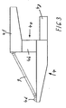
- the FIG. 4 and 5 illustrated embodiment of the crushing device is equipped with a multi-track chassis 16, the three pairs of tracks 16a are pivotally supported on a landing gear platform 16b. On this, the support structure 4 is movably supported via a rotary joint 16c.
- the support structure 4 - seen in the direction of its longitudinal extent - on the side facing away from the feed container 2 side with an angled upward in this direction cantilever 4i, the far protrudes (in the illustration to the right) on the multi-track suspension 16 and on which a breaker device in the form of a two-roll crusher 7 is attached.
- the two-roller crusher 7 assumes with respect to the multi-track chassis 16 a position in which the crusher axis 7a - on the side facing away from the feed container 2 side of the crushing device 1 - at a distance in front of the two front pairs of tracks 16;
- FIG. 4 can still be removed, the support structure 4 - seen from the hopper 2 from lying in front of the two-roll crusher 7 - equipped with an angle arm 4k; the components 4i and 4k together again form a laterally open, approximately U-shaped component with a front-side opening directed away from the charging container 2, in which the two-roller crusher 7 is arranged.
- a guide frame 17 is pivotally mounted in the horizontal direction on the angle arm 4k or the cantilever 4i, whose frame axis 17a coincides with the crusher axis 7a.
- the discharge conveyor unit 8 is held vertically adjustable about a vertical axis of movement 10 via a rotary console 11.
- the discharge conveyor unit is equipped on both sides with articulated guide rods 18; these are in turn connected to retractable and extendable cylinder assemblies 19, which are held above the angle arm 4k hinged to the guide frame 17.
- retractable and extendable cylinder assemblies 19 By retracting or extending the cylinder units 19, the height position of the discharge conveyor unit with respect to the guide frame 17 can be changed continuously.
- FIG. 4 two different height positions of the discharge conveyor unit with respect to a horizontal reference plane 20 are shown. In the height position designated 8 ', the discharge conveyor unit is pivoted upwards by about 10 °; in contrast, takes the discharge conveyor unit in the designated 8 '"height position a pivoted by about 10 ° down position.
- the horizontal reference plane is aligned in the illustrated embodiment, parallel to the plane of the rotary joint 16 c, via which the support structure 4 is held movable with respect to the multi-track chassis 16.
- the outlet funnel 7b of the two-roller crusher 7 passes below the cantilever 4i into a transfer head 7c, which is likewise held pivotably on the cantilever 4i about the crusher axis 7a.
- the crushing device 1 (as in FIG. 4 indicated) additionally be equipped or retrofitted with a channel-like Rieselgut-catcher 21, which extends below the conveyor belt 3 in the region between the feed container 2 and the two-roll crusher 7.
- the Rieselgut-catching device is supported on the one hand in the vicinity of the feed container 2 via a support 21a on the substrate 6 and on the other hand held in the vicinity of the two-roll crusher 7.
- FIG. 5 shows, on the one hand, the position and mutual association of the three caterpillar pairs 16a forming the multi-track chassis 16 and the position of the pivot 16d of the rotary joint 16c.
- the advantage of the embodiment according to FIG. 4 and 5 is to be seen in the fact that the discharge conveyor unit 8 is arranged with its connection to the support structure 4 completely outside the range of the multi-track chassis 16 and thus easily accessible for repair and maintenance purposes.
- the range of motion of the discharge conveyor unit 8 - with respect to the already mentioned "off-center" arrangement on the support structure 4 - are designed to be relatively large in the vertical direction, thereby increasing the scope and cost of the crushing device 1 accordingly.
- FIG. 6 illustrated embodiment differs from the previously explained embodiment that no guide frame is present. Instead, the discharge conveyor unit 8 is held above the two-roller crusher 7 on a cylinder unit 21 which can be moved on the one hand about a vertical axis 21b and on the other hand about a (not shown, aligned perpendicular to the plane) horizontal axis 21c.
- the vertical axis 21b coincides in the illustrated embodiment with the crusher axis 7a.
- the cylinder unit 21 is articulated via its retractable and extendable piston rod 21a with a cross member 22a in connection. From this go on both sides of the discharge conveyor unit 8 hinged push rods 22 and cable tension 23a and 23b.
- the holding in question of the discharge conveyor unit is thus designed such that the latter - starting from a horizontal reference plane 20 - raised by retracting the cylinder unit 21 in the height position designated 8 'or by extending into the 8'"designated height position can be lowered. With the retraction and extension of the cylinder unit this is simultaneously pivoted about the horizontal axis 21c.
- the vertical axis 21b makes it possible to move the discharge conveyor unit relative to the support structure 4 into and out of the plane of the drawing, the cylinder unit 21, under the effect of the components 22, 22a, 23a and 23b, of the pivoting movement of the discharge conveyor unit 8 about the vertical axis 21b is tracked.
- the solution according to the invention is basically applicable regardless of how the breaker device, the feed conveyor, the discharge conveyor unit and the facilities used for operation as a mobile or semi-mobile unit are otherwise provided.
- the feed conveyor and the discharge conveyor unit - if necessary, also deviating from each other - be designed as a plate belt, chain conveyor or webbing.
Claims (8)
- Dispositif de broyage, configuré comme unité mobile ou semi-mobile (1), en particulier pour usage dans les mines à ciel ouvert et dans l'industrie de recyclage, avec un bac de chargement (2), une unité de chargement et convoyage (3) située en aval du bac de chargement (2), pour une unité de concassage (7), un dispositif d'évacuation et convoyage servant au transport du produit broyé dans ladite unité de concassage et une construction support (4) sur laquelle sont fixés les composants mentionnés précédemment, ledit dispositif d'évacuation et convoyage étant constitué d'une seule unité d'évacuation et convoyage (8) utilisée aussi bien pour l'extraction que pour l'évacuation, ladite unité étant configurée comme sous-groupe pouvant être pivoté horizontalement et verticalement par rapport à la construction support (4), caractérisé en ce que la construction support (4) - vu dans le sens de son extension longitudinale - présente du côté opposé au bac d'alimentation (2) un composant (4e) en forme de « U » avec des ailes horizontales (4f, 4g) et une ouverture d'aile opposée au bac d'alimentation (2) ; que l'unité de concassage (7) est située sur l'aile supérieure (4f) et que l'unité d'évacuation et convoyage (8) est logée sous l'unité de concassage (7) au niveau de l'ouverture d'aile sur l'aile inférieure (4g) de manière à permettre un pivotement autour d'un axe de rotation horizontal (10) et d'un axe de rotation vertical (7a).
- Dispositif selon la revendication 1, caractérisé en ce que l'unité d'évacuation et convoyage (8) est configurée de manière telle qu'elle peut être pivotée pendant l'opération de broyage.
- Dispositif selon l'une des revendications précédentes, caractérisé en ce que l'unité d'évacuation et convoyage (8) - en partant de la position droite dans laquelle elle est alignée parallèlement à l'extension longitudinale de la construction support (4) - peut être pivotée dans le sens horizontal jusqu'à 120° en sens horaire et en sens antihoraire.
- Dispositif selon l'une des revendications précédentes, caractérisé en ce que l'unité d'évacuation et convoyage (8) - en partant de la position horizontale dans laquelle elle se déploie parallèlement par rapport à un plan de référence horizontal (20) de la construction support (4) - peut être pivotée vers le haut dans un champ angulaire entre 30° par rapport au plan de référence horizontal (20) et vers le bas dans un champ angulaire entre 20° par rapport au plan de référence horizontal (20).
- Dispositif selon l'une des revendications précédentes, caractérisé en ce que l'unité de concassage (7) est située tout comme l'axe de rotation horizontal (17a) de l'unité d'évacuation et convoyage (8) pour le mouvement horizontal de ladite unité - vu dans le sens longitudinal de la construction support (4) - sur le côté opposé au bac de chargement (2) dans le dernier tiers jusqu'au dernier quart de l'extension longitudinale de la construction support (4).
- Dispositif selon l'une des revendications précédentes, caractérisé en ce que l'unité de concassage (7) est fixée - vu dans le sens longitudinal de la construction support (4) - à un bras en porte-à-faux situé sur le côté opposé au bac de chargement (2), ledit bras en porte-à-faux (4f) se déployant à distance au-dessus des éléments support (5) par l'intermédiaire desquels la construction support (4) prend appui au sol (6), et que l'unité d'évacuation et convoyage (8) est configurée au-dessous du bras en porte-à-faux (4f) de manière à pouvoir être pivotée.
- Dispositif selon l'une des revendications précédentes, caractérisé en ce que l'unité de concassage (7) et l'articulation portant l'unité d'évacuation et convoyage (8) sont configurées de manière telle que l'axe du concasseur (7a) dans la zone duquel se trouve également l'axe de rotation horizontal (17a) de l'unité d'évacuation et convoyage (8) est situé - vu du bac de chargement (2) dans le sens longitudinal de la construction support (4) et vers l'unité de concassage (7) - derrière les éléments support (16a) par l'intermédiaire desquels la construction support (4) prend appui au sol (6).
- Dispositif selon l'une des revendications précédentes, caractérisé en ce que la construction support (4) est configurée comme cadre ouvert avec des poutres longitudinales (4a, 4b) espacées latéralement l'une de l'autre sur le côté opposé au bac de chargement (2) sur une partie considérable de son extension longitudinale, au moins dans un ordre de grandeur de 40%, entre le bac de chargement (2) et la section d'extrémité de l'unité de chargement et convoyage (3) côté concasseur.
Priority Applications (1)
| Application Number | Priority Date | Filing Date | Title |
|---|---|---|---|
| PL04719949T PL1615723T3 (pl) | 2003-04-02 | 2004-03-12 | Urządzenie rozdrabniające |
Applications Claiming Priority (2)
| Application Number | Priority Date | Filing Date | Title |
|---|---|---|---|
| DE10314958A DE10314958A1 (de) | 2003-04-02 | 2003-04-02 | Zerkleinerungsvorrichtung |
| PCT/EP2004/002572 WO2004087324A1 (fr) | 2003-04-02 | 2004-03-12 | Dispositif de broyage |
Publications (2)
| Publication Number | Publication Date |
|---|---|
| EP1615723A1 EP1615723A1 (fr) | 2006-01-18 |
| EP1615723B1 true EP1615723B1 (fr) | 2008-06-25 |
Family
ID=33103174
Family Applications (1)
| Application Number | Title | Priority Date | Filing Date |
|---|---|---|---|
| EP04719949A Expired - Lifetime EP1615723B1 (fr) | 2003-04-02 | 2004-03-12 | Dispositif de broyage |
Country Status (10)
| Country | Link |
|---|---|
| US (1) | US7182284B2 (fr) |
| EP (1) | EP1615723B1 (fr) |
| CN (1) | CN100363110C (fr) |
| AT (1) | ATE399059T1 (fr) |
| BR (1) | BRPI0408898B1 (fr) |
| CA (1) | CA2512742C (fr) |
| DE (2) | DE10314958A1 (fr) |
| PL (1) | PL1615723T3 (fr) |
| RU (1) | RU2327522C2 (fr) |
| WO (1) | WO2004087324A1 (fr) |
Cited By (4)
| Publication number | Priority date | Publication date | Assignee | Title |
|---|---|---|---|---|
| WO2010130324A1 (fr) * | 2009-05-13 | 2010-11-18 | ThyssenKrupp Fördertechnik GmbH | Installation de concassage entièrement mobile, au moyen d'un dispositif à châssis sur chenilles |
| DE102009021167A1 (de) | 2009-05-13 | 2010-11-18 | ThyssenKrupp Fördertechnik GmbH | Mobile Brechanlage |
| DE102011000015A1 (de) | 2011-01-03 | 2012-07-05 | ThyssenKrupp Fördertechnik GmbH | Mobile Brechanlage |
| EP4344785A1 (fr) | 2022-09-29 | 2024-04-03 | SBM Mineral Processing GmbH | Dispositif de traitement |
Families Citing this family (34)
| Publication number | Priority date | Publication date | Assignee | Title |
|---|---|---|---|---|
| GB0408594D0 (en) * | 2004-04-16 | 2004-05-19 | Extec Screens & Crushers Ltd | Crusher apparatus |
| US8025140B2 (en) * | 2005-12-09 | 2011-09-27 | Metso Minerals Inc. | Material processing apparatus comprising a conveyor |
| DE102007039766A1 (de) * | 2006-09-11 | 2008-03-27 | ThyssenKrupp Fördertechnik GmbH | Mobile Brecheranlage |
| AP2011005660A0 (en) * | 2008-09-17 | 2011-04-30 | Flsmidth Rahco Inc | Mobile crushing station. |
| AT507654B1 (de) * | 2008-12-03 | 2011-06-15 | Sandvik Mining & Constr Oy | Fahrbare brecheranlage |
| DE102008060459A1 (de) * | 2008-12-05 | 2010-06-10 | ThyssenKrupp Fördertechnik GmbH | Mobile Brechanlage |
| DE102009016405A1 (de) | 2009-02-09 | 2010-09-02 | Takraf Gmbh | Mobilbrecher |
| DE102010013154A1 (de) | 2009-04-04 | 2010-12-30 | Takraf Gmbh | Mobilbrecher |
| US8789784B2 (en) * | 2010-05-14 | 2014-07-29 | Ange Construction Co. | Mobile self-contained loading and crushing apparatus |
| EP2637793A1 (fr) * | 2010-11-08 | 2013-09-18 | FLSmidth A/S | Station de calibrage mobile |
| EP2977107B1 (fr) * | 2011-02-15 | 2017-06-14 | Metso Minerals, Inc. | Dispositif de traitement mobile pour le traitement d'un matériau minéral |
| CN102837948B (zh) * | 2012-09-18 | 2015-04-15 | 华电重工股份有限公司 | 一种移置式带式输送机机头站及其使用方法 |
| CN102950059B (zh) * | 2012-10-15 | 2015-10-28 | 三一重型装备有限公司 | 一种破碎站 |
| CN103008086A (zh) * | 2012-11-28 | 2013-04-03 | 三一重型装备有限公司 | 移动破碎设备 |
| GB2510839B (en) * | 2013-02-14 | 2017-11-01 | Terex Gb Ltd | Material Processing Apparatus with Multi-mode Feed Conveyor Assembly |
| DE102013208351B4 (de) * | 2013-05-07 | 2018-01-04 | Takraf Gmbh | Mobile Brecheranlage mit variabler Schrägstellung |
| EP2837583B1 (fr) * | 2013-08-14 | 2015-10-14 | Sandvik Intellectual Property AB | Appareil mobile de traitement de matériaux en vrac avec transporteur à giration |
| CN103433111B (zh) * | 2013-08-22 | 2015-12-02 | 天地(唐山)矿业科技有限公司 | 自移式破碎机 |
| US9376260B2 (en) * | 2014-02-06 | 2016-06-28 | Metso Minerals, Inc. | Conveyor body and mobile mineral material processing plant |
| CN104261085B (zh) * | 2014-10-30 | 2016-08-24 | 徐州徐工施维英机械有限公司 | 带式输送机及移动破碎筛分设备 |
| WO2016095958A1 (fr) | 2014-12-16 | 2016-06-23 | Sandvik Intellectual Property Ab | Broyeur à entraînement multiple |
| CN104475219A (zh) * | 2014-12-17 | 2015-04-01 | 新乡市威达机械有限公司 | 一体式履带全移动破碎站 |
| CN105083867B (zh) * | 2015-08-12 | 2024-03-08 | 河北鹏宇冶金机械制造有限公司 | 用于尾矿排放的自由卸料旋转移置输送机及其使用方法 |
| RU2601660C1 (ru) * | 2015-10-19 | 2016-11-10 | Федеральное Государственное Бюджетное Учреждение Науки Институт Горного Дела Дальневосточного Отделения Российской Академии Наук (Игд Дво Ран) | Способ разработки месторождений твердых полезных ископаемых |
| CN106000604A (zh) * | 2016-06-30 | 2016-10-12 | 柳州市奥火工程机械有限公司 | 车架 |
| RU2671381C1 (ru) * | 2017-12-12 | 2018-10-30 | Федеральное государственное бюджетное учреждение науки Институт горного дела Дальневосточного отделения Российской академии наук | Способ открытой разработки месторождений твердых полезных ископаемых |
| DE102018207886A1 (de) | 2018-05-18 | 2019-11-21 | Thyssenkrupp Ag | Verfahren zur Erzeugung einer Verfahrbewegung einer mobilen Anlage für den offenen Tagebau |
| RU2687719C1 (ru) * | 2018-09-28 | 2019-05-15 | Федеральное государственное бюджетное учреждение науки Институт горного дела Дальневосточного отделения Российской академии наук | Способ селективной разработки сложноструктурных месторождений твердых полезных ископаемых |
| RU2698926C1 (ru) * | 2019-03-21 | 2019-09-02 | Федеральное государственное бюджетное учреждение науки Институт горного дела Дальневосточного отделения Российской академии наук | Способ доработки подкарьерных запасов высоким вертикальным уступом |
| RU2707318C1 (ru) * | 2019-06-11 | 2019-11-26 | Федеральное государственное бюджетное учреждение науки Хабаровский Федеральный исследовательский центр Дальневосточного отделения Российской академии наук (ХФИЦ ДВО РАН) | Способ разработки месторождений твердых полезных ископаемых |
| RU2712986C1 (ru) * | 2019-06-25 | 2020-02-03 | Федеральное государственное бюджетное учреждение науки Хабаровский Федеральный исследовательский центр Дальневосточного отделения Российской академии наук (ХФИЦ ДВО РАН) | Способ разработки месторождений твердых полезных ископаемых |
| RU2714420C1 (ru) * | 2019-08-08 | 2020-02-14 | Федеральное государственное бюджетное учреждение науки Хабаровский Федеральный исследовательский центр Дальневосточного отделения Российской академии наук (ХФИЦ ДВО РАН) | Способ разработки сложноструктурных месторождений твердых полезных ископаемых |
| FR3100238B1 (fr) * | 2019-09-04 | 2021-07-30 | Jua Group Ltd | Procede et dispositif de chargement d’un materiau en strates, et installation comprenant un tel dispositif |
| DE102021111347B4 (de) | 2021-05-03 | 2023-12-21 | Takraf Gmbh | Zentral-Unterbau für Fahrwerke und Oberbau |
Family Cites Families (10)
| Publication number | Priority date | Publication date | Assignee | Title |
|---|---|---|---|---|
| DE1296949B (de) * | 1966-07-26 | 1969-06-04 | Elnkalk | Ortsbewegliche Steinaufbereitungsanlage |
| FR2207477A5 (fr) * | 1972-11-17 | 1974-06-14 | Fives Lille Cail | |
| DE3708558A1 (de) * | 1987-01-26 | 1988-08-04 | Werner Buerklin | Vorrichtung zum zerkleinern von abfall |
| DE3709375C1 (en) * | 1987-03-20 | 1988-04-14 | Mannesmann Ag | Crushing installation for overburden |
| AT388968B (de) * | 1987-06-29 | 1989-09-25 | Noricum Maschinenbau Handel | Ortsbewegliche zerkleinerungsanlage |
| CN2106659U (zh) * | 1991-06-13 | 1992-06-10 | 武汉粮食机械厂 | 向粉碎机内喂料的设备 |
| DE4323492A1 (de) * | 1993-07-14 | 1995-01-19 | Westfalia Becorit Ind Tech | Mobiles Aufbereitungs- und Absetzergerät für Bergbauprodukte u. dgl. |
| GB0111705D0 (en) * | 2001-05-14 | 2001-07-04 | Mmd Design & Consult | Fully mobile rig |
| US6935587B2 (en) * | 2002-06-06 | 2005-08-30 | Johnson Crushers International | Mobile rock crushing plant |
| US7264104B2 (en) * | 2005-03-11 | 2007-09-04 | Johnson Crushers International | Crusher in-feed conveyor method and apparatus |
-
2003
- 2003-04-02 DE DE10314958A patent/DE10314958A1/de not_active Withdrawn
-
2004
- 2004-03-12 WO PCT/EP2004/002572 patent/WO2004087324A1/fr active IP Right Grant
- 2004-03-12 US US10/547,685 patent/US7182284B2/en not_active Expired - Lifetime
- 2004-03-12 RU RU2005133715/03A patent/RU2327522C2/ru active
- 2004-03-12 AT AT04719949T patent/ATE399059T1/de not_active IP Right Cessation
- 2004-03-12 CA CA2512742A patent/CA2512742C/fr not_active Expired - Lifetime
- 2004-03-12 CN CNB2004800044610A patent/CN100363110C/zh not_active Expired - Lifetime
- 2004-03-12 PL PL04719949T patent/PL1615723T3/pl unknown
- 2004-03-12 EP EP04719949A patent/EP1615723B1/fr not_active Expired - Lifetime
- 2004-03-12 BR BRPI0408898-0A patent/BRPI0408898B1/pt active IP Right Grant
- 2004-03-12 DE DE502004007440T patent/DE502004007440D1/de not_active Expired - Lifetime
Cited By (8)
| Publication number | Priority date | Publication date | Assignee | Title |
|---|---|---|---|---|
| WO2010130324A1 (fr) * | 2009-05-13 | 2010-11-18 | ThyssenKrupp Fördertechnik GmbH | Installation de concassage entièrement mobile, au moyen d'un dispositif à châssis sur chenilles |
| DE102009021167A1 (de) | 2009-05-13 | 2010-11-18 | ThyssenKrupp Fördertechnik GmbH | Mobile Brechanlage |
| DE102009021168A1 (de) | 2009-05-13 | 2010-11-18 | ThyssenKrupp Fördertechnik GmbH | Vollmobile Brechanlage mit Raupenfahrwerkseinrichtung |
| WO2010136097A1 (fr) | 2009-05-13 | 2010-12-02 | ThyssenKrupp Fördertechnik GmbH | Installation de broyage mobile |
| DE102009021167B4 (de) * | 2009-05-13 | 2020-10-08 | Thyssenkrupp Industrial Solutions Ag | Mobile Brechanlage |
| DE102011000015A1 (de) | 2011-01-03 | 2012-07-05 | ThyssenKrupp Fördertechnik GmbH | Mobile Brechanlage |
| WO2012092953A1 (fr) | 2011-01-03 | 2012-07-12 | ThyssenKrupp Fördertechnik GmbH | Installation de broyage mobile |
| EP4344785A1 (fr) | 2022-09-29 | 2024-04-03 | SBM Mineral Processing GmbH | Dispositif de traitement |
Also Published As
| Publication number | Publication date |
|---|---|
| ATE399059T1 (de) | 2008-07-15 |
| US7182284B2 (en) | 2007-02-27 |
| CA2512742A1 (fr) | 2004-10-14 |
| BRPI0408898B1 (pt) | 2014-04-29 |
| RU2005133715A (ru) | 2006-03-10 |
| DE502004007440D1 (de) | 2008-08-07 |
| CA2512742C (fr) | 2010-08-10 |
| CN100363110C (zh) | 2008-01-23 |
| AU2004226849A2 (en) | 2004-10-14 |
| RU2327522C2 (ru) | 2008-06-27 |
| CN1750880A (zh) | 2006-03-22 |
| WO2004087324A1 (fr) | 2004-10-14 |
| BRPI0408898A (pt) | 2006-04-18 |
| DE10314958A1 (de) | 2005-03-03 |
| AU2004226849A1 (en) | 2004-10-14 |
| EP1615723A1 (fr) | 2006-01-18 |
| US20060278744A1 (en) | 2006-12-14 |
| PL1615723T3 (pl) | 2008-12-31 |
Similar Documents
| Publication | Publication Date | Title |
|---|---|---|
| EP1615723B1 (fr) | Dispositif de broyage | |
| AT507654B1 (de) | Fahrbare brecheranlage | |
| EP2933028B1 (fr) | Dispositif de tri compact pour un mélange de matériaux | |
| EP2121191B1 (fr) | Installation de concassage mobile | |
| WO2010112019A1 (fr) | Concasseur mobile | |
| DE4323492A1 (de) | Mobiles Aufbereitungs- und Absetzergerät für Bergbauprodukte u. dgl. | |
| DE2627756A1 (de) | Vorrichtung zum klassieren von gestein | |
| EP0382922B1 (fr) | Concasseur mobile, en particulier pour matériaux de démolition et autres décombres | |
| EP0327678B1 (fr) | Installation de désintégration et de préparation de matériau, en particulier de matériaux de piochage | |
| EP0334143A1 (fr) | Dispositif de concassage des matériaux, en particulier des pierres ainsi que des matériaux de construction et de construction de routes | |
| AT394423B (de) | Mobile brecheranlage | |
| EP1364714A1 (fr) | Dispositif pour le criblage, le triage ou le broyage d' une matière coulante | |
| DE102009021167B4 (de) | Mobile Brechanlage | |
| DE3932279A1 (de) | Mobile brecheranlage | |
| DE3501509C2 (de) | Fördereinrichtung mit Aufgabeeinrichtung und Durchgangsbrecher für Streckenvortriebe des Untertagebetriebes | |
| EP0242514B1 (fr) | Dispositif pour ajuster et déplacer une installation de chargement pour un élément d'abattage | |
| DE19805378A1 (de) | Mobiles Gerät zum Zerkleinern von Bau- und Straßenbaumaterial | |
| AT390648B (de) | Verfahren zum kontinuierlichen abbau von material sowie mobile brecheranlage zur durchfuehrung dieses verfahrens | |
| DE102009016405A1 (de) | Mobilbrecher | |
| EP3208386A1 (fr) | Dispositif de reception et d'entrainement d'un agregat destine a la preparation de materiaux de chargement en pieces | |
| DE102011000017A1 (de) | Mobile Brechanlage | |
| AT405964B (de) | Vortriebs- und gewinnungsmaschine | |
| AT393151B (de) | Bergbaugewinnungsmaschine | |
| AT525972A4 (de) | Prozessiervorrichtung | |
| DE8307939U1 (de) | Mobile brecheranlage |
Legal Events
| Date | Code | Title | Description |
|---|---|---|---|
| PUAI | Public reference made under article 153(3) epc to a published international application that has entered the european phase |
Free format text: ORIGINAL CODE: 0009012 |
|
| 17P | Request for examination filed |
Effective date: 20050831 |
|
| AK | Designated contracting states |
Kind code of ref document: A1 Designated state(s): AT BE BG CH CY CZ DE DK EE ES FI FR GB GR HU IE IT LI LU MC NL PL PT RO SE SI SK TR |
|
| AX | Request for extension of the european patent |
Extension state: AL LT LV MK |
|
| RIN1 | Information on inventor provided before grant (corrected) |
Inventor name: HYSEK, IVAN Inventor name: SEEHOEFER, FRANK Inventor name: JABS, THOMAS |
|
| DAX | Request for extension of the european patent (deleted) | ||
| 17Q | First examination report despatched |
Effective date: 20070712 |
|
| GRAP | Despatch of communication of intention to grant a patent |
Free format text: ORIGINAL CODE: EPIDOSNIGR1 |
|
| GRAS | Grant fee paid |
Free format text: ORIGINAL CODE: EPIDOSNIGR3 |
|
| GRAA | (expected) grant |
Free format text: ORIGINAL CODE: 0009210 |
|
| AK | Designated contracting states |
Kind code of ref document: B1 Designated state(s): AT BE BG CH CY CZ DE DK EE ES FI FR GB GR HU IE IT LI LU MC NL PL PT RO SE SI SK TR |
|
| REG | Reference to a national code |
Ref country code: GB Ref legal event code: FG4D Free format text: NOT ENGLISH |
|
| REG | Reference to a national code |
Ref country code: CH Ref legal event code: EP |
|
| REF | Corresponds to: |
Ref document number: 502004007440 Country of ref document: DE Date of ref document: 20080807 Kind code of ref document: P |
|
| REG | Reference to a national code |
Ref country code: IE Ref legal event code: FG4D Free format text: LANGUAGE OF EP DOCUMENT: GERMAN |
|
| REG | Reference to a national code |
Ref country code: RO Ref legal event code: EPE |
|
| REG | Reference to a national code |
Ref country code: GR Ref legal event code: EP Ref document number: 20080402295 Country of ref document: GR |
|
| PG25 | Lapsed in a contracting state [announced via postgrant information from national office to epo] |
Ref country code: SI Free format text: LAPSE BECAUSE OF FAILURE TO SUBMIT A TRANSLATION OF THE DESCRIPTION OR TO PAY THE FEE WITHIN THE PRESCRIBED TIME-LIMIT Effective date: 20080625 Ref country code: FI Free format text: LAPSE BECAUSE OF FAILURE TO SUBMIT A TRANSLATION OF THE DESCRIPTION OR TO PAY THE FEE WITHIN THE PRESCRIBED TIME-LIMIT Effective date: 20080625 |
|
| PG25 | Lapsed in a contracting state [announced via postgrant information from national office to epo] |
Ref country code: NL Free format text: LAPSE BECAUSE OF FAILURE TO SUBMIT A TRANSLATION OF THE DESCRIPTION OR TO PAY THE FEE WITHIN THE PRESCRIBED TIME-LIMIT Effective date: 20080625 |
|
| REG | Reference to a national code |
Ref country code: HU Ref legal event code: AG4A Ref document number: E003864 Country of ref document: HU |
|
| REG | Reference to a national code |
Ref country code: PL Ref legal event code: T3 |
|
| NLV1 | Nl: lapsed or annulled due to failure to fulfill the requirements of art. 29p and 29m of the patents act | ||
| PG25 | Lapsed in a contracting state [announced via postgrant information from national office to epo] |
Ref country code: ES Free format text: LAPSE BECAUSE OF FAILURE TO SUBMIT A TRANSLATION OF THE DESCRIPTION OR TO PAY THE FEE WITHIN THE PRESCRIBED TIME-LIMIT Effective date: 20081006 Ref country code: PT Free format text: LAPSE BECAUSE OF FAILURE TO SUBMIT A TRANSLATION OF THE DESCRIPTION OR TO PAY THE FEE WITHIN THE PRESCRIBED TIME-LIMIT Effective date: 20081125 Ref country code: SE Free format text: LAPSE BECAUSE OF FAILURE TO SUBMIT A TRANSLATION OF THE DESCRIPTION OR TO PAY THE FEE WITHIN THE PRESCRIBED TIME-LIMIT Effective date: 20080925 |
|
| PG25 | Lapsed in a contracting state [announced via postgrant information from national office to epo] |
Ref country code: SK Free format text: LAPSE BECAUSE OF FAILURE TO SUBMIT A TRANSLATION OF THE DESCRIPTION OR TO PAY THE FEE WITHIN THE PRESCRIBED TIME-LIMIT Effective date: 20080625 |
|
| PG25 | Lapsed in a contracting state [announced via postgrant information from national office to epo] |
Ref country code: EE Free format text: LAPSE BECAUSE OF FAILURE TO SUBMIT A TRANSLATION OF THE DESCRIPTION OR TO PAY THE FEE WITHIN THE PRESCRIBED TIME-LIMIT Effective date: 20080625 Ref country code: DK Free format text: LAPSE BECAUSE OF FAILURE TO SUBMIT A TRANSLATION OF THE DESCRIPTION OR TO PAY THE FEE WITHIN THE PRESCRIBED TIME-LIMIT Effective date: 20080625 |
|
| PLBE | No opposition filed within time limit |
Free format text: ORIGINAL CODE: 0009261 |
|
| STAA | Information on the status of an ep patent application or granted ep patent |
Free format text: STATUS: NO OPPOSITION FILED WITHIN TIME LIMIT |
|
| 26N | No opposition filed |
Effective date: 20090326 |
|
| PG25 | Lapsed in a contracting state [announced via postgrant information from national office to epo] |
Ref country code: IT Free format text: LAPSE BECAUSE OF FAILURE TO SUBMIT A TRANSLATION OF THE DESCRIPTION OR TO PAY THE FEE WITHIN THE PRESCRIBED TIME-LIMIT Effective date: 20080625 |
|
| BERE | Be: lapsed |
Owner name: THYSSENKRUPP FORDERTECHNIK G.M.B.H. Effective date: 20090331 |
|
| PG25 | Lapsed in a contracting state [announced via postgrant information from national office to epo] |
Ref country code: MC Free format text: LAPSE BECAUSE OF NON-PAYMENT OF DUE FEES Effective date: 20090331 |
|
| REG | Reference to a national code |
Ref country code: CH Ref legal event code: PL |
|
| GBPC | Gb: european patent ceased through non-payment of renewal fee |
Effective date: 20090312 |
|
| PG25 | Lapsed in a contracting state [announced via postgrant information from national office to epo] |
Ref country code: LI Free format text: LAPSE BECAUSE OF NON-PAYMENT OF DUE FEES Effective date: 20090331 Ref country code: CH Free format text: LAPSE BECAUSE OF NON-PAYMENT OF DUE FEES Effective date: 20090331 |
|
| PG25 | Lapsed in a contracting state [announced via postgrant information from national office to epo] |
Ref country code: BE Free format text: LAPSE BECAUSE OF NON-PAYMENT OF DUE FEES Effective date: 20090331 |
|
| PG25 | Lapsed in a contracting state [announced via postgrant information from national office to epo] |
Ref country code: GB Free format text: LAPSE BECAUSE OF NON-PAYMENT OF DUE FEES Effective date: 20090312 |
|
| PG25 | Lapsed in a contracting state [announced via postgrant information from national office to epo] |
Ref country code: AT Free format text: LAPSE BECAUSE OF NON-PAYMENT OF DUE FEES Effective date: 20090312 |
|
| PG25 | Lapsed in a contracting state [announced via postgrant information from national office to epo] |
Ref country code: LU Free format text: LAPSE BECAUSE OF NON-PAYMENT OF DUE FEES Effective date: 20090312 |
|
| PG25 | Lapsed in a contracting state [announced via postgrant information from national office to epo] |
Ref country code: CY Free format text: LAPSE BECAUSE OF FAILURE TO SUBMIT A TRANSLATION OF THE DESCRIPTION OR TO PAY THE FEE WITHIN THE PRESCRIBED TIME-LIMIT Effective date: 20080625 |
|
| PGFP | Annual fee paid to national office [announced via postgrant information from national office to epo] |
Ref country code: IE Payment date: 20140325 Year of fee payment: 11 |
|
| REG | Reference to a national code |
Ref country code: IE Ref legal event code: MM4A |
|
| PG25 | Lapsed in a contracting state [announced via postgrant information from national office to epo] |
Ref country code: IE Free format text: LAPSE BECAUSE OF NON-PAYMENT OF DUE FEES Effective date: 20150312 |
|
| REG | Reference to a national code |
Ref country code: FR Ref legal event code: PLFP Year of fee payment: 13 |
|
| REG | Reference to a national code |
Ref country code: FR Ref legal event code: PLFP Year of fee payment: 14 |
|
| REG | Reference to a national code |
Ref country code: DE Ref legal event code: R081 Ref document number: 502004007440 Country of ref document: DE Owner name: THYSSENKRUPP INDUSTRIAL SOLUTIONS AG, DE Free format text: FORMER OWNER: THYSSENKRUPP FOERDERTECHNIK GMBH, 45143 ESSEN, DE |
|
| REG | Reference to a national code |
Ref country code: FR Ref legal event code: PLFP Year of fee payment: 15 |
|
| REG | Reference to a national code |
Ref country code: DE Ref legal event code: R081 Ref document number: 502004007440 Country of ref document: DE Owner name: FLSMIDTH A/S, DK Free format text: FORMER OWNER: THYSSENKRUPP INDUSTRIAL SOLUTIONS AG, 45143 ESSEN, DE Ref country code: DE Ref legal event code: R081 Ref document number: 502004007440 Country of ref document: DE Owner name: THYSSENKRUPP INDUSTRIAL SOLUTIONS AG, DE Free format text: FORMER OWNER: THYSSENKRUPP INDUSTRIAL SOLUTIONS AG, 45143 ESSEN, DE |
|
| PGFP | Annual fee paid to national office [announced via postgrant information from national office to epo] |
Ref country code: NL Payment date: 20190131 Year of fee payment: 11 Ref country code: RO Payment date: 20190225 Year of fee payment: 16 Ref country code: BG Payment date: 20190321 Year of fee payment: 16 Ref country code: CZ Payment date: 20190308 Year of fee payment: 16 Ref country code: FR Payment date: 20190322 Year of fee payment: 16 |
|
| PGFP | Annual fee paid to national office [announced via postgrant information from national office to epo] |
Ref country code: GR Payment date: 20190313 Year of fee payment: 16 Ref country code: TR Payment date: 20190228 Year of fee payment: 16 Ref country code: HU Payment date: 20190314 Year of fee payment: 16 |
|
| PG25 | Lapsed in a contracting state [announced via postgrant information from national office to epo] |
Ref country code: CZ Free format text: LAPSE BECAUSE OF NON-PAYMENT OF DUE FEES Effective date: 20200312 Ref country code: RO Free format text: LAPSE BECAUSE OF NON-PAYMENT OF DUE FEES Effective date: 20200312 |
|
| PG25 | Lapsed in a contracting state [announced via postgrant information from national office to epo] |
Ref country code: BG Free format text: LAPSE BECAUSE OF NON-PAYMENT OF DUE FEES Effective date: 20201130 Ref country code: GR Free format text: LAPSE BECAUSE OF NON-PAYMENT OF DUE FEES Effective date: 20201008 Ref country code: FR Free format text: LAPSE BECAUSE OF NON-PAYMENT OF DUE FEES Effective date: 20200331 Ref country code: HU Free format text: LAPSE BECAUSE OF NON-PAYMENT OF DUE FEES Effective date: 20200313 |
|
| PG25 | Lapsed in a contracting state [announced via postgrant information from national office to epo] |
Ref country code: PL Free format text: LAPSE BECAUSE OF NON-PAYMENT OF DUE FEES Effective date: 20200312 |
|
| PG25 | Lapsed in a contracting state [announced via postgrant information from national office to epo] |
Ref country code: TR Free format text: LAPSE BECAUSE OF NON-PAYMENT OF DUE FEES Effective date: 20200312 |
|
| PGFP | Annual fee paid to national office [announced via postgrant information from national office to epo] |
Ref country code: DE Payment date: 20220620 Year of fee payment: 20 |
|
| REG | Reference to a national code |
Ref country code: DE Ref legal event code: R081 Ref document number: 502004007440 Country of ref document: DE Owner name: FLSMIDTH A/S, DK Free format text: FORMER OWNER: THYSSENKRUPP INDUSTRIAL SOLUTIONS AG, 45143 ESSEN, DE |
|
| REG | Reference to a national code |
Ref country code: DE Ref legal event code: R071 Ref document number: 502004007440 Country of ref document: DE |