EP1609598A1 - Verfahren zum sicheren Betrieb einer Druckmaschine und Druckmaschine zur Durchführung des Verfahrens - Google Patents
Verfahren zum sicheren Betrieb einer Druckmaschine und Druckmaschine zur Durchführung des Verfahrens Download PDFInfo
- Publication number
- EP1609598A1 EP1609598A1 EP05105056A EP05105056A EP1609598A1 EP 1609598 A1 EP1609598 A1 EP 1609598A1 EP 05105056 A EP05105056 A EP 05105056A EP 05105056 A EP05105056 A EP 05105056A EP 1609598 A1 EP1609598 A1 EP 1609598A1
- Authority
- EP
- European Patent Office
- Prior art keywords
- cylinder
- switching device
- gripper
- printing machine
- gripper system
- Prior art date
- Legal status (The legal status is an assumption and is not a legal conclusion. Google has not performed a legal analysis and makes no representation as to the accuracy of the status listed.)
- Granted
Links
Images


Classifications
-
- B—PERFORMING OPERATIONS; TRANSPORTING
- B41—PRINTING; LINING MACHINES; TYPEWRITERS; STAMPS
- B41F—PRINTING MACHINES OR PRESSES
- B41F21/00—Devices for conveying sheets through printing apparatus or machines
- B41F21/10—Combinations of transfer drums and grippers
-
- B—PERFORMING OPERATIONS; TRANSPORTING
- B41—PRINTING; LINING MACHINES; TYPEWRITERS; STAMPS
- B41P—INDEXING SCHEME RELATING TO PRINTING, LINING MACHINES, TYPEWRITERS, AND TO STAMPS
- B41P2233/00—Arrangements for the operation of printing presses
- B41P2233/20—Safety devices preventing damage
Definitions
- the present invention relates to a method for safe operation of a Printing machine, wherein a first cylinder by a first motor and a second Cylinders are driven by a second motor and the first cylinder by means of a gripper system takes over or transfers sheet from the second cylinder, according to the preamble of claim 1. Furthermore, the present invention relates to a printing machine for carrying out the method, comprising a first cylinder with a gripper system, a first motor for driving the first cylinder, a second cylinder and a second motor for driving the second cylinder, after Preamble of claim 2.
- the invention arose from the following background: sheet-fed printing presses Cylinder with gripper systems for holding the bows.
- sheetfed presses such cylinders, which are adjacent to each other, by a gear pair with each other mechanically coupled so that the cylinders are driven by a common motor can be.
- the gear pair Through the gear pair, the cylinders are coupled in such a form-fitting manner, that under all circumstances a synchronous operation of the cylinder is ensured with each other and a collision of a gripper system of the one cylinder with the other cylinder is excluded.
- the invention is based on the object, a further method for safe operation specify a printing press, in which collisions of the gripper system due to be avoided in printing operation disturbances, and one to carry out the method to create suitable printing press.
- the inventive method for safe operation of a printing machine wherein a first cylinder by a first motor and a second cylinder by a second Motor are driven and the first cylinder by means of a gripper system bow from second cylinder takes over or gives to the latter, is characterized in that the gripper system at a occurring between the cylinders synchronism deviation at least partially and so far in the first cylinder is drafted that one Collision of the gripper system with the second cylinder is prevented.
- the sinking of the gripper system takes place in the method according to the invention thus in Depending on the exceeding of a predetermined rotation angle difference, in the the collision of the gripper system threatens.
- the two cylinders are mechanical decoupled from each other and will either the entire gripper system including the Gripper and the gripper pad or only part of the gripper system, z. B. only the gripper, at least as deep drawn into the first cylinder that the collision of the gripper system prevented with the second cylinder.
- the countersink mechanism comprises one with the first Cylinder mitburnende, first switching device and is the second cylinder with a the latter co-rotating, second switching device assigned such that the Switching devices in the occurrence of synchronism deviation in switching contact get together.
- the synchronism between the cylinders is disturbed, too the synchronism between the co-rotating with the cylinders switching devices disturbed and reach this after exceeding a predetermined rotation angle difference between the cylinders and thus between the switching devices in switching contact together.
- the second switching device has a first edge and a second flank, facing each other in the direction of rotation and with play for During interference-free synchronous operation contactlessly engaging in the second switching device, first switching device are arranged. As long as the predetermined by the game Rotation angle difference between the switching devices is not exceeded, the immersed first switching device at each revolution in the second switching device, without in Switching contact with one of the two edges of the second switching device to arrive.
- the first switching device is a shift lever, the like is arranged, that the shift lever as a result of a switching contact between the Shift lever and the first edge in the same direction as a result of a Switching contact between the shift lever and the second edge is pivotable.
- the Shift lever or a cam follower which has the shift lever, and the edges of the second switching device are thus arranged coordinated with each other and contoured that the shift lever in both cases - the contact of the cam follower with the first edge and the contact of the cam follower with the second edge - of the respective edge is urged in one and the same direction of rotation.
- the second switching device is a Fuse curve.
- This safety curve is arranged coaxially with the second cylinder and rotatably connected to the latter.
- the first switching device for actuating a Gripper system controlling cam arranged.
- This cam serves as so-called Gripper opening curve during trouble - free synchronous operation to a gripper of the Gripper system relative to its gripper pad to adjust, and makes it possible in the case the occurrence of the synchronism deviation, the gripper and the gripper support in the to sink first cylinder to collision of the gripper with the second cylinder avoid.
- the control cam during trouble-free synchronous operation supported by a curve support, which is arranged such that when the occurrence of Synchronism deviation, the first switching device due to their switching contact with the second switching device strikes the curve support and thereby adjusted so that the curve support releases an adjustment of the control curve.
- the first Shifting device adjusted so relative to the first cylinder due to their switching contact, that only then the curve support in an imaginary circle of the first Switching device, which circle the first switching device due to their together describes rotation occurring with the first cylinder protrudes.
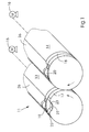
- FIG. 1 and 2 comprises a Printing machine 11, a first cylinder 13 and a second cylinder 14.
- Each cylinder 13, 14 is a sheet 12 of substrate transporting cylinder, such as. B. a Impression cylinder or a transfer drum.
- the first cylinder 13 is from a first motor 15 rotatably driven and the second cylinder 14 of a second Engine 16.
- first locking cam 17 and a first cam follower 19 attached to the second cylinder 14 and a second locking curve 18 and a second cam follower 20.
- the cam followers 19, 20 are rollers.
- Each safety curve 17, 18 has a trough 21 with a leading edge in the direction of rotation 22 and a Trailing edge 23.
- Each cylinder 13, 14 has a cylinder channel 26 with a therein arranged gripper system 27th
- the respective gripper system 27 comprises a gripper 4 and a gripper pad 5, between which the sheet 12 is clamped when gripping.
- the gripper 4 When gripping the bow 12, the gripper 4 is pivoted by means of a gripper shaft 11 to the gripper pad 5.
- This closing of the gripper system 27 and the opening are by means of a Controlled cam gear, which includes a roller lever 2 and a control cam 7.
- a roller lever 2 Of the Roller lever 2 is rotatably connected to the gripper shaft 1 and carries a cam roller 3, which is held by a roller lever spring 24 on the control cam 7.
- the clamping force of the gripper 4 is determined by a gripper spring 9, the one Compression spring is and between a mounted on the gripper shaft 1 and the gripper 4 firmly connected gripper housing 28 and a stop is biased.
- the stop is firmly connected to the gripper shaft 1.
- the gripper pad 5 is in a substantially radial direction 29 inwards slidably mounted in the cylinder 13 and 14 and by a gripper support spring 8 in Opposite direction charged.
- the gripper support spring 8 is stronger, d. H. a larger spring force generating, as the gripper spring 9.
- a pin-shaped driver 6 arranged, which is contacted by the roller lever 2.
- the control cam 7 is connected via a rotary joint 30 with a machine frame 31 and at its the hinge 30 opposite end by a curve support 10th supported.
- the curve support 10 is also pivotally connected to the machine frame 31st connected and represented by a shift lever 32 from a full line Support position adjustable in a release position shown with phantom line.
- Shift lever 32 carries at one end of the cam follower 19 and 20 and contacted with its other end when switching the curve support 10.
- the shift lever 32 is pivotally mounted in the cylinder 13 and 14 and by a return spring 25th loaded.
- a disturbance of the synchronous operation can, for. B. in case of failure of one of the motors 15, 16 occur and involves the risk of a collision of the gripper system 27 of the first cylinder 13 with the second cylinder 14 in itself, because the two cylinders 13, 14 does not have a Synchronous form-locking locking gear pair are rotatably coupled together. This risk of collision is exceeded when a certain rotation angle difference between the cylinders 13, 14 acute.
- the shift lever 32 consequently beats with its first cam follower 19 opposite lever arm on the curve support 10 and pushes it out of their Supporting position out, so that the cam support 10, the cam 7 releases and the latter 2 can be folded down with respect to FIG.
- the roller lever spring 24 presses over the roller lever 2 and thereby the roller lever. 2 contacted driver 6, the gripper pad 5 against the action of the gripper pad spring 8 inside the cylinder.
- the gripper system 27 remains after activation the sinking mechanism over several revolutions of the first cylinder 18 and to the Deactivation of the retracting mechanism permanently retracted.
- the curve support 10, z. B. by means an actuator, founded back to its support position, whereby the control cam. 7 is folded up and thereby by the control cam 7 of the roller lever 2 against the Effect of the roller lever spring 24 is pivoted back, so that the gripper support spring 8 the gripper pad 5 against the direction 29 cantechnischverstellen.
- the gripper system 27 of the second cylinder 14 is formed and operates this Retraction mechanism.
- the sunken mechanism of the second cylinder 14 pulls it Gripper system 27 in response to a between the second cylinder 14 and a (not shown in the drawing) third cylinder occurring rotational angle difference or Synchronous running fault in the cylinder interior.
- the second curve follower 20 acts with one (also not shown in the drawing) third locking curve of the third Cylinder together.
- FIG. 3 differs from that in FIG. 2 shown only by the use of a slide switch 33 or tappet in Active connection with a wedge surface 34 for actuating the curve support 10 comes.
Abstract
Description
- Figur 1
- ein Druckmaschinen-Zylinderpaar,
- Figur 2
- einen Greifersystem-Versenkmechanismus, mit dem jeder Zylinder des Paares aus Figur 1 ausgestattet ist, und
- Figur 3
- eine Modifikation des in Figur 2 dargestellten Versenkmechanismus.
- 1
- Greiferwelle
- 2
- Rollenhebel
- 3
- Kurvenrolle
- 4
- Greifer
- 5
- Greiferauflage
- 6
- Mitnehmer
- 7
- Steuerkurve
- 8
- Greiferauflage-Feder
- 9
- Greifer-Feder
- 10
- Kurvenstütze
- 11
- Druckmaschine
- 12
- Bogen
- 13
- erster Zylinder
- 14
- zweiter Zylinder
- 15
- erster Motor
- 16
- zweiter Motor
- 17
- erste Sicherungskurve
- 18
- zweite Sicherungskurve
- 19
- erster Kurvenfolger
- 20
- zweiter Kurvenfolger
- 21
- Mulde
- 22
- vorlaufende Flanke
- 23
- nachlaufende Flanke
- 24
- Rollenhebel-Feder
- 25
- Rückstell-Feder
- 26
- Zylinderkanal
- 27
- Greifersystem
- 28
- Greifergehäuse
- 29
- Richtung
- 30
- Drehgelenk
- 31
- Maschinengestell
- 32
- Schalthebel
- 33
- Schaltschieber
- 34
- Keilfläche
- 35
- Versenkmechanismus
Claims (8)
- Verfahren zum sicheren Betrieb einer Druckmaschine (11), wobei ein erster Zylinder (13) durch einen ersten Motor (15) und ein zweiter Zylinder (14) durch einen zweiten Motor (16) angetrieben werden und der erste Zylinder (13) mittels eines Greifersystems (27) Bogen (12) vom zweiten Zylinder (14) übernimmt oder an letzteren übergibt,
dadurch gekennzeichnet, dass das Greifersystem (27) bei einer zwischen den Zylindern (13, 14) auftretenden Synchronlaufabweichung zumindest teilweise und so weit in den ersten Zylinder (13) eingezogen wird, dass eine Kollision des Greifersystems (27) mit dem zweiten Zylinder (14) verhindert wird. - Druckmaschine (11) zur Durchführung des Verfahrens nach Anspruch 1, umfassend einen ersten Zylinder (13) mit einem Greifersystem (27), einen ersten Motor (15) zum Antreiben des ersten Zylinders (13), einen zweiten Zylinder (14) und einen zweiten Motor (16) zum Antreiben des zweiten Zylinders (14),
dadurch gekennzeichnet, dass der erste Zylinder (13) einen Versenkmechanismus (35) zum bei einer zwischen den Zylindern (13, 14) auftretenden Synchronlaufabweichung zwangsweise erfolgenden Einziehen des Greifersystems (27) in den ersten Zylinder (13) aufweist. - Druckmaschine nach Anspruch 2,
dadurch gekennzeichnet, dass der Versenkmechanismus (35) eine sich mit dem ersten Zylinder (13) mitdrehende, erste Schalteinrichtung umfasst und dem zweiten Zylinder (14) eine sich mit letzterem mitdrehende, zweite Schalteinrichtung derart zugeordnet ist, dass die Schalteinrichtungen beim Auftreten der Synchronlaufabweichung in Schaltkontakt miteinander gelangen. - Druckmaschine nach Anspruch 3,
dadurch gekennzeichnet, dass die zweite Schalteinrichtung eine erste Flanke (22) und eine zweite Flanke (23) aufweist, die in Drehrichtung einander gegenüberliegend und mit Spiel zur beim störungsfreien Synchronlauf kontaktlos in die zweite Schalteinrichtung eingreifenden, ersten Schalteinrichtung angeordnet sind. - Druckmaschine nach Anspruch 4,
dadurch gekennzeichnet, dass die erste Schalteinrichtung ein Schalthebel (32) ist, der derart angeordnet ist, dass der Schalthebel (32) infolge eines Schaltkontakts zwischen dem Schalthebel (32) und der ersten Flanke (22) in dieselbe Drehrichtung wie infolge eines Schaltkontakts zwischen dem Schalthebel und der zweiten Flanke (23) schwenkbar ist. - Druckmaschine nach einem der Ansprüche 3 bis 5,
dadurch gekennzeichnet, dass die zweite Schalteinrichtung eine Sicherungskurve (18) ist. - Druckmaschine nach einem der Ansprüche 3 bis 6,
dadurch gekennzeichnet, dass die erste Schalteinrichtung zum Betätigen einer das Greifersystem (27) steuernden Steuerkurve (7) angeordnet ist. - Druckmaschine nach Anspruch 7,
dadurch gekennzeichnet, dass die Steuerkurve (7) beim störungsfreien Synchronlauf durch eine Kurvenstütze (10) abgestützt ist, welche derart angeordnet ist, dass beim Auftreten der Synchronlaufabweichung die erste Schalteinrichtung infolge ihres Schaltkontaktes mit der zweiten Schalteinrichtung an die Kurvenstütze (10) anschlägt und diese dadurch so verstellt, dass die Kurvenstütze (10) eine Verstellung der Steuerkurve (7) freigibt.
Applications Claiming Priority (2)
| Application Number | Priority Date | Filing Date | Title |
|---|---|---|---|
| DE102004030142A DE102004030142A1 (de) | 2004-06-22 | 2004-06-22 | Verfahren zum sicheren Betrieb einer Druckmaschine und Druckmaschine zur Durchführung des Verfahrens |
| DE102004030142 | 2004-06-22 |
Publications (2)
| Publication Number | Publication Date |
|---|---|
| EP1609598A1 true EP1609598A1 (de) | 2005-12-28 |
| EP1609598B1 EP1609598B1 (de) | 2012-04-18 |
Family
ID=34981352
Family Applications (1)
| Application Number | Title | Priority Date | Filing Date |
|---|---|---|---|
| EP05105056A Not-in-force EP1609598B1 (de) | 2004-06-22 | 2005-06-09 | Verfahren zum sicheren Betrieb einer Druckmaschine und Druckmaschine zur Durchführung des Verfahrens |
Country Status (5)
| Country | Link |
|---|---|
| EP (1) | EP1609598B1 (de) |
| JP (1) | JP4762615B2 (de) |
| CN (1) | CN100509393C (de) |
| AT (1) | ATE553924T1 (de) |
| DE (1) | DE102004030142A1 (de) |
Cited By (1)
| Publication number | Priority date | Publication date | Assignee | Title |
|---|---|---|---|---|
| EP3254852A1 (de) | 2016-06-07 | 2017-12-13 | Heidelberger Druckmaschinen AG | Druckmaschine mit mittels elektromotor einzeln angetriebenen zylindern |
Families Citing this family (1)
| Publication number | Priority date | Publication date | Assignee | Title |
|---|---|---|---|---|
| DE202004018313U1 (de) * | 2004-11-26 | 2005-01-20 | Man Roland Druckmaschinen Ag | Greifersystem für einen Druckzylinder einer Bogendruckmaschine |
Citations (4)
| Publication number | Priority date | Publication date | Assignee | Title |
|---|---|---|---|---|
| US4475459A (en) * | 1980-12-24 | 1984-10-09 | M.A.N.-Roland Druckmaschinen Aktiengesellschaft | Impression cylinder for sheet-fed rotogravure presses |
| DE4202722A1 (de) | 1992-01-31 | 1993-08-05 | Heidelberger Druckmasch Ag | Sicherheitseinrichtung fuer regelungen oder steuerungen von antriebseinheiten einer druckmaschine |
| DE19909686A1 (de) | 1999-03-05 | 2000-09-07 | Koenig & Bauer Ag | Einrichtung zur Steuerung der Greifer eines Druckzylinders einer Rotationsdruckmaschine |
| US20020112627A1 (en) * | 2001-02-20 | 2002-08-22 | Stefan Mutschall | Device having a cylinder including a gripper system |
Family Cites Families (6)
| Publication number | Priority date | Publication date | Assignee | Title |
|---|---|---|---|---|
| GB434422A (en) * | 1934-02-27 | 1935-08-27 | Ernest William Haward | Improvements relating to printing presses |
| SE7614362L (sv) * | 1976-12-21 | 1978-06-22 | Solna Offset Ab | Arkvendare |
| DE19752680A1 (de) * | 1997-11-28 | 1999-06-02 | Heidelberger Druckmasch Ag | Verfahren und Vorrichtung zur Übergabe der Hinterkante eines Bogens in einer Wendeeinrichtung einer Bogenrotationsdruckmaschine |
| JP3466905B2 (ja) * | 1998-01-27 | 2003-11-17 | 大日本スクリーン製造株式会社 | 印刷機の咥え装置 |
| DE10102080B4 (de) * | 2001-01-18 | 2014-03-06 | Heidelberger Druckmaschinen Ag | Einrichtung zur Wendung flächiger Exemplare in einer bogenverarbeitenden Rotationsdruckmaschine |
| DE20102712U1 (de) * | 2001-02-16 | 2001-04-05 | Roland Man Druckmasch | Bogenführungseinrichtung in einer Druckmaschine |
-
2004
- 2004-06-22 DE DE102004030142A patent/DE102004030142A1/de not_active Withdrawn
-
2005
- 2005-06-09 AT AT05105056T patent/ATE553924T1/de active
- 2005-06-09 EP EP05105056A patent/EP1609598B1/de not_active Not-in-force
- 2005-06-22 CN CNB2005101098027A patent/CN100509393C/zh not_active Expired - Fee Related
- 2005-06-22 JP JP2005181720A patent/JP4762615B2/ja not_active Expired - Fee Related
Patent Citations (4)
| Publication number | Priority date | Publication date | Assignee | Title |
|---|---|---|---|---|
| US4475459A (en) * | 1980-12-24 | 1984-10-09 | M.A.N.-Roland Druckmaschinen Aktiengesellschaft | Impression cylinder for sheet-fed rotogravure presses |
| DE4202722A1 (de) | 1992-01-31 | 1993-08-05 | Heidelberger Druckmasch Ag | Sicherheitseinrichtung fuer regelungen oder steuerungen von antriebseinheiten einer druckmaschine |
| DE19909686A1 (de) | 1999-03-05 | 2000-09-07 | Koenig & Bauer Ag | Einrichtung zur Steuerung der Greifer eines Druckzylinders einer Rotationsdruckmaschine |
| US20020112627A1 (en) * | 2001-02-20 | 2002-08-22 | Stefan Mutschall | Device having a cylinder including a gripper system |
Cited By (1)
| Publication number | Priority date | Publication date | Assignee | Title |
|---|---|---|---|---|
| EP3254852A1 (de) | 2016-06-07 | 2017-12-13 | Heidelberger Druckmaschinen AG | Druckmaschine mit mittels elektromotor einzeln angetriebenen zylindern |
Also Published As
| Publication number | Publication date |
|---|---|
| ATE553924T1 (de) | 2012-05-15 |
| DE102004030142A1 (de) | 2006-01-19 |
| EP1609598B1 (de) | 2012-04-18 |
| CN1749004A (zh) | 2006-03-22 |
| CN100509393C (zh) | 2009-07-08 |
| JP4762615B2 (ja) | 2011-08-31 |
| JP2006007773A (ja) | 2006-01-12 |
Similar Documents
| Publication | Publication Date | Title |
|---|---|---|
| DE3940796C2 (de) | ||
| DE3110468C2 (de) | ||
| DE1107246B (de) | Bogenrotationsdruckmaschine | |
| DE2557866A1 (de) | Rotierende vorgreifertrommel | |
| DE1786371A1 (de) | Druckverfahren und Druckmaschine fuer Mehrfarben-Schoen- und Widerdruck | |
| EP0736384B1 (de) | Vorrichtung zur Druckan- und -abstellung und Verfahren zum Steuern dieser Vorrichtung | |
| DE3008226A1 (de) | Bogenrotationsdruckmaschine mit einem von unten arbeitenden vorgreifer | |
| EP1819515B1 (de) | Greifersystem für einen bogen führenden zylinder einer bogendruckmaschine | |
| DE102015209696B4 (de) | Greifersystem und Verfahren zur Herstellung eines Greifersystems | |
| DE3535694A1 (de) | Bogenoffsetrotationsdruckmaschine in reihenbauweise | |
| EP0668161B1 (de) | Vorrichtung zur Uebergabe einzelner Bögen an den Druckzylinder einer Bogenrotationsdruckmaschine | |
| EP1104858B1 (de) | Vorrichtung zur Sicherung eines korrekten Zahneingriffes beim Koppeln zweier Zahnräder | |
| EP1609598B1 (de) | Verfahren zum sicheren Betrieb einer Druckmaschine und Druckmaschine zur Durchführung des Verfahrens | |
| DE4424977A1 (de) | Bogenabweiser an bogenführenden Zylindern | |
| DE10057571B4 (de) | Verfahren zur Zylinderverstellung und Druckmaschinen zur Durchführung des Verfahrens | |
| DE102007009884C5 (de) | Druckmaschine | |
| DE19901699A1 (de) | Verfahren und eine Vorrichtung zur Durchführung des Verfahrens zur Beseitigung von rhythmischen Passerfehlern in Rotationsdruckmaschinen | |
| DE10304495A1 (de) | Verfahren und Anordnung für die Synchronisierung eines elektrischen Einzelantriebes | |
| DD157047A3 (de) | Bogenleiteinrichtung in bogenfuehrungszylindern | |
| DE4332491C2 (de) | Saugluftsteuerung für Saugersystemen in Wendetrommeln von Druckmaschinen | |
| DE4324746C2 (de) | Einrichtung zum Umstellen eines Sauger- und Greifersystems | |
| DE102006025789A1 (de) | Bogendruckmaschine | |
| DE19909686B4 (de) | Einrichtung zur Steuerung der Greifer eines Druckzylinders einer Rotationsdruckmaschine | |
| DE102008004811B4 (de) | Vorrichtung zum Fördern eines Bogens zwischen zwei Druckwerken einer Druckmaschine in Reihenbauweise | |
| DE1913844C3 (de) | Antriebsvorrichtung einer rotie renden Vorgreifertrommel mit Vorgreifern zur Anlage von Bogen an einem Zylinder |
Legal Events
| Date | Code | Title | Description |
|---|---|---|---|
| PUAI | Public reference made under article 153(3) epc to a published international application that has entered the european phase |
Free format text: ORIGINAL CODE: 0009012 |
|
| AK | Designated contracting states |
Kind code of ref document: A1 Designated state(s): AT BE BG CH CY CZ DE DK EE ES FI FR GB GR HU IE IS IT LI LT LU MC NL PL PT RO SE SI SK TR |
|
| AX | Request for extension of the european patent |
Extension state: AL BA HR LV MK YU |
|
| 17P | Request for examination filed |
Effective date: 20060628 |
|
| AKX | Designation fees paid |
Designated state(s): AT BE BG CH CY CZ DE DK EE ES FI FR GB GR HU IE IS IT LI LT LU MC NL PL PT RO SE SI SK TR |
|
| GRAP | Despatch of communication of intention to grant a patent |
Free format text: ORIGINAL CODE: EPIDOSNIGR1 |
|
| GRAS | Grant fee paid |
Free format text: ORIGINAL CODE: EPIDOSNIGR3 |
|
| GRAA | (expected) grant |
Free format text: ORIGINAL CODE: 0009210 |
|
| AK | Designated contracting states |
Kind code of ref document: B1 Designated state(s): AT BE BG CH CY CZ DE DK EE ES FI FR GB GR HU IE IS IT LI LT LU MC NL PL PT RO SE SI SK TR |
|
| REG | Reference to a national code |
Ref country code: GB Ref legal event code: FG4D Free format text: NOT ENGLISH |
|
| REG | Reference to a national code |
Ref country code: DE Ref legal event code: R081 Ref document number: 502005012640 Country of ref document: DE Owner name: HEIDELBERGER DRUCKMASCHINEN AG, DE Free format text: FORMER OWNER: HEIDELBERGER DRUCKMASCHINEN AG, 69115 HEIDELBERG, DE |
|
| REG | Reference to a national code |
Ref country code: CH Ref legal event code: EP |
|
| REG | Reference to a national code |
Ref country code: IE Ref legal event code: FG4D Free format text: LANGUAGE OF EP DOCUMENT: GERMAN |
|
| REG | Reference to a national code |
Ref country code: AT Ref legal event code: REF Ref document number: 553924 Country of ref document: AT Kind code of ref document: T Effective date: 20120515 |
|
| REG | Reference to a national code |
Ref country code: NL Ref legal event code: T3 |
|
| REG | Reference to a national code |
Ref country code: DE Ref legal event code: R096 Ref document number: 502005012640 Country of ref document: DE Effective date: 20120614 |
|
| LTIE | Lt: invalidation of european patent or patent extension |
Effective date: 20120418 |
|
| PG25 | Lapsed in a contracting state [announced via postgrant information from national office to epo] |
Ref country code: IS Free format text: LAPSE BECAUSE OF FAILURE TO SUBMIT A TRANSLATION OF THE DESCRIPTION OR TO PAY THE FEE WITHIN THE PRESCRIBED TIME-LIMIT Effective date: 20120818 Ref country code: CY Free format text: LAPSE BECAUSE OF FAILURE TO SUBMIT A TRANSLATION OF THE DESCRIPTION OR TO PAY THE FEE WITHIN THE PRESCRIBED TIME-LIMIT Effective date: 20120418 Ref country code: FI Free format text: LAPSE BECAUSE OF FAILURE TO SUBMIT A TRANSLATION OF THE DESCRIPTION OR TO PAY THE FEE WITHIN THE PRESCRIBED TIME-LIMIT Effective date: 20120418 Ref country code: LT Free format text: LAPSE BECAUSE OF FAILURE TO SUBMIT A TRANSLATION OF THE DESCRIPTION OR TO PAY THE FEE WITHIN THE PRESCRIBED TIME-LIMIT Effective date: 20120418 Ref country code: SE Free format text: LAPSE BECAUSE OF FAILURE TO SUBMIT A TRANSLATION OF THE DESCRIPTION OR TO PAY THE FEE WITHIN THE PRESCRIBED TIME-LIMIT Effective date: 20120418 Ref country code: PL Free format text: LAPSE BECAUSE OF FAILURE TO SUBMIT A TRANSLATION OF THE DESCRIPTION OR TO PAY THE FEE WITHIN THE PRESCRIBED TIME-LIMIT Effective date: 20120418 |
|
| PG25 | Lapsed in a contracting state [announced via postgrant information from national office to epo] |
Ref country code: GR Free format text: LAPSE BECAUSE OF FAILURE TO SUBMIT A TRANSLATION OF THE DESCRIPTION OR TO PAY THE FEE WITHIN THE PRESCRIBED TIME-LIMIT Effective date: 20120719 Ref country code: PT Free format text: LAPSE BECAUSE OF FAILURE TO SUBMIT A TRANSLATION OF THE DESCRIPTION OR TO PAY THE FEE WITHIN THE PRESCRIBED TIME-LIMIT Effective date: 20120820 Ref country code: SI Free format text: LAPSE BECAUSE OF FAILURE TO SUBMIT A TRANSLATION OF THE DESCRIPTION OR TO PAY THE FEE WITHIN THE PRESCRIBED TIME-LIMIT Effective date: 20120418 |
|
| BERE | Be: lapsed |
Owner name: HEIDELBERGER DRUCKMASCHINEN A.G. Effective date: 20120630 |
|
| PG25 | Lapsed in a contracting state [announced via postgrant information from national office to epo] |
Ref country code: SK Free format text: LAPSE BECAUSE OF FAILURE TO SUBMIT A TRANSLATION OF THE DESCRIPTION OR TO PAY THE FEE WITHIN THE PRESCRIBED TIME-LIMIT Effective date: 20120418 Ref country code: RO Free format text: LAPSE BECAUSE OF FAILURE TO SUBMIT A TRANSLATION OF THE DESCRIPTION OR TO PAY THE FEE WITHIN THE PRESCRIBED TIME-LIMIT Effective date: 20120418 Ref country code: EE Free format text: LAPSE BECAUSE OF FAILURE TO SUBMIT A TRANSLATION OF THE DESCRIPTION OR TO PAY THE FEE WITHIN THE PRESCRIBED TIME-LIMIT Effective date: 20120418 Ref country code: MC Free format text: LAPSE BECAUSE OF NON-PAYMENT OF DUE FEES Effective date: 20120630 Ref country code: DK Free format text: LAPSE BECAUSE OF FAILURE TO SUBMIT A TRANSLATION OF THE DESCRIPTION OR TO PAY THE FEE WITHIN THE PRESCRIBED TIME-LIMIT Effective date: 20120418 Ref country code: CZ Free format text: LAPSE BECAUSE OF FAILURE TO SUBMIT A TRANSLATION OF THE DESCRIPTION OR TO PAY THE FEE WITHIN THE PRESCRIBED TIME-LIMIT Effective date: 20120418 |
|
| PLBE | No opposition filed within time limit |
Free format text: ORIGINAL CODE: 0009261 |
|
| STAA | Information on the status of an ep patent application or granted ep patent |
Free format text: STATUS: NO OPPOSITION FILED WITHIN TIME LIMIT |
|
| PG25 | Lapsed in a contracting state [announced via postgrant information from national office to epo] |
Ref country code: IT Free format text: LAPSE BECAUSE OF FAILURE TO SUBMIT A TRANSLATION OF THE DESCRIPTION OR TO PAY THE FEE WITHIN THE PRESCRIBED TIME-LIMIT Effective date: 20120418 |
|
| 26N | No opposition filed |
Effective date: 20130121 |
|
| GBPC | Gb: european patent ceased through non-payment of renewal fee |
Effective date: 20120718 |
|
| REG | Reference to a national code |
Ref country code: IE Ref legal event code: MM4A |
|
| PG25 | Lapsed in a contracting state [announced via postgrant information from national office to epo] |
Ref country code: IE Free format text: LAPSE BECAUSE OF NON-PAYMENT OF DUE FEES Effective date: 20120609 Ref country code: GB Free format text: LAPSE BECAUSE OF NON-PAYMENT OF DUE FEES Effective date: 20120718 Ref country code: BE Free format text: LAPSE BECAUSE OF NON-PAYMENT OF DUE FEES Effective date: 20120630 Ref country code: ES Free format text: LAPSE BECAUSE OF FAILURE TO SUBMIT A TRANSLATION OF THE DESCRIPTION OR TO PAY THE FEE WITHIN THE PRESCRIBED TIME-LIMIT Effective date: 20120729 |
|
| REG | Reference to a national code |
Ref country code: DE Ref legal event code: R097 Ref document number: 502005012640 Country of ref document: DE Effective date: 20130121 |
|
| PG25 | Lapsed in a contracting state [announced via postgrant information from national office to epo] |
Ref country code: BG Free format text: LAPSE BECAUSE OF FAILURE TO SUBMIT A TRANSLATION OF THE DESCRIPTION OR TO PAY THE FEE WITHIN THE PRESCRIBED TIME-LIMIT Effective date: 20120718 |
|
| REG | Reference to a national code |
Ref country code: AT Ref legal event code: MM01 Ref document number: 553924 Country of ref document: AT Kind code of ref document: T Effective date: 20120609 |
|
| PG25 | Lapsed in a contracting state [announced via postgrant information from national office to epo] |
Ref country code: AT Free format text: LAPSE BECAUSE OF NON-PAYMENT OF DUE FEES Effective date: 20120609 |
|
| PG25 | Lapsed in a contracting state [announced via postgrant information from national office to epo] |
Ref country code: TR Free format text: LAPSE BECAUSE OF FAILURE TO SUBMIT A TRANSLATION OF THE DESCRIPTION OR TO PAY THE FEE WITHIN THE PRESCRIBED TIME-LIMIT Effective date: 20120418 |
|
| PG25 | Lapsed in a contracting state [announced via postgrant information from national office to epo] |
Ref country code: LU Free format text: LAPSE BECAUSE OF NON-PAYMENT OF DUE FEES Effective date: 20120609 |
|
| PG25 | Lapsed in a contracting state [announced via postgrant information from national office to epo] |
Ref country code: HU Free format text: LAPSE BECAUSE OF FAILURE TO SUBMIT A TRANSLATION OF THE DESCRIPTION OR TO PAY THE FEE WITHIN THE PRESCRIBED TIME-LIMIT Effective date: 20050609 |
|
| REG | Reference to a national code |
Ref country code: FR Ref legal event code: PLFP Year of fee payment: 11 |
|
| PGFP | Annual fee paid to national office [announced via postgrant information from national office to epo] |
Ref country code: CH Payment date: 20150621 Year of fee payment: 11 |
|
| PGFP | Annual fee paid to national office [announced via postgrant information from national office to epo] |
Ref country code: NL Payment date: 20150621 Year of fee payment: 11 Ref country code: FR Payment date: 20150622 Year of fee payment: 11 |
|
| REG | Reference to a national code |
Ref country code: DE Ref legal event code: R081 Ref document number: 502005012640 Country of ref document: DE Owner name: HEIDELBERGER DRUCKMASCHINEN AG, DE Free format text: FORMER OWNER: HEIDELBERGER DRUCKMASCHINEN AKTIENGESELLSCHAFT, 69115 HEIDELBERG, DE |
|
| REG | Reference to a national code |
Ref country code: CH Ref legal event code: PL |
|
| REG | Reference to a national code |
Ref country code: NL Ref legal event code: MM Effective date: 20160701 |
|
| REG | Reference to a national code |
Ref country code: FR Ref legal event code: ST Effective date: 20170228 |
|
| PG25 | Lapsed in a contracting state [announced via postgrant information from national office to epo] |
Ref country code: FR Free format text: LAPSE BECAUSE OF NON-PAYMENT OF DUE FEES Effective date: 20160630 Ref country code: CH Free format text: LAPSE BECAUSE OF NON-PAYMENT OF DUE FEES Effective date: 20160630 Ref country code: LI Free format text: LAPSE BECAUSE OF NON-PAYMENT OF DUE FEES Effective date: 20160630 |
|
| PG25 | Lapsed in a contracting state [announced via postgrant information from national office to epo] |
Ref country code: NL Free format text: LAPSE BECAUSE OF NON-PAYMENT OF DUE FEES Effective date: 20160701 |
|
| PGFP | Annual fee paid to national office [announced via postgrant information from national office to epo] |
Ref country code: DE Payment date: 20180630 Year of fee payment: 14 |
|
| REG | Reference to a national code |
Ref country code: DE Ref legal event code: R119 Ref document number: 502005012640 Country of ref document: DE |
|
| PG25 | Lapsed in a contracting state [announced via postgrant information from national office to epo] |
Ref country code: DE Free format text: LAPSE BECAUSE OF NON-PAYMENT OF DUE FEES Effective date: 20200101 |