EP1609523A1 - Dynamischer Durchfluss-Mischvorrichtung - Google Patents
Dynamischer Durchfluss-Mischvorrichtung Download PDFInfo
- Publication number
- EP1609523A1 EP1609523A1 EP05291169A EP05291169A EP1609523A1 EP 1609523 A1 EP1609523 A1 EP 1609523A1 EP 05291169 A EP05291169 A EP 05291169A EP 05291169 A EP05291169 A EP 05291169A EP 1609523 A1 EP1609523 A1 EP 1609523A1
- Authority
- EP
- European Patent Office
- Prior art keywords
- rotor
- holes
- disks
- discs
- casing
- Prior art date
- Legal status (The legal status is an assumption and is not a legal conclusion. Google has not performed a legal analysis and makes no representation as to the accuracy of the status listed.)
- Granted
Links
Images


Classifications
-
- B—PERFORMING OPERATIONS; TRANSPORTING
- B01—PHYSICAL OR CHEMICAL PROCESSES OR APPARATUS IN GENERAL
- B01F—MIXING, e.g. DISSOLVING, EMULSIFYING OR DISPERSING
- B01F27/00—Mixers with rotary stirring devices in fixed receptacles; Kneaders
- B01F27/60—Mixers with rotary stirring devices in fixed receptacles; Kneaders with stirrers rotating about a horizontal or inclined axis
- B01F27/73—Mixers with rotary stirring devices in fixed receptacles; Kneaders with stirrers rotating about a horizontal or inclined axis with rotary discs
-
- B—PERFORMING OPERATIONS; TRANSPORTING
- B01—PHYSICAL OR CHEMICAL PROCESSES OR APPARATUS IN GENERAL
- B01F—MIXING, e.g. DISSOLVING, EMULSIFYING OR DISPERSING
- B01F23/00—Mixing according to the phases to be mixed, e.g. dispersing or emulsifying
- B01F23/40—Mixing liquids with liquids; Emulsifying
- B01F23/47—Mixing liquids with liquids; Emulsifying involving high-viscosity liquids, e.g. asphalt
-
- B—PERFORMING OPERATIONS; TRANSPORTING
- B01—PHYSICAL OR CHEMICAL PROCESSES OR APPARATUS IN GENERAL
- B01F—MIXING, e.g. DISSOLVING, EMULSIFYING OR DISPERSING
- B01F25/00—Flow mixers; Mixers for falling materials, e.g. solid particles
- B01F25/40—Static mixers
- B01F25/45—Mixers in which the materials to be mixed are pressed together through orifices or interstitial spaces, e.g. between beads
- B01F25/452—Mixers in which the materials to be mixed are pressed together through orifices or interstitial spaces, e.g. between beads characterised by elements provided with orifices or interstitial spaces
- B01F25/4521—Mixers in which the materials to be mixed are pressed together through orifices or interstitial spaces, e.g. between beads characterised by elements provided with orifices or interstitial spaces the components being pressed through orifices in elements, e.g. flat plates or cylinders, which obstruct the whole diameter of the tube
-
- B—PERFORMING OPERATIONS; TRANSPORTING
- B01—PHYSICAL OR CHEMICAL PROCESSES OR APPARATUS IN GENERAL
- B01F—MIXING, e.g. DISSOLVING, EMULSIFYING OR DISPERSING
- B01F27/00—Mixers with rotary stirring devices in fixed receptacles; Kneaders
- B01F27/05—Stirrers
- B01F27/11—Stirrers characterised by the configuration of the stirrers
- B01F27/19—Stirrers with two or more mixing elements mounted in sequence on the same axis
- B01F27/191—Stirrers with two or more mixing elements mounted in sequence on the same axis with similar elements
-
- B—PERFORMING OPERATIONS; TRANSPORTING
- B01—PHYSICAL OR CHEMICAL PROCESSES OR APPARATUS IN GENERAL
- B01F—MIXING, e.g. DISSOLVING, EMULSIFYING OR DISPERSING
- B01F35/00—Accessories for mixers; Auxiliary operations or auxiliary devices; Parts or details of general application
- B01F35/50—Mixing receptacles
- B01F35/53—Mixing receptacles characterised by the configuration of the interior, e.g. baffles for facilitating the mixing of components
- B01F35/531—Mixing receptacles characterised by the configuration of the interior, e.g. baffles for facilitating the mixing of components with baffles, plates or bars on the wall or the bottom
Definitions
- helical screw rotors have the disadvantage of being expensive manufacturing and this fact are reserved for applications in which the other types of rotors may not be suitable.
- the vane rotors On their side, the vane rotors have the disadvantage of offering too much passage section (angular sectors between successive palettes peripherally).
- pallets which are often fixed by welding on the central shaft of the rotor, can prove fragile especially in the case of products with very large viscosity.
- the object of the invention is to overcome the disadvantages currently known devices and to propose an improved device that responds better, especially as to its efficiency and cost, the requirements of the practical in some applications.
- the invention proposes an in-line dynamic mixing device as explained in the preamble which, being arranged according to the invention, is characterized in that the rotor supports a multiplicity of successive coaxial disks, each disk having a plurality of holes, and the casing supports a multiplicity of successive coaxial disks, each disk having a central orifice for the passage of the rotor and a plurality of holes, the rotor disks and the housing disks being mutually axially alternated and spaced from each other by successive intervals.
- the discs fixed or rotary, are substantially perpendicular to the axis of rotation of the rotor and bear almost no axial effort.
- the device thus constituted is therefore very robust in same time as it is of economic manufacture, the perforated discs which can be mass produced by conventional machining means.
- the drive of the rotor can be provided by means of motorization, especially motor electric, commonly available and therefore of a lesser cost.
- a mixing device presents a very large number of structural parameters and the adjustment of one or more of them allows a adaptation to mixing conditions and / or very diverse products.
- holes are distributed circularly in the vicinity of the periphery of at least some rotor disks and / or less some crankcase disks. But he is also possible to have holes arranged, particularly circumscribed, outside the periphery of at least some rotor disks and / or less some crankcase disks.
- holes at least some rotor discs and / or holes at least some casing disks are round to treat products of small granulometry or liquid or non-round shape (particularly angular such as triangular) to process more products large granulometry or lumpy.
- holes of different shapes may, where necessary, be provided on the same disc.
- holes of less some adjacent disks respectively of the rotor and housing are centered on circumferences respective substantially identical, ie move substantially opposite each other; or well be centered on respective circumferences significantly different if we wish to better disrupt the flow of the veins of the product to be mixed.
- the holes of at least some adjacent discs respectively of the rotor and the carter are in identical numbers, especially on at least one axial section, or even the whole of the length, or on the contrary that they are in numbers different, especially on at least one axial section, over the entire length.
- these two provisions can be combined on sections successive.
- the intervals between the successive disks belonging alternately the rotor and the casing are equal on at least one section axial. But, if it proves useful for example to hold account for possible variations in viscosity of the product treated between entry and exit as the product is homogenized, it can be envisaged that the intervals between successive disks belonging alternatively to rotor and crankcase differ axially, for example this variation can intervene by successive axial sections; in particular one can foresee that these intervals vary gradually over at least an axial section; In particular, it is possible to envisage that the intervals are smaller in the vicinity of the outlet that near the inlet if the viscosity of the mixed product decreases or is larger if the viscosity of the mixed product increases.
- the rotational speed of the rotor constitutes of course an important parameter of adjustment of operating conditions of the device for obtaining a desired result.
- the housing has a single inlet, in particular disposed coaxially at one of its ends, for the admission of a flow formed by the meeting of at least two primary products, which means that the meeting of primary products was carried out before the device of the invention, for example using a first T-mix (coarse mix) located upstream from the entrance.
- a first T-mix coarse mix
- crankcase can be provided has at least two entries for the admission of respective primary products to be blended, thereby save the first mixer located upstream, the inputs can all be located parallel to the axis at one end of the housing, or at least some entrances can be arranged laterally for example to achieve staged blends of several products.
- each provision can be implemented on the the whole length of the rotor, or only on one axial section of the rotor, successive axial sections can be equipped differently.
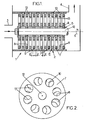
- a dynamic mixer device in line according to the invention intended to intimately mix two or more products primary, has a substantially elongate housing 2 and internally cylindrical of revolution with at least one input 3 (here arranged axially at one end of the housing) for said product to be mixed and at least one output 4 (here arranged laterally) to evacuate the product intimately mixed.
- the device 1 also comprises a rotor 5 extending internally to said housing 2 and coaxially to it, and means for driving in rotation (no shown in Figure 1) are intended to lead to rotation (arrow 6) the rotor 5.
- the rotor 5 supports a multiplicity of disks 7 successive coaxials, each disk 7 having a plurality of through holes 8, a remaining game 9 between the outer edge of each disk 7 and the wall of the casing 2.
- the casing 2 internally supports a multiplicity of successive coaxial disks 10, each disc 10 having a central orifice 11 for the passage of the shaft 12 of the rotor 5 and a plurality of holes 13 through, a game remaining between the inner edge of each disk 10 and the shaft 12 of the rotor.
- the discs 7 of the rotor 5 and the discs 10 of the casing 2 are mutually axially alternated and spaced from each other by respective intervals d .
- the discs can be held apart by spacers and the stacks are held tight by suitable clamping means (clamping rods not shown for the housing discs and axial screw and shoulder for the rotor shaft).
- the device according to the invention as it just exposed can give rise to a very big number of alternative embodiments because of the numerous parameters that can be adapted in the structure.
- the holes are not arranged circularly, or even are arranged randomly.
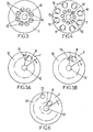
- the holes 8, 13 illustrated in Figures 1 to 5 are round in shape, but it is perfectly conceivable that they have shapes other.
- holes may be provided polygonal, in particular triangular.
- Figure 5A is illustrated by way of example a fixed disk 10 provided with triangular holes 13 (only one being drawn) pointed directed towards the center and a rotating disc 7 (only one fragment of it is drawn) provided with round holes 8.
- Figure 5B is illustrated as another example a fixed disc 10 provided with triangular holes 13 pointed directed outward and a rotating disc 7 (only one fragment of it being drawn) provided with holes 8 round.
- the round and triangular holes being dimensioned mutually so that, in alignment situation, each round hole is entered in the triangular hole opposite.
- the holes 8 of the rotor disks 7 and the holes 13 discs 10 of the casing 2 are located on substantially identical circumferences, so that they are sequentially put into coincidence in some relative angular positions of the rotor disks and the casing.
- such an arrangement is not mandatory and it can be envisaged that the holes of the disks rotor and the holes in the crankcase discs located on different circumferences so that they never be in coincidence as shown in the figure 6 (only a rotating disk fragment 7 being shown) or that they are sequentially only in coincidence partial.
- Another important parameter of the operation of the device lies in the intervals between successive disks 7, 10.
- all the successive disks 7, 10 are spaced apart from one another by equal intervals of value d .
- a simple implementation of this arrangement consists, as illustrated in FIG. 7, in arranging the rotor 5 in several successive sections T 1 , T 2 , T 3 (for example two or three sections) in which the intervals have different values.
- the quantity ⁇ could itself be a constant quantity, or a variable quantity depending on the index i , or even a percentage of a basic value or the value of the preceding interval.
- the holes 8, 13 opposite adjacent discs 7, 10 respectively belonging to the rotor 5 and to the casing 2 have substantially identical sections on at least one axial portion of the rotor. ; for example the holes 8, 13 of round shape illustrated in Figures 1 and 2 have substantially the same diameter over the entire length of the rotor.
- this arrangement is not mandatory, and it is possible to envisage holes 8, 13 respectively having different sections on several axial sections as illustrated in FIG. 8 (here this arrangement is associated with identical intervals between the disks). successive), or continuously variable sections on at least one axial section.
- the holes 8, 13 of round shape have different diameters ⁇ 1 , ⁇ 2 , ⁇ 3 , which here decrease on respective axial sections T 1 , T 2 , T 3 of the rotor for a mixture having a decreasing viscosity (these diameters being increasing in the case of a mixture with increasing viscosity).
- the rotational speed of the rotor is an important parameter for setting the conditions operation of the device required for a given application. Adaptation of games between discs and respectively the crankcase and the rotor allows also affect the flow of the product through the device.
- Figure 9 is illustrated by way of example a mixing device according to the invention shown in its set (the same numerical references to the figures 1 and 2 are used to designate the organs identical).
- the mixer is supposed to be analogous to that of Figure 1, with alternating discs 7, 10 which are separated by equal intervals and which are provided with holes 8, 13 round as shown in Figure 2.
- a first mixer for example a T-mixer
- entry 3 which, in the illustrated example, is an entry axial axis located coaxially with the rotor 5.
- the casing 2 is secured to a frame 14 which is itself fixed on a mounting base 15.
- Shaft 12 of rotor 5 is integral in rotation of the output shaft 16 of a gear reducer speed 17 fixed to the frame 14 (or whose frame 14 is part integral of the crankcase), the speed reducer 17 being itself coupled to the output shaft of an engine Electric drive 18.
- a mixer device dynamic online so arranged uses materials commonly available commercially, and can be realized with a relatively reduced cost.
- the housing may have a single input, for example axial as shown in the figure 9, for the simultaneous admission of primary products; but it is also possible to envisage several entrances, including an entrance or several entrances to a end of the crankcase and another or more entrances located laterally on the housing: it becomes then possible to perform a staged mix of several products; for example two products are introduced, together or separately at one end of the housing and are mixed on a first section of the crankcase, then a third product is introduced laterally and is mixed with the previous ones on a second section of the housing, etc.
Applications Claiming Priority (2)
| Application Number | Priority Date | Filing Date | Title |
|---|---|---|---|
| FR0406670A FR2871711B1 (fr) | 2004-06-18 | 2004-06-18 | Dispositif de melange dynamique en ligne |
| FR0406670 | 2004-06-18 |
Publications (2)
| Publication Number | Publication Date |
|---|---|
| EP1609523A1 true EP1609523A1 (de) | 2005-12-28 |
| EP1609523B1 EP1609523B1 (de) | 2006-08-30 |
Family
ID=34942364
Family Applications (1)
| Application Number | Title | Priority Date | Filing Date |
|---|---|---|---|
| EP05291169A Revoked EP1609523B1 (de) | 2004-06-18 | 2005-05-31 | Dynamische Durchfluss-Mischvorrichtung |
Country Status (6)
| Country | Link |
|---|---|
| US (1) | US20050286343A1 (de) |
| EP (1) | EP1609523B1 (de) |
| JP (1) | JP2006000849A (de) |
| CN (1) | CN1714920A (de) |
| DE (1) | DE602005000098T2 (de) |
| FR (1) | FR2871711B1 (de) |
Families Citing this family (20)
| Publication number | Priority date | Publication date | Assignee | Title |
|---|---|---|---|---|
| KR200450992Y1 (ko) * | 2008-06-30 | 2010-11-16 | 김동식 | 유화유 제조장치 |
| KR200458752Y1 (ko) * | 2009-06-24 | 2012-02-24 | 한국에너지기술(주) | 산소수 제조장치 |
| WO2010002164A2 (ko) * | 2008-06-30 | 2010-01-07 | 한국에너지기술 주식회사 | 산소수 제조장치 |
| KR101297518B1 (ko) * | 2009-10-29 | 2013-08-16 | 주식회사 엘지화학 | 교반장치 및 이에 구비되는 교반후크 |
| JP5727273B2 (ja) * | 2011-03-28 | 2015-06-03 | 株式会社Mgグローアップ | 混合撹拌装置 |
| KR101077266B1 (ko) | 2011-05-24 | 2011-11-01 | 장미고무공업사주식회사 | 코팅장갑용 코팅액의 폼 생성장치 |
| JP5832279B2 (ja) | 2011-12-26 | 2015-12-16 | 株式会社ジェイテクト | 分散装置 |
| KR101221850B1 (ko) * | 2012-03-23 | 2013-01-15 | 주식회사 케이엔에스컴퍼니 | 원 패스 타입 분산 및 유화 장치 |
| CN104918693B (zh) * | 2013-12-27 | 2017-10-20 | 新东工业株式会社 | 分散装置、分散处理系统以及分散方法 |
| CN105171944A (zh) * | 2015-08-17 | 2015-12-23 | 贵州省从江县润田复合材料有限公司 | 一种玻璃钢管内衬树脂和催化剂混合器 |
| JP6465004B2 (ja) * | 2015-11-30 | 2019-02-06 | トヨタ自動車株式会社 | 正極合材ペーストの製造方法 |
| KR101624476B1 (ko) | 2016-01-26 | 2016-05-25 | 최동철 | 미세기포가 함유된 코팅액 공급장치 |
| WO2019124992A2 (ko) * | 2017-12-22 | 2019-06-27 | 황창배 | 나노-마이크로 버블 발생 장치 |
| CN108144467A (zh) * | 2018-01-15 | 2018-06-12 | 中国石油大学(华东) | 一种筛板旋转式的乳化装置及其乳化方法 |
| CN107961693A (zh) * | 2018-01-23 | 2018-04-27 | 罗璐 | 一种气水混合装置 |
| CN108393023A (zh) * | 2018-03-22 | 2018-08-14 | 罗璐 | 一种流体混合装置 |
| CN108236878A (zh) * | 2018-03-22 | 2018-07-03 | 罗璐 | 一种气液混合装置 |
| KR102231445B1 (ko) * | 2020-09-22 | 2021-04-12 | 주식회사 가람이엔지 | 수중 녹조 마이크로 분쇄기 |
| CN112518988A (zh) * | 2020-11-27 | 2021-03-19 | 泰山石膏(河南)有限公司 | 一种石膏针式搅拌机 |
| CN218307353U (zh) * | 2022-08-16 | 2023-01-17 | 宏工科技股份有限公司 | 一种制浆机 |
Citations (5)
| Publication number | Priority date | Publication date | Assignee | Title |
|---|---|---|---|---|
| FR2015544A1 (de) * | 1968-08-12 | 1970-04-30 | Masap Ag | |
| JPH03101820A (ja) * | 1989-09-16 | 1991-04-26 | Nippon Paint Co Ltd | 分散装置 |
| JPH0699047A (ja) * | 1992-09-24 | 1994-04-12 | Canon Inc | 密閉型湿式分散装置 |
| JPH09122467A (ja) * | 1995-11-06 | 1997-05-13 | Mitsui Toatsu Chem Inc | 改良された回転体を有する流通型分散装置 |
| US5779986A (en) * | 1994-12-30 | 1998-07-14 | Karl Fischer Industrieanlagen Gmbh | Reactor device for free-flowing and higher-viscosity media |
Family Cites Families (17)
| Publication number | Priority date | Publication date | Assignee | Title |
|---|---|---|---|---|
| US2734728A (en) * | 1956-02-14 | myers | ||
| US2092992A (en) * | 1935-08-19 | 1937-09-14 | Daniel E Thalman | Emulsifying apparatus |
| US2169338A (en) * | 1938-03-18 | 1939-08-15 | Gas Fuel Corp | Emulsifying mill |
| US2469999A (en) * | 1945-05-30 | 1949-05-10 | Dow Chemical Co | Mixing head for extrusion machines |
| US2740696A (en) * | 1951-03-30 | 1956-04-03 | Exxon Research Engineering Co | Polymerization apparatus unit |
| US2730338A (en) * | 1951-09-14 | 1956-01-10 | Pittsburgh Plate Glass Co | Glass refining apparatus |
| US2798698A (en) * | 1954-12-27 | 1957-07-09 | American Viscose Corp | Combined injection and blending apparatus |
| US2774577A (en) * | 1955-08-26 | 1956-12-18 | Halliburton Oil Well Cementing | Homogenizers for oil well liquids |
| US2960318A (en) * | 1956-05-15 | 1960-11-15 | Separation L Emulsion Et Le Me | Mixing, emulsifying, homogenizing and the like machines |
| US3062627A (en) * | 1958-04-23 | 1962-11-06 | Shell Oil Co | Rotating disc contactor |
| US3377139A (en) * | 1963-06-21 | 1968-04-09 | Allied Chem | Apparatus for preparing low density urea-formaldehyde foams |
| US4261175A (en) * | 1978-07-14 | 1981-04-14 | The Secretary Of State For Defence In Her Britannic Majesty's Government Of The United Kingdom Of Great Britain And Northern Ireland | Fuel supply apparatus |
| US4874248A (en) * | 1988-07-27 | 1989-10-17 | Marathon Oil Company | Apparatus and method for mixing a gel and liquid |
| US4974292A (en) * | 1989-09-05 | 1990-12-04 | Marlen Research Corporation | Apparatus for handling packaging of emulsified meat products |
| MX9100106A (es) * | 1991-07-08 | 1993-01-01 | Oscar Mario Guagnelli Hidalgo | Mejoras en sistema para la mezcla continua en particulas solidas, liquidas y/o gaseosas en todas alternativas. |
| EP0780056A1 (de) * | 1995-12-22 | 1997-06-25 | Societe Des Produits Nestle S.A. | Vorrichtung und Verfahren zur Behandlung eines flüssigen Produktes |
| GB2308076B (en) * | 1997-04-11 | 1998-04-22 | Tecexec Limited | A mixing apparatus |
-
2004
- 2004-06-18 FR FR0406670A patent/FR2871711B1/fr not_active Expired - Fee Related
-
2005
- 2005-05-31 EP EP05291169A patent/EP1609523B1/de not_active Revoked
- 2005-05-31 DE DE602005000098T patent/DE602005000098T2/de not_active Revoked
- 2005-06-15 US US11/152,782 patent/US20050286343A1/en not_active Abandoned
- 2005-06-16 JP JP2005176845A patent/JP2006000849A/ja active Pending
- 2005-06-20 CN CNA2005100773231A patent/CN1714920A/zh active Pending
Patent Citations (5)
| Publication number | Priority date | Publication date | Assignee | Title |
|---|---|---|---|---|
| FR2015544A1 (de) * | 1968-08-12 | 1970-04-30 | Masap Ag | |
| JPH03101820A (ja) * | 1989-09-16 | 1991-04-26 | Nippon Paint Co Ltd | 分散装置 |
| JPH0699047A (ja) * | 1992-09-24 | 1994-04-12 | Canon Inc | 密閉型湿式分散装置 |
| US5779986A (en) * | 1994-12-30 | 1998-07-14 | Karl Fischer Industrieanlagen Gmbh | Reactor device for free-flowing and higher-viscosity media |
| JPH09122467A (ja) * | 1995-11-06 | 1997-05-13 | Mitsui Toatsu Chem Inc | 改良された回転体を有する流通型分散装置 |
Non-Patent Citations (3)
| Title |
|---|
| PATENT ABSTRACTS OF JAPAN vol. 015, no. 285 (C - 0851) 19 July 1991 (1991-07-19) * |
| PATENT ABSTRACTS OF JAPAN vol. 018, no. 371 (C - 1224) 13 July 1994 (1994-07-13) * |
| PATENT ABSTRACTS OF JAPAN vol. 1997, no. 09 30 September 1997 (1997-09-30) * |
Also Published As
| Publication number | Publication date |
|---|---|
| EP1609523B1 (de) | 2006-08-30 |
| US20050286343A1 (en) | 2005-12-29 |
| JP2006000849A (ja) | 2006-01-05 |
| FR2871711B1 (fr) | 2006-09-22 |
| CN1714920A (zh) | 2006-01-04 |
| DE602005000098T2 (de) | 2007-04-12 |
| FR2871711A1 (fr) | 2005-12-23 |
| DE602005000098D1 (de) | 2006-10-12 |
Similar Documents
| Publication | Publication Date | Title |
|---|---|---|
| EP1609523B1 (de) | Dynamische Durchfluss-Mischvorrichtung | |
| EP2611514B1 (de) | Filter mit automatischer obstruktionsbeseitigung | |
| FR2467633A1 (fr) | Dechiqueteur a lames dentees portees par deux arbres tournant en sens contraire | |
| EP1803938A1 (de) | Hochintegrierte Pumpeneinheit mit elektrischem Motor | |
| FR2458351A1 (fr) | Procede de production d'une roue a aubes pour le rotor d'une turbopompe moleculaire et rotor equipe de telles roues a aubes | |
| EP0736691B1 (de) | Innenzahnradpumpe mit radialen Zuführungsröhren | |
| FR2643396A1 (fr) | Appareil pour filtrer une suspension de matiere cellulosique fibreuse | |
| FR2677903A1 (fr) | Dispositif de nettoyage d'une surface par jets de liquide et organes rotatifs disposes a l'interieur d'un carter ou capot protecteur peripherique comportant un tel dispositif. | |
| FR2706495A1 (fr) | Rotor pour l'épuration hydrodynamique sous pression de pâte à papier, et appareil muni de ce rotor. | |
| FR2528499A1 (fr) | Disposition de ventilateur utilisable, par exemple, en combinaison avec des installations de climatisation et installation de climatisation equipee d'une disposition de ventilateur de ce genre | |
| EP2822389B2 (de) | Maschine zum kontinuierlichen kneten eines teigs für backwaren oder brotmischungen, z. b. für ein sandwichbrot | |
| EP2870902B1 (de) | Emulgier- und Rührwerkzeug für Mischer, und mit einem solchen Werkzeug ausgerüsteter Tauchmischer | |
| EP3268610B1 (de) | Zahnradpumpe für komprimierbare flüssigkeiten oder fluids | |
| FR3116736A1 (fr) | Reacteur chimique presentant une conception ameliorant la distribution des temps de sejour | |
| FR2908670A1 (fr) | Dispositif melangeur comprenant un element rotatif dirigeant des produits a melangeur vers un receptacle pourvu d'evidements,et sous-ensemble correspondant. | |
| EP0612135A1 (de) | Drehvorrichtung für einen Spaltrohrmotor | |
| FR2868336A1 (fr) | Dispositif melangeur a rotor et stator | |
| FR2632020A1 (fr) | Dispositif tournant a engrenages pour la circulation d'un liquide | |
| CA2726070A1 (fr) | Fouet helicoidal a haute performance pour melangeur alimentaire industriel | |
| FR2846260A1 (fr) | Dispositif pour le depot de joint | |
| FR2777804A1 (fr) | Dispositif melangeur a rotor et stator | |
| FR2718983A1 (fr) | Appareil et procédé de division de courant continu. | |
| FR2591071A1 (fr) | Presse verticale pour la fabrication de pates alimentaires par extrusion | |
| FR2653833A1 (fr) | Pompe a canaux lateraux. | |
| WO2018162824A1 (fr) | Dispositif pour le brassage de matiere, notamment pour le brassage de matiere a fermenter |
Legal Events
| Date | Code | Title | Description |
|---|---|---|---|
| PUAI | Public reference made under article 153(3) epc to a published international application that has entered the european phase |
Free format text: ORIGINAL CODE: 0009012 |
|
| AK | Designated contracting states |
Kind code of ref document: A1 Designated state(s): AT BE BG CH CY CZ DE DK EE ES FI FR GB GR HU IE IS IT LI LT LU MC NL PL PT RO SE SI SK TR |
|
| AX | Request for extension of the european patent |
Extension state: AL BA HR LV MK YU |
|
| 17P | Request for examination filed |
Effective date: 20051129 |
|
| GRAP | Despatch of communication of intention to grant a patent |
Free format text: ORIGINAL CODE: EPIDOSNIGR1 |
|
| GRAS | Grant fee paid |
Free format text: ORIGINAL CODE: EPIDOSNIGR3 |
|
| GRAA | (expected) grant |
Free format text: ORIGINAL CODE: 0009210 |
|
| AK | Designated contracting states |
Kind code of ref document: B1 Designated state(s): DE FR GB IT |
|
| REG | Reference to a national code |
Ref country code: GB Ref legal event code: FG4D Free format text: NOT ENGLISH |
|
| AKX | Designation fees paid |
Designated state(s): DE FR GB IT |
|
| REF | Corresponds to: |
Ref document number: 602005000098 Country of ref document: DE Date of ref document: 20061012 Kind code of ref document: P |
|
| GBT | Gb: translation of ep patent filed (gb section 77(6)(a)/1977) |
Effective date: 20061129 |
|
| PGFP | Annual fee paid to national office [announced via postgrant information from national office to epo] |
Ref country code: DE Payment date: 20070511 Year of fee payment: 3 |
|
| PLBI | Opposition filed |
Free format text: ORIGINAL CODE: 0009260 |
|
| PLAX | Notice of opposition and request to file observation + time limit sent |
Free format text: ORIGINAL CODE: EPIDOSNOBS2 |
|
| 26 | Opposition filed |
Opponent name: BRAN + LUEBBE GMBH Effective date: 20070530 |
|
| PLAF | Information modified related to communication of a notice of opposition and request to file observations + time limit |
Free format text: ORIGINAL CODE: EPIDOSCOBS2 |
|
| PLBB | Reply of patent proprietor to notice(s) of opposition received |
Free format text: ORIGINAL CODE: EPIDOSNOBS3 |
|
| RDAF | Communication despatched that patent is revoked |
Free format text: ORIGINAL CODE: EPIDOSNREV1 |
|
| PGFP | Annual fee paid to national office [announced via postgrant information from national office to epo] |
Ref country code: FR Payment date: 20070330 Year of fee payment: 3 |
|
| RDAG | Patent revoked |
Free format text: ORIGINAL CODE: 0009271 |
|
| STAA | Information on the status of an ep patent application or granted ep patent |
Free format text: STATUS: PATENT REVOKED |
|
| 27W | Patent revoked |
Effective date: 20080317 |
|
| GBPR | Gb: patent revoked under art. 102 of the ep convention designating the uk as contracting state |
Effective date: 20080317 |
|
| PLAB | Opposition data, opponent's data or that of the opponent's representative modified |
Free format text: ORIGINAL CODE: 0009299OPPO |
|
| PGFP | Annual fee paid to national office [announced via postgrant information from national office to epo] |
Ref country code: IT Payment date: 20070531 Year of fee payment: 3 |