EP1600403B1 - Verpackung für eine Spüle - Google Patents
Verpackung für eine Spüle Download PDFInfo
- Publication number
- EP1600403B1 EP1600403B1 EP04012865A EP04012865A EP1600403B1 EP 1600403 B1 EP1600403 B1 EP 1600403B1 EP 04012865 A EP04012865 A EP 04012865A EP 04012865 A EP04012865 A EP 04012865A EP 1600403 B1 EP1600403 B1 EP 1600403B1
- Authority
- EP
- European Patent Office
- Prior art keywords
- receiving element
- sink
- packaging according
- receiving
- packaging
- Prior art date
- Legal status (The legal status is an assumption and is not a legal conclusion. Google has not performed a legal analysis and makes no representation as to the accuracy of the status listed.)
- Expired - Lifetime
Links
- 238000012856 packing Methods 0.000 title claims 2
- 238000004806 packaging method and process Methods 0.000 claims abstract description 123
- 239000000463 material Substances 0.000 claims abstract description 23
- 239000004033 plastic Substances 0.000 claims abstract description 9
- 229920003023 plastic Polymers 0.000 claims abstract description 9
- 125000006850 spacer group Chemical group 0.000 claims description 62
- 238000006073 displacement reaction Methods 0.000 claims description 9
- 239000004794 expanded polystyrene Substances 0.000 claims description 4
- 238000005520 cutting process Methods 0.000 description 15
- 238000013016 damping Methods 0.000 description 13
- 230000000694 effects Effects 0.000 description 7
- 230000002349 favourable effect Effects 0.000 description 6
- 230000035939 shock Effects 0.000 description 6
- 238000000465 moulding Methods 0.000 description 3
- 239000000853 adhesive Substances 0.000 description 2
- 230000001070 adhesive effect Effects 0.000 description 2
- 230000008901 benefit Effects 0.000 description 2
- 238000000034 method Methods 0.000 description 2
- 238000010521 absorption reaction Methods 0.000 description 1
- 230000009471 action Effects 0.000 description 1
- 239000000919 ceramic Substances 0.000 description 1
- 230000000295 complement effect Effects 0.000 description 1
- 239000002131 composite material Substances 0.000 description 1
- 230000001419 dependent effect Effects 0.000 description 1
- 230000006872 improvement Effects 0.000 description 1
- 238000009434 installation Methods 0.000 description 1
- 230000003993 interaction Effects 0.000 description 1
- 238000004519 manufacturing process Methods 0.000 description 1
- 210000004197 pelvis Anatomy 0.000 description 1
- 229920006327 polystyrene foam Polymers 0.000 description 1
- 230000008569 process Effects 0.000 description 1
- 230000000284 resting effect Effects 0.000 description 1
- 238000003860 storage Methods 0.000 description 1
- 230000007704 transition Effects 0.000 description 1
Images


Classifications
-
- B—PERFORMING OPERATIONS; TRANSPORTING
- B65—CONVEYING; PACKING; STORING; HANDLING THIN OR FILAMENTARY MATERIAL
- B65D—CONTAINERS FOR STORAGE OR TRANSPORT OF ARTICLES OR MATERIALS, e.g. BAGS, BARRELS, BOTTLES, BOXES, CANS, CARTONS, CRATES, DRUMS, JARS, TANKS, HOPPERS, FORWARDING CONTAINERS; ACCESSORIES, CLOSURES, OR FITTINGS THEREFOR; PACKAGING ELEMENTS; PACKAGES
- B65D5/00—Rigid or semi-rigid containers of polygonal cross-section, e.g. boxes, cartons or trays, formed by folding or erecting one or more blanks made of paper
- B65D5/42—Details of containers or of foldable or erectable container blanks
- B65D5/44—Integral, inserted or attached portions forming internal or external fittings
- B65D5/50—Internal supporting or protecting elements for contents
- B65D5/5028—Elements formed separately from the container body
- B65D5/5088—Plastic elements
- B65D5/509—Foam plastic elements
-
- B—PERFORMING OPERATIONS; TRANSPORTING
- B65—CONVEYING; PACKING; STORING; HANDLING THIN OR FILAMENTARY MATERIAL
- B65D—CONTAINERS FOR STORAGE OR TRANSPORT OF ARTICLES OR MATERIALS, e.g. BAGS, BARRELS, BOTTLES, BOXES, CANS, CARTONS, CRATES, DRUMS, JARS, TANKS, HOPPERS, FORWARDING CONTAINERS; ACCESSORIES, CLOSURES, OR FITTINGS THEREFOR; PACKAGING ELEMENTS; PACKAGES
- B65D81/00—Containers, packaging elements, or packages, for contents presenting particular transport or storage problems, or adapted to be used for non-packaging purposes after removal of contents
- B65D81/02—Containers, packaging elements, or packages, for contents presenting particular transport or storage problems, or adapted to be used for non-packaging purposes after removal of contents specially adapted to protect contents from mechanical damage
- B65D81/05—Containers, packaging elements, or packages, for contents presenting particular transport or storage problems, or adapted to be used for non-packaging purposes after removal of contents specially adapted to protect contents from mechanical damage maintaining contents at spaced relation from package walls, or from other contents
- B65D81/107—Containers, packaging elements, or packages, for contents presenting particular transport or storage problems, or adapted to be used for non-packaging purposes after removal of contents specially adapted to protect contents from mechanical damage maintaining contents at spaced relation from package walls, or from other contents using blocks of shock-absorbing material
- B65D81/113—Containers, packaging elements, or packages, for contents presenting particular transport or storage problems, or adapted to be used for non-packaging purposes after removal of contents specially adapted to protect contents from mechanical damage maintaining contents at spaced relation from package walls, or from other contents using blocks of shock-absorbing material of a shape specially adapted to accommodate contents
-
- B—PERFORMING OPERATIONS; TRANSPORTING
- B65—CONVEYING; PACKING; STORING; HANDLING THIN OR FILAMENTARY MATERIAL
- B65D—CONTAINERS FOR STORAGE OR TRANSPORT OF ARTICLES OR MATERIALS, e.g. BAGS, BARRELS, BOTTLES, BOXES, CANS, CARTONS, CRATES, DRUMS, JARS, TANKS, HOPPERS, FORWARDING CONTAINERS; ACCESSORIES, CLOSURES, OR FITTINGS THEREFOR; PACKAGING ELEMENTS; PACKAGES
- B65D85/00—Containers, packaging elements or packages, specially adapted for particular articles or materials
- B65D85/64—Containers, packaging elements or packages, specially adapted for particular articles or materials for bulky articles
-
- B—PERFORMING OPERATIONS; TRANSPORTING
- B65—CONVEYING; PACKING; STORING; HANDLING THIN OR FILAMENTARY MATERIAL
- B65D—CONTAINERS FOR STORAGE OR TRANSPORT OF ARTICLES OR MATERIALS, e.g. BAGS, BARRELS, BOTTLES, BOXES, CANS, CARTONS, CRATES, DRUMS, JARS, TANKS, HOPPERS, FORWARDING CONTAINERS; ACCESSORIES, CLOSURES, OR FITTINGS THEREFOR; PACKAGING ELEMENTS; PACKAGES
- B65D2585/00—Containers, packaging elements or packages specially adapted for particular articles or materials
- B65D2585/64—Containers, packaging elements or packages specially adapted for particular articles or materials for bulky articles
- B65D2585/641—Containers, packaging elements or packages specially adapted for particular articles or materials for bulky articles specific articles
- B65D2585/645—Containers, packaging elements or packages specially adapted for particular articles or materials for bulky articles specific articles kitchen sinks
Definitions
- the present invention relates to a package for a sink according to the preamble of claim 1.
- a package for a sink in which two receiving strips of foamed material on the short longitudinal sides of the edge of a sink, which comprises two equal size sinks, are postponed.
- a cross-sectionally U-shaped bar protection is placed from above on the arranged between the two basins gutter, and the two basins are supported downwards by a substantially T-shaped support body, which under the pool floors and under the two Basin separating divider is arranged.
- This known rinse packaging thus comprises four molded bodies made of foamed plastic material, which are arranged separately from one another on the sink and are not in contact with each other.
- the DE-A-1 920 893 discloses a packaging insert molding made of polystyrene foam or similar material for supporting a device or a device which is supported by a plate with raised edge in a packaging container up and down, wherein the molding contains a slot of a certain depth, with which it on the Edge region of the plate can be pushed, wherein the slot width corresponds approximately to the thickness of the plate and the lateral connection between the parts above and below the slot is designed to be elastic so that the surfaces of the slot can move so far in the direction of the slot depth at least on a part of the slot length that they no longer face each other in cover.
- the present invention has for its object to provide a package for a sink, which has particularly good damping properties and low transport damage rate.
- a package for a sink comprising at least one support body, in turn, at least one receiving element with a receiving channel for an edge portion of the sink and at least one separately formed by the receiving element spacer element which supports the receiving element, wherein the Receiving element and / or the spacer element is at least partially formed of a foamed plastic material.
- the receiving element receiving the edge section of the sink is in direct contact with the spacer element supporting the receiving element, a particularly high damping effect is achieved against impacts acting on the rinse packaging from the outside.
- the support body of the sink package according to the invention is not integrally formed, but comprises two separate elements which are in contact with each other at least one contact surface, it is achieved that impact stresses can not spread undisturbed through the entire support body, as in a one-piece support body of Case is, but rather takes place by the transition from the one element to the other element of the support body at the contact surface an additional damping of shocks.
- the spacer element can sit in particular on the bottom of an outer packaging of the sink package.
- the receiving element and / or the spacer element of the support body are at least partially, preferably completely, formed of a foamed plastic material, a much better Damping effect achieved, for example, when using packaging elements made of corrugated cardboard.
- the rinse packaging according to the invention is particularly suitable for the packaging of particularly fragile rinses, for example of ceramic and / or composite materials.
- the rinsing packaging according to the invention makes it possible to package rinses in a particularly cost-effective and process-reliable manner.
- the receiving channel of the receiving element is designed to receive an edge portion on a long side of the sink.
- the receiving channel of the receiving element is designed to receive an edge portion of the sink, which extends over the entire length of one side of the sink, preferably a long side of the sink.
- the edge portion of the sink is particularly well protected by the rinse wrap when the receiving channel of the receiving member for receiving a rim portion of the sink, which extends along a first side of the sink, and for receiving a rim portion of the sink, which extends along a second side of the sink , is trained.
- the receiving channel of the receiving element is further designed to receive an edge portion of the sink, which extends along a third side of the sink.
- the receiving channel of the receiving element is designed to receive at least one corner region of the edge of the sink.
- the spacer element of the support body has the same shape as the receiving element of the support body.
- the packaging comprises at least two support bodies, each comprising at least one receiving element with a receiving channel for an edge portion of the sink and at least one separately formed from the receiving element spacer element, which supports the respective associated receiving element.
- the same comprises two support bodies which comprise a total of two receiving elements and two spacer elements, all four of these elements being the same Have shape, so that all these elements can be interchanged within the package and only a tool for producing all these elements is required.
- the at least two support bodies of the packaging are arranged on opposite edge portions of the sink.
- the at least one basin of the sink sits on no element of the package.
- the packaging further comprises an outer packaging whose interior receives the sink and the at least one support body.
- This outer packaging may be formed in particular substantially cuboid.
- the outer packaging comprises a folding carton.
- the at least one support body extends over substantially the entire clear height of the interior of the outer packaging extends. In this way, the displacement path of the support body supporting the sink is reduced in the vertical direction during transport of the package and prevents the sink abuts against the outer packaging.
- a support body which extends over substantially the entire clear height of the interior of the outer packaging a support body to understand the height (vertical extent) is at least 90 percent of the clear height H of the interior.
- the height of the support body is at least 95 percent of the total clear height of the interior of the outer packaging.
- the receiving element of the rinsing packaging according to the invention can be designed in particular as a receiving strip.
- the receiving element is formed substantially L-shaped, so only the position of a corner region of the sink edge is set relative to the receiving element, while the free ends of the legs of the L-shaped receiving element from the other corner regions of the edge of the sink to basically any distances could be.
- Such a receiving element can thus be used for packaging arbitrarily wide and arbitrarily long rinsing.
- the receiving element is formed substantially U-shaped.
- the position of the receiving element with respect to two corner regions of the rinse edge is fixed.
- the distance between the free ends of the U-shaped receiving element of the other two corner regions of the sink edge is basically arbitrary, so that such a U-shaped receiving element for the packaging of sinks with a predetermined within a tolerance interval length, but different width can be used.
- the tolerance interval is determined by the depth of the receiving channel in the end regions of the U-shaped receiving element, ie by its extension in the transverse direction of the receiving element, and allows rinsing with varying within the tolerance interval lengths to pack by means of the same receiving elements, said receiving elements with their mid-sections are pushed onto the long sides of the sinks.
- Such a U-shaped receiving element for the packaging of rinses with a predetermined within a tolerance interval width are used.
- the tolerance interval is determined by the depth of the receiving channel in the end regions of the U-shaped receiving element, d. H. by its extension in the transverse direction of the receiving element, determines and allows to pack rinses with varying widths within the tolerance interval by means of the same receiving elements, these receiving elements are pushed with their central regions on the short sides of the sinks.
- the receiving element comprises a longitudinal portion which extends in the longitudinal direction of the sink.
- the receiving element comprises at least one transverse section which extends in the transverse direction of the sink.
- the transverse section ends at a distance from the longitudinal center plane of the sink, so that it is avoided that the free ends of the receiving elements of opposing support body come into contact with each other.
- Particularly good damping properties of the receiving element are achieved when the receiving channel of the receiving element is bounded above and / or down by a plurality Kanalbegrenzungsvorsprünge, which are spaced apart in the longitudinal direction of the receiving channel, so that the sink only at the Kanalbegrenzungsvorsprüngen, but not in the between the channel limiting projections lying areas comes into contact with the receiving element.
- the receiving element comprises at least one end portion which is provided with at least one cavity.
- a particularly good elastic deformability and thus a particularly good damping effect of the end portion of the receiving element is achieved when the cavity has a vertical cross section having a constriction.
- An end portion of the receiving member with good damping effect and yet high stability is obtained when the cavity formed in the end portion widens toward an end face of the end portion.
- the cavity in this case has a vertical cross section varying in the longitudinal direction of the end portion.
- the variation of the vertical cross section can take place continuously or else in one or more discrete steps.
- the end portion provided with the cavity is provided on its side facing the sink with a recess (for example, the receiving channel), whereby the deformability of the end portion is increased under the action of a shock load.
- the receiving element may be provided on its upper side with projections which come to rest on a top wall of the outer packaging of the sink package, so that impacts from the outer packaging on the receiving element not over the entire top of the receiving element, but only on the one another in the longitudinal direction of the receiving element spaced projections can be transferred to the receiving element.
- the spacer element is provided on its underside with projections which come to rest on a bottom wall of the outer packaging of the sink package, so that shocks from the bottom wall of the outer packaging not over the entire bottom of the spacer element, but only on in the Longitudinal direction of the spacer element spaced apart projections can be transferred to the spacer element.
- the receiving element is provided on its underside with projections and / or with recesses and the spacer element provided on its upper side with projections and / or recesses and the protrusions and / or the recesses on the underside of the receiving element so cooperate with the projections and / or the recesses on the upper side of the spacer element that the patch on the spacer element Receiving element is fixed in its longitudinal direction and / or in a direction transverse to its longitudinal direction horizontal transverse direction relative to the spacer element.
- This embodiment contributes to an increased stability of the support body, which is formed from the receiving element and the spacer element, at, since in this case the receiving element and the spacer element can only be solved by a vertically extending relative movement of each other.
- the same comprises a covering element which covers at least part of the sink upwards.
- the cover at least covers a basin of the sink upwards. In this way, a walk or slipping out of this sink of the sink accommodated accessories is prevented.
- the cover does not extend over the entire top of the sink.
- the cover is so engaged with the receiving element that its displacement path is limited relative to the receiving element in the vertical direction, preferably at most about 3 cm.
- the cover member may comprise a substantially horizontal cover portion and a transverse, preferably substantially perpendicular, aligned to the cover portion holding portion.
- the packaging according to the invention may further comprise at least one accessory box, for example a cutting board box, it being favorable if the receiving element has at least one stop limiting the displacement path of the accessory box relative to the receiving element in the longitudinal direction of the receiving element. This prevents slippage of the accessory box during transport in the longitudinal direction of the receiving element.
- at least one accessory box for example a cutting board box
- the package comprises two supporting bodies with at least one receiving element and also an accessory box, then preferably the horizontal spacing of the receiving elements from each other substantially equal to the width of the accessory box, so that the accessory box with little clearance between the receiving elements and against slipping in the transverse direction the receiving elements is secured.
- the packaging comprises at least two support bodies each having a receiving element and further comprises an intermediate element arranged between the two support bodies.
- the intermediate member is preferably engaged with the support bodies so as to be secured against movement relative to the support bodies in the longitudinal direction thereof.
- the intermediate element is so engaged with the support bodies that it is secured against vertical movement relative to the support bodies.
- This intermediate element may have at least one projection which engages in a gap between the receiving element and the spacer element of one of the support body.
- the intermediate element may be formed substantially angularly and in particular comprise a substantially horizontal first portion and a transversely, preferably substantially perpendicular, aligned to the horizontal first portion second portion.
- the package comprises an accessory unit disposed below the sink, wherein the intermediate member is formed and arranged to separate the accessory unit, for example a mixer box, from the sink.
- the intermediate element on his side facing away from the sink is provided with at least one recess.
- the intermediate element is formed from substantially the same material as the receiving elements of the support body.
- the receiving element and / or the spacer element may in particular be formed at least partially from an expanded polystyrene material.
- the receiving element can be arranged in the same way on both sides of the sink, if it is advantageously provided that the receiving element is formed substantially symmetrically to its vertical transverse center plane.
- the receiving element is stackable directly on another receiving element of the same shape and orientation.
- the receiving element can also be used for stacking a plurality of sinks except for individual packaging of the sink, when the receiving element, in the receiving channel an edge portion of a sink is added directly to another receiving element of the same shape and orientation is stackable, in the receiving channel also an edge portion of a sink the same shape and orientation is included.
- the receiving element is stackable directly on another receiving element of the same shape and orientation, then preferably the receiving element on its underside with projections and / or with recesses provided and the identically formed other receiving element on its upper side with projections and / or provided with recesses and it act the projections and / or the recesses on the underside of a receiving element so together with the projections and / or the recesses on the upper side of the other receiving element in that the receiving element placed on the other receiving element is fixed relative to the other receiving element in its longitudinal direction and / or in a transverse horizontal direction transverse to its longitudinal direction.
- This embodiment contributes to an increased stability of the stack, which is formed from the two receiving elements or even more receiving elements, at, since in this case the receiving elements can only be solved by a vertically extending relative movement of each other.
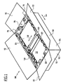
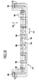
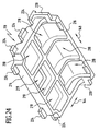
- One in the Fig. 1 to 24 illustrated as a whole with 100 rinsing packaging comprises an outer package 102 in the form of a substantially cuboidal folding carton 104, which comprises a bottom 106, two long side walls 108, two short side walls 110 and at the upper edges of the side walls 108, 110 folding flaps 112 which together form a ceiling wall of the outer packaging 102 in the folded state.
- FIG. 3 to 5 accommodated perspective view from different angles, which two opposing support body 116, a support body 116 interconnecting intermediate element 118 (see Fig. 8 ), a sink 120 disposed between the support bodies 116, a basin cover 122 covering a portion of the top of the sink, a cutting board box 124 resting on the pool cover 122, and a side of the sink 120 remote from the sink 120 between the support bodies 116 and the intermediate element 118 Intermediate element 118 received mixed battery box 126 (see Fig. 5 ).
- each supporting body 116 substantially corresponds to the clear height H of the inner space 114 of the outer packaging 102 in order to prevent vertical movement of the supporting bodies 116 within the outer packaging.
- each support body 116 substantially corresponds to the clear length L of the inner space 114 of the outer package 102 to prevent slippage of the support body 116 within the outer package 102 in the longitudinal direction thereof.
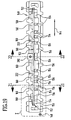
- the packaged sink 120 includes a deep main bowl 128, a shallower auxiliary bowl 130, and a substantially planar, horizontal drainer 132.
- a substantially horizontal sink rim 134 passes around the main bowl 128, the bowl 130 and the drainer 132 and includes two long edge portions 136 which extend parallel to the two long sides of the sink 120 and two short rim portions 138 which extend along the bowl two short sides of the sink 120 extend ( Fig. 7 ).
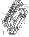
- Each of the two support bodies 116 of the sink package 100 comprises a receiving element 140 and a spacer element 142, wherein the receiving element 140 rests on the upper side of the spacer element 142 and the receiving element 140 and the spacer element 142 have identical shape and orientation.
- the two support bodies 116 of the sink package 100 differ from each other only in that they are rotated by 180 ° about a vertical axis relative to each other.
- the two support bodies 116 of the sink pack 100 thus comprise a total of four elements of identical shape, namely two receiving elements 140 and two spacer elements 142.
- the receiving member 140 is formed as a substantially U-shaped female strip having a central portion 146 extending in the longitudinal direction 144 of the female member 140 and two extending along a transverse direction 148 of the female member 140 which is oriented horizontally and perpendicular to the longitudinal direction 144 End sections 150.
- the receiving element 140 is provided with a receiving channel 152 which is formed by an approximately centrally in the horizontal direction of the sink 120 facing inner sides of the central portion 146 and the end portions 150 extending groove.
- This receiving channel 152 is bounded below by a plurality of support projections 154, which follow one another in the longitudinal direction 144 of the receiving element 140, wherein each two successive support projections 154 by an interposed, extending from the Receiving channel 152 from downwardly extending recess 156 separated from each other and spaced.
- the receiving channel 152 is delimited by a plurality of channel limiting projections 158 which follow one another in the longitudinal direction 144 of the receiving element 140, two channel limiting projections 158 following each other in the longitudinal direction 144 being separated from one another by a respective recess 160 extending upwardly from the receiving channel 152 and are spaced.
- the receiving member 140 When packaging the sink 120, the receiving member 140 is pushed onto the sink rim so that a long edge portion 136 of the sink rim 134 in the central portion of the receiving channel 152 and parts of the short edge portions 138 of the sink rim 134 engage the end portions of the receiving channel 152.
- the sink 120 rests with the underside of the sink edge 143 on the support projections 154 of the receiving element 140.
- the sink 120 is provided on its underside with Garelementhöckern, so it may be provided in particular that the sink 120 is supported on this support member bumps on the support projections 154 of the receiving element 140.
- the receiving element 140 is not pushed onto the rinse edge 134 until the rinse edge 134 rests against the rear side of the receiving channel 152, but only so far until the holding element bumps abut against the respective associated support projections 154.
- the end position of the receiving elements 140 relative to the sink 120 is determined only by the position of the holding element bumps and not by the distance, by which the rinse edge 134 projects beyond the Garelementhöcker to the outside.
- the distance of the two opposing support body 116 of the sink package 100 in this case only on the distance of the opposing Garelementhöcker and not of the total width of the sink (that is, their extension perpendicular to the longitudinal direction of the sink) dependent, whereby it is possible for rinsing 120 different widths to achieve the same width of the sink package 100, so that the same outer package 102 can be used for different widths rinsing.
- the rinse edge 134 is supported only on the support projections 154 and not in the region of the recesses 156 located therebetween on the receiving element 140, so that the rinse edge 134 rests only partially on the receiving element 140.
- the upper side of the rinse edge 134 also comes into contact with the receiving element 140 only in the region of the channel limiting projections 158, but not in the region of the recesses 160 lying therebetween.
- the channel limiting projections 158 on the upper side of the receiving channel 152 lie opposite one of the support projections 154 on the underside of the receiving channel 152.
- the channel limiting projections 158 are arranged offset at the top of the receiving channel 152 relative to the support projections 154 on the underside of the receiving channel 152, that these Kanalbegrenzungsvorsprünge 158 at least partially one of the recesses 156 at the Bottom of the receiving channel 152 are opposite.
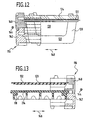
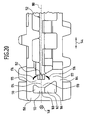
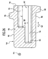
- the end portions 150 of the receiving element 140 are each provided with a cavity 162 which is open only to the end-side end face 164 of the end portion 150.
- the cavity 162 includes a lower portion 166 having a substantially trapezoidal vertical cross-section which widens downwardly toward the inner surface of the end portion 150 toward the sink 120, a central portion 168 substantially contiguous with the lower portion 166 rectangular vertical cross-section and an upper region 170 adjoining the middle region 168 with a substantially trapezoidal vertical cross-section, which widens upwards and towards the inside of the end section 150 facing the sink 120.
- the cross-sectional area of the upper region 170 is significantly smaller than the cross-sectional area of the lower region 166.
- the intermediate central region 168 of the cavity 162 forms a cavity 172 of the cavity formed by the inner wall 174 of the end portion 150 facing the sink 120 projecting into the cavity 162.
- This design of the end portion 150 is achieved that the upper portion 175 of the inner wall 174 and the lower portion 177 of the inner wall 174 upon exertion of pressure on the receiving element 140 slightly to the protruding into the cavity 162 central portion 178 of the inner wall 174 to the through the Central portion 178 extending horizontal plane 180 of the receiving element 140 can be pivoted toward, which has an increased damping effect of the receiving element 140 with respect to acting in the vertical direction on the receiving element 140 impact forces result.
- Fig. 26 and 27 extends the lower portion 166 of the cavity 162 from the end face 164 along the transverse direction 148 by a distance s in the end portion 150 of the receiving member 140 in which is significantly greater than the distance s', around which the upper portion 170 and the central portion 168 of the cavity 162 extend from the end-side end face 164 in the transverse direction 148 into the end portion 150 of the receiving member 140.
- the distance s may in particular be at least 50% greater than the distance s'.
- a step 181 is formed at the rear side of the upper region 170 and the central region 168 of the cavity 162 facing away from the end-side end face 164 of the end section 150 the entire vertical cross-section of the cavity 162 (seen in the direction facing the end-side end face 164) increases abruptly.
- This configuration of the cavity 162 expands the cavity 162 towards the end face 164 of the end portion 150.
- the mechanical stability of the end portion 150 relative to an end portion having a cavity in the transverse direction 148 is constant vertical Cross section increased.
- the vertical cross section of the cavity 162 along the transverse direction 148 is substantially constant.
- the vertical cross-section of the cavity 162 is in the region between the step 181 and the rear side facing away from the end face 164 Boundary surface 183 of the lower portion 166 of the cavity 162 along the transverse direction 148 is substantially constant.
- the receiving element 140 (and thus also the spacer element 142) is provided on its upper side 182 with a plurality of projections 184 extending upwards from the upper side 182.
- the receiving element 140 (and thus also the spacer element 142) is also provided on its underside 186 with a plurality of projections 188 which extend from the bottom 186 downwards.
- the vertical extension of the projections 188 on the underside 186 is substantially the same size as the vertical extent of the projections 184 on the upper side 182, so that when the receiving element 140 is placed on the identically formed spacer element 142, the projections 188 on the underside 186 of the receiving element 140 on the upper side 182 of the spacer element 142 and at the same time abut the projections 184 on the upper side 182 of the spacer element 142 on the underside 186 of the receiving element 140.
- the projections 188 on the bottom 186 and the projections 184 on the top 182 are offset from each other so that when the receiving element 140 is placed on the identically formed spacer element 142, each of the projections 188 on the bottom 186 of Receiving element 140 with one of its inclined against the vertical side surfaces 190 on one of the inclined side surfaces 192 of an adjacently arranged projection 184 on the upper side 182 of the spacer element 142 is flat.
- the projections 184, 188 extend partly transversely to the longitudinal direction 144 and partly transversely to the transverse direction 148 of the receiving element 140, the projections 188 on the underside 186 of the receiving element 140 and the projections 184 on the upper side 182 of the spacer element 142 thus interact with one another in that the receiving element 140 and the spacer element 142 are secured against relative movement both in the longitudinal direction 144 of the receiving element 140 and the spacer element 142 and in the transverse direction 148 of the receiving element 148 and the spacer element 142 and only by a relative movement in the vertical direction from one another can be solved.
- the receiving elements 140 and the spacer elements 142 of the rinse pack 100 are preferably formed as one-piece moldings of a foamed plastic material, in particular of an expanded polystyrene material.
- the sink package 100 further includes the pool cover 122, which rests on top of the sink 120 and covers both the main pool 128 and the auxiliary pool 130 of the sink 120. In this way, a wandering or slipping out of accommodated in the main basin 128 or in the additional basin 130 accessories is prevented.
- the pool cover 122 comprises a substantially rectangular horizontal cover plate 194 and a likewise substantially rectangular vertical support plate 196, which is formed integrally with the horizontal cover plate 194 and along a crease line 198 connects to a Abtrotflansch circuit edge of the horizontal cover plate 194.
- the pool cover 122 is formed of, for example, a cardboard board or a corrugated board.
- the horizontal cover plate 194 is provided at its lateral edges, each with a substantially rectangular recess 200 which is complementary to each one centrally of the sink 120 facing inside of the central portion 146 of a receiving element 146 arranged stop block 202 is formed.
- Each of these stop blocks 202 engages the respective associated recess 200 of the horizontal cover plate 194 and thus secures the pelvic cover 122 against movement relative to the respective receiving element 140 in its longitudinal direction 144 and against movement relative to the two receiving elements 140 in their common transverse direction 148 ,
- a vertical receiving groove 204 is provided in each of the receiving elements 140 on the inside of the central portion 146, in each of which a lateral edge of the vertical holding plate 196 engages.
- the vertical support plate 196 and the receiving grooves 204 of the receiving elements 140 act together so that the pelvic cover 122 is secured against movement relative to the receiving elements 140 in the longitudinal direction 144 and in the transverse direction 148 thereof.
- the vertical support plate 196 and the ceiling wall of the overwrap 102 formed by the flapper pockets 112 cooperate so that the displacement path of the basin cover 122 is limited in the vertical direction.
- the vertical receiving groove 204 preferably extends into one of the projections 184 on the upper side 182 of the receiving element 140, since this increases the vertical extent of the receiving groove 204 and thus the contact surface with the holding plate 196.
- the receiving elements 140 are mirror-symmetrical to their transverse center plane 206, which runs centrally through the stop block 202, the receiving groove 204 for the vertical holding plate 196 of the pelvic cover 122 is present twice on each receiving element 140.
- the horizontal cover plate 194 of the pelvic cover 122 is further provided at its the vertical support plate 196 remote rear free edge with a projection 209 which engages in the space between the end portions 150 of the two receiving elements 140.
- the cutting board box 124 is arranged, which is designed as a substantially cuboid folding box made of cardboard material.
- the width of the cutting board box 124 corresponds to the distance between the inner sides of the central portions 146 of the receiving elements 140, so that the cutting board box 124 is secured by the receiving elements 140 against slipping in the transverse direction 148.
- the cutting board box 124 With its vertical support plate 196 facing front 210, the cutting board box 124 abuts against the stop blocks 202 of the receiving elements 140, so that the displacement of the cutting board box 124 is limited in the direction of the vertical support plate 196 by the stop blocks 202.
- the cutting board box 124 extends to a point 212 (see Fig. 9 ), at which the corner portion of the receiving elements 140 begins and the mutual clear distance of the two opposing receiving elements 140 begins to decrease, so that the displacement of the cutting board box 124 is also limited in the vertical holding plate 196 facing away.
- the cutting board box 124 is thus received substantially free of play between the stop blocks 202 and the corner regions of the receiving elements 140.
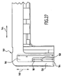
- the sink package 100 further includes the in the Fig. 23 and 24 separately shown angular intermediate member 118, which includes a longer horizontal leg 214 and a shorter vertical leg 216.
- the intermediate element 118 is formed integrally and preferably as a shaped body made of a foamable plastic material, in particular of an expanded polystyrene material.
- the material of the additional element 118 substantially coincides with the material of the receiving elements 140 and the spacer elements 142 of the sink package 100.
- the intermediate member 118 is provided on the underside of the horizontal leg 214 and the sink 120 facing away from the front side of the vertical leg 216 with a plurality of recesses 218 and with an opening 219, which cause a weight saving and an improvement in the shock absorption properties of the intermediate element 118th have as a consequence.
- the vertical leg 216 of the intermediate member 118 is provided at its lateral edges with a respective vertically extending projection 220.
- Each of the receiving elements 140 and thus also each of the spacer elements 142 is provided with a vertical receiving groove 222 corresponding to this projection, which is provided on the inner side of the middle section 146 of the respective receiving element 140 or spacer element 142 facing the sink 120 ( Fig. 19 ).
- the vertical projections 220 of the vertical leg 216 of the intermediate member 118 engage in these vertical grooves 222 of the spacer elements 142, so that by the interaction of the vertical projections 220 and the receiving grooves 222, the intermediate member 118 against movement relative to the Spacer elements 142 is secured in the longitudinal direction 144.
- the horizontal leg 214 of the intermediate member 118 is provided on its longitudinal sides and on its side facing away from the vertical leg 216 with a plurality of horizontal projections 224 which engage in the assembled state of the sink package 100 formed between the receiving element 140 and the spacer element 142 of a support body 116 spaces and thus cooperate with the projections 184 on the upper side 182 of the spacer elements 124 and with the projections 188 on the underside 186 of the receiving elements 140 such that the intermediate element 118 prevents movement relative to the two supporting bodies 116 in the longitudinal direction 144, in the transverse direction 148 and secured in the vertical.
- the intermediate member 118 separates the portion of the sink package 100 in which the sink 120 is housed from another portion of the sink package 100 in which the substantially cuboid mixer box 126 is housed.
- the intermediate member 118 fixed relative to the support bodies 116 of the sink package 100 thus prevents the mixer box 126, contained in the relatively heavy accessories, namely the mixer tap of the sink 120, together with tubing and installation material, in the sink package 100 can slip so that it comes into contact with the sink 120 and the same damaged.
- the packaging of the sink 120 by means of the rinse packaging 100 described above can be carried out according to the procedure described below:
- the spacer elements 142 are connected to each other by means of the intermediate member 118 by the vertical projections 220 of the vertical leg 216 of the intermediate member 118 are inserted into the vertical receiving grooves 222 of the spacer elements 142.
- the mixer box 126 is placed in the interior of the outer package 102 and placed on the bottom 106.
- the arrangement of the spacer elements 142 and the intermediate member 118 is inserted into the interior of the outer package 102 that the spacer elements 142 sit parallel to the long side walls 108 of the outer package 102 aligned longitudinal directions 144 on the bottom 106 of the outer package 102 and the mixer box 126th is fixed by the intermediate element 118 in the desired packaging position within the outer package 102.
- the receiving elements 140 of the support body 116 are laterally pushed onto the edge portions 136, 138 of the sink rim 134 of the sink 120, so that the sink edge 134 engages in the receiving channels 152 of the receiving elements 140.
- the pelvic cover 122 After attaching the receiving elements 140, the pelvic cover 122 is placed on top of the sink 120 by first pushing the rear free edge of the horizontal cover plate 194 of the pelvic cover 122 under the protrusions 208 on the end portions 150 of the receptacles 140, the pelvis cover 122 thus inclined to the horizontal, that the vertical support plate 196 is above the receiving elements 140, and then the pelvic cover 122 is pivoted about the rear free edge of the horizontal cover plate 194 down that the vertical support plate 196 of the pelvic cover 122 in the hereby corresponding Receiving grooves 204 of the receiving elements 140 engages until the pelvic cover 122 rests on the top of the sink 120 and the main basin 128 and the additional basin 130 covered.
- the arrangement of the sink 120, the receiving elements 140 and the basin cover 122 is introduced vertically from above into the interior 114 of the outer packaging 102 and with the lower sides 186 of the receiving elements 140 on the upper sides 182 of the spacer elements 142 deposed.
- the cutting board box 124 is placed on the pelvic cover 122 so that it rests against the stop blocks 202 of the receiving elements 140.
- folding pockets 112 of the outer packaging 102 are folded in order to form a closed ceiling wall of the outer packaging 102, which is permanently closed and ready for transport, for example by means of adhesive strips or strapping made of a band-shaped material.
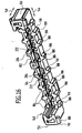
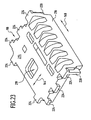
- the same receiving elements 140 of the supporting bodies 116 of the rinsing pack 100 described above can be stacked directly on one another, the same receiving elements 140 can also be used to produce a stack 224 of rinses 120, as in FIG Fig. 25 is shown.
- two receiving elements 140 which are formed exactly like the receiving elements 140 described above, are pushed onto mutually opposite edge sections of the rinsing edge 134 of the respective sink 120, so that the edge sections 136, 138 of the rinsing edge 134 in FIG the receiving channels 152 of the receiving elements 140 engage.
- the receiving elements 140 are fixed to the sink 120, for example by means of adhesive strips and / or by means of a strapping of a strip material.
- a plurality of rinses 120 with the receiving elements 140 arranged thereon are stacked on one another by the receiving elements 140 connected to a sink 120a each being placed vertically from above onto the receiving elements 140 of a sink 120b arranged thereunder until the receiving elements 140 of the upper sink 120a with its lower side 186 rest on the upper side 182 of the receiving elements 140 of the lower sink 120b, as shown in FIG Fig. 25 is shown.
- the main basin 128 and the additional basin 130 of the upper sink 120a submerge in the main basin 128 or in the additional basin 130 of the lower sink 120b, so that the stack height per sink, that is, the vertical spacing of the sink rims 134 in the stack 224, is lower is greater than the height of a sink 120.
- the sinks 120 can be arranged in a particularly space-saving manner in the form of the stack 224 and stored in this arrangement, for example, before a single transport in an outer package 102.
- the rinsings 120 stored in the stack 224 can be packaged individually in an outer packaging 102 without prior removal of the receiving elements 140 and thus particularly time-saving be reduced, and also the number of required for the storage in the stack 224 and for the subsequent individual packaging of the sinks 120 in each case a rinse packaging 100 packaging elements.
Landscapes
- Engineering & Computer Science (AREA)
- Mechanical Engineering (AREA)
- Buffer Packaging (AREA)
- Packging For Living Organisms, Food Or Medicinal Products That Are Sensitive To Environmental Conditiond (AREA)
- Addition Polymer Or Copolymer, Post-Treatments, Or Chemical Modifications (AREA)
Priority Applications (8)
| Application Number | Priority Date | Filing Date | Title |
|---|---|---|---|
| DE502004007001T DE502004007001D1 (de) | 2004-05-29 | 2004-05-29 | Verpackung für eine Spüle |
| AT04012865T ATE393745T1 (de) | 2004-05-29 | 2004-05-29 | Verpackung für eine spüle |
| PL04012865T PL1600403T3 (pl) | 2004-05-29 | 2004-05-29 | Opakowanie dla zlewozmywaka |
| EP04012865A EP1600403B1 (de) | 2004-05-29 | 2004-05-29 | Verpackung für eine Spüle |
| ES04012865T ES2303002T3 (es) | 2004-05-29 | 2004-05-29 | Embalaje para un fregadero. |
| SI200430761T SI1600403T1 (sl) | 2004-05-29 | 2004-05-29 | Embalaĺ˝a za pomivalno korito |
| US10/872,855 US7240792B2 (en) | 2004-05-29 | 2004-06-21 | Packaging for a sink |
| US11/759,094 US7753208B2 (en) | 2004-05-29 | 2007-06-06 | Packaging for a sink |
Applications Claiming Priority (1)
| Application Number | Priority Date | Filing Date | Title |
|---|---|---|---|
| EP04012865A EP1600403B1 (de) | 2004-05-29 | 2004-05-29 | Verpackung für eine Spüle |
Publications (2)
| Publication Number | Publication Date |
|---|---|
| EP1600403A1 EP1600403A1 (de) | 2005-11-30 |
| EP1600403B1 true EP1600403B1 (de) | 2008-04-30 |
Family
ID=34925197
Family Applications (1)
| Application Number | Title | Priority Date | Filing Date |
|---|---|---|---|
| EP04012865A Expired - Lifetime EP1600403B1 (de) | 2004-05-29 | 2004-05-29 | Verpackung für eine Spüle |
Country Status (6)
| Country | Link |
|---|---|
| EP (1) | EP1600403B1 (sl) |
| AT (1) | ATE393745T1 (sl) |
| DE (1) | DE502004007001D1 (sl) |
| ES (1) | ES2303002T3 (sl) |
| PL (1) | PL1600403T3 (sl) |
| SI (1) | SI1600403T1 (sl) |
Families Citing this family (7)
| Publication number | Priority date | Publication date | Assignee | Title |
|---|---|---|---|---|
| DE102005042671A1 (de) * | 2005-09-08 | 2007-03-29 | Blanco Gmbh + Co Kg | Verpackung für eine Spüle |
| DE102006016152A1 (de) * | 2006-04-06 | 2007-10-11 | Blanco Gmbh + Co Kg | Transportverpackung für ein Transportgut |
| ITMI20081935A1 (it) * | 2008-11-03 | 2010-05-04 | Orsey Venture Llc | Intercapedine di imballaggio ritornabile, nonché contenitore ritornabile comprendente tale intercapedine |
| EP2208683B1 (de) | 2009-01-14 | 2011-11-02 | BLANCO GmbH + Co KG | Verpackung für eine Spüle |
| EP2208688B1 (de) | 2009-01-14 | 2011-11-02 | BLANCO GmbH + Co KG | Verpackung für eine Spüle |
| DE102011117092A1 (de) * | 2011-10-21 | 2013-04-25 | Kärcher Futuretech GmbH | Transportables,modulares Küchensystem zur Verpflegung einer Vielzahl von Menschen |
| DE102013019661A1 (de) * | 2013-11-19 | 2015-05-21 | Schock Gmbh | Beckentransporteinheit, insbesondere Spülbeckentransporteinheit |
Family Cites Families (5)
| Publication number | Priority date | Publication date | Assignee | Title |
|---|---|---|---|---|
| DE1920893A1 (de) * | 1969-04-24 | 1970-11-12 | Dual Gebrueder Steidinger | Verpackungseinlage-Formteil |
| US4584822A (en) * | 1984-03-07 | 1986-04-29 | Sealed Air Corporation | Method of packing objects and packing therefor |
| JPS63272682A (ja) * | 1987-04-21 | 1988-11-10 | Matsushita Electric Ind Co Ltd | 包装装置 |
| JP2932367B2 (ja) * | 1996-07-17 | 1999-08-09 | 東洋實業株式会社 | カウンター包装体 |
| US6382422B1 (en) * | 2000-09-13 | 2002-05-07 | Hewlett-Packard Company | Packaging system for a family of products |
-
2004
- 2004-05-29 SI SI200430761T patent/SI1600403T1/sl unknown
- 2004-05-29 DE DE502004007001T patent/DE502004007001D1/de not_active Expired - Lifetime
- 2004-05-29 PL PL04012865T patent/PL1600403T3/pl unknown
- 2004-05-29 ES ES04012865T patent/ES2303002T3/es not_active Expired - Lifetime
- 2004-05-29 AT AT04012865T patent/ATE393745T1/de not_active IP Right Cessation
- 2004-05-29 EP EP04012865A patent/EP1600403B1/de not_active Expired - Lifetime
Also Published As
| Publication number | Publication date |
|---|---|
| ES2303002T3 (es) | 2008-08-01 |
| DE502004007001D1 (de) | 2008-06-12 |
| PL1600403T3 (pl) | 2008-10-31 |
| ATE393745T1 (de) | 2008-05-15 |
| EP1600403A1 (de) | 2005-11-30 |
| SI1600403T1 (sl) | 2008-10-31 |
Similar Documents
| Publication | Publication Date | Title |
|---|---|---|
| EP1131249B1 (de) | Behälter aus mehreren platten | |
| DE2643720C2 (de) | Stapelbarer Transportbehälter | |
| DE8609673U1 (de) | Falt- und stapelbarer Karton aus Pappe | |
| EP1600403B1 (de) | Verpackung für eine Spüle | |
| DE3840996C2 (sl) | ||
| EP3216722A1 (de) | Spülbeckenverpackung | |
| EP0575394B1 (de) | Behälteranordnung | |
| EP1035026A1 (de) | Stapelbare Verpackung | |
| DE3806069C2 (de) | Palette | |
| EP1600401A1 (de) | Verpackung für eine Spüle | |
| EP1880950B1 (de) | Verpackung für ein Transportgut | |
| DE202004001382U1 (de) | Mehrwege-Box | |
| EP0357817B1 (de) | Holzregal mit auf unterschiedlichen Höhen anbringbaren Einlegeböden | |
| EP3543158B1 (de) | Transportbehälter | |
| WO1986005159A1 (en) | Crate | |
| DE2714623A1 (de) | Stapelbare steige | |
| EP2208688B1 (de) | Verpackung für eine Spüle | |
| EP2208683B1 (de) | Verpackung für eine Spüle | |
| DE202004021443U1 (de) | Verpackung für eine Spüle | |
| DE3729596A1 (de) | Verpackungsschale oder steige aus pappe zum verpacken von produkten, vorzugsweise von landwirtschaftlichen produkten | |
| DE2731781B2 (de) | Stützfuß aus Kunststoff für Kartons o.dgl | |
| AT522769B1 (de) | Faltkiste | |
| DE3938297C2 (sl) | ||
| EP1145985B1 (de) | Stapeltransportverpackung für eine Spüle | |
| EP2987742B1 (de) | Stapelbarer behälter mit lastübertragungsstruktur |
Legal Events
| Date | Code | Title | Description |
|---|---|---|---|
| PUAI | Public reference made under article 153(3) epc to a published international application that has entered the european phase |
Free format text: ORIGINAL CODE: 0009012 |
|
| AK | Designated contracting states |
Kind code of ref document: A1 Designated state(s): AT BE BG CH CY CZ DE DK EE ES FI FR GB GR HU IE IT LI LU MC NL PL PT RO SE SI SK TR |
|
| AX | Request for extension of the european patent |
Extension state: AL HR LT LV MK |
|
| 17P | Request for examination filed |
Effective date: 20060209 |
|
| AKX | Designation fees paid |
Designated state(s): AT BE BG CH CY CZ DE DK EE ES FI FR GB GR HU IE IT LI LU MC NL PL PT RO SE SI SK TR |
|
| 17Q | First examination report despatched |
Effective date: 20070221 |
|
| GRAP | Despatch of communication of intention to grant a patent |
Free format text: ORIGINAL CODE: EPIDOSNIGR1 |
|
| GRAS | Grant fee paid |
Free format text: ORIGINAL CODE: EPIDOSNIGR3 |
|
| GRAA | (expected) grant |
Free format text: ORIGINAL CODE: 0009210 |
|
| AK | Designated contracting states |
Kind code of ref document: B1 Designated state(s): AT BE BG CH CY CZ DE DK EE ES FI FR GB GR HU IE IT LI LU MC NL PL PT RO SE SI SK TR |
|
| REG | Reference to a national code |
Ref country code: GB Ref legal event code: FG4D Free format text: NOT ENGLISH |
|
| REG | Reference to a national code |
Ref country code: CH Ref legal event code: EP Ref country code: CH Ref legal event code: NV Representative=s name: ISLER & PEDRAZZINI AG |
|
| REG | Reference to a national code |
Ref country code: IE Ref legal event code: FG4D Free format text: LANGUAGE OF EP DOCUMENT: GERMAN |
|
| REF | Corresponds to: |
Ref document number: 502004007001 Country of ref document: DE Date of ref document: 20080612 Kind code of ref document: P |
|
| REG | Reference to a national code |
Ref country code: ES Ref legal event code: FG2A Ref document number: 2303002 Country of ref document: ES Kind code of ref document: T3 |
|
| NLV1 | Nl: lapsed or annulled due to failure to fulfill the requirements of art. 29p and 29m of the patents act | ||
| PG25 | Lapsed in a contracting state [announced via postgrant information from national office to epo] |
Ref country code: NL Free format text: LAPSE BECAUSE OF FAILURE TO SUBMIT A TRANSLATION OF THE DESCRIPTION OR TO PAY THE FEE WITHIN THE PRESCRIBED TIME-LIMIT Effective date: 20080430 Ref country code: FI Free format text: LAPSE BECAUSE OF FAILURE TO SUBMIT A TRANSLATION OF THE DESCRIPTION OR TO PAY THE FEE WITHIN THE PRESCRIBED TIME-LIMIT Effective date: 20080430 Ref country code: PT Free format text: LAPSE BECAUSE OF FAILURE TO SUBMIT A TRANSLATION OF THE DESCRIPTION OR TO PAY THE FEE WITHIN THE PRESCRIBED TIME-LIMIT Effective date: 20080930 Ref country code: BG Free format text: LAPSE BECAUSE OF FAILURE TO SUBMIT A TRANSLATION OF THE DESCRIPTION OR TO PAY THE FEE WITHIN THE PRESCRIBED TIME-LIMIT Effective date: 20080730 |
|
| REG | Reference to a national code |
Ref country code: PL Ref legal event code: T3 |
|
| BERE | Be: lapsed |
Owner name: BLANCO G.M.B.H. + CO KG Effective date: 20080531 |
|
| REG | Reference to a national code |
Ref country code: IE Ref legal event code: FD4D |
|
| PG25 | Lapsed in a contracting state [announced via postgrant information from national office to epo] |
Ref country code: MC Free format text: LAPSE BECAUSE OF NON-PAYMENT OF DUE FEES Effective date: 20080531 |
|
| ET | Fr: translation filed | ||
| PG25 | Lapsed in a contracting state [announced via postgrant information from national office to epo] |
Ref country code: DK Free format text: LAPSE BECAUSE OF FAILURE TO SUBMIT A TRANSLATION OF THE DESCRIPTION OR TO PAY THE FEE WITHIN THE PRESCRIBED TIME-LIMIT Effective date: 20080430 Ref country code: SE Free format text: LAPSE BECAUSE OF FAILURE TO SUBMIT A TRANSLATION OF THE DESCRIPTION OR TO PAY THE FEE WITHIN THE PRESCRIBED TIME-LIMIT Effective date: 20080731 Ref country code: CZ Free format text: LAPSE BECAUSE OF FAILURE TO SUBMIT A TRANSLATION OF THE DESCRIPTION OR TO PAY THE FEE WITHIN THE PRESCRIBED TIME-LIMIT Effective date: 20080430 Ref country code: IE Free format text: LAPSE BECAUSE OF FAILURE TO SUBMIT A TRANSLATION OF THE DESCRIPTION OR TO PAY THE FEE WITHIN THE PRESCRIBED TIME-LIMIT Effective date: 20080430 |
|
| PG25 | Lapsed in a contracting state [announced via postgrant information from national office to epo] |
Ref country code: SK Free format text: LAPSE BECAUSE OF FAILURE TO SUBMIT A TRANSLATION OF THE DESCRIPTION OR TO PAY THE FEE WITHIN THE PRESCRIBED TIME-LIMIT Effective date: 20080430 Ref country code: RO Free format text: LAPSE BECAUSE OF FAILURE TO SUBMIT A TRANSLATION OF THE DESCRIPTION OR TO PAY THE FEE WITHIN THE PRESCRIBED TIME-LIMIT Effective date: 20080430 |
|
| PLBE | No opposition filed within time limit |
Free format text: ORIGINAL CODE: 0009261 |
|
| STAA | Information on the status of an ep patent application or granted ep patent |
Free format text: STATUS: NO OPPOSITION FILED WITHIN TIME LIMIT |
|
| PG25 | Lapsed in a contracting state [announced via postgrant information from national office to epo] |
Ref country code: BE Free format text: LAPSE BECAUSE OF NON-PAYMENT OF DUE FEES Effective date: 20080531 |
|
| 26N | No opposition filed |
Effective date: 20090202 |
|
| PG25 | Lapsed in a contracting state [announced via postgrant information from national office to epo] |
Ref country code: EE Free format text: LAPSE BECAUSE OF FAILURE TO SUBMIT A TRANSLATION OF THE DESCRIPTION OR TO PAY THE FEE WITHIN THE PRESCRIBED TIME-LIMIT Effective date: 20080430 |
|
| PG25 | Lapsed in a contracting state [announced via postgrant information from national office to epo] |
Ref country code: IT Free format text: LAPSE BECAUSE OF FAILURE TO SUBMIT A TRANSLATION OF THE DESCRIPTION OR TO PAY THE FEE WITHIN THE PRESCRIBED TIME-LIMIT Effective date: 20080430 Ref country code: AT Free format text: LAPSE BECAUSE OF NON-PAYMENT OF DUE FEES Effective date: 20080529 |
|
| PG25 | Lapsed in a contracting state [announced via postgrant information from national office to epo] |
Ref country code: HU Free format text: LAPSE BECAUSE OF FAILURE TO SUBMIT A TRANSLATION OF THE DESCRIPTION OR TO PAY THE FEE WITHIN THE PRESCRIBED TIME-LIMIT Effective date: 20081101 Ref country code: LU Free format text: LAPSE BECAUSE OF NON-PAYMENT OF DUE FEES Effective date: 20080529 Ref country code: CY Free format text: LAPSE BECAUSE OF FAILURE TO SUBMIT A TRANSLATION OF THE DESCRIPTION OR TO PAY THE FEE WITHIN THE PRESCRIBED TIME-LIMIT Effective date: 20080430 |
|
| PG25 | Lapsed in a contracting state [announced via postgrant information from national office to epo] |
Ref country code: TR Free format text: LAPSE BECAUSE OF FAILURE TO SUBMIT A TRANSLATION OF THE DESCRIPTION OR TO PAY THE FEE WITHIN THE PRESCRIBED TIME-LIMIT Effective date: 20080430 |
|
| PG25 | Lapsed in a contracting state [announced via postgrant information from national office to epo] |
Ref country code: GR Free format text: LAPSE BECAUSE OF FAILURE TO SUBMIT A TRANSLATION OF THE DESCRIPTION OR TO PAY THE FEE WITHIN THE PRESCRIBED TIME-LIMIT Effective date: 20080731 |
|
| PGFP | Annual fee paid to national office [announced via postgrant information from national office to epo] |
Ref country code: CH Payment date: 20120514 Year of fee payment: 9 |
|
| PGFP | Annual fee paid to national office [announced via postgrant information from national office to epo] |
Ref country code: SI Payment date: 20120412 Year of fee payment: 9 |
|
| PGFP | Annual fee paid to national office [announced via postgrant information from national office to epo] |
Ref country code: ES Payment date: 20120607 Year of fee payment: 9 |
|
| PGFP | Annual fee paid to national office [announced via postgrant information from national office to epo] |
Ref country code: GB Payment date: 20130529 Year of fee payment: 10 Ref country code: DE Payment date: 20130626 Year of fee payment: 10 |
|
| PGFP | Annual fee paid to national office [announced via postgrant information from national office to epo] |
Ref country code: FR Payment date: 20130531 Year of fee payment: 10 Ref country code: PL Payment date: 20130415 Year of fee payment: 10 |
|
| REG | Reference to a national code |
Ref country code: CH Ref legal event code: PL |
|
| PG25 | Lapsed in a contracting state [announced via postgrant information from national office to epo] |
Ref country code: LI Free format text: LAPSE BECAUSE OF NON-PAYMENT OF DUE FEES Effective date: 20130531 Ref country code: CH Free format text: LAPSE BECAUSE OF NON-PAYMENT OF DUE FEES Effective date: 20130531 |
|
| REG | Reference to a national code |
Ref country code: SI Ref legal event code: KO00 Effective date: 20140205 |
|
| PG25 | Lapsed in a contracting state [announced via postgrant information from national office to epo] |
Ref country code: SI Free format text: LAPSE BECAUSE OF NON-PAYMENT OF DUE FEES Effective date: 20130530 |
|
| REG | Reference to a national code |
Ref country code: ES Ref legal event code: FD2A Effective date: 20140613 |
|
| PG25 | Lapsed in a contracting state [announced via postgrant information from national office to epo] |
Ref country code: ES Free format text: LAPSE BECAUSE OF NON-PAYMENT OF DUE FEES Effective date: 20130530 |
|
| REG | Reference to a national code |
Ref country code: DE Ref legal event code: R119 Ref document number: 502004007001 Country of ref document: DE |
|
| GBPC | Gb: european patent ceased through non-payment of renewal fee |
Effective date: 20140529 |
|
| REG | Reference to a national code |
Ref country code: DE Ref legal event code: R119 Ref document number: 502004007001 Country of ref document: DE Effective date: 20141202 |
|
| REG | Reference to a national code |
Ref country code: FR Ref legal event code: ST Effective date: 20150130 |
|
| PG25 | Lapsed in a contracting state [announced via postgrant information from national office to epo] |
Ref country code: DE Free format text: LAPSE BECAUSE OF NON-PAYMENT OF DUE FEES Effective date: 20141202 |
|
| PG25 | Lapsed in a contracting state [announced via postgrant information from national office to epo] |
Ref country code: GB Free format text: LAPSE BECAUSE OF NON-PAYMENT OF DUE FEES Effective date: 20140529 Ref country code: FR Free format text: LAPSE BECAUSE OF NON-PAYMENT OF DUE FEES Effective date: 20140602 |
|
| PG25 | Lapsed in a contracting state [announced via postgrant information from national office to epo] |
Ref country code: PL Free format text: LAPSE BECAUSE OF NON-PAYMENT OF DUE FEES Effective date: 20140529 |
|
| REG | Reference to a national code |
Ref country code: PL Ref legal event code: LAPE |