EP1600403B1 - Packing for a sink - Google Patents
Packing for a sink Download PDFInfo
- Publication number
- EP1600403B1 EP1600403B1 EP04012865A EP04012865A EP1600403B1 EP 1600403 B1 EP1600403 B1 EP 1600403B1 EP 04012865 A EP04012865 A EP 04012865A EP 04012865 A EP04012865 A EP 04012865A EP 1600403 B1 EP1600403 B1 EP 1600403B1
- Authority
- EP
- European Patent Office
- Prior art keywords
- receiving element
- sink
- packaging according
- receiving
- packaging
- Prior art date
- Legal status (The legal status is an assumption and is not a legal conclusion. Google has not performed a legal analysis and makes no representation as to the accuracy of the status listed.)
- Not-in-force
Links
Images


Classifications
-
- B—PERFORMING OPERATIONS; TRANSPORTING
- B65—CONVEYING; PACKING; STORING; HANDLING THIN OR FILAMENTARY MATERIAL
- B65D—CONTAINERS FOR STORAGE OR TRANSPORT OF ARTICLES OR MATERIALS, e.g. BAGS, BARRELS, BOTTLES, BOXES, CANS, CARTONS, CRATES, DRUMS, JARS, TANKS, HOPPERS, FORWARDING CONTAINERS; ACCESSORIES, CLOSURES, OR FITTINGS THEREFOR; PACKAGING ELEMENTS; PACKAGES
- B65D5/00—Rigid or semi-rigid containers of polygonal cross-section, e.g. boxes, cartons or trays, formed by folding or erecting one or more blanks made of paper
- B65D5/42—Details of containers or of foldable or erectable container blanks
- B65D5/44—Integral, inserted or attached portions forming internal or external fittings
- B65D5/50—Internal supporting or protecting elements for contents
- B65D5/5028—Elements formed separately from the container body
- B65D5/5088—Plastic elements
- B65D5/509—Foam plastic elements
-
- B—PERFORMING OPERATIONS; TRANSPORTING
- B65—CONVEYING; PACKING; STORING; HANDLING THIN OR FILAMENTARY MATERIAL
- B65D—CONTAINERS FOR STORAGE OR TRANSPORT OF ARTICLES OR MATERIALS, e.g. BAGS, BARRELS, BOTTLES, BOXES, CANS, CARTONS, CRATES, DRUMS, JARS, TANKS, HOPPERS, FORWARDING CONTAINERS; ACCESSORIES, CLOSURES, OR FITTINGS THEREFOR; PACKAGING ELEMENTS; PACKAGES
- B65D81/00—Containers, packaging elements, or packages, for contents presenting particular transport or storage problems, or adapted to be used for non-packaging purposes after removal of contents
- B65D81/02—Containers, packaging elements, or packages, for contents presenting particular transport or storage problems, or adapted to be used for non-packaging purposes after removal of contents specially adapted to protect contents from mechanical damage
- B65D81/05—Containers, packaging elements, or packages, for contents presenting particular transport or storage problems, or adapted to be used for non-packaging purposes after removal of contents specially adapted to protect contents from mechanical damage maintaining contents at spaced relation from package walls, or from other contents
- B65D81/107—Containers, packaging elements, or packages, for contents presenting particular transport or storage problems, or adapted to be used for non-packaging purposes after removal of contents specially adapted to protect contents from mechanical damage maintaining contents at spaced relation from package walls, or from other contents using blocks of shock-absorbing material
- B65D81/113—Containers, packaging elements, or packages, for contents presenting particular transport or storage problems, or adapted to be used for non-packaging purposes after removal of contents specially adapted to protect contents from mechanical damage maintaining contents at spaced relation from package walls, or from other contents using blocks of shock-absorbing material of a shape specially adapted to accommodate contents
-
- B—PERFORMING OPERATIONS; TRANSPORTING
- B65—CONVEYING; PACKING; STORING; HANDLING THIN OR FILAMENTARY MATERIAL
- B65D—CONTAINERS FOR STORAGE OR TRANSPORT OF ARTICLES OR MATERIALS, e.g. BAGS, BARRELS, BOTTLES, BOXES, CANS, CARTONS, CRATES, DRUMS, JARS, TANKS, HOPPERS, FORWARDING CONTAINERS; ACCESSORIES, CLOSURES, OR FITTINGS THEREFOR; PACKAGING ELEMENTS; PACKAGES
- B65D85/00—Containers, packaging elements or packages, specially adapted for particular articles or materials
- B65D85/64—Containers, packaging elements or packages, specially adapted for particular articles or materials for bulky articles
-
- B—PERFORMING OPERATIONS; TRANSPORTING
- B65—CONVEYING; PACKING; STORING; HANDLING THIN OR FILAMENTARY MATERIAL
- B65D—CONTAINERS FOR STORAGE OR TRANSPORT OF ARTICLES OR MATERIALS, e.g. BAGS, BARRELS, BOTTLES, BOXES, CANS, CARTONS, CRATES, DRUMS, JARS, TANKS, HOPPERS, FORWARDING CONTAINERS; ACCESSORIES, CLOSURES, OR FITTINGS THEREFOR; PACKAGING ELEMENTS; PACKAGES
- B65D2585/00—Containers, packaging elements or packages specially adapted for particular articles or materials
- B65D2585/64—Containers, packaging elements or packages specially adapted for particular articles or materials for bulky articles
- B65D2585/641—Containers, packaging elements or packages specially adapted for particular articles or materials for bulky articles specific articles
- B65D2585/645—Containers, packaging elements or packages specially adapted for particular articles or materials for bulky articles specific articles kitchen sinks
Definitions
- the present invention relates to a package for a sink according to the preamble of claim 1.
- a package for a sink in which two receiving strips of foamed material on the short longitudinal sides of the edge of a sink, which comprises two equal size sinks, are postponed.
- a cross-sectionally U-shaped bar protection is placed from above on the arranged between the two basins gutter, and the two basins are supported downwards by a substantially T-shaped support body, which under the pool floors and under the two Basin separating divider is arranged.
- This known rinse packaging thus comprises four molded bodies made of foamed plastic material, which are arranged separately from one another on the sink and are not in contact with each other.
- the DE-A-1 920 893 discloses a packaging insert molding made of polystyrene foam or similar material for supporting a device or a device which is supported by a plate with raised edge in a packaging container up and down, wherein the molding contains a slot of a certain depth, with which it on the Edge region of the plate can be pushed, wherein the slot width corresponds approximately to the thickness of the plate and the lateral connection between the parts above and below the slot is designed to be elastic so that the surfaces of the slot can move so far in the direction of the slot depth at least on a part of the slot length that they no longer face each other in cover.
- the present invention has for its object to provide a package for a sink, which has particularly good damping properties and low transport damage rate.
- a package for a sink comprising at least one support body, in turn, at least one receiving element with a receiving channel for an edge portion of the sink and at least one separately formed by the receiving element spacer element which supports the receiving element, wherein the Receiving element and / or the spacer element is at least partially formed of a foamed plastic material.
- the receiving element receiving the edge section of the sink is in direct contact with the spacer element supporting the receiving element, a particularly high damping effect is achieved against impacts acting on the rinse packaging from the outside.
- the support body of the sink package according to the invention is not integrally formed, but comprises two separate elements which are in contact with each other at least one contact surface, it is achieved that impact stresses can not spread undisturbed through the entire support body, as in a one-piece support body of Case is, but rather takes place by the transition from the one element to the other element of the support body at the contact surface an additional damping of shocks.
- the spacer element can sit in particular on the bottom of an outer packaging of the sink package.
- the receiving element and / or the spacer element of the support body are at least partially, preferably completely, formed of a foamed plastic material, a much better Damping effect achieved, for example, when using packaging elements made of corrugated cardboard.
- the rinse packaging according to the invention is particularly suitable for the packaging of particularly fragile rinses, for example of ceramic and / or composite materials.
- the rinsing packaging according to the invention makes it possible to package rinses in a particularly cost-effective and process-reliable manner.
- the receiving channel of the receiving element is designed to receive an edge portion on a long side of the sink.
- the receiving channel of the receiving element is designed to receive an edge portion of the sink, which extends over the entire length of one side of the sink, preferably a long side of the sink.
- the edge portion of the sink is particularly well protected by the rinse wrap when the receiving channel of the receiving member for receiving a rim portion of the sink, which extends along a first side of the sink, and for receiving a rim portion of the sink, which extends along a second side of the sink , is trained.
- the receiving channel of the receiving element is further designed to receive an edge portion of the sink, which extends along a third side of the sink.
- the receiving channel of the receiving element is designed to receive at least one corner region of the edge of the sink.
- the spacer element of the support body has the same shape as the receiving element of the support body.
- the packaging comprises at least two support bodies, each comprising at least one receiving element with a receiving channel for an edge portion of the sink and at least one separately formed from the receiving element spacer element, which supports the respective associated receiving element.
- the same comprises two support bodies which comprise a total of two receiving elements and two spacer elements, all four of these elements being the same Have shape, so that all these elements can be interchanged within the package and only a tool for producing all these elements is required.
- the at least two support bodies of the packaging are arranged on opposite edge portions of the sink.
- the at least one basin of the sink sits on no element of the package.
- the packaging further comprises an outer packaging whose interior receives the sink and the at least one support body.
- This outer packaging may be formed in particular substantially cuboid.
- the outer packaging comprises a folding carton.
- the at least one support body extends over substantially the entire clear height of the interior of the outer packaging extends. In this way, the displacement path of the support body supporting the sink is reduced in the vertical direction during transport of the package and prevents the sink abuts against the outer packaging.
- a support body which extends over substantially the entire clear height of the interior of the outer packaging a support body to understand the height (vertical extent) is at least 90 percent of the clear height H of the interior.
- the height of the support body is at least 95 percent of the total clear height of the interior of the outer packaging.
- the receiving element of the rinsing packaging according to the invention can be designed in particular as a receiving strip.
- the receiving element is formed substantially L-shaped, so only the position of a corner region of the sink edge is set relative to the receiving element, while the free ends of the legs of the L-shaped receiving element from the other corner regions of the edge of the sink to basically any distances could be.
- Such a receiving element can thus be used for packaging arbitrarily wide and arbitrarily long rinsing.
- the receiving element is formed substantially U-shaped.
- the position of the receiving element with respect to two corner regions of the rinse edge is fixed.
- the distance between the free ends of the U-shaped receiving element of the other two corner regions of the sink edge is basically arbitrary, so that such a U-shaped receiving element for the packaging of sinks with a predetermined within a tolerance interval length, but different width can be used.
- the tolerance interval is determined by the depth of the receiving channel in the end regions of the U-shaped receiving element, ie by its extension in the transverse direction of the receiving element, and allows rinsing with varying within the tolerance interval lengths to pack by means of the same receiving elements, said receiving elements with their mid-sections are pushed onto the long sides of the sinks.
- Such a U-shaped receiving element for the packaging of rinses with a predetermined within a tolerance interval width are used.
- the tolerance interval is determined by the depth of the receiving channel in the end regions of the U-shaped receiving element, d. H. by its extension in the transverse direction of the receiving element, determines and allows to pack rinses with varying widths within the tolerance interval by means of the same receiving elements, these receiving elements are pushed with their central regions on the short sides of the sinks.
- the receiving element comprises a longitudinal portion which extends in the longitudinal direction of the sink.
- the receiving element comprises at least one transverse section which extends in the transverse direction of the sink.
- the transverse section ends at a distance from the longitudinal center plane of the sink, so that it is avoided that the free ends of the receiving elements of opposing support body come into contact with each other.
- Particularly good damping properties of the receiving element are achieved when the receiving channel of the receiving element is bounded above and / or down by a plurality Kanalbegrenzungsvorsprünge, which are spaced apart in the longitudinal direction of the receiving channel, so that the sink only at the Kanalbegrenzungsvorsprüngen, but not in the between the channel limiting projections lying areas comes into contact with the receiving element.
- the receiving element comprises at least one end portion which is provided with at least one cavity.
- a particularly good elastic deformability and thus a particularly good damping effect of the end portion of the receiving element is achieved when the cavity has a vertical cross section having a constriction.
- An end portion of the receiving member with good damping effect and yet high stability is obtained when the cavity formed in the end portion widens toward an end face of the end portion.
- the cavity in this case has a vertical cross section varying in the longitudinal direction of the end portion.
- the variation of the vertical cross section can take place continuously or else in one or more discrete steps.
- the end portion provided with the cavity is provided on its side facing the sink with a recess (for example, the receiving channel), whereby the deformability of the end portion is increased under the action of a shock load.
- the receiving element may be provided on its upper side with projections which come to rest on a top wall of the outer packaging of the sink package, so that impacts from the outer packaging on the receiving element not over the entire top of the receiving element, but only on the one another in the longitudinal direction of the receiving element spaced projections can be transferred to the receiving element.
- the spacer element is provided on its underside with projections which come to rest on a bottom wall of the outer packaging of the sink package, so that shocks from the bottom wall of the outer packaging not over the entire bottom of the spacer element, but only on in the Longitudinal direction of the spacer element spaced apart projections can be transferred to the spacer element.
- the receiving element is provided on its underside with projections and / or with recesses and the spacer element provided on its upper side with projections and / or recesses and the protrusions and / or the recesses on the underside of the receiving element so cooperate with the projections and / or the recesses on the upper side of the spacer element that the patch on the spacer element Receiving element is fixed in its longitudinal direction and / or in a direction transverse to its longitudinal direction horizontal transverse direction relative to the spacer element.
- This embodiment contributes to an increased stability of the support body, which is formed from the receiving element and the spacer element, at, since in this case the receiving element and the spacer element can only be solved by a vertically extending relative movement of each other.
- the same comprises a covering element which covers at least part of the sink upwards.
- the cover at least covers a basin of the sink upwards. In this way, a walk or slipping out of this sink of the sink accommodated accessories is prevented.
- the cover does not extend over the entire top of the sink.
- the cover is so engaged with the receiving element that its displacement path is limited relative to the receiving element in the vertical direction, preferably at most about 3 cm.
- the cover member may comprise a substantially horizontal cover portion and a transverse, preferably substantially perpendicular, aligned to the cover portion holding portion.
- the packaging according to the invention may further comprise at least one accessory box, for example a cutting board box, it being favorable if the receiving element has at least one stop limiting the displacement path of the accessory box relative to the receiving element in the longitudinal direction of the receiving element. This prevents slippage of the accessory box during transport in the longitudinal direction of the receiving element.
- at least one accessory box for example a cutting board box
- the package comprises two supporting bodies with at least one receiving element and also an accessory box, then preferably the horizontal spacing of the receiving elements from each other substantially equal to the width of the accessory box, so that the accessory box with little clearance between the receiving elements and against slipping in the transverse direction the receiving elements is secured.
- the packaging comprises at least two support bodies each having a receiving element and further comprises an intermediate element arranged between the two support bodies.
- the intermediate member is preferably engaged with the support bodies so as to be secured against movement relative to the support bodies in the longitudinal direction thereof.
- the intermediate element is so engaged with the support bodies that it is secured against vertical movement relative to the support bodies.
- This intermediate element may have at least one projection which engages in a gap between the receiving element and the spacer element of one of the support body.
- the intermediate element may be formed substantially angularly and in particular comprise a substantially horizontal first portion and a transversely, preferably substantially perpendicular, aligned to the horizontal first portion second portion.
- the package comprises an accessory unit disposed below the sink, wherein the intermediate member is formed and arranged to separate the accessory unit, for example a mixer box, from the sink.
- the intermediate element on his side facing away from the sink is provided with at least one recess.
- the intermediate element is formed from substantially the same material as the receiving elements of the support body.
- the receiving element and / or the spacer element may in particular be formed at least partially from an expanded polystyrene material.
- the receiving element can be arranged in the same way on both sides of the sink, if it is advantageously provided that the receiving element is formed substantially symmetrically to its vertical transverse center plane.
- the receiving element is stackable directly on another receiving element of the same shape and orientation.
- the receiving element can also be used for stacking a plurality of sinks except for individual packaging of the sink, when the receiving element, in the receiving channel an edge portion of a sink is added directly to another receiving element of the same shape and orientation is stackable, in the receiving channel also an edge portion of a sink the same shape and orientation is included.
- the receiving element is stackable directly on another receiving element of the same shape and orientation, then preferably the receiving element on its underside with projections and / or with recesses provided and the identically formed other receiving element on its upper side with projections and / or provided with recesses and it act the projections and / or the recesses on the underside of a receiving element so together with the projections and / or the recesses on the upper side of the other receiving element in that the receiving element placed on the other receiving element is fixed relative to the other receiving element in its longitudinal direction and / or in a transverse horizontal direction transverse to its longitudinal direction.
- This embodiment contributes to an increased stability of the stack, which is formed from the two receiving elements or even more receiving elements, at, since in this case the receiving elements can only be solved by a vertically extending relative movement of each other.
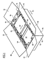
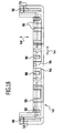
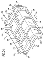
- One in the Fig. 1 to 24 illustrated as a whole with 100 rinsing packaging comprises an outer package 102 in the form of a substantially cuboidal folding carton 104, which comprises a bottom 106, two long side walls 108, two short side walls 110 and at the upper edges of the side walls 108, 110 folding flaps 112 which together form a ceiling wall of the outer packaging 102 in the folded state.
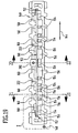
- FIG. 3 to 5 accommodated perspective view from different angles, which two opposing support body 116, a support body 116 interconnecting intermediate element 118 (see Fig. 8 ), a sink 120 disposed between the support bodies 116, a basin cover 122 covering a portion of the top of the sink, a cutting board box 124 resting on the pool cover 122, and a side of the sink 120 remote from the sink 120 between the support bodies 116 and the intermediate element 118 Intermediate element 118 received mixed battery box 126 (see Fig. 5 ).
- each supporting body 116 substantially corresponds to the clear height H of the inner space 114 of the outer packaging 102 in order to prevent vertical movement of the supporting bodies 116 within the outer packaging.
- each support body 116 substantially corresponds to the clear length L of the inner space 114 of the outer package 102 to prevent slippage of the support body 116 within the outer package 102 in the longitudinal direction thereof.
- the packaged sink 120 includes a deep main bowl 128, a shallower auxiliary bowl 130, and a substantially planar, horizontal drainer 132.
- a substantially horizontal sink rim 134 passes around the main bowl 128, the bowl 130 and the drainer 132 and includes two long edge portions 136 which extend parallel to the two long sides of the sink 120 and two short rim portions 138 which extend along the bowl two short sides of the sink 120 extend ( Fig. 7 ).
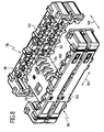
- Each of the two support bodies 116 of the sink package 100 comprises a receiving element 140 and a spacer element 142, wherein the receiving element 140 rests on the upper side of the spacer element 142 and the receiving element 140 and the spacer element 142 have identical shape and orientation.
- the two support bodies 116 of the sink package 100 differ from each other only in that they are rotated by 180 ° about a vertical axis relative to each other.
- the two support bodies 116 of the sink pack 100 thus comprise a total of four elements of identical shape, namely two receiving elements 140 and two spacer elements 142.
- the receiving member 140 is formed as a substantially U-shaped female strip having a central portion 146 extending in the longitudinal direction 144 of the female member 140 and two extending along a transverse direction 148 of the female member 140 which is oriented horizontally and perpendicular to the longitudinal direction 144 End sections 150.
- the receiving element 140 is provided with a receiving channel 152 which is formed by an approximately centrally in the horizontal direction of the sink 120 facing inner sides of the central portion 146 and the end portions 150 extending groove.
- This receiving channel 152 is bounded below by a plurality of support projections 154, which follow one another in the longitudinal direction 144 of the receiving element 140, wherein each two successive support projections 154 by an interposed, extending from the Receiving channel 152 from downwardly extending recess 156 separated from each other and spaced.
- the receiving channel 152 is delimited by a plurality of channel limiting projections 158 which follow one another in the longitudinal direction 144 of the receiving element 140, two channel limiting projections 158 following each other in the longitudinal direction 144 being separated from one another by a respective recess 160 extending upwardly from the receiving channel 152 and are spaced.
- the receiving member 140 When packaging the sink 120, the receiving member 140 is pushed onto the sink rim so that a long edge portion 136 of the sink rim 134 in the central portion of the receiving channel 152 and parts of the short edge portions 138 of the sink rim 134 engage the end portions of the receiving channel 152.
- the sink 120 rests with the underside of the sink edge 143 on the support projections 154 of the receiving element 140.
- the sink 120 is provided on its underside with Garelementhöckern, so it may be provided in particular that the sink 120 is supported on this support member bumps on the support projections 154 of the receiving element 140.
- the receiving element 140 is not pushed onto the rinse edge 134 until the rinse edge 134 rests against the rear side of the receiving channel 152, but only so far until the holding element bumps abut against the respective associated support projections 154.
- the end position of the receiving elements 140 relative to the sink 120 is determined only by the position of the holding element bumps and not by the distance, by which the rinse edge 134 projects beyond the Garelementhöcker to the outside.
- the distance of the two opposing support body 116 of the sink package 100 in this case only on the distance of the opposing Garelementhöcker and not of the total width of the sink (that is, their extension perpendicular to the longitudinal direction of the sink) dependent, whereby it is possible for rinsing 120 different widths to achieve the same width of the sink package 100, so that the same outer package 102 can be used for different widths rinsing.
- the rinse edge 134 is supported only on the support projections 154 and not in the region of the recesses 156 located therebetween on the receiving element 140, so that the rinse edge 134 rests only partially on the receiving element 140.
- the upper side of the rinse edge 134 also comes into contact with the receiving element 140 only in the region of the channel limiting projections 158, but not in the region of the recesses 160 lying therebetween.
- the channel limiting projections 158 on the upper side of the receiving channel 152 lie opposite one of the support projections 154 on the underside of the receiving channel 152.
- the channel limiting projections 158 are arranged offset at the top of the receiving channel 152 relative to the support projections 154 on the underside of the receiving channel 152, that these Kanalbegrenzungsvorsprünge 158 at least partially one of the recesses 156 at the Bottom of the receiving channel 152 are opposite.
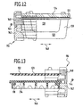
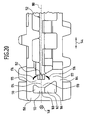
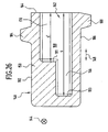
- the end portions 150 of the receiving element 140 are each provided with a cavity 162 which is open only to the end-side end face 164 of the end portion 150.
- the cavity 162 includes a lower portion 166 having a substantially trapezoidal vertical cross-section which widens downwardly toward the inner surface of the end portion 150 toward the sink 120, a central portion 168 substantially contiguous with the lower portion 166 rectangular vertical cross-section and an upper region 170 adjoining the middle region 168 with a substantially trapezoidal vertical cross-section, which widens upwards and towards the inside of the end section 150 facing the sink 120.
- the cross-sectional area of the upper region 170 is significantly smaller than the cross-sectional area of the lower region 166.
- the intermediate central region 168 of the cavity 162 forms a cavity 172 of the cavity formed by the inner wall 174 of the end portion 150 facing the sink 120 projecting into the cavity 162.
- This design of the end portion 150 is achieved that the upper portion 175 of the inner wall 174 and the lower portion 177 of the inner wall 174 upon exertion of pressure on the receiving element 140 slightly to the protruding into the cavity 162 central portion 178 of the inner wall 174 to the through the Central portion 178 extending horizontal plane 180 of the receiving element 140 can be pivoted toward, which has an increased damping effect of the receiving element 140 with respect to acting in the vertical direction on the receiving element 140 impact forces result.
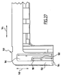
- Fig. 26 and 27 extends the lower portion 166 of the cavity 162 from the end face 164 along the transverse direction 148 by a distance s in the end portion 150 of the receiving member 140 in which is significantly greater than the distance s', around which the upper portion 170 and the central portion 168 of the cavity 162 extend from the end-side end face 164 in the transverse direction 148 into the end portion 150 of the receiving member 140.
- the distance s may in particular be at least 50% greater than the distance s'.
- a step 181 is formed at the rear side of the upper region 170 and the central region 168 of the cavity 162 facing away from the end-side end face 164 of the end section 150 the entire vertical cross-section of the cavity 162 (seen in the direction facing the end-side end face 164) increases abruptly.
- This configuration of the cavity 162 expands the cavity 162 towards the end face 164 of the end portion 150.
- the mechanical stability of the end portion 150 relative to an end portion having a cavity in the transverse direction 148 is constant vertical Cross section increased.
- the vertical cross section of the cavity 162 along the transverse direction 148 is substantially constant.
- the vertical cross-section of the cavity 162 is in the region between the step 181 and the rear side facing away from the end face 164 Boundary surface 183 of the lower portion 166 of the cavity 162 along the transverse direction 148 is substantially constant.
- the receiving element 140 (and thus also the spacer element 142) is provided on its upper side 182 with a plurality of projections 184 extending upwards from the upper side 182.
- the receiving element 140 (and thus also the spacer element 142) is also provided on its underside 186 with a plurality of projections 188 which extend from the bottom 186 downwards.
- the vertical extension of the projections 188 on the underside 186 is substantially the same size as the vertical extent of the projections 184 on the upper side 182, so that when the receiving element 140 is placed on the identically formed spacer element 142, the projections 188 on the underside 186 of the receiving element 140 on the upper side 182 of the spacer element 142 and at the same time abut the projections 184 on the upper side 182 of the spacer element 142 on the underside 186 of the receiving element 140.
- the projections 188 on the bottom 186 and the projections 184 on the top 182 are offset from each other so that when the receiving element 140 is placed on the identically formed spacer element 142, each of the projections 188 on the bottom 186 of Receiving element 140 with one of its inclined against the vertical side surfaces 190 on one of the inclined side surfaces 192 of an adjacently arranged projection 184 on the upper side 182 of the spacer element 142 is flat.
- the projections 184, 188 extend partly transversely to the longitudinal direction 144 and partly transversely to the transverse direction 148 of the receiving element 140, the projections 188 on the underside 186 of the receiving element 140 and the projections 184 on the upper side 182 of the spacer element 142 thus interact with one another in that the receiving element 140 and the spacer element 142 are secured against relative movement both in the longitudinal direction 144 of the receiving element 140 and the spacer element 142 and in the transverse direction 148 of the receiving element 148 and the spacer element 142 and only by a relative movement in the vertical direction from one another can be solved.
- the receiving elements 140 and the spacer elements 142 of the rinse pack 100 are preferably formed as one-piece moldings of a foamed plastic material, in particular of an expanded polystyrene material.
- the sink package 100 further includes the pool cover 122, which rests on top of the sink 120 and covers both the main pool 128 and the auxiliary pool 130 of the sink 120. In this way, a wandering or slipping out of accommodated in the main basin 128 or in the additional basin 130 accessories is prevented.
- the pool cover 122 comprises a substantially rectangular horizontal cover plate 194 and a likewise substantially rectangular vertical support plate 196, which is formed integrally with the horizontal cover plate 194 and along a crease line 198 connects to a Abtrotflansch circuit edge of the horizontal cover plate 194.
- the pool cover 122 is formed of, for example, a cardboard board or a corrugated board.
- the horizontal cover plate 194 is provided at its lateral edges, each with a substantially rectangular recess 200 which is complementary to each one centrally of the sink 120 facing inside of the central portion 146 of a receiving element 146 arranged stop block 202 is formed.
- Each of these stop blocks 202 engages the respective associated recess 200 of the horizontal cover plate 194 and thus secures the pelvic cover 122 against movement relative to the respective receiving element 140 in its longitudinal direction 144 and against movement relative to the two receiving elements 140 in their common transverse direction 148 ,
- a vertical receiving groove 204 is provided in each of the receiving elements 140 on the inside of the central portion 146, in each of which a lateral edge of the vertical holding plate 196 engages.
- the vertical support plate 196 and the receiving grooves 204 of the receiving elements 140 act together so that the pelvic cover 122 is secured against movement relative to the receiving elements 140 in the longitudinal direction 144 and in the transverse direction 148 thereof.
- the vertical support plate 196 and the ceiling wall of the overwrap 102 formed by the flapper pockets 112 cooperate so that the displacement path of the basin cover 122 is limited in the vertical direction.
- the vertical receiving groove 204 preferably extends into one of the projections 184 on the upper side 182 of the receiving element 140, since this increases the vertical extent of the receiving groove 204 and thus the contact surface with the holding plate 196.
- the receiving elements 140 are mirror-symmetrical to their transverse center plane 206, which runs centrally through the stop block 202, the receiving groove 204 for the vertical holding plate 196 of the pelvic cover 122 is present twice on each receiving element 140.
- the horizontal cover plate 194 of the pelvic cover 122 is further provided at its the vertical support plate 196 remote rear free edge with a projection 209 which engages in the space between the end portions 150 of the two receiving elements 140.
- the cutting board box 124 is arranged, which is designed as a substantially cuboid folding box made of cardboard material.
- the width of the cutting board box 124 corresponds to the distance between the inner sides of the central portions 146 of the receiving elements 140, so that the cutting board box 124 is secured by the receiving elements 140 against slipping in the transverse direction 148.
- the cutting board box 124 With its vertical support plate 196 facing front 210, the cutting board box 124 abuts against the stop blocks 202 of the receiving elements 140, so that the displacement of the cutting board box 124 is limited in the direction of the vertical support plate 196 by the stop blocks 202.
- the cutting board box 124 extends to a point 212 (see Fig. 9 ), at which the corner portion of the receiving elements 140 begins and the mutual clear distance of the two opposing receiving elements 140 begins to decrease, so that the displacement of the cutting board box 124 is also limited in the vertical holding plate 196 facing away.
- the cutting board box 124 is thus received substantially free of play between the stop blocks 202 and the corner regions of the receiving elements 140.
- the sink package 100 further includes the in the Fig. 23 and 24 separately shown angular intermediate member 118, which includes a longer horizontal leg 214 and a shorter vertical leg 216.
- the intermediate element 118 is formed integrally and preferably as a shaped body made of a foamable plastic material, in particular of an expanded polystyrene material.
- the material of the additional element 118 substantially coincides with the material of the receiving elements 140 and the spacer elements 142 of the sink package 100.
- the intermediate member 118 is provided on the underside of the horizontal leg 214 and the sink 120 facing away from the front side of the vertical leg 216 with a plurality of recesses 218 and with an opening 219, which cause a weight saving and an improvement in the shock absorption properties of the intermediate element 118th have as a consequence.
- the vertical leg 216 of the intermediate member 118 is provided at its lateral edges with a respective vertically extending projection 220.
- Each of the receiving elements 140 and thus also each of the spacer elements 142 is provided with a vertical receiving groove 222 corresponding to this projection, which is provided on the inner side of the middle section 146 of the respective receiving element 140 or spacer element 142 facing the sink 120 ( Fig. 19 ).
- the vertical projections 220 of the vertical leg 216 of the intermediate member 118 engage in these vertical grooves 222 of the spacer elements 142, so that by the interaction of the vertical projections 220 and the receiving grooves 222, the intermediate member 118 against movement relative to the Spacer elements 142 is secured in the longitudinal direction 144.
- the horizontal leg 214 of the intermediate member 118 is provided on its longitudinal sides and on its side facing away from the vertical leg 216 with a plurality of horizontal projections 224 which engage in the assembled state of the sink package 100 formed between the receiving element 140 and the spacer element 142 of a support body 116 spaces and thus cooperate with the projections 184 on the upper side 182 of the spacer elements 124 and with the projections 188 on the underside 186 of the receiving elements 140 such that the intermediate element 118 prevents movement relative to the two supporting bodies 116 in the longitudinal direction 144, in the transverse direction 148 and secured in the vertical.
- the intermediate member 118 separates the portion of the sink package 100 in which the sink 120 is housed from another portion of the sink package 100 in which the substantially cuboid mixer box 126 is housed.
- the intermediate member 118 fixed relative to the support bodies 116 of the sink package 100 thus prevents the mixer box 126, contained in the relatively heavy accessories, namely the mixer tap of the sink 120, together with tubing and installation material, in the sink package 100 can slip so that it comes into contact with the sink 120 and the same damaged.
- the packaging of the sink 120 by means of the rinse packaging 100 described above can be carried out according to the procedure described below:
- the spacer elements 142 are connected to each other by means of the intermediate member 118 by the vertical projections 220 of the vertical leg 216 of the intermediate member 118 are inserted into the vertical receiving grooves 222 of the spacer elements 142.
- the mixer box 126 is placed in the interior of the outer package 102 and placed on the bottom 106.
- the arrangement of the spacer elements 142 and the intermediate member 118 is inserted into the interior of the outer package 102 that the spacer elements 142 sit parallel to the long side walls 108 of the outer package 102 aligned longitudinal directions 144 on the bottom 106 of the outer package 102 and the mixer box 126th is fixed by the intermediate element 118 in the desired packaging position within the outer package 102.
- the receiving elements 140 of the support body 116 are laterally pushed onto the edge portions 136, 138 of the sink rim 134 of the sink 120, so that the sink edge 134 engages in the receiving channels 152 of the receiving elements 140.
- the pelvic cover 122 After attaching the receiving elements 140, the pelvic cover 122 is placed on top of the sink 120 by first pushing the rear free edge of the horizontal cover plate 194 of the pelvic cover 122 under the protrusions 208 on the end portions 150 of the receptacles 140, the pelvis cover 122 thus inclined to the horizontal, that the vertical support plate 196 is above the receiving elements 140, and then the pelvic cover 122 is pivoted about the rear free edge of the horizontal cover plate 194 down that the vertical support plate 196 of the pelvic cover 122 in the hereby corresponding Receiving grooves 204 of the receiving elements 140 engages until the pelvic cover 122 rests on the top of the sink 120 and the main basin 128 and the additional basin 130 covered.
- the arrangement of the sink 120, the receiving elements 140 and the basin cover 122 is introduced vertically from above into the interior 114 of the outer packaging 102 and with the lower sides 186 of the receiving elements 140 on the upper sides 182 of the spacer elements 142 deposed.
- the cutting board box 124 is placed on the pelvic cover 122 so that it rests against the stop blocks 202 of the receiving elements 140.
- folding pockets 112 of the outer packaging 102 are folded in order to form a closed ceiling wall of the outer packaging 102, which is permanently closed and ready for transport, for example by means of adhesive strips or strapping made of a band-shaped material.
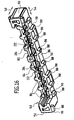
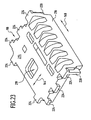
- the same receiving elements 140 of the supporting bodies 116 of the rinsing pack 100 described above can be stacked directly on one another, the same receiving elements 140 can also be used to produce a stack 224 of rinses 120, as in FIG Fig. 25 is shown.
- two receiving elements 140 which are formed exactly like the receiving elements 140 described above, are pushed onto mutually opposite edge sections of the rinsing edge 134 of the respective sink 120, so that the edge sections 136, 138 of the rinsing edge 134 in FIG the receiving channels 152 of the receiving elements 140 engage.
- the receiving elements 140 are fixed to the sink 120, for example by means of adhesive strips and / or by means of a strapping of a strip material.
- a plurality of rinses 120 with the receiving elements 140 arranged thereon are stacked on one another by the receiving elements 140 connected to a sink 120a each being placed vertically from above onto the receiving elements 140 of a sink 120b arranged thereunder until the receiving elements 140 of the upper sink 120a with its lower side 186 rest on the upper side 182 of the receiving elements 140 of the lower sink 120b, as shown in FIG Fig. 25 is shown.
- the main basin 128 and the additional basin 130 of the upper sink 120a submerge in the main basin 128 or in the additional basin 130 of the lower sink 120b, so that the stack height per sink, that is, the vertical spacing of the sink rims 134 in the stack 224, is lower is greater than the height of a sink 120.
- the sinks 120 can be arranged in a particularly space-saving manner in the form of the stack 224 and stored in this arrangement, for example, before a single transport in an outer package 102.
- the rinsings 120 stored in the stack 224 can be packaged individually in an outer packaging 102 without prior removal of the receiving elements 140 and thus particularly time-saving be reduced, and also the number of required for the storage in the stack 224 and for the subsequent individual packaging of the sinks 120 in each case a rinse packaging 100 packaging elements.
Abstract
Description
Die vorliegende Erfindung betrifft eine Verpackung für eine Spüle gemäß dem Oberbegriff des Anspruchs 1.The present invention relates to a package for a sink according to the preamble of claim 1.
Es ist bekannt, Spülen jeweils einzeln in einem Transportkarton zu verpacken, wobei Formkörper aus einem geschäumten Kunststoffmaterial dazu benutzt werden, die Spüle gegen die Einwirkung von Stoßbeanspruchungen zu schützen.It is known to package rinses one at a time in a shipping carton, wherein molded articles of a foamed plastic material are used to protect the sink against the effects of shock loads.
Insbesondere ist eine Verpackung für eine Spüle bekannt, bei welcher zwei Aufnahmeleisten aus geschäumtem Material auf die kurzen Längsseiten des Randes einer Spüle, welche zwei gleich große Spülbecken umfasst, aufgeschoben werden. Bei dieser Spülenverpackung wird ferner ein im Querschnitt U-förmiger Stegschutz von oben auf den zwischen den beiden Becken angeordneten Zwischensteg gesteckt, und die beiden Becken werden nach unten durch einen im wesentlichen T-förmigen Stützkörper abgestützt, welcher unter den Beckenböden und unter dem die beiden Becken voneinander trennenden Zwischensteg angeordnet ist. Diese bekannte Spülenverpackung umfasst somit vier Formkörper aus geschäumtem Kunststoffmaterial, welche separat voneinander an der Spüle angeordnet sind und nicht in Kontakt miteinander stehen.In particular, a package for a sink is known, in which two receiving strips of foamed material on the short longitudinal sides of the edge of a sink, which comprises two equal size sinks, are postponed. In this Spülenverpackung also a cross-sectionally U-shaped bar protection is placed from above on the arranged between the two basins gutter, and the two basins are supported downwards by a substantially T-shaped support body, which under the pool floors and under the two Basin separating divider is arranged. This known rinse packaging thus comprises four molded bodies made of foamed plastic material, which are arranged separately from one another on the sink and are not in contact with each other.
Die
Der vorliegenden Erfindung liegt die Aufgabe zugrunde, eine Verpackung für eine Spüle zu schaffen, welche besonders gute Dämpfungseigenschaften und eine geringe Transportschadenquote aufweist.The present invention has for its object to provide a package for a sink, which has particularly good damping properties and low transport damage rate.
Diese Aufgabe wird erfindungsgemäß durch eine Verpackung für eine Spüle gelöst, die mindestens einen Stützkörper umfasst, der seinerseits mindestens ein Aufnahmeelement mit einem Aufnahmekanal für einen Randabschnitt der Spüle und mindestens ein separat von dem Aufnahmeelement ausgebildetes Distanzhalterelement, welches das Aufnahmeelement abstützt, umfaßt, wobei das Aufnahmeelement und/oder das Distanzhalterelement zumindest teilweise aus einem geschäumten Kunststoffmaterial gebildet ist.This object is achieved by a package for a sink, comprising at least one support body, in turn, at least one receiving element with a receiving channel for an edge portion of the sink and at least one separately formed by the receiving element spacer element which supports the receiving element, wherein the Receiving element and / or the spacer element is at least partially formed of a foamed plastic material.
Dadurch, daß bei der erfindungsgemäßen Spülenverpackung das den Randabschnitt der Spüle aufnehmende Aufnahmeelement mit dem das Aufnahmeelement abstützenden Distanzhalterelement unmittelbar in Kontakt steht, wird eine besonders hohe Dämpfungswirkung gegenüber von außen auf die Spülenverpackung einwirkenden Stößen erzielt. Da der Stützkörper der erfindungsgemäßen Spülenverpackung nicht einstückig ausgebildet ist, sondern zwei separate Elemente umfaßt, die an mindestens einer Kontaktfläche miteinander in Kontakt stehen, wird erreicht, daß Stoßbeanspruchungen sich nicht ungestört durch den gesamten Stützkörper hindurch ausbreiten können, wie dies bei einem einstückigen Stützkörper der Fall ist, sondern vielmehr durch den Übergang von dem einen Element zu dem anderen Element des Stützkörpers an der Kontaktfläche eine zusätzliche Dämpfung von Stößen erfolgt.Due to the fact that, in the case of the rinsing packaging according to the invention, the receiving element receiving the edge section of the sink is in direct contact with the spacer element supporting the receiving element, a particularly high damping effect is achieved against impacts acting on the rinse packaging from the outside. Since the support body of the sink package according to the invention is not integrally formed, but comprises two separate elements which are in contact with each other at least one contact surface, it is achieved that impact stresses can not spread undisturbed through the entire support body, as in a one-piece support body of Case is, but rather takes place by the transition from the one element to the other element of the support body at the contact surface an additional damping of shocks.
Zugleich wird aber die Dämpfungskapazität des Stützkörpers aufgrund des zusätzlichen Volumens des Distanzhalterelements gegenüber einem Stützkörper, welcher nur das Aufnahmeelement umfassen würde, erhöht.At the same time, however, the damping capacity of the support body due to the additional volume of the spacer element relative to a support body, which would include only the receiving element, increased.
Das Distanzhalterelement kann insbesondere auf dem Boden einer Umverpackung der Spülenverpackung aufsitzen.The spacer element can sit in particular on the bottom of an outer packaging of the sink package.
Dadurch, daß das Aufnahmeelement und/oder das Distanzhalterelement des Stützkörpers zumindest teilweise, vorzugsweise vollständig, aus einem geschäumten Kunststoffmaterial gebildet sind, wird eine weitaus bessere Dämpfungswirkung erzielt als beispielsweise bei der Verwendung von Verpackungselementen aus Wellpappe.The fact that the receiving element and / or the spacer element of the support body are at least partially, preferably completely, formed of a foamed plastic material, a much better Damping effect achieved, for example, when using packaging elements made of corrugated cardboard.
Aufgrund der guten Dämpfungseigenschaften und der daraus resultierenden geringen Transportschadensquote ist die erfindungsgemäße Spülenverpackung insbesondere für die Verpackung von besonders bruchempfindlichen Spülen, beispielsweise aus Keramik und/oder Verbundwerkstoffen, geeignet.Due to the good damping properties and the resulting low transport damage rate, the rinse packaging according to the invention is particularly suitable for the packaging of particularly fragile rinses, for example of ceramic and / or composite materials.
Die erfindungsgemäße Spülenverpackung erlaubt es, Spülen besonders kostengünstig und prozeßsicher zu verpacken.The rinsing packaging according to the invention makes it possible to package rinses in a particularly cost-effective and process-reliable manner.
Eine besonders gute Stabilität der Verpackung und Dämpfungswirkung derselben wird erzielt, wenn vorteilhafterweise vorgesehen ist, daß der Aufnahmekanal des Aufnahmeelements zur Aufnahme eines Randabschnitts an einer langen Seite der Spüle ausgebildet ist.A particularly good stability of the packaging and damping effect of the same is achieved if it is advantageously provided that the receiving channel of the receiving element is designed to receive an edge portion on a long side of the sink.
Als besonders günstig hat es sich erwiesen, wenn der Aufnahmekanal des Aufnahmeelements zur Aufnahme eines Randabschnitts der Spüle ausgebildet ist, der sich über die gesamte Länge einer Seite der Spüle, vorzugsweise einer langen Seite der Spüle, erstreckt.It has proved to be particularly favorable when the receiving channel of the receiving element is designed to receive an edge portion of the sink, which extends over the entire length of one side of the sink, preferably a long side of the sink.
Der Randabschnitt der Spüle wird besonders gut durch die Spülenverpackung geschützt, wenn der Aufnahmekanal des Aufnahmeelements zur Aufnahme eines Randabschnitts der Spüle, der sich längs einer ersten Seite der Spüle, und zur Aufnahme eines Randabschnitts der Spüle, der sich längs einer zweiten Seite der Spüle erstreckt, ausgebildet ist.The edge portion of the sink is particularly well protected by the rinse wrap when the receiving channel of the receiving member for receiving a rim portion of the sink, which extends along a first side of the sink, and for receiving a rim portion of the sink, which extends along a second side of the sink , is trained.
Besonders günstig ist es, wenn der Aufnahmekanal des Aufnahmeelements ferner zur Aufnahme eines Randabschnitts der Spüle ausgebildet ist, der sich längs einer dritten Seite der Spüle erstreckt.It is particularly advantageous if the receiving channel of the receiving element is further designed to receive an edge portion of the sink, which extends along a third side of the sink.
Da die Eckbereiche der Spüle in besonders hohem Maße Stößen beim Transport ausgesetzt sind, ist es von Vorteil, wenn der Aufnahmekanal des Aufnahmeelements zur Aufnahme mindestens eines Eckbereichs des Randes der Spüle ausgebildet ist.Since the corner regions of the sink are exposed to a particularly high degree of impact during transport, it is advantageous if the receiving channel of the receiving element is designed to receive at least one corner region of the edge of the sink.
Um die Anzahl der für die Spülenverpackung benötigten, unterschiedlichen Element möglichst gering zu halten, ist es von Vorteil, wenn das Distanzhalterelement des Stützkörpers dieselbe Gestalt aufweist wie das Aufnahmeelement des Stützkörpers.In order to keep the number of required for the sink packaging, different element as small as possible, it is advantageous if the spacer element of the support body has the same shape as the receiving element of the support body.
Bei einer bevorzugten Gestaltung der Erfindung ist vorgesehen, daß die Verpackung mindestens zwei Stützkörper umfaßt, die jeweils mindestens ein Aufnahmeelement mit einem Aufnahmekanal für einen Randabschnitt der Spüle und mindestens ein separat von dem Aufnahmeelement ausgebildetes Distanzhalterelement, welches das jeweils zugeordnete Aufnahmeelement abstützt, umfassen.In a preferred embodiment of the invention it is provided that the packaging comprises at least two support bodies, each comprising at least one receiving element with a receiving channel for an edge portion of the sink and at least one separately formed from the receiving element spacer element, which supports the respective associated receiving element.
In diesem Fall ist es zur Reduktion der Anzahl der für die Verpackung benötigten unterschiedlichen Elemente von Vorteil, wenn die Aufnahmeelemente und die Distanzhalterelemente der mindestens zwei Stützkörper dieselbe Gestalt aufweisen.In this case, it is advantageous for reducing the number of different elements required for the packaging when the receiving elements and the spacer elements of the at least two supporting bodies have the same shape.
Bei einer besonders bevorzugten Ausgestaltung der Spülenverpackung umfaßt dieselbe zwei Stützkörper, welche insgesamt zwei Aufnahmeelemente und zwei Distanzhalterelemente umfassen, wobei alle vier dieser Elemente dieselbe Gestalt aufweisen, so daß alle diese Elemente innerhalb der Verpackung untereinander ausgetauscht werden können und nur ein Werkzeug zur Herstellung all dieser Elemente erforderlich ist.In a particularly preferred embodiment of the sink package, the same comprises two support bodies which comprise a total of two receiving elements and two spacer elements, all four of these elements being the same Have shape, so that all these elements can be interchanged within the package and only a tool for producing all these elements is required.
Vorzugsweise sind die mindestens zwei Stützkörper der Verpackung an einander gegenüberliegenden Randabschnitten der Spüle angeordnet.Preferably, the at least two support bodies of the packaging are arranged on opposite edge portions of the sink.
Als besonders günstig für das Dämpfungsverhalten der Verpackung hat es sich erwiesen, wenn das gesamte Gewicht der Spüle ausschließlich von den Stützkörpern, welche jeweils ein Aufnahmeelement mit einem Aufnahmekanal für einen Randabschnitt der Spüle umfassen, getragen wird. Diese Ausbildung der Erfindung hat den weiteren Vorteil, daß kein weiterer Bestandteil der Spülenverpackung zwingend erforderlich ist, was die Anzahl der für die Verpackung der Spüle benötigten Elemente reduziert.It has proved to be particularly favorable for the damping behavior of the package when the entire weight of the sink is carried exclusively by the support bodies, which each comprise a receiving element with a receiving channel for a rim portion of the sink. This embodiment of the invention has the further advantage that no further component of the sink packaging is absolutely necessary, which reduces the number of elements required for the packaging of the sink.
Vorzugsweise sitzt das mindestens eine Becken der Spüle auf keinem Element der Verpackung auf.Preferably, the at least one basin of the sink sits on no element of the package.
Bei einer bevorzugten Ausgestaltung der Erfindung umfaßt die Verpackung ferner eine Umverpackung, deren Innenraum die Spüle und den mindestens einen Stützkörper aufnimmt.In a preferred embodiment of the invention, the packaging further comprises an outer packaging whose interior receives the sink and the at least one support body.
Diese Umverpackung kann insbesondere im wesentlichen quaderförmig ausgebildet sein.This outer packaging may be formed in particular substantially cuboid.
Ferner kann vorgesehen sein, daß die Umverpackung einen Faltkarton umfaßt.Furthermore, it can be provided that the outer packaging comprises a folding carton.
Besonders günstig ist es, wenn sich der mindestens eine Stützkörper über im wesentlichen die gesamte lichte Höhe des Innenraums der Umverpackung erstreckt. Auf diese Weise wird der Verschiebungsweg der die Spüle tragenden Stützkörper beim Transport der Verpackung in der vertikalen Richtung verringert und vermieden, daß die Spüle gegen die Umverpackung stößt.It is particularly favorable if the at least one support body extends over substantially the entire clear height of the interior of the outer packaging extends. In this way, the displacement path of the support body supporting the sink is reduced in the vertical direction during transport of the package and prevents the sink abuts against the outer packaging.
Im Rahmen dieser Beschreibung und der beigefügten Ansprüche ist unter einem Stützkörper, der sich über im wesentlichen die gesamte lichte Höhe des Innenraums der Umverpackung erstreckt, ein Stützkörper zu verstehen, dessen Höhe (vertikale Erstreckung) mindestens 90 Prozent der lichten Höhe H des Innenraums beträgt.In the context of this description and the appended claims, a support body which extends over substantially the entire clear height of the interior of the outer packaging, a support body to understand the height (vertical extent) is at least 90 percent of the clear height H of the interior.
Besonders günstig ist es, wenn die Höhe des Stützkörpers mindestens 95 Prozent der gesamten lichten Höhe des Innenraums der Umverpackung beträgt.It is particularly favorable if the height of the support body is at least 95 percent of the total clear height of the interior of the outer packaging.
Das Aufnahmeelement der erfindungsgemäßen Spülenverpackung kann insbesondere als eine Aufnahmeleiste ausgebildet sein.The receiving element of the rinsing packaging according to the invention can be designed in particular as a receiving strip.
Wenn das Aufnahmeelement im wesentlichen L-förmig ausgebildet ist, so ist nur die Lage eines Eckbereichs des Spülenrandes relativ zu dem Aufnahmeelement festgelegt, während die freien Enden der Schenkel des L-förmigen Aufnahmeelements von den anderen Eckbereichen des Randes der Spüle um grundsätzlich beliebige Strecken beabstandet sein können. Ein solches Aufnahmeelement kann somit zur Verpackung beliebig breiter und beliebig langer Spülen verwendet werden.If the receiving element is formed substantially L-shaped, so only the position of a corner region of the sink edge is set relative to the receiving element, while the free ends of the legs of the L-shaped receiving element from the other corner regions of the edge of the sink to basically any distances could be. Such a receiving element can thus be used for packaging arbitrarily wide and arbitrarily long rinsing.
Alternativ hierzu kann auch vorgesehen sein, daß das Aufnahmeelement im wesentlichen U-förmig ausgebildet ist. Bei dieser Ausführungsform ist die Lage des Aufnahmeelements bezüglich zweier Eckbereiche des Spülenrandes festgelegt. Der Abstand der freien Enden des U-förmigen Aufnahmeelements von den beiden weiteren Eckbereichen des Spülenrandes ist jedoch grundsätzlich beliebig, so daß ein solches U-förmiges Aufnahmeelement für die Verpackung von Spülen mit einer innerhalb eines Toleranzintervalls vorgegebenen Länge, jedoch unterschiedlicher Breite verwendet werden kann. Das Toleranzintervall wird dabei durch die Tiefe des Aufnahmekanals in den Endbereichen des U-förmigen Aufnahmeelements, d. h. durch dessen Erstreckung in der Querrichtung des Aufnahmeelements, bestimmt und erlaubt es, Spülen mit innerhalb des Toleranzintervalls variierenden Längen mittels derselben Aufnahmeelemente zu verpacken, wobei diese Aufnahmeelemente mit ihren Mittelbereichen auf die langen Seiten der Spülen aufgeschoben werden.Alternatively, it can also be provided that the receiving element is formed substantially U-shaped. In this embodiment, the position of the receiving element with respect to two corner regions of the rinse edge is fixed. However, the distance between the free ends of the U-shaped receiving element of the other two corner regions of the sink edge is basically arbitrary, so that such a U-shaped receiving element for the packaging of sinks with a predetermined within a tolerance interval length, but different width can be used. The tolerance interval is determined by the depth of the receiving channel in the end regions of the U-shaped receiving element, ie by its extension in the transverse direction of the receiving element, and allows rinsing with varying within the tolerance interval lengths to pack by means of the same receiving elements, said receiving elements with their mid-sections are pushed onto the long sides of the sinks.
Ferner kann ein solches U-förmiges Aufnahmeelement für die Verpackung von Spülen mit einer innerhalb eines Toleranzintervalls vorgegebenen Breite, jedoch unterschiedlicher Länge verwendet werden. Das Toleranzintervall wird dabei durch die Tiefe des Aufnahmekanals in den Endbereichen des U-förmigen Aufnahmeelements, d. h. durch dessen Erstreckung in der Querrichtung des Aufnahmeelements, bestimmt und erlaubt es, Spülen mit innerhalb des Toleranzintervalls variierenden Breiten mittels derselben Aufnahmeelemente zu verpacken, wobei diese Aufnahmeelemente mit ihren Mittelbereichen auf die kurzen Seiten der Spülen aufgeschoben werden.Furthermore, such a U-shaped receiving element for the packaging of rinses with a predetermined within a tolerance interval width, but different lengths are used. The tolerance interval is determined by the depth of the receiving channel in the end regions of the U-shaped receiving element, d. H. by its extension in the transverse direction of the receiving element, determines and allows to pack rinses with varying widths within the tolerance interval by means of the same receiving elements, these receiving elements are pushed with their central regions on the short sides of the sinks.
Bei einer bevorzugten Ausgestaltung der Erfindung ist vorgesehen, daß das Aufnahmeelement einen Längsabschnitt umfaßt, der sich in der Längsrichtung der Spüle erstreckt.In a preferred embodiment of the invention it is provided that the receiving element comprises a longitudinal portion which extends in the longitudinal direction of the sink.
Ferner kann vorgesehen sein, daß das Aufnahmeelement mindestens einen Querabschnitt umfaßt, der sich in der Querrichtung der Spüle erstreckt.Furthermore, it can be provided that the receiving element comprises at least one transverse section which extends in the transverse direction of the sink.
Vorzugsweise endet der Querabschnitt dabei im Abstand von der Längsmittelebene der Spüle, so daß vermieden wird, daß die freien Enden der Aufnahmeelemente einander gegenüberliegender Stützkörper in Kontakt miteinander gelangen.Preferably, the transverse section ends at a distance from the longitudinal center plane of the sink, so that it is avoided that the free ends of the receiving elements of opposing support body come into contact with each other.
Besonders gute Dämpfungseigenschaften des Aufnahmeelements werden erzielt, wenn der Aufnahmekanal des Aufnahmeelements nach oben und/oder nach unten durch mehrere Kanalbegrenzungsvorsprünge begrenzt ist, die in der Längsrichtung des Aufnahmekanals voneinander beabstandet sind, so daß die Spüle nur an den Kanalbegrenzungsvorsprüngen, nicht aber in den zwischen den Kanalbegrenzungsvorsprüngen liegenden Bereichen mit dem Aufnahmeelement in Kontakt kommt.Particularly good damping properties of the receiving element are achieved when the receiving channel of the receiving element is bounded above and / or down by a plurality Kanalbegrenzungsvorsprünge, which are spaced apart in the longitudinal direction of the receiving channel, so that the sink only at the Kanalbegrenzungsvorsprüngen, but not in the between the channel limiting projections lying areas comes into contact with the receiving element.
Ferner ist vorzugsweise vorgesehen, daß das Aufnahmeelement mindestens einen Endabschnitt umfaßt, der mit mindestens einem Hohlraum versehen ist.Further, it is preferably provided that the receiving element comprises at least one end portion which is provided with at least one cavity.
Eine besonders gute elastische Verformbarkeit und damit eine besonders gute Dämpfungswirkung des Endabschnitts des Aufnahmeelements wird dabei erzielt, wenn der Hohlraum einen vertikalen Querschnitt aufweist, der eine Einschnürung aufweist.A particularly good elastic deformability and thus a particularly good damping effect of the end portion of the receiving element is achieved when the cavity has a vertical cross section having a constriction.
Ein Endabschnitt des Aufnahmeelements mit guter Dämpfungswirkung und dennoch hoher Stabilität wird erhalten, wenn der in dem Endabschnitt ausgebildete Hohlraum sich zu einer Stirnseite des Endabschnitts hin erweitert.An end portion of the receiving member with good damping effect and yet high stability is obtained when the cavity formed in the end portion widens toward an end face of the end portion.
Der Hohlraum hat in diesem Fall einen in der Längsrichtung des Endabschnitts variierenden vertikalen Querschnitt.The cavity in this case has a vertical cross section varying in the longitudinal direction of the end portion.
Dabei kann die Variation des vertikalen Querschnitts kontinuierlich oder aber auch in einem oder mehreren diskreten Schritten erfolgen.In this case, the variation of the vertical cross section can take place continuously or else in one or more discrete steps.
Als besonders günstig hat es sich erwiesen, wenn der Hohlraum an der Stirnseite des Endabschnitts mündet.It has proved to be particularly favorable when the cavity opens at the end face of the end section.
Ferner hat es sich als günstig erwiesen, wenn der mit dem Hohlraum versehene Endabschnitt an seiner der Spüle zugewandten Seite mit einer Ausnehmung (beispielsweise dem Aufnahmekanal) versehen ist, wodurch die Verformbarkeit des Endabschnitts unter Einwirkung einer Stoßbelastung erhöht wird.Furthermore, it has proved to be advantageous if the end portion provided with the cavity is provided on its side facing the sink with a recess (for example, the receiving channel), whereby the deformability of the end portion is increased under the action of a shock load.
Das Aufnahmeelement kann an seiner Oberseite mit Vorsprüngen versehen sein, welche an einer Deckenwand der Umverpackung der Spülenverpackung zur Anlage kommen, so daß Stöße von der Umverpackung auf das Aufnahmeelement nicht über die gesamte Oberseite des Aufnahmeelements, sondern nur über die in der Längsrichtung des Aufnahmeelements voneinander beabstandeten Vorsprünge auf das Aufnahmeelement übertragen werden können.The receiving element may be provided on its upper side with projections which come to rest on a top wall of the outer packaging of the sink package, so that impacts from the outer packaging on the receiving element not over the entire top of the receiving element, but only on the one another in the longitudinal direction of the receiving element spaced projections can be transferred to the receiving element.
Ebenso kann vorgesehen sein, daß das Distanzhalterelement an seiner Unterseite mit Vorsprüngen versehen ist, die an einer Bodenwand der Umverpackung der Spülenverpackung zur Anlage kommen, so daß Stöße von der Bodenwand der Umverpackung nicht über die gesamte Unterseite des Distanzhalterelements, sondern nur über die in der Längsrichtung des Distanzhalterelements voneinander beabstandeten Vorsprünge auf das Distanzhalterelement übertragen werden können.Likewise, it can be provided that the spacer element is provided on its underside with projections which come to rest on a bottom wall of the outer packaging of the sink package, so that shocks from the bottom wall of the outer packaging not over the entire bottom of the spacer element, but only on in the Longitudinal direction of the spacer element spaced apart projections can be transferred to the spacer element.
Bei einer bevorzugten Ausgestaltung der Erfindung ist das Aufnahmeelement an seiner Unterseite mit Vorsprüngen und/oder mit Ausnehmungen versehen und das Distanzhalterelement an seiner Oberseite mit Vorsprüngen und/oder mit Ausnehmungen versehen und wirken die Vorsprünge und/oder die Ausnehmungen an der Unterseite des Aufnahmeelements so mit den Vorsprüngen und/oder den Ausnehmungen an der Oberseite des Distanzhalterelements zusammen, daß das auf das Distanzhalterelement aufgesetzte Aufnahmeelement in seiner Längsrichtung und/oder in einer quer zu seiner Längsrichtung verlaufenden horizontalen Querrichtung relativ zu dem Distanzhalterelement fixiert ist. Diese Ausgestaltung trägt zu einer erhöhten Stabilität des Stützkörpers, der aus dem Aufnahmeelement und dem Distanzhalterelement gebildet ist, bei, da in diesem Fall das Aufnahmeelement und das Distanzhalterelement nur durch eine vertikal verlaufende Relativbewegung voneinander gelöst werden können.In a preferred embodiment of the invention, the receiving element is provided on its underside with projections and / or with recesses and the spacer element provided on its upper side with projections and / or recesses and the protrusions and / or the recesses on the underside of the receiving element so cooperate with the projections and / or the recesses on the upper side of the spacer element that the patch on the spacer element Receiving element is fixed in its longitudinal direction and / or in a direction transverse to its longitudinal direction horizontal transverse direction relative to the spacer element. This embodiment contributes to an increased stability of the support body, which is formed from the receiving element and the spacer element, at, since in this case the receiving element and the spacer element can only be solved by a vertically extending relative movement of each other.
Bei einer bevorzugten Ausgestaltung der erfindungsgemäßen Verpackung umfaßt dieselbe ein Abdeckelement, das zumindest einen Teil der Spüle nach oben hin abdeckt.In a preferred embodiment of the packaging according to the invention, the same comprises a covering element which covers at least part of the sink upwards.
Insbesondere kann vorgesehen sein, daß das Abdeckelement mindestens ein Becken der Spüle nach oben hin abdeckt. Auf diese Weise wird ein Wandern oder Herausrutschen von in diesem Becken der Spüle untergebrachtem Zubehör verhindert.In particular, it can be provided that the cover at least covers a basin of the sink upwards. In this way, a walk or slipping out of this sink of the sink accommodated accessories is prevented.
Vorzugsweise erstreckt sich das Abdeckelement nicht über die gesamte Oberseite der Spüle.Preferably, the cover does not extend over the entire top of the sink.
Als günstig hat es sich erwiesen, wenn das Abdeckelement so mit dem Aufnahmeelement in Eingriff steht, daß es gegen eine Verschiebung relativ zu dem Aufnahmeelement in dessen Längsrichtung gesichert ist.As low it has been found when the cover is so engaged with the receiving element, that it is secured against displacement relative to the receiving element in the longitudinal direction.
Insbesondere kann ferner vorgesehen sein, daß das Abdeckelement so mit dem Aufnahmeelement in Eingriff steht, daß sein Verschiebungsweg relativ zu dem Aufnahmeelement in vertikaler Richtung beschränkt ist, vorzugsweise auf höchstens ungefähr 3 cm.In particular, it may further be provided that the cover is so engaged with the receiving element that its displacement path is limited relative to the receiving element in the vertical direction, preferably at most about 3 cm.
Das Abdeckelement kann einen im wesentlichen horizontalen Abdeckabschnitt und einen quer, vorzugsweise im wesentlichen senkrecht, zu dem Abdeckabschnitt ausgerichteten Halteabschnitt umfassen.The cover member may comprise a substantially horizontal cover portion and a transverse, preferably substantially perpendicular, aligned to the cover portion holding portion.
Die erfindungsgemäße Verpackung kann ferner mindestens eine Zubehörkiste, beispielsweise eine Schneidbrettkiste umfassen, wobei es günstig ist, wenn das Aufnahmeelement mindestens einen Anschlag aufweist, der den Verschiebeweg der Zubehörkiste relativ zu dem Aufnahmeelement in der Längsrichtung des Aufnahmeelements begrenzt. Hierdurch wird ein Verrutschen der Zubehörkiste beim Transport in der Längsrichtung des Aufnahmeelements verhindert.The packaging according to the invention may further comprise at least one accessory box, for example a cutting board box, it being favorable if the receiving element has at least one stop limiting the displacement path of the accessory box relative to the receiving element in the longitudinal direction of the receiving element. This prevents slippage of the accessory box during transport in the longitudinal direction of the receiving element.
Wenn die Verpackung zwei Stützkörper mit mindestens einem Aufnahmeelement und ferner eine Zubehörkiste umfaßt, so entspricht vorzugsweise der horizontale Abstand der Aufnahmeelemente voneinander im wesentlichen der Breite der Zubehörkiste, so daß die Zubehörkiste mit nur geringem Spiel zwischen den Aufnahmeelementen aufgenommen und gegen ein Verrutschen in der Querrichtung der Aufnahmeelemente gesichert ist.If the package comprises two supporting bodies with at least one receiving element and also an accessory box, then preferably the horizontal spacing of the receiving elements from each other substantially equal to the width of the accessory box, so that the accessory box with little clearance between the receiving elements and against slipping in the transverse direction the receiving elements is secured.
Bei einer bevorzugten Ausgestaltung der Erfindung umfaßt die Verpackung mindestens zwei Stützkörper mit jeweils einem Aufnahmeelement und ferner ein zwischen den beiden Stützkörpern angeordnetes Zwischenelement.In a preferred embodiment of the invention, the packaging comprises at least two support bodies each having a receiving element and further comprises an intermediate element arranged between the two support bodies.
Das Zwischenelement steht vorzugsweise so mit den Stützkörpern in Eingriff, daß es gegen eine Bewegung relativ zu den Stützkörpern in deren Längsrichtung gesichert ist.The intermediate member is preferably engaged with the support bodies so as to be secured against movement relative to the support bodies in the longitudinal direction thereof.
Ferner ist es günstig, wenn das Zwischenelement so mit den Stützkörpern in Eingriff steht, daß es gegen eine vertikale Bewegung relativ zu den Stützkörpern gesichert ist.Further, it is advantageous if the intermediate element is so engaged with the support bodies that it is secured against vertical movement relative to the support bodies.
Dieses Zwischenelement kann mindestens einen Vorsprung aufweisen, der in einen Zwischenraum zwischen dem Aufnahmeelement und dem Distanzhalterelement eines der Stützkörper eingreift.This intermediate element may have at least one projection which engages in a gap between the receiving element and the spacer element of one of the support body.
Das Zwischenelement kann im wesentlichen winkelförmig ausgebildet sein und insbesondere einen im wesentlichen horizontalen ersten Abschnitt und einen quer, vorzugsweise im wesentlichen senkrecht, zu dem horizontalen ersten Abschnitt ausgerichteten zweiten Abschnitt umfassen.The intermediate element may be formed substantially angularly and in particular comprise a substantially horizontal first portion and a transversely, preferably substantially perpendicular, aligned to the horizontal first portion second portion.
Ferner kann vorgesehen sein, daß die Verpackung eine unterhalb der Spüle angeordnete Zubehöreinheit umfaßt, wobei das Zwischenelement so ausgebildet und angeordnet ist, daß es die Zubehöreinheit, beispielsweise eine Mischbatteriekiste, von der Spüle trennt.It may further be provided that the package comprises an accessory unit disposed below the sink, wherein the intermediate member is formed and arranged to separate the accessory unit, for example a mixer box, from the sink.
Auf diese Weise wird verhindert, daß während des Transports die Zubehöreinheit mit der Spüle in Kontakt kommt, wobei sowohl die Zubehöreinheit als auch die Spüle beschädigt werden könnten.In this way it is prevented that the accessory unit comes into contact with the sink during transport, whereby both the accessory unit and the sink could be damaged.
Um Gewicht einzusparen und die Dämpfungseigenschaften des Zwischenelements zu verbessern, kann vorgesehen sein, daß das Zwischenelement auf seiner der Spüle abgewandten Seite mit mindestens einer Ausnehmung versehen ist.In order to save weight and to improve the damping properties of the intermediate element, it can be provided that the intermediate element on his side facing away from the sink is provided with at least one recess.
Vorzugsweise ist das Zwischenelement aus im wesentlichen demselben Material gebildet wie die Aufnahmeelemente der Stützkörper.Preferably, the intermediate element is formed from substantially the same material as the receiving elements of the support body.
Das Aufnahmeelement und/oder das Distanzhalterelement können insbesondere zumindest teilweise aus einem expandierten Polystyrol-Material gebildet sein.The receiving element and / or the spacer element may in particular be formed at least partially from an expanded polystyrene material.
Das Aufnahmeelement kann in gleicher Weise auf beiden Seiten der Spüle angeordnet werden, wenn vorteilhafterweise vorgesehen ist, daß das Aufnahmeelement im wesentlichen symmetrisch zu seiner vertikalen Quermittelebene ausgebildet ist.The receiving element can be arranged in the same way on both sides of the sink, if it is advantageously provided that the receiving element is formed substantially symmetrically to its vertical transverse center plane.
Bei einer bevorzugten Ausgestaltung der Erfindung ist ferner vorgesehen, daß das Aufnahmeelement direkt auf ein anderes Aufnahmeelement gleicher Gestalt und Orientierung stapelbar ist.In a preferred embodiment of the invention it is further provided that the receiving element is stackable directly on another receiving element of the same shape and orientation.
Das Aufnahmeelement läßt sich außer zur Einzelverpackung der Spüle auch zur Stapelverpackung mehrerer Spülen verwenden, wenn das Aufnahmeelement, in dessen Aufnahmekanal ein Randabschnitt einer Spüle aufgenommen ist, direkt auf ein anderes Aufnahmeelement gleicher Gestalt und Orientierung stapelbar ist, in dessen Aufnahmekanal ebenfalls ein Randabschnitt einer Spüle gleicher Gestalt und Orientierung aufgenommen ist.The receiving element can also be used for stacking a plurality of sinks except for individual packaging of the sink, when the receiving element, in the receiving channel an edge portion of a sink is added directly to another receiving element of the same shape and orientation is stackable, in the receiving channel also an edge portion of a sink the same shape and orientation is included.
Wenn das Aufnahmeelement direkt auf ein anderes Aufnahmeelement gleicher Gestalt und Orientierung stapelbar ist, so ist vorzugsweise das Aufnahmeelement an seiner Unterseite mit Vorsprüngen und/oder mit Ausnehmungen versehen und das identisch ausgebildete andere Aufnahmeelement an seiner Oberseite mit Vorsprüngen und/oder mit Ausnehmungen versehen und es wirken die Vorsprünge und/oder die Ausnehmungen an der Unterseite des einen Aufnahmeelements so mit den Vorsprüngen und/oder den Ausnehmungen an der Oberseite des anderen Aufnahmeelements zusammen, daß das auf das andere Aufnahmeelement aufgesetzte Aufnahmeelement in seiner Längsrichtung und/oder in einer quer zu seiner Längsrichtung verlaufenden horizontalen Querrichtung relativ zu dem anderen Aufnahmeelement fixiert ist. Diese Ausgestaltung trägt zu einer erhöhten Stabilität des Stapels, der aus den beiden Aufnahmeelementen oder noch weiteren Aufnahmeelementen gebildet ist, bei, da in diesem Fall die Aufnahmeelemente nur durch eine vertikal verlaufende Relativbewegung voneinander gelöst werden können.If the receiving element is stackable directly on another receiving element of the same shape and orientation, then preferably the receiving element on its underside with projections and / or with recesses provided and the identically formed other receiving element on its upper side with projections and / or provided with recesses and it act the projections and / or the recesses on the underside of a receiving element so together with the projections and / or the recesses on the upper side of the other receiving element in that the receiving element placed on the other receiving element is fixed relative to the other receiving element in its longitudinal direction and / or in a transverse horizontal direction transverse to its longitudinal direction. This embodiment contributes to an increased stability of the stack, which is formed from the two receiving elements or even more receiving elements, at, since in this case the receiving elements can only be solved by a vertically extending relative movement of each other.
Weitere Merkmale und Vorteile der Erfindung sind Gegenstand der nachfolgenden Beschreibung und der zeichnerischen Darstellung eines Ausführungsbeispiels.Further features and advantages of the invention are the subject of the following description and the drawings of an embodiment.
In den Zeichnungen zeigen:
- Fig. 1
- eine schematische perspektivische Darstellung einer Spülenverpackung, die eine als Faltkarton ausgebildete Umverpackung, zwei aus jeweils einem Aufnahmeelement und einem Distanzhalterelement gebildete Stützkörper, ein die beiden Stützkörper miteinander verbindendes Zwischenelement, eine Beckenabdeckung für die Spüle und eine auf der Abdeckung angeordnete Schneidbrettkiste umfaßt;
- Fig. 2
- einen schematischen vertikalen Längsschnitt durch die Spülenverpackung aus
Fig. 1 ; - Fig. 3
- eine schematische perspektivische Darstellung der Spülenverpackung aus
Fig. 1 ohne die Umverpackung, von oben rechts; - Fig. 4
- eine weitere schematische perspektivische Darstellung der Spülenverpackung ohne die Umverpackung, von oben links;
- Fig. 5
- eine schematische perspektivische Darstellung der Spülenverpackung ohne die Umverpackung von unten;
- Fig. 6
- eine schematische perspektivische Darstellung der Spülenverpackung ohne die Umverpackung und ohne die Schneidbrettkiste von oben;
- Fig. 7
- eine schematische perspektivische Darstellung der Spülenverpackung ohne die Umverpackung, die Schneidbrettkiste und die Beckenabdeckung von oben;
- Fig. 8
- eine schematische perspektivische Darstellung der beiden Stützkörper der Spülenverpackung und des die Stützkörper miteinander verbindenden Zwischenelements von oben;
- Fig. 9
- eine schematische Draufsicht auf einen der Stützkörper sowie das Zwischenelement, die Beckenabdeckung und die Schneidbrettkiste von oben;
- Fig. 10
- einen schematischen vertikalen Längsschnitt durch die Anordnung aus
Fig. 9 längs der Linie 10 - 10 inFig. 9 ; - Fig. 11
- einen schematischen vertikalen Längsschnitt durch die Anordnung aus
Fig. 9 längs der Linie 11 - 11 inFig. 9 ; - Fig. 12
- einen schematischen vertikalen Querschnitt durch die Anordnung aus
Fig. 9 längs der Linie 12 - 12 inFig. 9 ; - Fig. 13
- einen schematischen vertikalen Querschnitt durch die Anordnung aus
Fig. 9 längs der Linie 13 - 13 inFig. 9 ; - Fig. 14
- eine schematische perspektivische Darstellung eines Aufnahmeelements der Spülenverpackung, von oben und von der der Spüle abgewandten Außenseite des Aufnahmeelements her gesehen;
- Fig. 15
- eine schematische perspektivische Darstellung des Aufnahmeelements, von oben und von der der Spüle zugewandten Innenseite des Aufnahmeelements her gesehen;
- Fig. 16
- eine schematische perspektivische Darstellung des Aufnahmeelements, von unten und von der der Spüle zugewandten Innenseite des Aufnahmeelements her gesehen;
- Fig. 17
- eine schematische Draufsicht auf das Aufnahmeelement von oben;
- Fig. 18
- eine schematische Draufsicht auf das Aufnahmeelement von unten;
- Fig. 19
- eine schematische Seitenansicht des Auflageelements, von der der Spüle zugewandten Innenseite des Aufnahmeelements her gesehen;
- Fig. 20
- eine vergrößerte Darstellung des Bereichs I aus
Fig. 19 ; - Fig. 21
- einen schematischen vertikalen Querschnitt durch das Aufnahmeelement längs der Linie 21 - 21 in
Fig. 19 ; - Fig. 22
- einen schematischen vertikalen Querschnitt durch das Aufnahmeelement längs der Linie 22 - 22 in
Fig. 19 ; - Fig. 23
- eine schematische perspektivische Darstellung des Zwischenelements der Spülenverpackung, von oben gesehen;
- Fig. 24
- eine schematische perspektivische Darstellung des Zwischenelements der Spülenverpackung, von unten gesehen;
- Fig. 25
- eine schematische perspektivische Darstellung zweier direkt aufeinander gestapelter Aufnahmeelemente der Spülenverpackung mit zwei Spülen, deren Randabschnitte in jeweils einem Aufnahmekanal eines der Aufnahmeelemente aufgenommen sind;
- Fig. 26
- einen schematischen vertikalen Längsschnitt durch einen Endabschnitt eines Aufnahmeelements; und
- Fig. 27
- einen schematischen horizontalen Längsschnitt durch den Endabschnitt eines Aufnahmeelements.
- Fig. 1
- a schematic perspective view of a sink package, which comprises a folding carton designed as outer packaging, two formed from a respective receiving element and a spacer element support body, an intermediate element connecting the two support body, a pelvic cover for the sink and arranged on the cover cutting board box;
- Fig. 2
- a schematic vertical longitudinal section through the sink packaging
Fig. 1 ; - Fig. 3
- a schematic perspective view of the sink packaging
Fig. 1 without the outer packaging, from the top right; - Fig. 4
- a further schematic perspective view of the sink package without the outer packaging, from top left;
- Fig. 5
- a schematic perspective view of the sink package without the outer packaging from below;
- Fig. 6
- a schematic perspective view of the sink package without the outer packaging and without the cutting board box from above;
- Fig. 7
- a schematic perspective view of the sink package without the outer packaging, the cutting board box and the pool cover from above;
- Fig. 8
- a schematic perspective view of the two support body of the sink package and the supporting body interconnecting intermediate element from above;
- Fig. 9
- a schematic plan view of one of the support body and the intermediate element, the pool cover and the cutting board box from above;
- Fig. 10
- a schematic vertical longitudinal section through the arrangement
Fig. 9 along the line 10 - 10 inFig. 9 ; - Fig. 11
- a schematic vertical longitudinal section through the arrangement
Fig. 9 along the line 11 - 11 inFig. 9 ; - Fig. 12
- a schematic vertical cross section through the arrangement
Fig. 9 along the line 12 - 12 inFig. 9 ; - Fig. 13
- a schematic vertical cross section through the arrangement
Fig. 9 along the line 13 - 13 inFig. 9 ; - Fig. 14
- a schematic perspective view of a receiving element of the sink packaging, seen from above and from the sink facing the outside of the receiving element ago;
- Fig. 15
- a schematic perspective view of the receiving element, seen from above and from the sink facing the inside of the receiving element ago;
- Fig. 16
- a schematic perspective view of the receiving element, seen from below and from the sink facing the inside of the receiving element ago;
- Fig. 17
- a schematic plan view of the receiving element from above;
- Fig. 18
- a schematic plan view of the receiving element from below;
- Fig. 19
- a schematic side view of the support element, seen from the sink facing the inside of the receiving element ago;
- Fig. 20
- an enlarged view of the area I from
Fig. 19 ; - Fig. 21
- a schematic vertical cross section through the receiving element along the line 21 - 21 in
Fig. 19 ; - Fig. 22
- a schematic vertical cross section through the receiving element along the line 22 - 22 in
Fig. 19 ; - Fig. 23
- a schematic perspective view of the intermediate element of the sink package, seen from above;
- Fig. 24
- a schematic perspective view of the intermediate element of the sink package, seen from below;
- Fig. 25
- a schematic perspective view of two directly stacked receiving elements of the sink packaging with two sinks whose edge portions are accommodated in a respective receiving channel of the receiving elements;
- Fig. 26
- a schematic vertical longitudinal section through an end portion of a receiving element; and
- Fig. 27
- a schematic horizontal longitudinal section through the end portion of a receiving element.
Gleiche oder funktional äquivalente Elemente sind in allen Figuren mit denselben Bezugszeichen bezeichnet.Identical or functionally equivalent elements are denoted by the same reference numerals in all figures.
Eine in den
Im Innenraum 114 der Umverpackung 102 ist die in den
Dabei entspricht die Höhe jedes Stützkörpers 116 im wesentlichen der lichten Höhe H des Innenraums 114 der Umverpackung 102, um eine vertikale Bewegung der Stützkörper 116 innerhalb der Umverpackung zu unterbinden.The height of each supporting
Ferner entspricht die Länge jedes Stützkörpers 116 im wesentlichen der lichten Länge L des Innenraums 114 der Umverpackung 102, um ein Verrutschen der Stützkörper 116 innerhalb der Umverpackung 102 in deren Längsrichtung zu unterbinden.Further, the length of each
Wie am besten aus der Schnittdarstellung der
Ein im wesentlichen horizontaler Spülenrand 134 läuft um das Hauptbecken 128, das Zusatzbecken 130 und die Abtropffläche 132 um und umfaßt zwei lange Randabschnitte 136, die sich parallel zu den beiden langen Seiten der Spüle 120 erstrecken, und zwei kurze Randabschnitte 138, die sich längs der beiden kurzen Seiten der Spüle 120 erstrecken (
Jeder der beiden Stützkörper 116 der Spülenverpackung 100 umfaßt ein Aufnahmeelement 140 und ein Distanzhalterelement 142, wobei das Aufnahmeelement 140 auf der Oberseite des Distanzhalterelements 142 aufliegt und das Aufnahmeelement 140 und das Distanzhalterelement 142 identische Gestalt und Ausrichtung aufweisen.Each of the two
Ferner unterscheiden sich die beiden Stützkörper 116 der Spülenverpackung 100 nur dadurch voneinander, daß sie um 180° um eine vertikale Achse relativ zueinander gedreht sind.Further, the two
Die beiden Stützkörper 116 der Spülenverpackung 100 umfassen also insgesamt vier Elemente von identischer Gestalt, nämlich zwei Aufnahmeelemente 140 und zwei Distanzhalterelemente 142.The two
Der Aufbau dieser vier identisch miteinander ausgebildeten Elemente wird nachstehend am Beispiel eines Aufnahmeelements 140 unter Bezugnahme auf die
Das Aufnahmeelement 140 ist als eine im wesentlichen U-förmige Aufnahmeleiste ausgebildet, mit einem sich in der Längsrichtung 144 des Aufnahmeelements 140 erstreckenden Mittelabschnitt 146 und zwei sich längs einer Querrichtung 148 des Aufnahmeelements 140, welche horizontal und senkrecht zu der Längsrichtung 144 ausgerichtet ist, erstreckenden Endabschnitten 150.The receiving
Wie am besten aus
Dieser Aufnahmekanal 152 ist nach unten durch eine Mehrzahl von Auflagevorsprüngen 154 begrenzt, welche in der Längsrichtung 144 des Aufnahmeelements 140 aufeinander folgen, wobei jeweils zwei aufeinanderfolgende Auflagevorsprünge 154 durch eine dazwischen angeordnete, sich von dem Aufnahmekanal 152 aus nach unten erstreckende Ausnehmung 156 voneinander getrennt und beabstandet sind.This receiving
Nach oben ist der Aufnahmekanal 152 durch eine Mehrzahl in der Längsrichtung 144 des Aufnahmeelements 140 aufeinanderfolgender Kanalbegrenzungsvorsprünge 158 begrenzt, wobei jeweils zwei in der Längsrichtung 144 aufeinanderfolgende Kanalbegrenzungsvorsprünge 158 durch jeweils eine dazwischen angeordnete, sich von dem Aufnahmekanal 152 aus nach oben erstreckende Ausnehmung 160 voneinander getrennt und beabstandet sind.At the top, the receiving
Beim Verpacken der Spüle 120 wird das Aufnahmeelement 140 so auf den Spülenrand aufgeschoben, daß ein langer Randabschnitt 136 des Spülenrands 134 in den Mittelabschnitt des Aufnahmekanals 152 und Teile der kurzen Randabschnitte 138 des Spülenrandes 134 in die Endabschnitte des Aufnahmekanals 152 eingreifen.When packaging the
Dabei liegt die Spüle 120 mit der Unterseite des Spülenrandes 143 auf den Auflagevorsprüngen 154 des Aufnahmeelements 140 auf.In this case, the
Wenn die Spüle 120 an ihrer Unterseite mit Halteelementhöckern versehen ist, so kann insbesondere vorgesehen sein, daß die Spüle 120 sich über diese Halteelementhöcker an den Auflagevorsprüngen 154 des Aufnahmeelements 140 abstützt. In diesem Fall wird das Aufnahmeelement 140 nicht so weit auf den Spülenrand 134 aufgeschoben, bis der Spülenrand 134 an der Rückseite des Aufnahmekanals 152 anliegt, sondern nur so weit, bis die Halteelementhöcker an den jeweils zugeordneten Auflagevorsprüngen 154 anliegen. Somit wird die Endlage der Aufnahmeelemente 140 relativ zu der Spüle 120 nur durch die Lage der Halteelementhöcker und nicht durch die Strecke bestimmt, um welche der Spülenrand 134 über die Halteelementhöcker nach außen übersteht. Somit ist auch der Abstand der beiden einander gegenüberliegenden Stützkörper 116 der Spülenverpackung 100 in diesem Fall nur von dem Abstand der einander gegenüberliegenden Halteelementhöcker und nicht von der Gesamtbreite der Spüle (das heißt deren Ausdehnung senkrecht zur Längsrichtung der Spüle) abhängig, wodurch es möglich ist, für Spülen 120 unterschiedlicher Breite dieselbe Breite der Spülenverpackung 100 zu erzielen, so daß für unterschiedlich breite Spülen dieselbe Umverpackung 102 verwendet werden kann.If the
Außerdem ist es hierdurch möglich, daß für Spülen 120 unterschiedlicher Breite dieselben Aufnahmeelemente 140 benutzt werden können.In addition, it is thereby possible that the
In jedem Falle stützt sich der Spülenrand 134 nur an den Auflagevorsprüngen 154 und nicht im Bereich der dazwischen liegenden Ausnehmungen 156 an dem Aufnahmeelement 140 ab, so daß der Spülenrand 134 nur partiell an dem Aufnahmeelement 140 aufliegt.In any case, the rinse
Ferner kommt auch die Oberseite des Spülenrandes 134 nur im Bereich der Kanalbegrenzungsvorsprünge 158, nicht aber im Bereich der dazwischen liegenden Ausnehmungen 160, in Kontakt mit dem Aufnahmeelement 140.Furthermore, the upper side of the rinse
Durch diesen nur partiellen Kontakt der Unterseite und der Oberseite des Spülenrandes 134 mit dem Aufnahmeelement 140 wird erreicht, daß auf das Aufnahmeelement 140 einwirkende Stoßbelastungen nur in reduziertem Maße auf die Spüle 120 übertragen werden.By this only partial contact of the underside and the top of the
Grundsätzlich könnte vorgesehen sein, daß die Kanalbegrenzungsvorsprünge 158 an der Oberseite des Aufnahmekanals 152 jeweils einem der Auflagevorsprünge 154 an der Unterseite des Aufnahmekanals 152 gegenüber liegen.In principle, provision could be made for the
Bei einer bevorzugten Ausgestaltung des Aufnahmeelements 140 ist jedoch vorgesehen, daß zumindest einige der Kanalbegrenzungsvorsprünge 158 an der Oberseite des Aufnahmekanals 152 so gegenüber den Auflagevorsprüngen 154 an der Unterseite des Aufnahmekanals 152 versetzt angeordnet sind, daß diese Kanalbegrenzungsvorsprünge 158 zumindest teilweise einer der Ausnehmungen 156 an der Unterseite des Aufnahmekanals 152 gegenüber liegen.In a preferred embodiment of the receiving
Wie am besten aus den
Der Hohlraum 162 umfaßt einen unteren Bereich 166 mit einem im wesentlichen trapezförmigen vertikalen Querschnitt, der sich nach unten und zu der Spüle 120 zugewandten Innenseite des Endabschnitts 150 hin erweitert, einen sich nach oben an den unteren Bereich 166 anschließenden mittleren Bereich 168 mit einem im wesentlichen rechteckigen vertikalen Querschnitt und einen sich nach oben an den mittleren Bereich 168 anschließenden oberen Bereich 170 mit einem im wesentlichen trapezförmigen vertikalen Querschnitt, der sich nach oben und zu der der Spüle 120 zugewandten Innenseite des Endabschnitts 150 hin erweitert.The
Die Querschnittsfläche des oberen Bereichs 170 ist deutlich kleiner als die Querschnittsfläche des unteren Bereichs 166.The cross-sectional area of the
Der dazwischen liegende mittlere Bereich 168 des Hohlraums 162 bildet eine Einschnürung 172 des Hohlraums, die dadurch gebildet ist, daß die der Spüle 120 zugewandte Innenwand 174 des Endabschnitts 150 in den Hohlraum 162 vorspringt.The intermediate
Außerdem ist diese in den Hohlraum 162 vorspringende Innenwand 174 an ihrer der Spüle 120 zugewandten Seite durch eine Ausnehmung, nämlich den Aufnahmekanal 152, geschwächt.In addition, this protruding into the
Durch diese Gestaltung des Endabschnitts 150 wird erreicht, daß der obere Abschnitt 175 der Innenwand 174 und der untere Abschnitt 177 der Innenwand 174 bei Ausübung eines Drucks auf das Aufnahmeelement 140 etwas um den in den Hohlraum 162 vorspringenden Mittelabschnitt 178 der Innenwand 174 zu der durch den Mittelabschnitt 178 verlaufenden horizontalen Ebene 180 des Aufnahmeelements 140 hin verschwenkt werden können, was eine erhöhte Dämpfungswirkung des Aufnahmeelements 140 in Bezug auf in vertikaler Richtung auf das Aufnahmeelement 140 einwirkende Stoßkräfte zur Folge hat.This design of the
Wie am besten aus den
Die Strecke s kann insbesondere um mindestens 50 % größer als die Strecke s' sein.The distance s may in particular be at least 50% greater than the distance s'.
Durch die unterschiedliche Erstreckung der verschiedenen Bereiche 166, 168 und 170 des Hohlraums 162 längs der Querrichtung 148 ist an der der endseitigen Stirnfläche 164 des Endabschnitts 150 abgewandten Rückseite des oberen Bereichs 170 und des mittleren Bereichs 168 des Hohlraums 162 eine Stufe 181 ausgebildet, an welcher sich der gesamte vertikale Querschnitt des Hohlraums 162 (in der zu der endseitigen Stirnfläche 164 hin weisenden Richtung gesehen) sprunghaft erhöht.Due to the different extent of the
Durch diese Gestaltung des Hohlraums 162 erweitert sich der Hohlraum 162 zu der Stirnseite 164 des Endabschnitts 150 hin.This configuration of the
Dadurch, daß der Hohlraum 162 an seinem der Stirnseite 164 des Endabschnitts 150 abgewandten Ende einen kleineren vertikalen Querschnitt aufweist als an seinem der Stirnseite 164 zugewandten Ende, ist die mechanische Stabilität des Endabschnitts 150 gegenüber einem Endabschnitt mit einem Hohlraum von in der Querrichtung 148 konstantem vertikalen Querschnitt erhöht.Characterized in that the
Im Bereich von der Stirnseite 164 bis zu der Stufe 181 ist der vertikale Querschnitt des Hohlraums 162 längs der Querrichtung 148 im wesentlichen konstant.In the area from the
Ebenso ist der vertikale Querschnitt des Hohlraums 162 in dem Bereich zwischen der Stufe 181 und der der Stirnseite 164 abgewandten hinteren Begrenzungsfläche 183 des unteren Bereichs 166 des Hohlraums 162 längs der Querrichtung 148 im wesentlichen konstant.Likewise, the vertical cross-section of the
Wie am besten aus den
Wie am besten aus den
Die vertikale Erstreckung der Vorsprünge 188 an der Unterseite 186 ist dabei im wesentlichen gleich groß wie die vertikale Erstreckung der Vorsprünge 184 an der Oberseite 182, so daß, wenn das Aufnahmeelement 140 auf das identisch ausgebildete Distanzhalterelement 142 aufgesetzt wird, die Vorsprünge 188 an der Unterseite 186 des Aufnahmeelements 140 an der Oberseite 182 des Distanzhalterelements 142 und gleichzeitig die Vorsprünge 184 an der Oberseite 182 des Distanzhalterelements 142 an der Unterseite 186 des Aufnahmeelements 140 flächig anliegen.The vertical extension of the
Ferner sind die Vorsprünge 188 an der Unterseite 186 und die Vorsprünge 184 an der Oberseite 182 so versetzt zueinander angeordnet, daß dann, wenn das Aufnahmeelement 140 auf das identisch ausgebildete Distanzhalterelement 142 aufgesetzt wird, jeder der Vorsprünge 188 an der Unterseite 186 des Aufnahmeelements 140 mit einer seiner gegen die Vertikale geneigten Seitenflächen 190 an einer der geneigten Seitenflächen 192 eines benachbart angeordneten Vorsprungs 184 an der Oberseite 182 des Distanzhalterelements 142 flächig anliegt.Further, the
Da die Vorsprünge 184, 188 zum Teil quer zur Längsrichtung 144 und zum Teil quer zur Querrichtung 148 des Aufnahmeelements 140 verlaufen, wirken somit die Vorsprünge 188 an der Unterseite 186 des Aufnahmeelements 140 und die Vorsprünge 184 an der Oberseite 182 des Distanzhalterelements 142 so miteinander zusammen, daß das Aufnahmeelement 140 und das Distanzhalterelement 142 gegen eine Relativbewegung sowohl in der Längsrichtung 144 des Aufnahmeelements 140 bzw. des Distanzhalterelements 142 als auch in der Querrichtung 148 des Aufnahmeelements 148 bzw. des Distanzhalterelements 142 gesichert sind und nur durch eine Relativbewegung in der Vertikalrichtung voneinander gelöst werden können.Since the
Die Aufnahmeelemente 140 und die Distanzhalterelemente 142 der Spülenverpackung 100 sind vorzugsweise als einstückige Formkörper aus einem geschäumten Kunststoffmaterial, insbesondere aus einem expandierten Polystyrol-Material, ausgebildet.The receiving
Die Spülenverpackung 100 umfaßt ferner die Beckenabdeckung 122, die auf der Oberseite der Spüle 120 aufliegt und sowohl das Hauptbecken 128 als auch das Zusatzbecken 130 der Spüle 120 überdeckt. Auf diese Weise wird ein Wandern oder Herausrutschen von im Hauptbecken 128 oder im Zusatzbecken 130 untergebrachtem Zubehör verhindert.The
Wie am besten aus den
Die Beckenabdeckung 122 ist beispielsweise aus einer Kartonplatte oder einer Wellpappenplatte gebildet.The
Wie am besten aus
Jeder dieser Anschlagblöcke 202 greift in die jeweils zugeordnete Ausnehmung 200 der horizontalen Abdeckplatte 194 ein und sichert so die Beckenabdeckung 122 gegen eine Bewegung relativ zu dem jeweiligen Aufnahmeelement 140 in dessen Längsrichtung 144 und gegen eine Bewegung relativ zu den beiden Aufnahmeelementen 140 in deren gemeinsamer Querrichtung 148.Each of these stop blocks 202 engages the respective associated
Ferner ist in jedem der Aufnahmeelemente 140 an der Innenseite des Mittelabschnitts 146 eine vertikale Aufnahmenut 204 vorgesehen, in welche jeweils ein seitlicher Rand der vertikalen Halteplatte 196 eingreift. Die vertikale Halteplatte 196 und die Aufnahmenuten 204 der Aufnahmeelemente 140 wirken dabei so zusammen, daß die Beckenabdeckung 122 gegen eine Bewegung relativ zu den Aufnahmeelementen 140 in deren Längsrichtung 144 und in deren Querrichtung 148 gesichert ist.Furthermore, a
Wenn die Umverpackung 102 der Spülenverpackung 100 geschlossen ist, so wirken ferner die vertikale Halteplatte 196 und die durch die Klapplaschen 112 gebildete Deckenwand der Umverpackung 102 so zusammen, daß der Verschiebungsweg der Beckenabdeckung 122 in vertikaler Richtung begrenzt ist.Further, when the
Die vertikale Aufnahmenut 204 erstreckt sich vorzugsweise in einen der Vorsprünge 184 an der Oberseite 182 des Aufnahmeelements 140 hinein, da so die vertikale Ausdehnung der Aufnahmenut 204 und somit die Kontaktfläche mit der Halteplatte 196 vergrößert wird.The
Da die Aufnahmeelemente 140 spiegelsymmetrisch zu ihrer Quermittelebene 206 ausgebildet sind, welche mittig durch den Anschlagblock 202 verläuft, ist die Aufnahmenut 204 für die vertikale Halteplatte 196 der Beckenabdeckung 122 an jedem Aufnahmeelement 140 zweifach vorhanden.Since the receiving
Ferner ist, wie am besten aus
Wie am besten aus
Wie am besten aus den
Die Breite der Schneidbrettkiste 124, das heißt deren Ausdehnung in der Querrichtung 148, entspricht dem Abstand zwischen den Innenseiten der Mittelabschnitte 146 der Aufnahmeelemente 140, so daß die Schneidbrettkiste 124 durch die Aufnahmeelemente 140 gegen ein Verrutschen in der Querrichtung 148 gesichert ist.The width of the cutting
Mit ihrer der vertikalen Halteplatte 196 zugewandten Vorderseite 210 liegt die Schneidbrettkiste 124 an den Anschlagblöcken 202 der Aufnahmeelemente 140 an, so daß der Verschiebungsweg der Schneidbrettkiste 124 in Richtung auf die vertikale Halteplatte 196 durch die Anschlagblöcke 202 begrenzt ist.With its
In der Längsrichtung 144 der Aufnahmeelemente 140 erstreckt sich die Schneidbrettkiste 124 bis zu einer Stelle 212 (siehe
Die Schneidbrettkiste 124 ist somit im wesentlichen spielfrei zwischen den Anschlagblöcken 202 und den Eckbereichen der Aufnahmeelemente 140 aufgenommen.The cutting
Die Spülenverpackung 100 umfaßt ferner das in den
Das Zwischenelement 118 ist einstückig ausgebildet und vorzugsweise als ein Formkörper aus einem schäumbaren Kunststoffmaterial, insbesondere aus einem expandierten Polystyrol-Material, hergestellt.The
Vorzugsweise stimmt das Material des Zusatzelements 118 im wesentlichen mit dem Material der Aufnahmeelemente 140 und der Distanzhalterelemente 142 der Spülenverpackung 100 überein.Preferably, the material of the
Wie am besten aus
Der vertikale Schenkel 216 des Zwischenelements 118 ist an seinen seitlichen Rändern mit jeweils einem sich in vertikaler Richtung erstreckenden Vorsprung 220 versehen.The
Jedes der Aufnahmeelemente 140 und damit auch jedes der Distanzhalterelemente 142 ist mit einer zu diesem Vorsprung korrespondierenden vertikalen Aufnahmenut 222 versehen, welche an der der Spüle 120 zugewandten Innenseite des Mittelabschnitts 146 des betreffenden Aufnahmeelements 140 bzw. Distanzhalterelements 142 vorgesehen ist (
Im zusammengefügten Zustand der Spülenverpackung 100 greifen die vertikalen Vorsprünge 220 des vertikalen Schenkels 216 des Zwischenelements 118 in diese vertikalen Aufnahmenuten 222 der Distanzhalterelemente 142 ein, so daß durch das Zusammenwirken der vertikalen Vorsprünge 220 und der Aufnahmenuten 222 das Zwischenelement 118 gegen eine Bewegung relativ zu den Distanzhalterelementen 142 in deren Längsrichtung 144 gesichert ist.In the assembled state of the
Ferner ist der horizontale Schenkel 214 des Zwischenelements 118 an seinen Längsseiten und an seiner dem vertikalen Schenkel 216 abgewandten Stirnseite mit mehreren horizontalen Vorsprüngen 224 versehen, die im zusammengefügten Zustand der Spülenverpackung 100 in zwischen dem Aufnahmeelement 140 und dem Distanzhalterelement 142 eines Stützkörpers 116 ausgebildete Zwischenräume eingreifen und so mit den Vorsprüngen 184 an der Oberseite 182 der Distanzhalterelemente 124 und mit den Vorsprüngen 188 an der Unterseite 186 der Aufnahmeelemente 140 zusammenwirken, daß das Zwischenelement 118 gegen eine Bewegung relativ zu den beiden Stützkörpern 116 in der Längsrichtung 144, in der Querrichtung 148 und in der Vertikalen gesichert ist.Further, the
Wie aus den
Die Verpackung der Spüle 120 mittels der vorstehend beschriebenen Spülenverpackung 100 kann gemäß der nachstehend beschriebenen Vorgehensweise erfolgen:The packaging of the
Die Distanzhalterelemente 142 werden mittels des Zwischenelements 118 miteinander verbunden, indem die vertikalen Vorsprünge 220 des vertikalen Schenkels 216 des Zwischenelements 118 in die vertikalen Aufnahmenuten 222 der Distanzhalterelemente 142 eingesteckt werden.The
Die Mischbatteriekiste 126 wird in den Innenraum der Umverpackung 102 eingebracht und auf deren Boden 106 abgestellt.The
Anschließend wird die Anordnung aus den Distanzhalterelementen 142 und dem Zwischenelement 118 so in den Innenraum der Umverpackung 102 eingebracht, daß die Distanzhalterelemente 142 mit parallel zu den langen Seitenwänden 108 der Umverpackung 102 ausgerichteten Längsrichtungen 144 auf dem Boden 106 der Umverpackung 102 aufsitzen und die Mischbatteriekiste 126 durch das Zwischenelement 118 in der gewünschten Packposition innerhalb der Umverpackung 102 fixiert ist.Subsequently, the arrangement of the
Anschließend werden die Aufnahmeelemente 140 der Stützkörper 116 seitlich auf die Randabschnitte 136, 138 des Spülenrandes 134 der Spüle 120 aufgeschoben, so daß der Spülenrand 134 in die Aufnahmekanäle 152 der Aufnahmeelemente 140 eingreift.Subsequently, the receiving
Nach dem Aufstecken der Aufnahmeelemente 140 wird die Beckenabdeckung 122 an der Oberseite der Spüle 120 angeordnet, indem zunächst der hintere freie Rand der horizontalen Abdeckplatte 194 der Beckenabdeckung 122 unter die Vorsprünge 208 an den Endabschnitten 150 der Aufnahmeelemente 140 geschoben wird, wobei die Beckenabdeckung 122 so gegen die Horizontale geneigt ist, daß sich die vertikale Halteplatte 196 oberhalb der Aufnahmeelemente 140 befindet, und anschließend die Beckenabdeckung 122 so um den hinteren freien Rand der horizontalen Abdeckplatte 194 nach unten geschwenkt wird, daß die vertikale Halteplatte 196 der Beckenabdeckung 122 in die hiermit korrespondierenden Aufnahmenuten 204 der Aufnahmeelemente 140 eingreift, bis die Beckenabdeckung 122 an der Oberseite der Spüle 120 aufliegt und das Hauptbecken 128 sowie das Zusatzbecken 130 überdeckt.After attaching the receiving
Falls irgendwelche Zubehörteile im Hauptbecken 128 oder im Zusatzbecken 130 der Spüle 120 untergebracht werden sollen, so werden diese Zubehörteile vor dem Aufsetzen der Beckenabdeckung 122 in das jeweilige Becken eingebracht.If any accessories are to be accommodated in the
Nach dem Aufschieben der Aufnahmeelemente 140 auf den Spülenrand 134 wird die Anordnung aus der Spüle 120, den Aufnahmeelementen 140 und der Beckenabdeckung 122 vertikal von oben in den Innenraum 114 der Umverpackung 102 eingebracht und mit den Unterseiten 186 der Aufnahmeelemente 140 auf den Oberseiten 182 der Distanzhalterelemente 142 abgesetzt.After pushing the receiving
Anschließend wird die Schneidbrettkiste 124 so auf die Beckenabdeckung 122 aufgelegt, daß sie an den Anschlagblöcken 202 der Aufnahmeelemente 140 anliegt.Subsequently, the cutting
Schließlich werden die Klapplaschen 112 der Umverpackung 102 eingeklappt, um eine geschlossene Deckenwand der Umverpackung 102 zu bilden, welche beispielsweise mittels Klebestreifen oder Umreifungen aus einem bandförmigen Material dauerhaft verschlossen und transportfertig gemacht wird.Finally, the folding pockets 112 of the
Da die Aufnahmeelemente 140 der Stützkörper 116 der vorstehend beschriebenen Spülenverpackung 100 direkt aufeinander stapelbar sind, können dieselben Aufnahmeelemente 140 statt zur Einzelverpackung jeweils einer Spüle 120 in einer Umverpackung 102 auch zur Herstellung eines Stapels 224 von Spülen 120 verwendet werden, wie er in
Zur Herstellung des Stapels 224 von Spülen 120 werden jeweils zwei Aufnahmeelemente 140, die genau so wie die vorstehend beschriebenen Aufnahmeelemente 140 ausgebildet sind, auf einander gegenüberliegende Randabschnitte des Spülenrandes 134 der jeweiligen Spüle 120 aufgeschoben, so daß die Randabschnitte 136, 138 des Spülenrandes 134 in die Aufnahmekanäle 152 der Aufnahmeelemente 140 eingreifen.For producing the
Um die Aufnahmeelemente 140 an der jeweils zugeordneten Spüle 120 zu fixieren, kann vorgesehen sein, daß die Aufnahmeelemente 140 beispielsweise mittels Klebestreifen und/oder mittels einer Umreifung aus einem Bandmaterial an der Spüle 120 festgelegt werden.In order to fix the receiving
Anschließend werden mehrere Spülen 120 mit den daran angeordneten Aufnahmeelementen 140 aufeinander gestapelt, indem die mit einer Spüle 120a verbundenen Aufnahmeelemente 140 jeweils vertikal von oben auf die Aufnahmeelemente 140 einer darunter angeordneten Spüle 120b aufgesetzt werden, bis die Aufnahmeelemente 140 der oberen Spüle 120a mit ihrer Unterseite 186 an der Oberseite 182 der Aufnahmeelemente 140 der unteren Spüle 120b aufliegen, wie dies in
Dabei tauchen das Hauptbecken 128 und das Zusatzbecken 130 der oberen Spüle 120a in das Hauptbecken 128 bzw. in das Zusatzbecken 130 der unteren Spüle 120b ein, so daß die Stapelhöhe pro Spüle, das heißt der vertikale Abstand der Spülenränder 134 in dem Stapel 224, geringer ist als die Höhe einer Spüle 120.In the process, the
Auf diese Weise können die Spülen 120 besonders raumsparend in Form des Stapels 224 angeordnet und in dieser Anordnung, beispielsweise vor einem Einzeltransport in einer Umverpackung 102, gelagert werden.In this way, the
Da für die Herstellung des Stapels 224 dieselben Aufnahmeelemente 140 verwendet werden, wie sie auch als Bestandteile der Spülenverpackung 100 verwendet werden, können die in dem Stapel 224 gelagerten Spülen 120 ohne vorheriges Entfernen der Aufnahmeelemente 140 und somit besonders zeitsparend einzeln in jeweils eine Umverpackung 102 verpackt werden, und auch die Anzahl der für die Lagerung im Stapel 224 und für die anschließende Einzelverpackung der Spülen 120 in jeweils einer Spülenverpackung 100 benötigten Verpackungselemente wird reduziert.Since the same receiving
Claims (48)
- Packaging for a sink (120), comprising at least one support body (116), which is at least partially formed from a foamed plastics material, characterised in that the support body (116) comprises at least one receiving element (140) with a receiving channel (152) for an edge portion (136, 138) of the sink (120) and at least one spacer element (142) which is configured separately from the receiving element (140) and supports the receiving element (140), the receiving element (140) and/or the spacer element (142) being formed at least partially from a foamed plastics material.
- Packing according to claim 1, characterised in that the receiving channel (152) of the receiving element (140) is configured to receive an edge portion (136) on one long side of the sink (120).
- Packaging according to either of claims 1 or 2, characterised in that the receiving channel (152) of the receiving element (140) is configured to receive an edge portion (136) of the sink (120), which extends over the entire length of one side of the sink (120).
- Packaging according to any one of claims 1 to 3, characterised in that the receiving channel (152) of the receiving element (140) is configured to receive an edge portion (136) of the sink (120), which extends along a first side of the sink (120), and to receive an edge portion (138) of the sink (120) which extends along a second side of the sink (120).
- Packaging according to claim 4, characterised in that the receiving channel (152) of the receiving element (140) is configured to receive an edge portion (138) of the sink (120) which extends along a third side of the sink (120).
- Packaging according to any one of claims 1 to 5, characterised in that the receiving channel (152) of the receiving element (140) is configured to receive at least a corner region of the edge (134) of the sink (120).
- Packaging according to any one of claims 1 to 6, characterised in that the spacer element (142) of the support body (116) has the same shape as the receiving element (140) of the support body (116).
- Packaging according to any one of claims 1 to 7, characterised in that the packaging (100) comprises at least two support bodies (116) which each comprise at least one receiving element (140) with a receiving channel (152) for an edge portion (136, 138) of the sink (120) and at least one spacer element (142) which is configured separately from the receiving element (140) and supports the respective associated receiving element (140).
- Packaging according to claim 8, characterised in that the receiving elements (140) and the spacer elements (142) of the at least two support bodies (116) have the same shape.
- Packaging according to either of claims 8 or 9, characterised in that the at least two support bodies (116) of the packaging (100) are arranged on opposite edge portions (136, 138) of the sink (120).
- Packaging according to any one of claims 8 to 10, characterised in that the total weight of the sink (120) is carried exclusively by the support bodies (116), which in each case comprise a receiving element (140) with a receiving channel (152) for an edge portion (136, 138) of the sink (120).
- Packaging according to any one of claims 1 to 11, characterised in that the packaging (100) comprises an outer packaging (102), the inner space (114) of which receives the sink (120) in the at least one support body (116).
- Packaging according to claim 12, characterised in that the outer packaging (102) is substantially cuboid.
- Packaging according to either of claims 12 or 13, characterised in that the outer packaging (102) comprises a folding box (104).
- Packaging according to any one of claims 12 to 14, characterised in that the at least one support body (116) extends over substantially the entire inner height (H) of the interior (114) of the outer packaging (102).
- Packaging according to any one of claims 1 to 15, characterised in that the receiving element (140) is configured as a receiving strip.
- Packaging according to any one of claims 1 to 16, characterised in that the receiving element is substantially L-shaped.
- Packaging according to any one of claims 1 to 16, characterised in that the receiving element (140) is substantially U-shaped.
- Packaging according to any one of claims 1 to 18, characterised in that the receiving element (140) comprises a longitudinal portion (146), which extends in the longitudinal direction (144) of the sink (120).
- Packaging according to any one of claims 1 to 19, characterised in that the receiving element (140) comprises at least one transverse portion (150) which extends in the transverse direction (148) of the sink (120).
- Packaging according to claim 20, characterised in that the transverse portion (150) ends at a spacing from the longitudinal centre plane of the sink (120).
- Packaging according to any one of claims 1 to 21, characterised in that the receiving channel (152) of the receiving element (140) is limited upwardly and/or downwardly by a plurality of channel limiting projections (154, 158), which are spaced apart from one another in the longitudinal direction (144) of the receiving channel (152), so that the sink (120) only comes into contact with the receiving element (140) at the channel limiting projections (154, 158) but not in the regions located between the channel limiting projections (154, 158).
- Packaging according to any one of claims 1 to 22, characterised in that the receiving element (140) comprises at least one end portion (150) which is provided at least with one cavity (162).
- Packaging according to claim 23, characterised in that the cavity (162) has a vertical cross-section, which has a constriction (172).
- Packaging according to either of claims 23 or 24, characterised in that the cavity (162) widens toward an end face (164) of the end portion (150).
- Packaging according to any one of claims 23 to 25, characterised in that the end portion (149) provided with the cavity (162) is provided on its side facing the sink (120) with a recess (152).
- Packaging according to any one of claims 1 to 26, characterised in that the receiving element (140) is provided at its lower side (186) with projections (188) and/or recesses, in that the spacer element (142) is provided at its upper side (182) with projections (184) and/or with recesses and in that the projections (188) and/or the recesses on the lower side (186) of the receiving element (140) cooperate with the projections (184) and/or the recesses on the upper side (182) of the spacer element (142) in such a way that the receiving element (140), which is placed on the spacer element (142), in its longitudinal direction (144) and/or in a horizontal transverse direction (148) extending transversely to its longitudinal direction (144) is fixed relative to the spacer element (142).
- Packaging according to claim 27, characterised in that the packaging comprises a cover element (122), which covers at least a part of the sink (120) toward the top.
- Packaging according to claim 28, characterised in that the cover element (122) covers at least a basin (128, 130) of the sink (120) toward the top.
- Packaging according to either of claims 28 or 29, characterised in that the cover element (122) does not extend over the entire upper side of the sink (120).
- Packaging according to any one of claims 28 to 30, characterised in that the cover element (122) is engaged with the receiving element (140) in such a way that it is secured against a movement relative to the receiving element (140) in the longitudinal direction (144) thereof.
- Packaging according to any one of claims 28 to 31, characterised in that the cover element (122) is engaged with the receiving element (140) in such a way that its displacement path relative to the receiving element (140) is limited in the vertical direction.
- Packaging according to any one of claims 28 to 32, characterised in that the cover element (122) comprises a substantially horizontal cover portion (194) and a holding portion (196) oriented transversely with respect to the cover portion (194).
- Packaging according to any one of claims 1 to 33, characterised in that the packaging (100) furthermore comprises at least one accessories box (124), and in that the receiving element (140) has at least one stop (202), which limits the displacement path of the accessories box (124) relative to the receiving element (140) in the longitudinal direction (144) of the receiving element (140).
- Packaging according to any one of claims 1 to 34, characterised in that the packaging (100) comprises two support bodies (116) each with a receiving element (140), and furthermore an accessories box (124), the horizontal spacing of the receiving elements (140) from one another substantially corresponding to the width of the accessories box (124).
- Packaging according to any one of claims 1 to 35, characterised in that the packaging (100) comprises at least two support bodies (116) each with a receiving element (140), and furthermore an intermediate element (118) arranged between the two support bodies (116).
- Packaging according to claim 36, characterised in that the intermediate element (118) is engaged with the support bodies (116) in such a way that it is secured against a movement relative to the support bodies (116) in their longitudinal direction (144).
- Packaging according to either of claims 36 or 37, characterised in that the intermediate element (118) is engaged with the support bodies (116) in such a way that it is secured against vertical movement relative to the support bodies (116).
- Packaging according to any one of claims 36 to 38, characterised in that the intermediate element (118) has at least one projection (224), which engages into a gap between the receiving element (140) and the spacer element (142) of one of the support bodies (116).
- Packaging according to any one of claims 36 to 39, characterised in that the intermediate element (118) comprises a substantially horizontal first portion (214) and a second portion (216) oriented transversely, preferably substantially perpendicularly, to the horizontal first portion (214).
- Packaging according to any one of claims 36 to 40, characterised in that the packaging (100) comprises an accessories unit (126) arranged below the sink (120), the intermediate element (118) being configured and arranged in such a way that it separates the accessories unit (126) from the sink (120).
- Packaging according to any one of claims 36 to 41, characterised in that the intermediate element (118) is provided with at least one recess (218) on its side remote from the sink (120).
- Packaging according to any one of claims 36 to 42, characterised in that the intermediate element (118) is formed from substantially the same material as the receiving elements (140) of the support bodies (116).
- Packaging according to any one of claims 1 to 43, characterised in that the receiving element (140) and/or the spacer element (142) is formed at least partially from an expanded polystyrene material.
- Packaging according to any one of claims 1 to 44, characterised in that the receiving element (140) is configured substantially symmetrically to its vertical transverse centre plane (206).
- Packaging according to any one of claims 1 to 45, characterised in that the receiving element (140) can be stacked directly on another receiving element (140) with the same shape and orientation.
- Packaging according to claim 46, characterised in that the receiving element (140), in the receiving channel (152) of which an edge portion (136, 138) of a sink (120) is received, can be stacked directly on another receiving element (140) with the same shape and orientation, in the receiving channel (152) of which an edge portion (136, 138) of a sink (120) of the same shape and orientation is also received.
- Packaging according to either of claims 46 or 47, characterised in that the receiving element (140) is provided with projections (188) and/or with recesses on its lower side (186), in that the other receiving element (140) is provided with projections (184) and/or with recesses on its upper side (182) and in that the projections (188) and/or the recesses on the lower side (186) of the receiving element (140) cooperate with the projections (184) and/or the recesses on the upper side (182) of the other receiving element (140) in such a way that the receiving element (140) placed on the other receiving element (140) is fixed in its longitudinal direction (144) and/or in a horizontal transverse direction (148) extending transversely to its longitudinal direction (144) relative to the other receiving element (140).
Priority Applications (8)
| Application Number | Priority Date | Filing Date | Title |
|---|---|---|---|
| SI200430761T SI1600403T1 (en) | 2004-05-29 | 2004-05-29 | Packing for a sink |
| AT04012865T ATE393745T1 (en) | 2004-05-29 | 2004-05-29 | PACKAGING FOR A SINK |
| PL04012865T PL1600403T3 (en) | 2004-05-29 | 2004-05-29 | Packing for a sink |
| ES04012865T ES2303002T3 (en) | 2004-05-29 | 2004-05-29 | PACKING FOR A SINK. |
| DE502004007001T DE502004007001D1 (en) | 2004-05-29 | 2004-05-29 | Packaging for a sink |
| EP04012865A EP1600403B1 (en) | 2004-05-29 | 2004-05-29 | Packing for a sink |
| US10/872,855 US7240792B2 (en) | 2004-05-29 | 2004-06-21 | Packaging for a sink |
| US11/759,094 US7753208B2 (en) | 2004-05-29 | 2007-06-06 | Packaging for a sink |
Applications Claiming Priority (1)
| Application Number | Priority Date | Filing Date | Title |
|---|---|---|---|
| EP04012865A EP1600403B1 (en) | 2004-05-29 | 2004-05-29 | Packing for a sink |
Publications (2)
| Publication Number | Publication Date |
|---|---|
| EP1600403A1 EP1600403A1 (en) | 2005-11-30 |
| EP1600403B1 true EP1600403B1 (en) | 2008-04-30 |
Family
ID=34925197
Family Applications (1)
| Application Number | Title | Priority Date | Filing Date |
|---|---|---|---|
| EP04012865A Not-in-force EP1600403B1 (en) | 2004-05-29 | 2004-05-29 | Packing for a sink |
Country Status (6)
| Country | Link |
|---|---|
| EP (1) | EP1600403B1 (en) |
| AT (1) | ATE393745T1 (en) |
| DE (1) | DE502004007001D1 (en) |
| ES (1) | ES2303002T3 (en) |
| PL (1) | PL1600403T3 (en) |
| SI (1) | SI1600403T1 (en) |
Families Citing this family (7)
| Publication number | Priority date | Publication date | Assignee | Title |
|---|---|---|---|---|
| DE102005042671A1 (en) * | 2005-09-08 | 2007-03-29 | Blanco Gmbh + Co Kg | Packaging for a sink |
| DE102006016152A1 (en) * | 2006-04-06 | 2007-10-11 | Blanco Gmbh + Co Kg | Transport packaging for a freight |
| ITMI20081935A1 (en) * | 2008-11-03 | 2010-05-04 | Orsey Venture Llc | RETURNABLE PACKAGING INTERCHANGE, AS WELL AS A RETURNABLE CONTAINER INCLUDING THIS INTERCHANGE |
| ATE531630T1 (en) | 2009-01-14 | 2011-11-15 | Blanco Gmbh & Co Kg | PACKAGING FOR A SINK |
| EP2208688B1 (en) | 2009-01-14 | 2011-11-02 | BLANCO GmbH + Co KG | Packaging for a sink |
| DE102011117092A1 (en) * | 2011-10-21 | 2013-04-25 | Kärcher Futuretech GmbH | Portable, modular kitchen system for catering to a large number of people |
| DE102013019661A1 (en) * | 2013-11-19 | 2015-05-21 | Schock Gmbh | Tank transport unit, in particular sink transport unit |
Family Cites Families (5)
| Publication number | Priority date | Publication date | Assignee | Title |
|---|---|---|---|---|
| DE1920893A1 (en) * | 1969-04-24 | 1970-11-12 | Dual Gebrueder Steidinger | Foamed polystyrene no play packing insert clamps - without play |
| US4584822A (en) * | 1984-03-07 | 1986-04-29 | Sealed Air Corporation | Method of packing objects and packing therefor |
| JPS63272682A (en) * | 1987-04-21 | 1988-11-10 | Matsushita Electric Ind Co Ltd | Packing apparatus |
| JP2932367B2 (en) * | 1996-07-17 | 1999-08-09 | 東洋實業株式会社 | Counter packaging |
| US6382422B1 (en) * | 2000-09-13 | 2002-05-07 | Hewlett-Packard Company | Packaging system for a family of products |
-
2004
- 2004-05-29 DE DE502004007001T patent/DE502004007001D1/en active Active
- 2004-05-29 AT AT04012865T patent/ATE393745T1/en not_active IP Right Cessation
- 2004-05-29 EP EP04012865A patent/EP1600403B1/en not_active Not-in-force
- 2004-05-29 PL PL04012865T patent/PL1600403T3/en unknown
- 2004-05-29 ES ES04012865T patent/ES2303002T3/en active Active
- 2004-05-29 SI SI200430761T patent/SI1600403T1/en unknown
Also Published As
| Publication number | Publication date |
|---|---|
| ES2303002T3 (en) | 2008-08-01 |
| SI1600403T1 (en) | 2008-10-31 |
| EP1600403A1 (en) | 2005-11-30 |
| DE502004007001D1 (en) | 2008-06-12 |
| PL1600403T3 (en) | 2008-10-31 |
| ATE393745T1 (en) | 2008-05-15 |
Similar Documents
| Publication | Publication Date | Title |
|---|---|---|
| DE2643720C2 (en) | Stackable transport container | |
| DE2613083C2 (en) | Plastic pallet | |
| EP1600403B1 (en) | Packing for a sink | |
| EP3216722B1 (en) | Sink package | |
| DE3840996C2 (en) | ||
| EP0575394B1 (en) | Container arrangement | |
| EP1035026A1 (en) | Stackable package | |
| DE3806069C2 (en) | palette | |
| EP1600401A1 (en) | Packaging for a sink | |
| DE4339911C2 (en) | Packaging containers for transport on pallets | |
| EP1880950B1 (en) | Packaging for cargo | |
| DE202004001382U1 (en) | Box repeatedly usable in sea transport containers comprises side walls releasably attached to the bottom element, and front and rear walls releasably attached to the side walls | |
| EP3543158B1 (en) | Transport container | |
| DE2714623A1 (en) | STACKABLE STEPS | |
| EP2208688B1 (en) | Packaging for a sink | |
| EP2208683B1 (en) | Packaging for a sink | |
| WO1986005159A1 (en) | Crate | |
| DE202004021443U1 (en) | Packaging for a sink | |
| DE3729596A1 (en) | Packaging tray or crate made of cardboard for packaging products, preferably agricultural products | |
| DE2731781B2 (en) | Support foot made of plastic for cardboard boxes or the like | |
| AT522769B1 (en) | FOLDING BOX | |
| DE3938297C2 (en) | ||
| EP2987742B1 (en) | Stackable container with load transmission structure | |
| AT406666B (en) | STACKABLE BOX | |
| DE102006016152A1 (en) | Transport packaging for a freight |
Legal Events
| Date | Code | Title | Description |
|---|---|---|---|
| PUAI | Public reference made under article 153(3) epc to a published international application that has entered the european phase |
Free format text: ORIGINAL CODE: 0009012 |
|
| AK | Designated contracting states |
Kind code of ref document: A1 Designated state(s): AT BE BG CH CY CZ DE DK EE ES FI FR GB GR HU IE IT LI LU MC NL PL PT RO SE SI SK TR |
|
| AX | Request for extension of the european patent |
Extension state: AL HR LT LV MK |
|
| 17P | Request for examination filed |
Effective date: 20060209 |
|
| AKX | Designation fees paid |
Designated state(s): AT BE BG CH CY CZ DE DK EE ES FI FR GB GR HU IE IT LI LU MC NL PL PT RO SE SI SK TR |
|
| 17Q | First examination report despatched |
Effective date: 20070221 |
|
| GRAP | Despatch of communication of intention to grant a patent |
Free format text: ORIGINAL CODE: EPIDOSNIGR1 |
|
| GRAS | Grant fee paid |
Free format text: ORIGINAL CODE: EPIDOSNIGR3 |
|
| GRAA | (expected) grant |
Free format text: ORIGINAL CODE: 0009210 |
|
| AK | Designated contracting states |
Kind code of ref document: B1 Designated state(s): AT BE BG CH CY CZ DE DK EE ES FI FR GB GR HU IE IT LI LU MC NL PL PT RO SE SI SK TR |
|
| REG | Reference to a national code |
Ref country code: GB Ref legal event code: FG4D Free format text: NOT ENGLISH |
|
| REG | Reference to a national code |
Ref country code: CH Ref legal event code: EP Ref country code: CH Ref legal event code: NV Representative=s name: ISLER & PEDRAZZINI AG |
|
| REG | Reference to a national code |
Ref country code: IE Ref legal event code: FG4D Free format text: LANGUAGE OF EP DOCUMENT: GERMAN |
|
| REF | Corresponds to: |
Ref document number: 502004007001 Country of ref document: DE Date of ref document: 20080612 Kind code of ref document: P |
|
| REG | Reference to a national code |
Ref country code: ES Ref legal event code: FG2A Ref document number: 2303002 Country of ref document: ES Kind code of ref document: T3 |
|
| NLV1 | Nl: lapsed or annulled due to failure to fulfill the requirements of art. 29p and 29m of the patents act | ||
| PG25 | Lapsed in a contracting state [announced via postgrant information from national office to epo] |
Ref country code: NL Free format text: LAPSE BECAUSE OF FAILURE TO SUBMIT A TRANSLATION OF THE DESCRIPTION OR TO PAY THE FEE WITHIN THE PRESCRIBED TIME-LIMIT Effective date: 20080430 Ref country code: FI Free format text: LAPSE BECAUSE OF FAILURE TO SUBMIT A TRANSLATION OF THE DESCRIPTION OR TO PAY THE FEE WITHIN THE PRESCRIBED TIME-LIMIT Effective date: 20080430 Ref country code: PT Free format text: LAPSE BECAUSE OF FAILURE TO SUBMIT A TRANSLATION OF THE DESCRIPTION OR TO PAY THE FEE WITHIN THE PRESCRIBED TIME-LIMIT Effective date: 20080930 Ref country code: BG Free format text: LAPSE BECAUSE OF FAILURE TO SUBMIT A TRANSLATION OF THE DESCRIPTION OR TO PAY THE FEE WITHIN THE PRESCRIBED TIME-LIMIT Effective date: 20080730 |
|
| REG | Reference to a national code |
Ref country code: PL Ref legal event code: T3 |
|
| BERE | Be: lapsed |
Owner name: BLANCO G.M.B.H. + CO KG Effective date: 20080531 |
|
| REG | Reference to a national code |
Ref country code: IE Ref legal event code: FD4D |
|
| PG25 | Lapsed in a contracting state [announced via postgrant information from national office to epo] |
Ref country code: MC Free format text: LAPSE BECAUSE OF NON-PAYMENT OF DUE FEES Effective date: 20080531 |
|
| ET | Fr: translation filed | ||
| PG25 | Lapsed in a contracting state [announced via postgrant information from national office to epo] |
Ref country code: DK Free format text: LAPSE BECAUSE OF FAILURE TO SUBMIT A TRANSLATION OF THE DESCRIPTION OR TO PAY THE FEE WITHIN THE PRESCRIBED TIME-LIMIT Effective date: 20080430 Ref country code: SE Free format text: LAPSE BECAUSE OF FAILURE TO SUBMIT A TRANSLATION OF THE DESCRIPTION OR TO PAY THE FEE WITHIN THE PRESCRIBED TIME-LIMIT Effective date: 20080731 Ref country code: CZ Free format text: LAPSE BECAUSE OF FAILURE TO SUBMIT A TRANSLATION OF THE DESCRIPTION OR TO PAY THE FEE WITHIN THE PRESCRIBED TIME-LIMIT Effective date: 20080430 Ref country code: IE Free format text: LAPSE BECAUSE OF FAILURE TO SUBMIT A TRANSLATION OF THE DESCRIPTION OR TO PAY THE FEE WITHIN THE PRESCRIBED TIME-LIMIT Effective date: 20080430 |
|
| PG25 | Lapsed in a contracting state [announced via postgrant information from national office to epo] |
Ref country code: SK Free format text: LAPSE BECAUSE OF FAILURE TO SUBMIT A TRANSLATION OF THE DESCRIPTION OR TO PAY THE FEE WITHIN THE PRESCRIBED TIME-LIMIT Effective date: 20080430 Ref country code: RO Free format text: LAPSE BECAUSE OF FAILURE TO SUBMIT A TRANSLATION OF THE DESCRIPTION OR TO PAY THE FEE WITHIN THE PRESCRIBED TIME-LIMIT Effective date: 20080430 |
|
| PLBE | No opposition filed within time limit |
Free format text: ORIGINAL CODE: 0009261 |
|
| STAA | Information on the status of an ep patent application or granted ep patent |
Free format text: STATUS: NO OPPOSITION FILED WITHIN TIME LIMIT |
|
| PG25 | Lapsed in a contracting state [announced via postgrant information from national office to epo] |
Ref country code: BE Free format text: LAPSE BECAUSE OF NON-PAYMENT OF DUE FEES Effective date: 20080531 |
|
| 26N | No opposition filed |
Effective date: 20090202 |
|
| PG25 | Lapsed in a contracting state [announced via postgrant information from national office to epo] |
Ref country code: EE Free format text: LAPSE BECAUSE OF FAILURE TO SUBMIT A TRANSLATION OF THE DESCRIPTION OR TO PAY THE FEE WITHIN THE PRESCRIBED TIME-LIMIT Effective date: 20080430 |
|
| PG25 | Lapsed in a contracting state [announced via postgrant information from national office to epo] |
Ref country code: IT Free format text: LAPSE BECAUSE OF FAILURE TO SUBMIT A TRANSLATION OF THE DESCRIPTION OR TO PAY THE FEE WITHIN THE PRESCRIBED TIME-LIMIT Effective date: 20080430 Ref country code: AT Free format text: LAPSE BECAUSE OF NON-PAYMENT OF DUE FEES Effective date: 20080529 |
|
| PG25 | Lapsed in a contracting state [announced via postgrant information from national office to epo] |
Ref country code: HU Free format text: LAPSE BECAUSE OF FAILURE TO SUBMIT A TRANSLATION OF THE DESCRIPTION OR TO PAY THE FEE WITHIN THE PRESCRIBED TIME-LIMIT Effective date: 20081101 Ref country code: LU Free format text: LAPSE BECAUSE OF NON-PAYMENT OF DUE FEES Effective date: 20080529 Ref country code: CY Free format text: LAPSE BECAUSE OF FAILURE TO SUBMIT A TRANSLATION OF THE DESCRIPTION OR TO PAY THE FEE WITHIN THE PRESCRIBED TIME-LIMIT Effective date: 20080430 |
|
| PG25 | Lapsed in a contracting state [announced via postgrant information from national office to epo] |
Ref country code: TR Free format text: LAPSE BECAUSE OF FAILURE TO SUBMIT A TRANSLATION OF THE DESCRIPTION OR TO PAY THE FEE WITHIN THE PRESCRIBED TIME-LIMIT Effective date: 20080430 |
|
| PG25 | Lapsed in a contracting state [announced via postgrant information from national office to epo] |
Ref country code: GR Free format text: LAPSE BECAUSE OF FAILURE TO SUBMIT A TRANSLATION OF THE DESCRIPTION OR TO PAY THE FEE WITHIN THE PRESCRIBED TIME-LIMIT Effective date: 20080731 |
|
| PGFP | Annual fee paid to national office [announced via postgrant information from national office to epo] |
Ref country code: CH Payment date: 20120514 Year of fee payment: 9 |
|
| PGFP | Annual fee paid to national office [announced via postgrant information from national office to epo] |
Ref country code: SI Payment date: 20120412 Year of fee payment: 9 |
|
| PGFP | Annual fee paid to national office [announced via postgrant information from national office to epo] |
Ref country code: ES Payment date: 20120607 Year of fee payment: 9 |
|
| PGFP | Annual fee paid to national office [announced via postgrant information from national office to epo] |
Ref country code: GB Payment date: 20130529 Year of fee payment: 10 Ref country code: DE Payment date: 20130626 Year of fee payment: 10 |
|
| PGFP | Annual fee paid to national office [announced via postgrant information from national office to epo] |
Ref country code: FR Payment date: 20130531 Year of fee payment: 10 Ref country code: PL Payment date: 20130415 Year of fee payment: 10 |
|
| REG | Reference to a national code |
Ref country code: CH Ref legal event code: PL |
|
| PG25 | Lapsed in a contracting state [announced via postgrant information from national office to epo] |
Ref country code: LI Free format text: LAPSE BECAUSE OF NON-PAYMENT OF DUE FEES Effective date: 20130531 Ref country code: CH Free format text: LAPSE BECAUSE OF NON-PAYMENT OF DUE FEES Effective date: 20130531 |
|
| REG | Reference to a national code |
Ref country code: SI Ref legal event code: KO00 Effective date: 20140205 |
|
| PG25 | Lapsed in a contracting state [announced via postgrant information from national office to epo] |
Ref country code: SI Free format text: LAPSE BECAUSE OF NON-PAYMENT OF DUE FEES Effective date: 20130530 |
|
| REG | Reference to a national code |
Ref country code: ES Ref legal event code: FD2A Effective date: 20140613 |
|
| PG25 | Lapsed in a contracting state [announced via postgrant information from national office to epo] |
Ref country code: ES Free format text: LAPSE BECAUSE OF NON-PAYMENT OF DUE FEES Effective date: 20130530 |
|
| REG | Reference to a national code |
Ref country code: DE Ref legal event code: R119 Ref document number: 502004007001 Country of ref document: DE |
|
| GBPC | Gb: european patent ceased through non-payment of renewal fee |
Effective date: 20140529 |
|
| REG | Reference to a national code |
Ref country code: DE Ref legal event code: R119 Ref document number: 502004007001 Country of ref document: DE Effective date: 20141202 |
|
| REG | Reference to a national code |
Ref country code: FR Ref legal event code: ST Effective date: 20150130 |
|
| PG25 | Lapsed in a contracting state [announced via postgrant information from national office to epo] |
Ref country code: DE Free format text: LAPSE BECAUSE OF NON-PAYMENT OF DUE FEES Effective date: 20141202 |
|
| PG25 | Lapsed in a contracting state [announced via postgrant information from national office to epo] |
Ref country code: GB Free format text: LAPSE BECAUSE OF NON-PAYMENT OF DUE FEES Effective date: 20140529 Ref country code: FR Free format text: LAPSE BECAUSE OF NON-PAYMENT OF DUE FEES Effective date: 20140602 |
|
| PG25 | Lapsed in a contracting state [announced via postgrant information from national office to epo] |
Ref country code: PL Free format text: LAPSE BECAUSE OF NON-PAYMENT OF DUE FEES Effective date: 20140529 |
|
| REG | Reference to a national code |
Ref country code: PL Ref legal event code: LAPE |