EP1598673A1 - Beschleunigungssensor und neigungserfassungsverfahren - Google Patents
Beschleunigungssensor und neigungserfassungsverfahren Download PDFInfo
- Publication number
- EP1598673A1 EP1598673A1 EP04709748A EP04709748A EP1598673A1 EP 1598673 A1 EP1598673 A1 EP 1598673A1 EP 04709748 A EP04709748 A EP 04709748A EP 04709748 A EP04709748 A EP 04709748A EP 1598673 A1 EP1598673 A1 EP 1598673A1
- Authority
- EP
- European Patent Office
- Prior art keywords
- detection
- plane
- displacement
- axis
- sensor chip
- Prior art date
- Legal status (The legal status is an assumption and is not a legal conclusion. Google has not performed a legal analysis and makes no representation as to the accuracy of the status listed.)
- Withdrawn
Links
Images


Classifications
-
- G—PHYSICS
- G01—MEASURING; TESTING
- G01P—MEASURING LINEAR OR ANGULAR SPEED, ACCELERATION, DECELERATION, OR SHOCK; INDICATING PRESENCE, ABSENCE, OR DIRECTION, OF MOVEMENT
- G01P15/00—Measuring acceleration; Measuring deceleration; Measuring shock, i.e. sudden change of acceleration
- G01P15/02—Measuring acceleration; Measuring deceleration; Measuring shock, i.e. sudden change of acceleration by making use of inertia forces using solid seismic masses
- G01P15/08—Measuring acceleration; Measuring deceleration; Measuring shock, i.e. sudden change of acceleration by making use of inertia forces using solid seismic masses with conversion into electric or magnetic values
- G01P15/12—Measuring acceleration; Measuring deceleration; Measuring shock, i.e. sudden change of acceleration by making use of inertia forces using solid seismic masses with conversion into electric or magnetic values by alteration of electrical resistance
-
- G—PHYSICS
- G01—MEASURING; TESTING
- G01C—MEASURING DISTANCES, LEVELS OR BEARINGS; SURVEYING; NAVIGATION; GYROSCOPIC INSTRUMENTS; PHOTOGRAMMETRY OR VIDEOGRAMMETRY
- G01C9/00—Measuring inclination, e.g. by clinometers, by levels
- G01C9/02—Details
- G01C9/06—Electric or photoelectric indication or reading means
-
- G—PHYSICS
- G01—MEASURING; TESTING
- G01C—MEASURING DISTANCES, LEVELS OR BEARINGS; SURVEYING; NAVIGATION; GYROSCOPIC INSTRUMENTS; PHOTOGRAMMETRY OR VIDEOGRAMMETRY
- G01C9/00—Measuring inclination, e.g. by clinometers, by levels
- G01C9/02—Details
- G01C9/08—Means for compensating acceleration forces due to movement of instrument
-
- G—PHYSICS
- G01—MEASURING; TESTING
- G01P—MEASURING LINEAR OR ANGULAR SPEED, ACCELERATION, DECELERATION, OR SHOCK; INDICATING PRESENCE, ABSENCE, OR DIRECTION, OF MOVEMENT
- G01P15/00—Measuring acceleration; Measuring deceleration; Measuring shock, i.e. sudden change of acceleration
-
- G—PHYSICS
- G01—MEASURING; TESTING
- G01P—MEASURING LINEAR OR ANGULAR SPEED, ACCELERATION, DECELERATION, OR SHOCK; INDICATING PRESENCE, ABSENCE, OR DIRECTION, OF MOVEMENT
- G01P15/00—Measuring acceleration; Measuring deceleration; Measuring shock, i.e. sudden change of acceleration
- G01P15/02—Measuring acceleration; Measuring deceleration; Measuring shock, i.e. sudden change of acceleration by making use of inertia forces using solid seismic masses
- G01P15/08—Measuring acceleration; Measuring deceleration; Measuring shock, i.e. sudden change of acceleration by making use of inertia forces using solid seismic masses with conversion into electric or magnetic values
- G01P15/12—Measuring acceleration; Measuring deceleration; Measuring shock, i.e. sudden change of acceleration by making use of inertia forces using solid seismic masses with conversion into electric or magnetic values by alteration of electrical resistance
- G01P15/123—Measuring acceleration; Measuring deceleration; Measuring shock, i.e. sudden change of acceleration by making use of inertia forces using solid seismic masses with conversion into electric or magnetic values by alteration of electrical resistance by piezo-resistive elements, e.g. semiconductor strain gauges
-
- G—PHYSICS
- G01—MEASURING; TESTING
- G01P—MEASURING LINEAR OR ANGULAR SPEED, ACCELERATION, DECELERATION, OR SHOCK; INDICATING PRESENCE, ABSENCE, OR DIRECTION, OF MOVEMENT
- G01P15/00—Measuring acceleration; Measuring deceleration; Measuring shock, i.e. sudden change of acceleration
- G01P15/18—Measuring acceleration; Measuring deceleration; Measuring shock, i.e. sudden change of acceleration in two or more dimensions
-
- G—PHYSICS
- G01—MEASURING; TESTING
- G01P—MEASURING LINEAR OR ANGULAR SPEED, ACCELERATION, DECELERATION, OR SHOCK; INDICATING PRESENCE, ABSENCE, OR DIRECTION, OF MOVEMENT
- G01P15/00—Measuring acceleration; Measuring deceleration; Measuring shock, i.e. sudden change of acceleration
- G01P15/02—Measuring acceleration; Measuring deceleration; Measuring shock, i.e. sudden change of acceleration by making use of inertia forces using solid seismic masses
- G01P15/08—Measuring acceleration; Measuring deceleration; Measuring shock, i.e. sudden change of acceleration by making use of inertia forces using solid seismic masses with conversion into electric or magnetic values
- G01P2015/0805—Measuring acceleration; Measuring deceleration; Measuring shock, i.e. sudden change of acceleration by making use of inertia forces using solid seismic masses with conversion into electric or magnetic values being provided with a particular type of spring-mass-system for defining the displacement of a seismic mass due to an external acceleration
- G01P2015/0822—Measuring acceleration; Measuring deceleration; Measuring shock, i.e. sudden change of acceleration by making use of inertia forces using solid seismic masses with conversion into electric or magnetic values being provided with a particular type of spring-mass-system for defining the displacement of a seismic mass due to an external acceleration for defining out-of-plane movement of the mass
- G01P2015/084—Measuring acceleration; Measuring deceleration; Measuring shock, i.e. sudden change of acceleration by making use of inertia forces using solid seismic masses with conversion into electric or magnetic values being provided with a particular type of spring-mass-system for defining the displacement of a seismic mass due to an external acceleration for defining out-of-plane movement of the mass the mass being suspended at more than one of its sides, e.g. membrane-type suspension, so as to permit multi-axis movement of the mass
- G01P2015/0842—Measuring acceleration; Measuring deceleration; Measuring shock, i.e. sudden change of acceleration by making use of inertia forces using solid seismic masses with conversion into electric or magnetic values being provided with a particular type of spring-mass-system for defining the displacement of a seismic mass due to an external acceleration for defining out-of-plane movement of the mass the mass being suspended at more than one of its sides, e.g. membrane-type suspension, so as to permit multi-axis movement of the mass the mass being of clover leaf shape
Definitions
- the present invention relates to an acceleration sensor detecting inclined displacement of a predetermined article from its basic position.
- Such an acceleration sensor generally utilizes piezoresistance effect of a semiconductor.
- a cavity portion is formed within a silicon substrate to accommodate therein a block-shaped movable structural portion freely movable in three-dimensional directions.
- the movable structural portion is coupled to the silicon substrate with a beam which is a bridge structure, and is arranged such that stress corresponding to the movement of the movable structural portion is applied to a piezo element. Then, a change in the stress applied to the piezo element is detected as a change in resistance.
- a capacitive element provided in the movable structural portion can be used as an element for detecting the displacement.
- an object of the present invention is to provide an acceleration sensor capable of detecting an inclination angle of an apparatus with high accuracy.
- an acceleration sensor in accordance with a first mode of the present invention is an acceleration sensor detecting inclined displacement of a predetermined article from a basic position, including a sensor chip having a detection plane including one detection axis or two crossing detection axes detecting the inclined displacement. An axis orthogonal to the detection plane of the sensor chip is disposed in parallel with a standard plane of the article in the basic position. Then, the sensor chip obtains an output signal according to the inclined displacement of the standard plane.
- a method in accordance with a second mode of the present invention is a method of detecting inclined displacement of a predetermined article with respect to a basic position using a sensor chip having a detection plane including one detection axis or two crossing detection axes.
- the sensor chip is disposed such that an axis orthogonal to the detection plane is in parallel with a standard plane corresponding to the basic position of the article, and at the same time the detection axis is inclined at a predetermined angle with respect to the standard plane. Then, the inclined displacement of the article is detected based on displacement in the sensor chip in a direction of the detection axis.
- the detection axis is inclined at a predetermined angle (45° or the like) with respect to the standard plane.
- a mounting board in accordance with a third mode of the present invention is a rectangular mounting board on which a sensor chip for an acceleration sensor is mounted, and the sensor chip is mounted such that a detection axis of the sensor is inclined from vertical and from horizontal with respect to each edge of the board.
- a sensor chip of a semiconductor piezoresistance type formed of a silicon substrate with a (110) plane is preferably employed.
- FIGs. 1A and 1B show a schematic structure of an acceleration sensor serving as a basis for the present invention.
- a cavity portion is formed within a silicon substrate 1 to accommodate therein a block-shaped movable structural portion 2 freely movable in three-dimensional directions.
- Movable structural portion 2 is coupled to silicon substrate 1 with a beam 4 which is a bridge structure, and is arranged such that stress corresponding to the movement of movable structural portion 2 is applied to a piezo element 4 provided on beam 4. Then, a change in the stress applied to piezo element 4 is detected as a change in resistance.
- the acceleration sensor shown in Figs. 1A and 1B is provided such that a chip surface (a detection plane) is horizontal a standard plane 3 of an apparatus in a basic position.
- an axis Y horizontal to the detection plane is provided as a rotation axis of standard plane 3, and outputs a vector component for each axis of weight acceleration caused by inclination of standard plane 3 (3a).
- Figs. 1A and 1B show a three-axis acceleration sensor which is capable of detecting acceleration on X, Y and Z axes with a single chip, and it is structured such that the X and Y axes are disposed in a horizontal plane of the chip (the detection plane) and the Z axis is disposed vertically with respect to the chip.
- Fig. 2 is a plan view illustrating a structure of an acceleration sensor 10 in accordance with a first embodiment of the present invention.
- Fig. 3 is a cross-sectional view illustrating an internal structure of acceleration sensor 10.
- Acceleration sensor 10 in accordance with the present embodiment includes a silicon substrate 12 and a movable structural portion (a movable mass) 14 accommodated in silicon substrate 12 near its center to be movable in any direction from side to side or top to bottom.
- a box-shaped space is formed in the center of silicon substrate 12, in which movable structural portion 14 is formed.
- Movable structural portion 14 is shaped like a so-called clover, with four squares coupled in the center, to improve inertial force.
- the upper surface of movable structural portion 14 is designed to be flush with the upper surface of silicon substrate 12.
- Sensor 10 is further provided with four beams (supporting bars) 16 connecting movable structural portion 14 and silicon substrate 12, and a piezoresistance element 18 disposed at a root of each beam 16.
- four piezoresistance elements 18 form a Wheatstone's bridge to output a voltage signal.
- Each beam 16 is disposed in movable structural portion 14 at a position corresponding to between leaves of the clover.
- An electrode pad 20 is formed on the upper surface of silicon substrate 12, and electrically connected with piezoresistance element 18 via an interconnection not shown. As shown in Fig. 3, silicon substrate 12 is fixed onto a die bond surface 24.
- acceleration sensor 10 In manufacturing acceleration sensor 10 in accordance with the present embodiment, firstly an SOI substrate having an active layer (Si), a buried oxide film layer (SiO 2 ), and an Si substrate is formed. Thereafter, piezoresistance element 18, a metal interconnection, and electrode pad 20 are formed into an array to configure a bridge circuit on the active layer of the SOI substrate using a semiconductor processing technique, forming a sensor circuit. Next, beam portion 16 is formed by Si Deep RIE (Reactive Ion Etching).
- Si Deep RIE Reactive Ion Etching
- Si Deep RIE is also conducted from the side of the Si substrate to form movable structural portion 14, and the buried oxide film is etched to release movable structural portion 14.
- dicing is performed to cut the SOI substrate into sensor chips, forming individual sensor chips.
- Acceleration sensor 10 manufactured as described above is mounted for example on a rectangular mounting board 100 as shown in Fig. 4. As shown in Fig. 5, mounting board 100 is used to stand vertical to an apparatus 200 such as a projector, a head mounted display, a portable game apparatus, or a game controller. Sensor chip 10 is mounted on mounting board 100 such that each of two orthogonal detection axes is horizontal to each edge of mounting board 100.
- Fig. 6 schematically illustrates an arrangement (orientation) when acceleration sensor 10 is installed in the apparatus.
- SP indicates a standard plane when the apparatus equipped with sensor 10 is in a basic position.
- standard plane SP coincides with a horizontal plane of the projector when it is in a desirable status of use (basic position).
- a detection plane (14) of sensor 10 stands vertical.
- a detection axis Z orthogonal to detection axes X and Y in the detection plane (14) is disposed in parallel with standard plane SP of the apparatus in the basic position.
- a “detection axis” refers to a direction in which displacement is detected, and it does not necessarily mean a physical axis. Specifically, when a piezoresistance element is used as in the present embodiment, the direction of the beam in which the element is disposed may coincide with the detection axis. However, when a capacitive element is disposed in the movable structural portion and displacement of the movable structural portion is measured by the capacitive element, the direction of the beam may not coincide with the detection axis.
- inclined displacement of standard surface SP is determined based on a difference between or a sum of an output signal on the detection axis X and an output signal on the detection axis Y, and the inclined displacement is corrected if necessary.
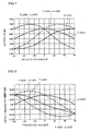
- Fig. 7 shows an output on the X axis, an output on the Y axis, the output on the Y axis - the output on the X axis, and the output on the Y axis + the output on the X axis with respect to inclination angle ⁇ on this occasion
- Fig. 8 shows changes in the outputs per 1° (an output equivalent to gravity acceleration is indicated as A).
- an absolute value of the change in the output on the Y axis - the output on the X axis at an angle close to +45° and an absolute value of the change in the output on the Y axis + the output on the X axis at an angle close to -45° are greater than absolute values of the changes in the outputs on the X axis and the Y axis.
- the absolute value of the change in the output on the X axis or the Y axis is 12.23 ⁇ 10 -3 A/°
- the absolute value of the change in the output on the Y axis - the output on the X axis or the output on the Y axis + the output on the X axis is 24.68 ⁇ 10 -3 A/°, which is about twice greater than the former value.
- an inclination angle for example close to ⁇ 45° can be detected with high accuracy by obtaining the sum of or the difference between the outputs on the X axis and the Y axis.
- the technique to obtain the difference between the outputs on the two axes such as the output on the Y axis - the output on the X axis, can be expected to cancel a noise component or a thermal characteristic component of the output on each axis, inclination accuracy is improved and a desirable effect can be obtained.
- Fig. 9 schematically illustrates an arrangement (orientation) when an acceleration sensor 110 in accordance with a second embodiment of the present invention is installed in an apparatus.
- the basic structure of sensor 110 in the present embodiment is the same as that of sensor 10 in the first embodiment described above, except for a relative positional relation with the mounting board and the apparatus to be installed.
- SP indicates a standard plane when the apparatus equipped with sensor 110 is in a basic position
- numerals 112, 114, and 116 correspond to silicon substrate 12, movable structural portion 14, and beam 16 in the first embodiment, respectively.
- a detection plane (114) of sensor 110 stands vertical.
- the detection axis Z orthogonal to the detection axes X and Y in the detection plane (114) is disposed in parallel with standard plane SP of the apparatus in the basic position. Then, inclined displacement of standard surface SP is determined based on a difference between or a sum of an output signal on the detection axis and an output signal on the detection axis Y, and the inclined displacement is corrected if necessary.
- the detection axes X and Y orthogonal to each other are each disposed to form an angle of 45° with respect to standard plane SP. It is to be noted that the angle between the detection axis X or Y and standard plane SP is not limited to 45°, and can be changed as appropriate.
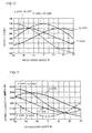
- Fig. 10 shows an output on the X axis, an output on the Y axis, the output on the Y axis - the output on the X axis, and the output on the Y axis + the output on the X axis with respect to inclination angle ⁇ .
- Fig. 11 shows changes in the outputs per 1° when an output equivalent to gravity acceleration is indicated as A.
- the change in the output on the X axis or the Y axis at an angle close to ⁇ 45° is increased by disposing the sensor to be inclined at 45°. As a result, accuracy in detecting inclination can be improved.
- an absolute value of the output on the X axis or the Y axis is 12.23 ⁇ 10 -3 A/° in the first embodiment
- an absolute value of the output on the X axis or the Y axis is 17.60 ⁇ 10 -3 A/° in the present embodiment, which is about 1.44 times greater than the former value.
- the output on the Y axis - the output on the X axis has the greatest value, which is 24.68 ⁇ 10 -3 A/° in an absolute value, about twice greater than an absolute value of 12.45 ⁇ 10 -3 A/° of the X axis or the Y axis.
- the output on the Y axis + the output on the X axis has the greatest value, which is 24.68 ⁇ 10 -3 A/° in an absolute value, about twice greater than an absolute value of 12.23 ⁇ 10 -3 A/° of the X axis or the Y axis.
- an inclination angle for example close to 0°, ⁇ 90° can be detected with high accuracy by obtaining the sum of or the difference between the outputs on the X axis and the Y axis.
- the technique to obtain the difference between the outputs on the two axes such as the output on the Y axis - the output on the X axis, can be expected to cancel a noise component or a thermal characteristic component of the output on each axis, inclination accuracy is improved and a desirable effect can be obtained.
- Acceleration sensor 110 in accordance with the present embodiment is mounted on mounting board 100 as shown in Fig. 12. Then, as shown in Fig. 13, mounting board 100 is used to stand vertical to apparatus 200 such as a projector, a head mounted display, a portable game apparatus, or a game controller. Sensor chip 110 is mounted on mounting board 100 such that two orthogonal detection axes are inclined at 45° from the vertical and from the horizontal with respect to each edge of mounting board 100.
- Fig. 14 is a schematic view illustrating a direction (an orientation) in which an acceleration sensor 210 in accordance with a third embodiment of the present invention is installed in an apparatus.
- SP indicates a standard plane when the apparatus equipped with sensor 210 is in a basic position
- numerals 212, 214, and 216 correspond to silicon substrate 12, movable structural portion 14, and beam 16 in the first embodiment, respectively.
- a detection plane (214) of sensor 210 stands vertical.
- the detection axis Z orthogonal to the detection axes X and Y in the detection plane (214) is disposed in parallel with standard plane SP of the apparatus in the basic position.
- inclined displacement of standard surface SP is determined based on a difference between or a sum of an output signal on the detection axis X and an output signal on the detection axis Y, and the inclined displacement is corrected if necessary.
- Mounting the acceleration sensor to form an angle of 45° with respect to standard plane SP of the apparatus may cause a problem such as occupying a large area on a printed board or a problem in terms of accuracy in a mounting angle.
- a problem can be solved by using a semiconductor piezoresistance acceleration sensor made of a silicon substrate with a (110) plane as shown in Fig. 14.
Landscapes
- Physics & Mathematics (AREA)
- General Physics & Mathematics (AREA)
- Engineering & Computer Science (AREA)
- Radar, Positioning & Navigation (AREA)
- Remote Sensing (AREA)
- Pressure Sensors (AREA)
- Length Measuring Devices With Unspecified Measuring Means (AREA)
Applications Claiming Priority (3)
| Application Number | Priority Date | Filing Date | Title |
|---|---|---|---|
| JP2003033016 | 2003-02-10 | ||
| JP2003033016A JP2004264053A (ja) | 2003-02-10 | 2003-02-10 | 加速度センサ及び傾斜検出方法 |
| PCT/JP2004/001444 WO2004081584A1 (ja) | 2003-02-10 | 2004-02-10 | 加速度センサ及び傾斜検出方法 |
Publications (2)
| Publication Number | Publication Date |
|---|---|
| EP1598673A1 true EP1598673A1 (de) | 2005-11-23 |
| EP1598673A4 EP1598673A4 (de) | 2007-07-11 |
Family
ID=32984306
Family Applications (1)
| Application Number | Title | Priority Date | Filing Date |
|---|---|---|---|
| EP04709748A Withdrawn EP1598673A4 (de) | 2003-02-10 | 2004-02-10 | Beschleunigungssensor und neigungserfassungsverfahren |
Country Status (8)
| Country | Link |
|---|---|
| US (1) | US7428841B2 (de) |
| EP (1) | EP1598673A4 (de) |
| JP (1) | JP2004264053A (de) |
| KR (1) | KR100771458B1 (de) |
| CN (1) | CN1748146A (de) |
| NO (1) | NO20054191L (de) |
| TW (1) | TWI268624B (de) |
| WO (1) | WO2004081584A1 (de) |
Cited By (1)
| Publication number | Priority date | Publication date | Assignee | Title |
|---|---|---|---|---|
| CN106142051A (zh) * | 2016-07-26 | 2016-11-23 | 南京林业大学 | 台体型并联机构及其位置正解的求解方法 |
Families Citing this family (24)
| Publication number | Priority date | Publication date | Assignee | Title |
|---|---|---|---|---|
| KR100702055B1 (ko) * | 2005-03-09 | 2007-04-02 | 인피닉스 주식회사 | 디지털 수평 측정기구 |
| KR100777404B1 (ko) * | 2005-12-30 | 2007-11-19 | 재단법인서울대학교산학협력재단 | 두 개의 가속도 센서를 이용한 각속도 측정방법 및 장치 |
| JP5043358B2 (ja) | 2006-04-04 | 2012-10-10 | ラピスセミコンダクタ株式会社 | 傾斜角演算方法及び傾斜角演算装置 |
| US7870678B2 (en) | 2006-09-06 | 2011-01-18 | Samsung Electro-Mechanics Co., Ltd. | Hybrid sensor module and sensing method using the same |
| JP4607848B2 (ja) * | 2006-10-27 | 2011-01-05 | 東京エレクトロン株式会社 | 基板処理装置、基板受け渡し位置の調整方法及び記憶媒体 |
| JP2008281351A (ja) * | 2007-05-08 | 2008-11-20 | Denso Corp | 電子装置 |
| KR100908124B1 (ko) * | 2007-07-09 | 2009-07-16 | 삼성전자주식회사 | 혈압측정용 압력 센서 및 그 제조방법 |
| CN101620237B (zh) * | 2009-08-10 | 2014-09-10 | 上海闻泰电子科技有限公司 | 一种加速度传感器倾斜动作的判断方法 |
| CN102168971B (zh) * | 2010-12-24 | 2012-12-05 | 郑州辰维科技股份有限公司 | 交会对接运动模拟器二维倾斜测量系统 |
| TW201314089A (zh) | 2011-09-26 | 2013-04-01 | Rui-Qian Chen | 用於水龍頭之監測裝置、具有監測裝置之水龍頭及其監測方法 |
| CN103675345B (zh) | 2012-09-21 | 2017-12-01 | 中国科学院地质与地球物理研究所 | 一种加速度计及其制造工艺 |
| CN103675346B (zh) | 2012-09-21 | 2018-03-06 | 中国科学院地质与地球物理研究所 | 一种加速度计及其制造工艺 |
| CN104166016B (zh) | 2013-05-16 | 2016-06-01 | 中国科学院地质与地球物理研究所 | 一种高灵敏度三轴mems加速度计及其制造工艺 |
| JP6212387B2 (ja) * | 2013-12-27 | 2017-10-11 | 株式会社ケーヒン | 鞍乗り型車両の傾斜角検出装置 |
| CN104006788A (zh) * | 2014-05-23 | 2014-08-27 | 深圳市元征科技股份有限公司 | 汽车dlc插座方向检测的方法 |
| CN106461394A (zh) | 2014-06-26 | 2017-02-22 | 路梅戴尼科技公司 | 用于从非线性周期信号确定旋转的系统和方法 |
| US9612251B2 (en) * | 2014-09-30 | 2017-04-04 | Meng Liang Chen | G-force measurement system with a horizontally deviated accelerometer |
| TWI650558B (zh) | 2015-05-20 | 2019-02-11 | 美商路梅戴尼科技公司 | 用於決定慣性參數之方法及系統 |
| JP2016217980A (ja) * | 2015-05-25 | 2016-12-22 | 清水建設株式会社 | 傾斜計 |
| US10234477B2 (en) | 2016-07-27 | 2019-03-19 | Google Llc | Composite vibratory in-plane accelerometer |
| JP7023171B2 (ja) * | 2018-05-01 | 2022-02-21 | アルプスアルパイン株式会社 | 角度検知センサ及び角度検知センサに用いられる成形体の製造方法 |
| CN109596141A (zh) * | 2019-01-22 | 2019-04-09 | 广州极飞科技有限公司 | 传感器组件、惯性测量组件和移动设备 |
| JP7177722B2 (ja) * | 2019-02-20 | 2022-11-24 | シチズン時計株式会社 | 携帯機器 |
| JP7574638B2 (ja) | 2020-12-18 | 2024-10-29 | 東京エレクトロン株式会社 | 基板を搬送する装置及び基板を処理するシステム並びに基板を搬送する方法。 |
Family Cites Families (20)
| Publication number | Priority date | Publication date | Assignee | Title |
|---|---|---|---|---|
| US4831558A (en) * | 1986-08-26 | 1989-05-16 | The Slope Indicator Company | Digitally based system for monitoring physical phenomena |
| JPS63266359A (ja) * | 1987-04-24 | 1988-11-02 | Nekushii Kenkyusho:Kk | 加速度・傾斜度検出装置 |
| JP2681215B2 (ja) | 1989-05-29 | 1997-11-26 | 株式会社ワコー | 積層基板を用いたセンサの製造方法 |
| JPH03105255A (ja) | 1989-09-19 | 1991-05-02 | Ricoh Co Ltd | 加速度測定装置 |
| JPH03107767A (ja) | 1989-09-21 | 1991-05-08 | Ricoh Co Ltd | 加速度センサ |
| JPH06151887A (ja) | 1992-11-02 | 1994-05-31 | Fujikura Ltd | 半導体加速度センサの製造方法 |
| JP2877034B2 (ja) | 1994-06-15 | 1999-03-31 | 株式会社デンソー | 加速度検出装置および加速度センサ |
| US5835077A (en) * | 1995-01-13 | 1998-11-10 | Remec, Inc., | Computer control device |
| US5866818A (en) * | 1995-11-30 | 1999-02-02 | Matsushita Electric Works, Ltd. | Acceleration sensor device |
| DE19637079C2 (de) * | 1996-09-12 | 2000-05-25 | Telefunken Microelectron | Anordnung zur Beschleunigungsmessung |
| US6332359B1 (en) | 1997-04-24 | 2001-12-25 | Fuji Electric Co., Ltd. | Semiconductor sensor chip and method for producing the chip, and semiconductor sensor and package for assembling the sensor |
| JPH11183504A (ja) | 1997-12-22 | 1999-07-09 | Nec Home Electron Ltd | 車載加速度計測装置 |
| JP2000206136A (ja) | 1999-01-13 | 2000-07-28 | Sumitomo Precision Prod Co Ltd | 車両の速度、走行距離と路面勾配の計測方法とその装置 |
| US6115261A (en) * | 1999-06-14 | 2000-09-05 | Honeywell Inc. | Wedge mount for integrated circuit sensors |
| JP2001099646A (ja) | 1999-10-01 | 2001-04-13 | Omron Corp | 傾き検出装置 |
| JP2001311621A (ja) | 2000-04-28 | 2001-11-09 | Omron Corp | 傾斜センサユニット |
| JP4178722B2 (ja) * | 2000-06-21 | 2008-11-12 | コニカミノルタホールディングス株式会社 | 光学異方体 |
| US20020109673A1 (en) | 2001-01-04 | 2002-08-15 | Thierry Valet | Method and apparatus employing angled single accelerometer sensing multi-directional motion |
| JP4174979B2 (ja) * | 2001-07-13 | 2008-11-05 | 松下電工株式会社 | 加速度センサ |
| US6634113B1 (en) * | 2002-05-17 | 2003-10-21 | Delphi Technologies, Inc. | Tilt sensor and method of forming such device |
-
2003
- 2003-02-10 JP JP2003033016A patent/JP2004264053A/ja active Pending
-
2004
- 2004-02-10 EP EP04709748A patent/EP1598673A4/de not_active Withdrawn
- 2004-02-10 CN CNA2004800039167A patent/CN1748146A/zh active Pending
- 2004-02-10 US US10/545,088 patent/US7428841B2/en not_active Expired - Fee Related
- 2004-02-10 KR KR1020057014663A patent/KR100771458B1/ko not_active Expired - Fee Related
- 2004-02-10 WO PCT/JP2004/001444 patent/WO2004081584A1/ja not_active Ceased
- 2004-02-10 TW TW093103066A patent/TWI268624B/zh not_active IP Right Cessation
-
2005
- 2005-09-09 NO NO20054191A patent/NO20054191L/no not_active Application Discontinuation
Cited By (2)
| Publication number | Priority date | Publication date | Assignee | Title |
|---|---|---|---|---|
| CN106142051A (zh) * | 2016-07-26 | 2016-11-23 | 南京林业大学 | 台体型并联机构及其位置正解的求解方法 |
| CN106142051B (zh) * | 2016-07-26 | 2018-06-26 | 南京林业大学 | 台体型并联机构及其位置正解的求解方法 |
Also Published As
| Publication number | Publication date |
|---|---|
| EP1598673A4 (de) | 2007-07-11 |
| TW200425526A (en) | 2004-11-16 |
| KR20050098310A (ko) | 2005-10-11 |
| JP2004264053A (ja) | 2004-09-24 |
| CN1748146A (zh) | 2006-03-15 |
| TWI268624B (en) | 2006-12-11 |
| KR100771458B1 (ko) | 2007-10-31 |
| NO20054191L (no) | 2005-10-11 |
| WO2004081584A1 (ja) | 2004-09-23 |
| US7428841B2 (en) | 2008-09-30 |
| US20060162450A1 (en) | 2006-07-27 |
| NO20054191D0 (no) | 2005-09-09 |
Similar Documents
| Publication | Publication Date | Title |
|---|---|---|
| US7428841B2 (en) | Acceleration sensor and inclination-detecting method | |
| US7367232B2 (en) | System and method for a three-axis MEMS accelerometer | |
| EP2431722A2 (de) | MEMS-Sensor mit Beschleunigungs- und Druckmessfähigkeit | |
| KR100499970B1 (ko) | 가속도 센서 | |
| US20080034867A1 (en) | Multi-range three-axis acceleration sensor device | |
| US11473987B2 (en) | Sensor chip and force sensor device | |
| JP5140291B2 (ja) | 動きセンサ | |
| US7104128B2 (en) | Multiaxial micromachined differential accelerometer | |
| EP4220191A1 (de) | Beschleunigungsmesser, trägheitsmesseinheit und elektronische vorrichtung | |
| US7281427B2 (en) | Acceleration sensor | |
| EP1298442A1 (de) | Beschleunigungssensor | |
| US20150355220A1 (en) | Inertial sensor module having hermetic seal formed of metal and multi-axis sensor employing the same | |
| EP1348967A2 (de) | Beschleunigungsaufnehmer | |
| JPH08504035A (ja) | 力成分を測定する単結晶材料製のデバイスおよびこのデバイスの製造方法およびこのデバイスの使用方法 | |
| EP3323778B1 (de) | Mems-vorrichtung und verfahren zur kalibrierung einer mems-vorrichtung | |
| JP2013044645A (ja) | 物理量センサのサブマウントmidパッケージ | |
| JP2006098323A (ja) | 半導体型3軸加速度センサ | |
| JPH1010148A (ja) | 半導体姿勢センシングチップ | |
| JP2004069405A5 (de) | ||
| JP3171970B2 (ja) | 力/加速度の検出装置 | |
| JPH08160070A (ja) | 加速度センサ | |
| JPH06163938A (ja) | 半導体振動・加速度検出装置 | |
| JP5046240B2 (ja) | 加速度センサの製造方法 | |
| US20150007657A1 (en) | Inertial sensor and method of manufacturing the same | |
| JPH08160067A (ja) | 加速度センサ |
Legal Events
| Date | Code | Title | Description |
|---|---|---|---|
| PUAI | Public reference made under article 153(3) epc to a published international application that has entered the european phase |
Free format text: ORIGINAL CODE: 0009012 |
|
| 17P | Request for examination filed |
Effective date: 20050906 |
|
| AK | Designated contracting states |
Kind code of ref document: A1 Designated state(s): AT BE BG CH CY CZ DE DK EE ES FI FR GB GR HU IE IT LI LU MC NL PT RO SE SI SK TR |
|
| AX | Request for extension of the european patent |
Extension state: AL LT LV MK |
|
| DAX | Request for extension of the european patent (deleted) | ||
| A4 | Supplementary search report drawn up and despatched |
Effective date: 20070611 |
|
| 17Q | First examination report despatched |
Effective date: 20070904 |
|
| GRAP | Despatch of communication of intention to grant a patent |
Free format text: ORIGINAL CODE: EPIDOSNIGR1 |
|
| STAA | Information on the status of an ep patent application or granted ep patent |
Free format text: STATUS: THE APPLICATION IS DEEMED TO BE WITHDRAWN |
|
| 18D | Application deemed to be withdrawn |
Effective date: 20110531 |