EP1598280A1 - Flaschenausguss - Google Patents
Flaschenausguss Download PDFInfo
- Publication number
- EP1598280A1 EP1598280A1 EP04714024A EP04714024A EP1598280A1 EP 1598280 A1 EP1598280 A1 EP 1598280A1 EP 04714024 A EP04714024 A EP 04714024A EP 04714024 A EP04714024 A EP 04714024A EP 1598280 A1 EP1598280 A1 EP 1598280A1
- Authority
- EP
- European Patent Office
- Prior art keywords
- spout
- bottle
- partition
- air
- liquid effluent
- Prior art date
- Legal status (The legal status is an assumption and is not a legal conclusion. Google has not performed a legal analysis and makes no representation as to the accuracy of the status listed.)
- Withdrawn
Links
Images


Classifications
-
- B—PERFORMING OPERATIONS; TRANSPORTING
- B65—CONVEYING; PACKING; STORING; HANDLING THIN OR FILAMENTARY MATERIAL
- B65D—CONTAINERS FOR STORAGE OR TRANSPORT OF ARTICLES OR MATERIALS, e.g. BAGS, BARRELS, BOTTLES, BOXES, CANS, CARTONS, CRATES, DRUMS, JARS, TANKS, HOPPERS, FORWARDING CONTAINERS; ACCESSORIES, CLOSURES, OR FITTINGS THEREFOR; PACKAGING ELEMENTS; PACKAGES
- B65D23/00—Details of bottles or jars not otherwise provided for
- B65D23/04—Means for mixing or for promoting flow of contents
-
- B—PERFORMING OPERATIONS; TRANSPORTING
- B65—CONVEYING; PACKING; STORING; HANDLING THIN OR FILAMENTARY MATERIAL
- B65D—CONTAINERS FOR STORAGE OR TRANSPORT OF ARTICLES OR MATERIALS, e.g. BAGS, BARRELS, BOTTLES, BOXES, CANS, CARTONS, CRATES, DRUMS, JARS, TANKS, HOPPERS, FORWARDING CONTAINERS; ACCESSORIES, CLOSURES, OR FITTINGS THEREFOR; PACKAGING ELEMENTS; PACKAGES
- B65D1/00—Rigid or semi-rigid containers having bodies formed in one piece, e.g. by casting metallic material, by moulding plastics, by blowing vitreous material, by throwing ceramic material, by moulding pulped fibrous material or by deep-drawing operations performed on sheet material
- B65D1/02—Bottles or similar containers with necks or like restricted apertures, designed for pouring contents
- B65D1/0223—Bottles or similar containers with necks or like restricted apertures, designed for pouring contents characterised by shape
- B65D1/023—Neck construction
-
- B—PERFORMING OPERATIONS; TRANSPORTING
- B65—CONVEYING; PACKING; STORING; HANDLING THIN OR FILAMENTARY MATERIAL
- B65D—CONTAINERS FOR STORAGE OR TRANSPORT OF ARTICLES OR MATERIALS, e.g. BAGS, BARRELS, BOTTLES, BOXES, CANS, CARTONS, CRATES, DRUMS, JARS, TANKS, HOPPERS, FORWARDING CONTAINERS; ACCESSORIES, CLOSURES, OR FITTINGS THEREFOR; PACKAGING ELEMENTS; PACKAGES
- B65D25/00—Details of other kinds or types of rigid or semi-rigid containers
- B65D25/38—Devices for discharging contents
- B65D25/40—Nozzles or spouts
- B65D25/48—Separable nozzles or spouts
-
- B—PERFORMING OPERATIONS; TRANSPORTING
- B65—CONVEYING; PACKING; STORING; HANDLING THIN OR FILAMENTARY MATERIAL
- B65D—CONTAINERS FOR STORAGE OR TRANSPORT OF ARTICLES OR MATERIALS, e.g. BAGS, BARRELS, BOTTLES, BOXES, CANS, CARTONS, CRATES, DRUMS, JARS, TANKS, HOPPERS, FORWARDING CONTAINERS; ACCESSORIES, CLOSURES, OR FITTINGS THEREFOR; PACKAGING ELEMENTS; PACKAGES
- B65D47/00—Closures with filling and discharging, or with discharging, devices
- B65D47/04—Closures with discharging devices other than pumps
- B65D47/32—Closures with discharging devices other than pumps with means for venting
Definitions
- This invention relates to a bottle spout. More particularly this invention relates to a spout of a bottle or other such container, which permits comfortable swallow or smooth pour of the liquid held therein.
- JP ⁇ A HEI 10-119974 proposes a spouting aid which is constructed by forming a partition adapted to divide the spout of a bottle for a drink and directed toward the interior of the bottle and concealing one of the divided parts of the spout with a covering part provided with a ventilating hole so as to prevent the drink from producing a swirling motion and flowing out on the ventilating hole side.
- This invention has been initiated in the light of such a true state of affairs as mentioned above. It is aimed at providing a bottle spout that ensures a smooth outflow of the drink held in the bottle and befits the purpose of allowing a consumer to take the drink from the bottle by directly applying his mouth to the spout of the bottle.
- the present invention provides a spout of a bottle having a partition integrated therewith for dividing a space inside the spout into a liquid effluent part and an air influent part, which are opened toward an outer direction in an opening face of the spout, the partition having a part that extends on a side of the air influent part toward an interior of the bottle and is continued to an inner wall of the spout and closed in a bag form, and having in a trailing part thereof an air hole that connects the air influent part and the interior of the bottle.
- the present invention further provides a spout of a bottle having a partition integrated therewith in an anterior part thereof for dividing a space inside the spout into a liquid effluent part and an air influent part, which are opened toward an outer direction in an opening face of the spout, the partition having a part that extends on a side of the air influent part toward an interior of the bottle and is continued to an inner wall of the spout and closed in a bag form, having in a trailing part thereof an air hole that connects the air influent part and the interior of the bottle and having in a posterior part thereof a mounting part that mounts the spout onto a spout of a ready-made bottle.
- the partition has an anterior terminal face formed in a circular shape having a diameter smaller than that of the spout or in a shape having a central part thereof curved upwardly in a state wherein the air influent part falls above the liquid effluent part.
- the partition has an anterior terminal face curved inwardly of the interior of the bottle.
- the drink is smoothly and continuously poured into the mouth because no collision occurs between the drink flowing out and the air flowing in as described above. Therefore, the user swallows the drink decently and contentedly without overflowing his mouth.
- the spout of the construction described above is provided in the posterior part thereof with a mounting part that is capable of easily mounting the spout of the aforementioned construction onto a spout of a ready-made bottle, the drinking water in the ready-made bottle can be likewise swallowed or discharged to the exterior without threatening any bounce thereof.
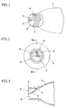
- Fig. 1 is a perspective view illustrating the basic construction of a spout 2 of this invention integrated with a main body 1 of a bottle
- Fig. 2 is a front view thereof
- Fig. 3 is a cross section taken through Fig. 2 along line III-III.
- the spout 2 is provided with a partition 3 for dividing the space inside the spout into a liquid effluent part 5 and an air influent part 6, the partition being integrated with the spout, the liquid effluent part 5 side and the air influent part 6 side both being opened toward the outer direction in the opening face of the spout, the partition 3 being integrated with the inner wall of the spout 2 and closed on the air influent, part 6 side in the form of a bag, and the partition 3 being provided in the trailing terminal thereof with an air hole 4 serving as a passage for advancing air from the air influent part 6 to the interior of the bottle.
- the user when the user wraps the fluid effluent part of the bottle with his mouth in such a manner that his upper lip may naturally enter the spout on the air influent part side, he can swallow the drink easily.
- the user For the purpose of releasing the liquid held in the bottle provided with the spout of the aforementioned construction, the user is required to tilt the bottle so that the air influent part may rise and the liquid effluent part may fall. Consequently, the liquid in the bottle starts toward the exterior of the bottle through the liquid effluent part and the space consequently formed in the bottle admits the air via the air hole disposed at the trailing terminal of the partition owing to the difference of air pressure.
- the liquid is smoothly and continuously released without producing an undulating motion in the neighborhood of the spout.
- the shape and size of the liquid effluent part 5 of the spout described above and the position, size, shape and number of the air hole 4 may be freely decided, depending on the kind of the drinking water and the size and design of the spout.
- the shape of the air hole for example, does not need to be restricted to a perfect circle but may be selected from among various shapes, such as ellipse, triangle, pentagram and heart to suit the purpose of use of the bottle or container.
- the number of air hole does not need to be limited to one.
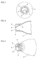
- a plurality of air holes may be disposed to suit the purpose of use of the bottle as illustrated in Fig. 4.
- the air hole is preferred to be large for the purpose of enabling the user to swallow the drink in a large amount at a time.
- the provision of a plurality of small air holes 4 as illustrated in Fig. 4 serves the purpose of suppressing the leakage of the drink.
- the position of the partition 3 disposed in the spout 2 of the bottle mentioned above is so selected as to intersect the center of the spout in the construction of Fig. 1.
- this position is so selected as to fall upward from the center as illustrated in Fig. 5
- the liquid effluent part 5 is allowed to occupy a large volume and assume a shape suitable for rapid swallow of the drink in a large amount.
- the partition is positioned downward from the center conversely from the preceding case, the liquid effluent part 5 assumes a shape suitable for swallowing the drink in a small amount.
- the liquid effluent part 5 assumes a shape resembling the shape of the user's mouth, allowing the liquid to gather copiously near the center of the liquid effluent part and enabling the user to swallow the drink in the bottle contentedly without spilling the drink.
- the liquid effluent part 5 fits easy wrap with the user's mouth, allows control of the amount of the drink to be released and permits even a female user or an infant user to take the drink without spilling it. Even in a vehicle in motion, this liquid effluent part 5 enables the user to swallow the drink similarly contentedly without spilling the drink.
- the partition can adopt an optimum shape to suit the kind of the drink, the purpose of use and the kind of the user, for example.
- the partition 3 has a curved cross section in the example illustrated in Fig. 3. It may have a planar cross section instead as illustrated in Fig. 8.
- the anterior terminal face of the partition 3 disposed in the spout which is touched by the user's mouth is given a shape dented and curved inwardly of the interior of the bottle, the user's upper lip fits in the dent and the opened terminal of the liquid effluent part is naturally covered wholly by the mouth so as to add further to the ease with which the drink inside the bottle is swallowed by the user.
- the air hole 4 provided in the trailing terminal of the partition 3 may be produced in advance by piercing at the time of production of the bottle.
- it may be formed by piercing at the time of removing the plug from the bottle.
- a method which comprises closing the part of the air hole 4 with a seal applied thereto on the air influent part 6 side and peeling this seal at the time the drink is used and a method which comprises forming the air hole 4 part in an easily cuttable contour in advance and clipping the air hole 4 part at the time of unplugging the bottle may be cited, for example.
- the preceding examples invariably contemplate a spout of a bottle 1 which has a partition 3 directly formed in the spout of the bottle and has given rise to a liquid effluent part 5 and an air influent part 6.
- the front face of the spout is depicted in a circular shape.
- the shape of the front face does not need to be restricted to such a circle but is only required to permit provision of a partition serving to divide the inner space of the spout into a fluid effluent part and an air influent part.
- the shape may be properly selected from among various shapes, such as ellipse, triangle, lemon and lips of a mouth, for example.
- the spout of this invention for a bottle has the open face thereof divided by a partition into a liquid effluent part and an air influent part as described above.
- the drink in the bottle flows into the user's mouth through the liquid effluent part.
- the space formed inside the bottle immediately admits the air via the air hole formed in the air influent part. Since the pressure is constantly retained equally inside and outside the bottle, the drink is smoothly poured into the user's mouth continuously through the liquid effluent part without leaking through the gap between the mouth and the spout or producing an undulating motion in the neighborhood of the spout.
- the user is enabled to swallow the drink easily and decently.
- the bottle that is provided with the spout of this invention has only to be tilted till the liquid effluent part is lowered in order that the liquid held therein may be smoothly released through the liquid effluent part.
- it can be utilized advantageously when the liquid is transferred from a large bottle into a small bottle, for example.
- the spout of this invention for a bottle embraces being provided with a mounting part that can be easily mounted onto a spout of a ready-made bottle.
Landscapes
- Engineering & Computer Science (AREA)
- Mechanical Engineering (AREA)
- Ceramic Engineering (AREA)
- Details Of Rigid Or Semi-Rigid Containers (AREA)
- Closures For Containers (AREA)
- Containers Having Bodies Formed In One Piece (AREA)
Applications Claiming Priority (5)
| Application Number | Priority Date | Filing Date | Title |
|---|---|---|---|
| JP2003098664 | 2003-02-25 | ||
| JP2003098664 | 2003-02-25 | ||
| JP2003136595A JP3520448B1 (ja) | 2003-02-25 | 2003-04-08 | 飲料用瓶の注ぎ口 |
| JP2003136595 | 2003-04-08 | ||
| PCT/JP2004/002147 WO2004076304A1 (ja) | 2003-02-25 | 2004-02-24 | 瓶の注ぎ口 |
Publications (3)
| Publication Number | Publication Date |
|---|---|
| EP1598280A1 true EP1598280A1 (de) | 2005-11-23 |
| EP1598280A8 EP1598280A8 (de) | 2006-05-10 |
| EP1598280A4 EP1598280A4 (de) | 2008-12-24 |
Family
ID=32301872
Family Applications (1)
| Application Number | Title | Priority Date | Filing Date |
|---|---|---|---|
| EP04714024A Withdrawn EP1598280A4 (de) | 2003-02-25 | 2004-02-24 | Flaschenausguss |
Country Status (5)
| Country | Link |
|---|---|
| US (1) | US20060081662A1 (de) |
| EP (1) | EP1598280A4 (de) |
| JP (1) | JP3520448B1 (de) |
| KR (1) | KR100706426B1 (de) |
| WO (1) | WO2004076304A1 (de) |
Cited By (3)
| Publication number | Priority date | Publication date | Assignee | Title |
|---|---|---|---|---|
| DE102006009649A1 (de) * | 2006-03-02 | 2007-09-13 | Vurçak, Esat | EX-HALS (Trinken aus der Flasche ohne Pause) |
| ITMI20120769A1 (it) * | 2012-05-08 | 2013-11-09 | Ambrogio Enzo D | Contenitore per liquidi |
| WO2015004301A1 (es) * | 2013-07-08 | 2015-01-15 | Distintivo Patentes Y Marcas, S.L. | Dispositivo para el control de las turbulencias en el caudal de vaciado de un recipiente para líquidos |
Families Citing this family (20)
| Publication number | Priority date | Publication date | Assignee | Title |
|---|---|---|---|---|
| US20080210715A1 (en) * | 2005-03-10 | 2008-09-04 | Guruppo Pieta Co., Ltd | Spout Fitting Apparatus and Container |
| CA2606143A1 (en) * | 2005-04-19 | 2006-10-26 | Gravity Solutions Pty Ltd | Pouring aid |
| KR100836068B1 (ko) * | 2006-12-13 | 2008-06-09 | 백승권 | 액체용 용기의 속뚜껑 |
| DE102008014816B4 (de) | 2008-03-18 | 2012-09-06 | Julia Hübner | Vorrichtung zur Verbesserung des Ausgussverhaltens von Flaschen und flaschenähnlichen Behältern |
| US8684205B2 (en) | 2010-02-03 | 2014-04-01 | Paha Designs, Llc | Pressure equalization apparatus for a bottle and methods associated therewith |
| US8857639B2 (en) | 2010-02-03 | 2014-10-14 | Paha Designs, Llc | Pressure equalization apparatus for a bottle and methods associated therewith |
| US8602235B2 (en) * | 2010-02-03 | 2013-12-10 | Paha Designs, Llc | Pressure equalization apparatus for a bottle and methods associated therewith |
| US9796506B2 (en) | 2010-02-03 | 2017-10-24 | Paha Designs, Llc | Pressure equalization apparatus for a bottle and methods associated therewith |
| KR101370250B1 (ko) | 2012-05-17 | 2014-03-06 | 엘지전자 주식회사 | 냉장고용 아이스 메이커 |
| ES1078291Y (es) * | 2012-11-13 | 2013-03-22 | Tanio S A U | Tapón dosificador Bi-flujo |
| JP6147014B2 (ja) * | 2013-02-05 | 2017-06-14 | 株式会社テックスイージー | 瓶入り発泡飲料用泡立て装置 |
| US9878834B2 (en) | 2014-01-30 | 2018-01-30 | The Clorox Company | Smooth pour container |
| USD732395S1 (en) * | 2014-07-24 | 2015-06-23 | Allen Bobby Christian | Bottle |
| US12122572B2 (en) | 2017-03-13 | 2024-10-22 | Paha Designs, Llc | Pressure equalization apparatus for a container and methods associated therewith |
| JP6972399B2 (ja) * | 2017-06-09 | 2021-11-24 | ヤマハ発動機株式会社 | 鞍乗型車両用ハンドルパイプの製造方法 |
| US10472138B2 (en) * | 2017-10-12 | 2019-11-12 | Donny Smith | Systems and methods for a device with an internal vented nozzle |
| WO2019160938A1 (en) | 2018-02-13 | 2019-08-22 | Stackcan Llc | Container vent, dispenser and holding system |
| JP2019205400A (ja) * | 2018-05-30 | 2019-12-05 | 学校法人国士舘 | 細胞処理方法、デバイスおよびシステム |
| JP7825373B2 (ja) | 2020-01-31 | 2026-03-06 | 株式会社吉野工業所 | キャップ |
| US12408756B1 (en) | 2022-05-27 | 2025-09-09 | Series International, Llc | Stacking chair with removable back |
Family Cites Families (14)
| Publication number | Priority date | Publication date | Assignee | Title |
|---|---|---|---|---|
| US2424101A (en) * | 1943-05-15 | 1947-07-15 | Lari Ray Voir | Valved, slidable discharge tube |
| JPS3526185Y1 (de) * | 1957-12-05 | 1960-10-05 | ||
| US3040938A (en) * | 1958-02-17 | 1962-06-26 | Rieke Metal Products Corp | Vented pour spout |
| US3000544A (en) * | 1958-07-29 | 1961-09-19 | American Flange & Mfg | Vented pouring spouts for containers |
| US3863820A (en) * | 1973-11-08 | 1975-02-04 | Franklin Eugene Wharton | Pour spout |
| JPS6334034U (de) * | 1986-08-25 | 1988-03-04 | ||
| US4838464A (en) * | 1987-06-11 | 1989-06-13 | Graham Engineering Corporation | Vented plastic bottle |
| JPH0285154A (ja) * | 1988-09-12 | 1990-03-26 | Kunio Ono | 容器内の液圧差による排液むら防止装置並びにその装置用吸気管及びその製造方法 |
| US5377882A (en) * | 1990-09-04 | 1995-01-03 | Pham; Ninh G. | Container and closure |
| JPH09118338A (ja) * | 1995-10-26 | 1997-05-06 | Mamoru Umeyama | 吸気口を備えた壜およびその補助口 |
| JPH10119974A (ja) * | 1996-10-17 | 1998-05-12 | Sawa:Kk | 液体用容器の注口補助具 |
| AT409851B (de) * | 1999-03-15 | 2002-12-27 | Pack Pro Kunststoff Und Metall | Ausgiessvorrichtung für einen kanisterartigen behälter |
| JP2002173161A (ja) * | 2000-09-26 | 2002-06-18 | Shigeru Yamana | 整流栓 |
| MXPA04000234A (es) * | 2001-07-11 | 2005-03-07 | Procter & Gamble | Tubo de camaras multiples para despachar uniformemente. |
-
2003
- 2003-04-08 JP JP2003136595A patent/JP3520448B1/ja not_active Expired - Fee Related
-
2004
- 2004-02-24 EP EP04714024A patent/EP1598280A4/de not_active Withdrawn
- 2004-02-24 US US10/545,086 patent/US20060081662A1/en not_active Abandoned
- 2004-02-24 WO PCT/JP2004/002147 patent/WO2004076304A1/ja not_active Ceased
- 2004-02-24 KR KR1020057013738A patent/KR100706426B1/ko not_active Expired - Fee Related
Cited By (3)
| Publication number | Priority date | Publication date | Assignee | Title |
|---|---|---|---|---|
| DE102006009649A1 (de) * | 2006-03-02 | 2007-09-13 | Vurçak, Esat | EX-HALS (Trinken aus der Flasche ohne Pause) |
| ITMI20120769A1 (it) * | 2012-05-08 | 2013-11-09 | Ambrogio Enzo D | Contenitore per liquidi |
| WO2015004301A1 (es) * | 2013-07-08 | 2015-01-15 | Distintivo Patentes Y Marcas, S.L. | Dispositivo para el control de las turbulencias en el caudal de vaciado de un recipiente para líquidos |
Also Published As
| Publication number | Publication date |
|---|---|
| US20060081662A1 (en) | 2006-04-20 |
| KR20050097517A (ko) | 2005-10-07 |
| JP3520448B1 (ja) | 2004-04-19 |
| WO2004076304A1 (ja) | 2004-09-10 |
| JP2006044656A (ja) | 2006-02-16 |
| HK1088873A1 (en) | 2006-11-17 |
| KR100706426B1 (ko) | 2007-04-10 |
| EP1598280A8 (de) | 2006-05-10 |
| EP1598280A4 (de) | 2008-12-24 |
Similar Documents
| Publication | Publication Date | Title |
|---|---|---|
| EP1598280A1 (de) | Flaschenausguss | |
| EP2695549B1 (de) | Auslaufsicherer Getränkebehälter | |
| JP2010521388A (ja) | 飲用容器 | |
| JPH01121010A (ja) | 漏れ防止蓋 | |
| US7210596B1 (en) | Child's drinking cup | |
| US8146759B2 (en) | Fully vented wide rim nursing bottle with canted vent tube | |
| CN107985785A (zh) | 饮料容器 | |
| US20100108701A1 (en) | Splash-resistant drinking device | |
| US8579130B2 (en) | Fully vented wide rim nursing bottle with single piece vent insert | |
| JP2003506179A (ja) | 流出防止カップ | |
| CN206006755U (zh) | 一种防溅出的饮料杯 | |
| JP2013212863A (ja) | 飲料用容器の中栓体 | |
| JP4276726B2 (ja) | プッシュプルキャップ | |
| US11723483B2 (en) | Drink set having a calmed and restricted fluid flow | |
| US20200352369A1 (en) | Cup insert providing volume and flow regulation | |
| US12070142B2 (en) | Drinking vessel and lid for a drinking vessel | |
| CN109229847A (zh) | 一种设有回流腔的热饮杯盖 | |
| CA2611742C (en) | Fully vented wide rim nursing bottle with contoured vent tube | |
| US9339409B2 (en) | Women's portable urinal | |
| CN214179980U (zh) | 一种容器的盖本体及包含该盖本体的水杯 | |
| CN218355569U (zh) | 一种具有防泄漏功能的小口禅定杯 | |
| RU2840888C2 (ru) | Колпачок для контейнера для жидкости | |
| TW202543575A (zh) | 杯飲練習用飲料容器 | |
| TW202543529A (zh) | 飲用方法練習用飲料容器 | |
| JP2019182542A (ja) | 飲料用容器の飲み口 |
Legal Events
| Date | Code | Title | Description |
|---|---|---|---|
| PUAI | Public reference made under article 153(3) epc to a published international application that has entered the european phase |
Free format text: ORIGINAL CODE: 0009012 |
|
| 17P | Request for examination filed |
Effective date: 20050805 |
|
| AK | Designated contracting states |
Kind code of ref document: A1 Designated state(s): AT BE BG CH CY CZ DE DK EE ES FI FR GB GR HU IE IT LI LU MC NL PT RO SE SI SK TR |
|
| AX | Request for extension of the european patent |
Extension state: AL LT LV MK |
|
| RAP1 | Party data changed (applicant data changed or rights of an application transferred) |
Owner name: MIURA, NOBORU Owner name: MIURA, SHUICHI |
|
| DAX | Request for extension of the european patent (deleted) | ||
| A4 | Supplementary search report drawn up and despatched |
Effective date: 20081125 |
|
| 17Q | First examination report despatched |
Effective date: 20100312 |
|
| STAA | Information on the status of an ep patent application or granted ep patent |
Free format text: STATUS: THE APPLICATION IS DEEMED TO BE WITHDRAWN |
|
| 18D | Application deemed to be withdrawn |
Effective date: 20100723 |