EP1597186B1 - Rollsteig - Google Patents
Rollsteig Download PDFInfo
- Publication number
- EP1597186B1 EP1597186B1 EP04713456A EP04713456A EP1597186B1 EP 1597186 B1 EP1597186 B1 EP 1597186B1 EP 04713456 A EP04713456 A EP 04713456A EP 04713456 A EP04713456 A EP 04713456A EP 1597186 B1 EP1597186 B1 EP 1597186B1
- Authority
- EP
- European Patent Office
- Prior art keywords
- pallet
- area
- moving walkway
- pallets
- belt
- Prior art date
- Legal status (The legal status is an assumption and is not a legal conclusion. Google has not performed a legal analysis and makes no representation as to the accuracy of the status listed.)
- Expired - Lifetime
Links
- 239000000463 material Substances 0.000 claims description 3
- 230000001360 synchronised effect Effects 0.000 claims 1
- 230000000694 effects Effects 0.000 description 2
- 238000013459 approach Methods 0.000 description 1
- 230000008878 coupling Effects 0.000 description 1
- 238000010168 coupling process Methods 0.000 description 1
- 238000005859 coupling reaction Methods 0.000 description 1
- 230000001419 dependent effect Effects 0.000 description 1
- 238000011161 development Methods 0.000 description 1
- 230000018109 developmental process Effects 0.000 description 1
- 238000010586 diagram Methods 0.000 description 1
- 230000007246 mechanism Effects 0.000 description 1
Images


Classifications
-
- B—PERFORMING OPERATIONS; TRANSPORTING
- B66—HOISTING; LIFTING; HAULING
- B66B—ELEVATORS; ESCALATORS OR MOVING WALKWAYS
- B66B23/00—Component parts of escalators or moving walkways
- B66B23/02—Driving gear
- B66B23/026—Driving gear with a drive or carrying sprocket wheel located at end portions
-
- B—PERFORMING OPERATIONS; TRANSPORTING
- B66—HOISTING; LIFTING; HAULING
- B66B—ELEVATORS; ESCALATORS OR MOVING WALKWAYS
- B66B21/00—Kinds or types of escalators or moving walkways
- B66B21/10—Moving walkways
-
- B—PERFORMING OPERATIONS; TRANSPORTING
- B66—HOISTING; LIFTING; HAULING
- B66B—ELEVATORS; ESCALATORS OR MOVING WALKWAYS
- B66B23/00—Component parts of escalators or moving walkways
- B66B23/08—Carrying surfaces
- B66B23/10—Carrying belts
-
- B—PERFORMING OPERATIONS; TRANSPORTING
- B66—HOISTING; LIFTING; HAULING
- B66B—ELEVATORS; ESCALATORS OR MOVING WALKWAYS
- B66B23/00—Component parts of escalators or moving walkways
- B66B23/08—Carrying surfaces
- B66B23/12—Steps
Definitions
- the invention relates to a moving walkway, comprising a framework, which is provided for receiving a plurality of pallets, wherein the pallets have guide rollers and are movable via drive means in the transport direction.
- the DE-U 20 100 833 is an escalator or a moving walk with a step or pallet tape to be taken, which is driven by drive elements which extend on both sides of the belt or in the middle under the belt and which rotate between each a diverter wheel and a drive wheel, the steps or pallets depending on Driving points are driven on each drive element.
- the drive element is in this case designed as a toothed belt having blocks, wherein each block is connected to a step or pallet at the drive point.
- a double-sided timing belt drive comprising two motor driven pulleys each having a plurality of adjacent profiled teeth, a series of interconnected links each provided with a plurality of adjacent teeth and each connected to one of the steps a flexible pull-toothed belt having first and second sides each carrying a plurality of adjacent teeth of which the teeth of the first side mesh with the teeth of the pulleys and the teeth on the second side mesh linearly with the teeth of the links ,
- a pallet body for moving walks to remove consisting of a tread plate with toothed front and rear edges, connecting elements for receiving and guiding of connecting and / or drive members and Trittplattenab prolementen for receiving and guiding equipped with corresponding components preceding and subsequent pallet bodies, said the integrally formed with the tread plate connecting elements and the Trittplattenab spalemente are arranged below the same and protrude at a predetermined distance beyond the front and rear edges of the tread plate.
- the drive element is a conventional chain, in particular a link chain used. To minimize gaps between adjacent pallets, the teeth are provided intermeshingly.
- a passenger conveyor including a plurality of adjacent pallets, which are connected to each other via a pallet chain and are driven by selbige.
- the pallets are hingedly connected to one another via connecting elements in their areas of contact, wherein a plurality of rollers are provided in the region of each pallet side.
- EP-A 13792 a connecting means for pallets of a moving walkway, wherein the pallets outside the transport area are deflectable about a vertical axis, so that two parallel transport areas are formed. Outside the transport areas, the pallets are automatically separated by the connecting means, so that a problem-free deflection of the pallets is possible. Outside the transport areas, ie below the comb plates, a renewed automatic coupling of the individual pallets takes place, so that in the transport area then again the known continuous pallet strand is formed.
- the invention has the object of developing a generic type moving walkway to the effect that with stable guidance of the pallet strip a Connection between the individual pallets is no longer given, creating a low circulation height in the respective deflection of the individual pallets is possible.
- each pallet on each side is provided with a single guide roller, and that, seen in the transport direction, the rear portion of each pallet on a front portion of a subsequent range, forming a support area, supported, and that the Drive means are formed by at least one drive belt, which has lugs over which it can be brought into operative connection with corresponding components of the pallets.
- Each of the individual pallets is in the subject invention only at one point on each side connected to the drive means, in particular the respective drive belt. There is no further connection between the individual pallets.
- the advantage of this solution is that without taking into account the polygon effect, the individual pallets along a special guideway at low orbit height of the pallets can be easily redirected.
- the shape of the pallets is designed such that they support each other. This is realized by providing oppositely formed front and rear shoulders, wherein, as seen in the transport direction, the respective rear shoulder of a pallet rests on a corresponding front shoulder of a subsequent pallet.
- the heels are to be designed from their height so that no protrusions are formed in the transport area.
- In the pallets can be embedded in the support points beyond plastic elements that prevent noise when meshing the pallets.
- two synchronously running belts are advantageously used.
- the belts are deflected in the head region of the moving walkway by means of two synchronizing disks interconnected by a shaft.
- As a belt toothed, flat, wedge or round belts can be used.
- Attached on the back of the belt lugs are used to connect the individual pallets. Shape and design of the approaches can be performed in various ways.
- the connection of the pallets to the respective belt is carried out either via a fixed neck bolt connection or a loose connection in the form of a driver.
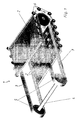
- FIG. 1 shows a circulating pallet strip 1, including a plurality of individual pallets 2, which are movable over a trained in this example as a toothed belt drive means 3 along a transport path.
- two synchronizing disks interconnected via a synchronizing shaft 4 are provided in the region of which the synchronously running toothed belts 3 are deflectable.
- Each pallet 2 has on each side a single guide roller 6, wherein the individual pallets 2 are not connected to each other.
- FIG. 2 shows one of the deflection areas. Recognizable are individual pallets 2, a synchronizing disk 5 and the toothed belt 3 and the guide rollers 6. It can also be seen from the respective toothed belt 3 pallet-shaped shaped projections 7, which are detachably connectable with correspondingly formed components 8 of each pallet 2.
- This low pallet circulation height can also cause no more pits need to be used to accommodate the scaffold body, but selbiges can be placed on the ground, with only a ramp low height is then necessary to enter the transport area.
- FIG. 3 shows the individual pallets 2, the associated (individual) guide rollers 6, the timing belt 3, the pallet side formed out of the timing belt 3 cam-like projections 7 and the corresponding molded in one piece from the pallets 2 Fastening elements 8.
- a detachable connection between the toothed belt 3 and the pallets 2 can be realized by means of a screw or bolt connection between the components 7 and 8.
- the transport direction is indicated by an arrow.
- the respective rear area of each pallet 2 is provided with a shoulder 9.
- the respective front region of a subsequent pallet is formed with an oppositely formed shoulder 10.
- the paragraphs 9,10 form a support area. In the respective support region 9,10 and the single guide roller 6 is arranged, which rolls on a guideway not shown here.
- the guide roller 6 is provided near the shoulder 10 in this example.
- each of the individual pallets 2 is connected in the proposed solution only at one point per side with the timing belt 3. There is no further connection between the individual pallets 2.
- the shoulders 9, 10 of the individual pallets 2 are designed such that they support one another.
- the front support portion 10 of each pallet 2 has a rounded free end 10 ', while the rear support portion 9 of each pallet 2 enters via a rounding 9' in the full material cross section of the pallet 2.
Landscapes
- Escalators And Moving Walkways (AREA)
- Magnetically Actuated Valves (AREA)
- Ultra Sonic Daignosis Equipment (AREA)
- Valve Device For Special Equipments (AREA)
- Structure Of Belt Conveyors (AREA)
- Handling Of Sheets (AREA)
- Moulds For Moulding Plastics Or The Like (AREA)
Description
- Die Erfindung betrifft einen Rollsteig, beinhaltend ein Gerüst, das zur Aufnahme einer Vielzahl von Paletten vorgesehen ist, wobei die Paletten Führungsrollen aufweisen und über Antriebsmittel in Transportrichtung bewegbar sind.
- Dem
DE-U 20 100 833 ist eine Fahrtreppe oder ein Fahrsteig mit einem Stufen- oder Palettenband zu entnehmen, das von Antriebselementen angetrieben ist, die sich beidseits des Bandes oder mittig unter dem Band erstrecken und die zwischen je einem Umlenkrad und einem Antriebsrad umlaufen, wobei die Stufen oder Paletten je an Antriebspunkten an jedem Antriebselement angetrieben sind. Das Antriebselement ist hierbei als Zahnriemen ausgebildet, der Blöcke aufweist, wobei je ein Block mit einer Stufe oder Palette an dem Antriebspunkt verbunden ist. - Durch die
DE-A 3 732 226 ist ein doppelseitiger Zahnriemenfahrtreppenantrieb bekannt geworden, beinhaltend zwei durch einen Motor antreibbare Riemenscheiben mit jeweils einer Vielzahl von nebeneinander liegenden profilierten Zähnen, eine Reihe von miteinander verbundenen Gliedern, die jeweils mit einer Vielzahl von nebeneinander liegenden Zähnen versehen und jeweils mit einer der Stufen verbunden sind und einen flexiblen Zugzahnriemen mit einer ersten und einer zweiten Seite, die jeweils eine Vielzahl von nebeneinander liegenden Zähnen tragen, von denen die Zähne der ersten Seite über einen Bogen mit den Zähnen der Riemenscheiben und die Zähne an der zweiten Seite linear mit den Zähnen der Glieder kämmen. - In der
US-A 3,365,051 wird ein Rollsteig beschrieben, der in seinen Kopfbereichen ohne Umlenkscheiben auskommt. Kopfseitig sind antreibbare Riemenelemente vorgesehen, die in entsprechend gezahnte Bereiche der Paletten eingreifen und das Antriebsmittel für den Rollsteig, respektive dessen Palettenband bilden. Die einzelnen Paletten sind über Rollen miteinander verbunden. - Der
US-A 6.085,891 ist ein Palettenkörper für Rollsteige zu entnehmen, bestehend aus einer Trittplatte mit verzahnten Vorder und Hinterkanten, Verbindungselementen zur Aufnahme und zur Führung von Verbindungs- und/oder Antriebsorganen sowie Trittplattenabstützelementen zur Aufnahme und zur Führung von mit korrespondierenden Bauteilen bestückten vorausgehenden bzw. nachfolgenden Palettenkörpern, wobei die einstückig mit der Trittplatte hergestellten Verbindungselemente und die Trittplattenabstützelemente unterhalb derselben angeordnet sind und mit vorgebbarem Abstand über die Vorder und Hinterkanten der Trittplatte hinausragen. Als Antriebsorgan kommt eine übliche Kette, insbesondere eine Laschenkette, zum Einsatz. Zur Minimierung von Spalten zwischen benachbarten Paletten sind die Verzahnungen ineinandergreifend vorgesehen. - In der
US-A 5,595,278 wird eine Personenfördereinrichtung beschrieben, beinhaltend eine Vielzahl benachbarter Paletten, die über eine Palettenkette miteinander verbunden sind und über selbige angetrieben werden. Die Paletten sind über Verbindungselemente in ihren Berührungsbereichen gelenkig miteinander verbunden, wobei mehrere Rollen im Bereich einer jeden Palettenseite vorgesehen sind. - Schließlich offenbart die
EP-A 13792 - Der Erfindung liegt die Aufgabe zugrunde, einen gattungsbildenden Rollsteig dahingehend weiterzubilden, dass bei stabiler Führung des Palettenbandes eine Verbindung zwischen den einzelnen Paletten nicht mehr gegeben ist, wodurch eine geringe Umlaufbauhöhe im jeweiligen Umlenkbereich der einzelnen Paletten möglich wird.
- Diese Aufgabe wird dadurch gelöst, dass eine jede Palette je Seite mit einer einzelnen Führungsrolle versehen ist, und dass, in Transportrichtung gesehen, sich der hintere Bereich einer jeden Palette auf einem vorderen Bereich einer nachfolgenden Palette, einen Stützbereich bildend, abstützt, und dass die Antriebsmittel durch mindestens einen Antriebsriemen gebildet sind, der über Ansätze verfügt, über welche er mit korrespondierenden Bauteilen der Paletten in Wirkverbindung bringbar ist.
- Vorteilhafte Weiterbildungen des Erfindungsgegenstandes sind den Unteransprüchen zu entnehmen.
- Jede der einzelnen Paletten ist beim Erfindungsgegenstand nur an einer Stelle je Seite mit dem Antriebsmittel, insbesondere dem jeweiligen Antriebsriemen, verbunden. Es besteht keine weitere Verbindung zwischen den einzelnen Paletten. Der Vorteil dieser Lösung ist darin begründet, dass ohne Berücksichtigung des Polygoneffektes die einzelnen Paletten entlang einer speziellen Führungsbahn bei geringer Umlaufhöhe der Paletten einfach umgelenkt werden können.
- Um eine Kippbewegung der nicht miteinander verbundenen Paletten im Bereich des Transportweges bzw. des Rücklaufes zu verhindern, ist die Form der Paletten dergestalt ausgelegt, dass sie sich gegenseitig abstützen. Dies wird dadurch realisiert, dass gegensinnig ausgebildete vordere und hintere Absätze vorgesehen werden, wobei, in Transportrichtung gesehen, der jeweilige hintere Absatz einer Palette auf einem korrespondierenden vorderen Absatz einer nachfolgenden Palette aufliegt. Die Absätze sind von ihrer Höhe her so auszugestalten, dass keine Überstände im Transportbereich gebildet werden. In den Paletten können an den Stützstellen darüber hinaus Kunststoffelemente eingelassen werden, die eine Geräuschentwicklung beim Ineinandergreifen der Paletten unterbinden.
- Zum Transport der einzelnen Paletten werden vorteilhafterweise zwei synchron laufende Riemen eingesetzt. Die Riemen werden im Kopfbereich des Rollsteiges über zwei, durch eine Welle miteinander verbundene Synchronscheiben umgelenkt. Als Riemen können sowohl Zahn-, Flach-, Keil- oder Rundriemen eingesetzt werden.
- Auf dem Rücken der Riemen aufgebrachte Ansätze dienen zur Anbindung der einzelnen Paletten. Form und Ausführung der Ansätze kann verschiedenartig ausgeführt werden. Die Anbindung der Paletten an den jeweiligen Riemen erfolgt entweder über eine feste Ansatz- Bolzenverbindung oder über eine lose Verbindung in Form eines Mitnehmers.
- Der Erfindungsgegenstand ist anhand eines Ausführungsbeispieles in der Zeichnung dargestellt und wird wie folgt beschrieben. Es zeigen
- Figur 1
- Prinzipskizze eines umlenkbaren Palettenbandes eines nicht weiter dargestellten Rollsteiges in perspektivischer Darstellung
- Figur 2
- Teildarstellung eines der Umlenkbereiche gemäß
Figur 1 - Figur 3
- Seitenansicht auf das umlaufende Palettenband samt Antriebsmitteln.
-
Figur 1 zeigt ein umlaufendes Palettenband 1, beinhaltend mehrere einzelne Paletten 2, die über ein in diesem Beispiel als Zahnriemen ausgebildetes Antriebsmittel 3 entlang einer Transportstrecke bewegbar sind. Im jeweiligen Umlenkbereich sind zwei über eine Synchronwelle 4 miteinander verbundene Synchronscheiben vorgesehen im Bereich derer die synchron laufenden Zahnriemen 3 umlenkbar sind. Eine jede Palette 2 weist je Seite eine einzelne Führungsrolle 6 auf, wobei die einzelnen Paletten 2 nicht miteinander verbunden sind. Die Verbindung zwischen den Paletten 2 und dem Zahnriemen 3 erfolgt über in den folgenden Figuren näher erläuterte Befestigungsmechanismen. -
Figur 2 zeigt einen der Umlenkbereiche. Erkennbar sind einzelne Paletten 2, eine Synchronscheibe 5 sowie die Zahnriemen 3 und die Führungsrollen 6. Ferner erkennbar sind aus dem jeweiligen Zahnriemen 3 palettenseitig herausgeformte Ansätze 7, die mit korrespondierend ausgebildeten Bauteilen 8 einer jeden Palette 2 lösbar verbindbar sind. - In Abhängigkeit der jeweiligen Palettenbreite kann eine sehr geringe Palettenumlaufhöhe realisiert werden, die gegenüber dem Stand der Technik auch geringe Höhen des das Palettenband aufnehmenden Gerüstkörpers mit sich bringt.
- Diese geringe Palettenumlaufhöhe kann auch bewirken, dass keine Gruben mehr eingesetzt werden müssen, um den Gerüstkörper aufzunehmen, vielmehr kann selbiger auf dem Boden platziert werden, wobei zum Betreten des Transportbereiches dann lediglich eine Rampe geringer Höhe notwendig ist.
-
Figur 3 zeigt als Seitenansicht einen Teil des umlaufenden Palettenbandes 1. Erkennbar sind die einzelnen Paletten 2, die damit verbundenen (einzelnen) Führungsrollen 6, der Zahnriemen 3, die palettenseitig aus dem Zahnriemen 3 herausgeformte nockenartig ausgebildeten Ansätze 7 sowie die korrespondierende einstückig aus den Paletten 2 herausgeformten Befestigungselemente 8. Über eine Schraub- oder Bolzenverbindung zwischen den Bauteilen 7 und 8 kann eine lösbare Verbindung zwischen den Zahnriemen 3 und den Paletten 2 realisiert werden. Die Transportrichtung ist mit einem Pfeil angedeutet. Der jeweils hintere Bereich einer jeden Palette 2 ist mit einem Absatz 9 versehen. Der jeweils vordere Bereich einer nachfolgenden Palette ist mit einem gegensinnig ausgebildeten Absatz 10 ausgebildet. Die Absätze 9,10 bilden einen Stützbereich. Im jeweiligen Stützbereich 9,10 ist auch die einzelne Führungsrolle 6 angeordnet, die auf einer hier nicht weiter dargestellten Führungsbahn abrollt. Die Führungsrolle 6 ist in diesem Beispiel in der Nähe des Absatzes 10 vorgesehen. Zur Vermeidung von Momenten ist es sinnvoll, die jeweilige Führungsrolle 6 bis in den Bereich des Absatzes 10 zu verlegen, soweit genügend Materialdicke gegeben ist. Bezüglich der Breite einer jeden Palette 2 ist der Anlenkpunkt der Bauteile 7,8 in Richtung des hinteren Absatzes 9 verschoben. Bedarfsweise (hier nicht dargestellt) können im Bereich der Absätze 9,10 Kunstoffteile in Ausnehmungen eingebracht werden, die eine Geräuschreduzierung in diesem Bereich mit sich bringen. Jede der einzelnen Paletten 2 ist bei der vorgeschlagenen Lösung nur an einer Stelle je Seite mit dem Zahnriemen 3 verbunden. Es besteht keine weitere Verbindung zwischen den einzelnen Paletten 2. Um eine Kippbewegung der nicht miteinander verbundenen Paletten 2 im Bereich des Transportweges bzw. des Rücklaufes zu verhindern, sind die Absätze 9,10 der einzelnen Paletten 2 so ausgelegt, dass sie sich gegenseitig abstützen. Der vordere Stützbereich 10 einer jeden Palette 2 weist ein abgerundetes freies Ende 10' auf, während der hintere Stützbereich 9 einer jeden Palette 2 über eine Rundung 9' in den vollen Materialquerschnitt der Palette 2 einläuft.
Claims (11)
- Rollsteig, beinhaltend ein Gerüst, das zur Aufnahme einer Vielzahl von Paletten (2) vorgesehen ist, wobei die Paletten (2) Führungsrollen (6) aufweisen und über Antriebsmittel (3) in Transportrichtung bewegbar sind, wobei eine jede Palette (2) je Seite mit einer einzelnen Führungsrolle (6) versehen ist, und wobei, in Transportrichtung gesehen, sich der hintere Bereich (9) einer jeden Palette (2) auf einem vorderen Bereich (10) einer nachfolgenden Palette (2), einen Stützbereich bildend, abstützt, dadurch gekennzeichnet, dass die Antriebsmittel (3) durch mindestens einen Antriebsriemen gebildet sind, der über Ansätze (7) verfügt, über welche er mit korrespondierenden Bauteilen (8) der Paletten (2) in Wirkverbindung bringbar ist.
- Rollsteig nach Anspruch 1, dadurch gekennzeichnet, dass die jeweilige Führungsrolle (6) in der Nähe des Stützbereiches (9,10) vorgesehen ist.
- Rollsteig nach Anspruch 1 oder 2, dadurch gekennzeichnet, dass die jeweilige Führungsrolle (6) im Stützbereich (9,10), insbesondere im Bereich des Absatzes (10), vorgesehen ist.
- Rollsteig nach Anspruch 1 bis 3, dadurch gekennzeichnet, dass der vordere Bereich (10) einer jeden Palette (2) durch einen Absatz gebildet ist, dessen freies Ende (10') abgerundet ist.
- Rollsteig nach einem der Ansprüche 1 bis 4, dadurch gekennzeichnet, dass der hintere Bereich (9) einer jeden Palette (2) durch einen gegensinnig verlaufenden Absatz gebildet ist, dessen Länge im wesentlichen demjenigen Absatz (10) des vorderen Bereiches der, in Transportrichtung gesehen, folgenden Palette (2) entspricht.
- Rollsteig nach einem der Ansprüche 1 bis 5, dadurch gekennzeichnet, dass der jeweilige hintere Bereich (9) einer Palette (2) unter Bildung einer Rundung (9') in den vollen Materialquerschnitt dieser Palette (2) einläuft.
- Rollsteig nach einem der Ansprüche 1 bis 6, dadurch gekennzeichnet, dass je Seite einer Palette (2) bzw. des Palettenbandes (1) mindestens ein Antriebsriemen (3) vorgesehen ist.
- Rollsteig nach einem der Ansprüche 1 bis 7, dadurch gekennzeichnet, dass der Antriebsriemen (3) ein Zahn-, ein Flach-, ein Keil- oder ein Rundriemen ist, der je Palette (2) über einen einzelnen Ansatz (7) verfügt, der zwischen zwei parallel zueinander verlaufenden aus der Palette (2) herausgeformten bzw. daran angebauten Bauteilen (8) führbar und lösbar, insbesondere über eine Schraub- oder Bolzenverbindung, mit der jeweiligen Palette (2) in Wirkverbindung bringbar ist.
- Rollsteig nach einem der Ansprüche 1 bis 8, dadurch gekennzeichnet, dass die Bauteile (7,8), in Transportrichtung der Paletten (2) gesehen, etwa im Bereich des jeweiligen hinteren Absatzes (9) der Paletten (2) vorgesehen sind.
- Rollsteig nach einem der Ansprüche 1 bis 9, dadurch gekennzeichnet, dass im durch die Absätze (9,10) gebildeten Stützbereich Kunstoffelemente vorgesehen sind, die im Bereich mindestens einer der Absätze (9,10) eingebracht sind.
- Rollsteig nach einem der Ansprüche 1 bis 10, dadurch gekennzeichnet, dass die synchron laufenden Antriebsriemen (3) im jeweiligen Umlenkbereich des Rollsteiges über zwei durch eine Welle (4) miteinander verbundene Synchronscheiben (5) umlenkbar sind.
Applications Claiming Priority (3)
| Application Number | Priority Date | Filing Date | Title |
|---|---|---|---|
| DE10308417 | 2003-02-27 | ||
| DE10308417A DE10308417B4 (de) | 2003-02-27 | 2003-02-27 | Rollsteig |
| PCT/DE2004/000327 WO2004076330A1 (de) | 2003-02-27 | 2004-02-21 | Rollsteig |
Publications (2)
| Publication Number | Publication Date |
|---|---|
| EP1597186A1 EP1597186A1 (de) | 2005-11-23 |
| EP1597186B1 true EP1597186B1 (de) | 2009-06-17 |
Family
ID=32863932
Family Applications (1)
| Application Number | Title | Priority Date | Filing Date |
|---|---|---|---|
| EP04713456A Expired - Lifetime EP1597186B1 (de) | 2003-02-27 | 2004-02-21 | Rollsteig |
Country Status (7)
| Country | Link |
|---|---|
| US (1) | US7063202B2 (de) |
| EP (1) | EP1597186B1 (de) |
| CN (1) | CN100457596C (de) |
| AT (1) | ATE433943T1 (de) |
| DE (2) | DE10308417B4 (de) |
| ES (1) | ES2326319T3 (de) |
| WO (1) | WO2004076330A1 (de) |
Cited By (3)
| Publication number | Priority date | Publication date | Assignee | Title |
|---|---|---|---|---|
| US10683192B2 (en) | 2018-01-15 | 2020-06-16 | Otis Elevator Company | Moving walkway |
| US10793398B2 (en) | 2018-09-14 | 2020-10-06 | Otis Elevator Company | Conveyance element for a people conveyor |
| US11027946B2 (en) | 2019-06-04 | 2021-06-08 | Otis Elevator Company | Belt-driven people conveyors |
Families Citing this family (25)
| Publication number | Priority date | Publication date | Assignee | Title |
|---|---|---|---|---|
| FI20031591A7 (fi) * | 2003-11-03 | 2005-05-04 | Kone Corp | Kuljetin |
| FI116218B (fi) * | 2004-02-02 | 2005-10-14 | Kone Corp | Liukukäytävän tai vastaavan paletin kytkentäjärjestely |
| US8381895B2 (en) * | 2004-02-17 | 2013-02-26 | Otis Elevator Company | Device to reduce noise transmission through the gap between escalator steps |
| FI20040303A7 (fi) * | 2004-02-26 | 2005-08-27 | Kone Corp | Liukukäytävä, -ramppi tai porras |
| FI117241B (fi) * | 2004-04-22 | 2006-08-15 | Kone Corp | Henkilökuljetuslaite |
| JP2007238328A (ja) * | 2006-03-03 | 2007-09-20 | Inventio Ag | 新規な非常案内手段を有するエスカレータ |
| ES2277796B1 (es) * | 2006-12-29 | 2009-05-01 | Thyssenkrupp Norte, S.A. | Conjunto de paletas para un sistema de transporte para desplazamiento de pasajeros/mercancias. |
| ES2298091B1 (es) * | 2007-10-17 | 2009-06-12 | Thyssenkrupp Elevator (Es/Pbb) Ltd. | Pasillo movil. |
| ES2300225B1 (es) * | 2007-11-07 | 2009-08-24 | Thyssenkrupp Elevator (Es/Pbb)Ltd | Pasillo movil. |
| ES2319084B1 (es) * | 2008-10-20 | 2010-03-16 | Thyssenkrupp Elevator Innovation | Junta longitudinal transversal. |
| ES2334322B1 (es) * | 2009-07-03 | 2010-12-27 | Tyhssenkrupp Elevator Innovation Center, S.A. | Rampa para transporte de personas y/o mercancias. |
| US8713730B2 (en) | 2011-05-31 | 2014-05-06 | Lawrence R. Koh and Nina Merrell-Koh | Medical transport device |
| ES2367739B1 (es) * | 2011-07-11 | 2012-09-18 | Thyssenkrupp Elevator Innovation Center, S.A. | Pasillo móvil. |
| FI123880B (fi) * | 2011-11-21 | 2013-11-29 | Kone Corp | Liukukäytävä |
| EP3074336A4 (de) * | 2014-01-06 | 2017-07-05 | KONE Corporation | Beweglicher fahrsteig |
| US9560853B2 (en) * | 2014-12-23 | 2017-02-07 | Aleksandr Taslagyan | Return flow conveyor device for heating food items |
| EP3243788B1 (de) * | 2016-05-10 | 2020-03-04 | Otis Elevator Company | Personenförderanlage |
| EP3257804B1 (de) * | 2016-06-15 | 2023-09-27 | Otis Elevator Company | Riemengetriebene personenförderanlage |
| EP3269675B1 (de) | 2016-07-15 | 2020-11-18 | Otis Elevator Company | Transportelement für einen personenbeförderer |
| EP3473575B1 (de) * | 2017-10-19 | 2020-08-19 | Otis Elevator Company | Antriebsriemen für personenförderer |
| EP3543194A1 (de) | 2018-03-23 | 2019-09-25 | Otis Elevator Company | Antriebsriemen für personenförderer |
| CN109399435B (zh) * | 2018-11-26 | 2024-04-19 | 苏州江南嘉捷电梯有限公司 | 用于自动人行道的踏板防脱落保护装置 |
| EP3686147B1 (de) * | 2019-01-23 | 2024-03-20 | Otis Elevator Company | Förderband für einen förderer |
| CN113734702B (zh) * | 2020-09-21 | 2022-12-02 | 北京京东乾石科技有限公司 | 链输送机构和分拣系统 |
| CN114013936A (zh) * | 2021-11-10 | 2022-02-08 | 速的(苏州)传动设备有限公司 | 一种基于新型专用托盘的超长输送带转运线体 |
Family Cites Families (16)
| Publication number | Priority date | Publication date | Assignee | Title |
|---|---|---|---|---|
| DE909559C (de) * | 1952-06-01 | 1954-04-22 | Herbert Knaust Dr Ing | Traggeruest fuer Stahlplattenbaender mit Laufrollen |
| US3365051A (en) * | 1964-06-25 | 1968-01-23 | Westinghouse Electric Corp | Moving walk |
| US3395648A (en) * | 1965-06-04 | 1968-08-06 | Fed Engineering Company | Moving sidewalk |
| DE1530022A1 (de) * | 1965-08-17 | 1969-09-25 | Rathgeber Ag Waggonfab Jos | Rollsteig mit vertikaler Umlenkung |
| US3554360A (en) * | 1968-08-12 | 1971-01-12 | Seatech Engineering | Conveyor |
| DE2061400A1 (de) * | 1970-12-14 | 1972-06-22 | Knaust, geb. Schomber, Anna Helga, 6382 Friedrichsdorf; Kritter, Ulrich v., Dr.; 6380 Bad Homburg | Plattenbandförderer für Heißgut |
| US3893564A (en) * | 1972-11-22 | 1975-07-08 | Rexnord Inc | Article carrier and drive means therefor |
| GB2027659A (en) * | 1978-08-12 | 1980-02-27 | Ayrshire Elevator Co Ltd | Latch means for pallets of moving walkways |
| DE3732226A1 (de) * | 1986-09-26 | 1988-04-28 | Otis Elevator Co | Doppelseitiger zahnriemen-fahrtreppenantrieb |
| DE4229238C2 (de) * | 1991-09-24 | 1996-04-18 | Pwh Anlagen & Systeme Gmbh | Antriebs- und Führungseinrichtung für einen Stetigförderer |
| US5595278A (en) * | 1995-04-28 | 1997-01-21 | Otis Elevator Company | Pallet for a conveyor |
| DE19525827C2 (de) * | 1995-07-15 | 1998-05-14 | Kone Oy | Palettenkörper für Rollsteige |
| ES2148612T3 (es) * | 1996-03-11 | 2000-10-16 | Thyssen Aufzuege Gmbh | Anden rodante. |
| ES2254533T3 (es) * | 2000-11-28 | 2006-06-16 | Otis Elevator Company | Segmento de cadena para un transportador de personas. |
| DE20100833U1 (de) * | 2001-01-17 | 2001-04-12 | Thyssen Fahrtreppen GmbH, 22113 Hamburg | Fahrtreppe oder Fahrsteig |
| US6607064B2 (en) * | 2002-01-11 | 2003-08-19 | Fujitec America Inc. | Shallow wellway moving walk |
-
2003
- 2003-02-27 DE DE10308417A patent/DE10308417B4/de not_active Expired - Fee Related
-
2004
- 2004-02-21 EP EP04713456A patent/EP1597186B1/de not_active Expired - Lifetime
- 2004-02-21 ES ES04713456T patent/ES2326319T3/es not_active Expired - Lifetime
- 2004-02-21 WO PCT/DE2004/000327 patent/WO2004076330A1/de not_active Ceased
- 2004-02-21 AT AT04713456T patent/ATE433943T1/de active
- 2004-02-21 DE DE502004009607T patent/DE502004009607D1/de not_active Expired - Lifetime
- 2004-02-21 CN CNB2004800044112A patent/CN100457596C/zh not_active Expired - Fee Related
-
2005
- 2005-08-26 US US11/211,730 patent/US7063202B2/en not_active Expired - Lifetime
Cited By (4)
| Publication number | Priority date | Publication date | Assignee | Title |
|---|---|---|---|---|
| US10683192B2 (en) | 2018-01-15 | 2020-06-16 | Otis Elevator Company | Moving walkway |
| US10829346B2 (en) | 2018-01-15 | 2020-11-10 | Otis Elevator Company | Moving walkway |
| US10793398B2 (en) | 2018-09-14 | 2020-10-06 | Otis Elevator Company | Conveyance element for a people conveyor |
| US11027946B2 (en) | 2019-06-04 | 2021-06-08 | Otis Elevator Company | Belt-driven people conveyors |
Also Published As
| Publication number | Publication date |
|---|---|
| US20050279610A1 (en) | 2005-12-22 |
| DE502004009607D1 (de) | 2009-07-30 |
| CN1750991A (zh) | 2006-03-22 |
| WO2004076330A1 (de) | 2004-09-10 |
| DE10308417A1 (de) | 2004-09-16 |
| DE10308417B4 (de) | 2006-03-09 |
| CN100457596C (zh) | 2009-02-04 |
| ATE433943T1 (de) | 2009-07-15 |
| EP1597186A1 (de) | 2005-11-23 |
| US7063202B2 (en) | 2006-06-20 |
| ES2326319T3 (es) | 2009-10-07 |
Similar Documents
| Publication | Publication Date | Title |
|---|---|---|
| EP1597186B1 (de) | Rollsteig | |
| DE19525827C2 (de) | Palettenkörper für Rollsteige | |
| DE2740807A1 (de) | Bandfoerderer | |
| EP0338193B1 (de) | Steilförderer-Vorrichtung | |
| DE102017011880A1 (de) | Teleskopförderer | |
| DE3433379A1 (de) | Transportband aus kunststoff mit zugfester armierung und antriebsverzahnung | |
| DE112009005321T5 (de) | Personenbeförderungseinrichtung mit bewegbaren lateralen Paneelelementen | |
| DE69609185T2 (de) | Umlenkungsführung für einen handlauf | |
| DE69605783T2 (de) | Palette für förderer | |
| DE112008004191B4 (de) | Beweglicher Schürzenmechanismus für kettenangetriebene Personenbeförderungsvorrichtungen | |
| DE60013017T2 (de) | Handlauf-bildende Vorrichtung für ein beschleunigendes bzw. beschleunigtes Förderband | |
| EP0362499B1 (de) | Fördervorrichtung | |
| DE2460423C2 (de) | Gliederhandlauf für Fahrtreppen oder Personenförderbänder | |
| AT401506B (de) | Sortiereinrichtung mit einem endlosen gliederförderer | |
| EP1453752B1 (de) | Rollsteig mit geringer umlaufbauhöhe | |
| DE10125686B4 (de) | Stufenbefestigung an der Stufenkette einer Fahrtreppe | |
| DE8436734U1 (de) | Kettenförderer | |
| EP1453753B1 (de) | Einrichtung zur führung und umlenkung von palettenbändern eines rollsteiges | |
| DE10322568B4 (de) | Antrieb für einen Rollsteig | |
| DE2031903B2 (de) | Gliederhandlauf für Fahrtreppen oder Personenförderbänder | |
| DE2348495A1 (de) | Plattenbandfoerderer | |
| DE1268053B (de) | Foerdergurt, insbesondere fuer den Personentransport | |
| DE2705192A1 (de) | Foerdereinrichtung | |
| DE8236636U1 (de) | Kettenfuehrung | |
| DE3338850C1 (de) | Schlachtviehbetaeubungsrestrainer |
Legal Events
| Date | Code | Title | Description |
|---|---|---|---|
| PUAI | Public reference made under article 153(3) epc to a published international application that has entered the european phase |
Free format text: ORIGINAL CODE: 0009012 |
|
| 17P | Request for examination filed |
Effective date: 20050816 |
|
| AK | Designated contracting states |
Kind code of ref document: A1 Designated state(s): AT BE BG CH CY CZ DE DK EE ES FI FR GB GR HU IE IT LI LU MC NL PT RO SE SI SK TR |
|
| AX | Request for extension of the european patent |
Extension state: AL LT LV MK |
|
| DAX | Request for extension of the european patent (deleted) | ||
| GRAP | Despatch of communication of intention to grant a patent |
Free format text: ORIGINAL CODE: EPIDOSNIGR1 |
|
| GRAS | Grant fee paid |
Free format text: ORIGINAL CODE: EPIDOSNIGR3 |
|
| GRAA | (expected) grant |
Free format text: ORIGINAL CODE: 0009210 |
|
| AK | Designated contracting states |
Kind code of ref document: B1 Designated state(s): AT BE BG CH CY CZ DE DK EE ES FI FR GB GR HU IE IT LI LU MC NL PT RO SE SI SK TR |
|
| REG | Reference to a national code |
Ref country code: GB Ref legal event code: FG4D Free format text: NOT ENGLISH |
|
| REG | Reference to a national code |
Ref country code: CH Ref legal event code: EP |
|
| REG | Reference to a national code |
Ref country code: IE Ref legal event code: FG4D Free format text: LANGUAGE OF EP DOCUMENT: GERMAN |
|
| REF | Corresponds to: |
Ref document number: 502004009607 Country of ref document: DE Date of ref document: 20090730 Kind code of ref document: P |
|
| REG | Reference to a national code |
Ref country code: ES Ref legal event code: FG2A Ref document number: 2326319 Country of ref document: ES Kind code of ref document: T3 |
|
| PG25 | Lapsed in a contracting state [announced via postgrant information from national office to epo] |
Ref country code: FI Free format text: LAPSE BECAUSE OF FAILURE TO SUBMIT A TRANSLATION OF THE DESCRIPTION OR TO PAY THE FEE WITHIN THE PRESCRIBED TIME-LIMIT Effective date: 20090617 |
|
| PG25 | Lapsed in a contracting state [announced via postgrant information from national office to epo] |
Ref country code: SE Free format text: LAPSE BECAUSE OF FAILURE TO SUBMIT A TRANSLATION OF THE DESCRIPTION OR TO PAY THE FEE WITHIN THE PRESCRIBED TIME-LIMIT Effective date: 20090917 Ref country code: SI Free format text: LAPSE BECAUSE OF FAILURE TO SUBMIT A TRANSLATION OF THE DESCRIPTION OR TO PAY THE FEE WITHIN THE PRESCRIBED TIME-LIMIT Effective date: 20090617 |
|
| NLV1 | Nl: lapsed or annulled due to failure to fulfill the requirements of art. 29p and 29m of the patents act | ||
| REG | Reference to a national code |
Ref country code: IE Ref legal event code: FD4D |
|
| PG25 | Lapsed in a contracting state [announced via postgrant information from national office to epo] |
Ref country code: IE Free format text: LAPSE BECAUSE OF FAILURE TO SUBMIT A TRANSLATION OF THE DESCRIPTION OR TO PAY THE FEE WITHIN THE PRESCRIBED TIME-LIMIT Effective date: 20090617 Ref country code: EE Free format text: LAPSE BECAUSE OF FAILURE TO SUBMIT A TRANSLATION OF THE DESCRIPTION OR TO PAY THE FEE WITHIN THE PRESCRIBED TIME-LIMIT Effective date: 20090617 Ref country code: RO Free format text: LAPSE BECAUSE OF FAILURE TO SUBMIT A TRANSLATION OF THE DESCRIPTION OR TO PAY THE FEE WITHIN THE PRESCRIBED TIME-LIMIT Effective date: 20090617 |
|
| PG25 | Lapsed in a contracting state [announced via postgrant information from national office to epo] |
Ref country code: NL Free format text: LAPSE BECAUSE OF FAILURE TO SUBMIT A TRANSLATION OF THE DESCRIPTION OR TO PAY THE FEE WITHIN THE PRESCRIBED TIME-LIMIT Effective date: 20090617 Ref country code: SK Free format text: LAPSE BECAUSE OF FAILURE TO SUBMIT A TRANSLATION OF THE DESCRIPTION OR TO PAY THE FEE WITHIN THE PRESCRIBED TIME-LIMIT Effective date: 20090617 |
|
| PG25 | Lapsed in a contracting state [announced via postgrant information from national office to epo] |
Ref country code: PT Free format text: LAPSE BECAUSE OF FAILURE TO SUBMIT A TRANSLATION OF THE DESCRIPTION OR TO PAY THE FEE WITHIN THE PRESCRIBED TIME-LIMIT Effective date: 20091017 Ref country code: BG Free format text: LAPSE BECAUSE OF FAILURE TO SUBMIT A TRANSLATION OF THE DESCRIPTION OR TO PAY THE FEE WITHIN THE PRESCRIBED TIME-LIMIT Effective date: 20090917 |
|
| PLBE | No opposition filed within time limit |
Free format text: ORIGINAL CODE: 0009261 |
|
| STAA | Information on the status of an ep patent application or granted ep patent |
Free format text: STATUS: NO OPPOSITION FILED WITHIN TIME LIMIT |
|
| PG25 | Lapsed in a contracting state [announced via postgrant information from national office to epo] |
Ref country code: DK Free format text: LAPSE BECAUSE OF FAILURE TO SUBMIT A TRANSLATION OF THE DESCRIPTION OR TO PAY THE FEE WITHIN THE PRESCRIBED TIME-LIMIT Effective date: 20090617 |
|
| 26N | No opposition filed |
Effective date: 20100318 |
|
| BERE | Be: lapsed |
Owner name: KONE CORPORATION Effective date: 20100228 |
|
| REG | Reference to a national code |
Ref country code: CH Ref legal event code: PL |
|
| PG25 | Lapsed in a contracting state [announced via postgrant information from national office to epo] |
Ref country code: GR Free format text: LAPSE BECAUSE OF FAILURE TO SUBMIT A TRANSLATION OF THE DESCRIPTION OR TO PAY THE FEE WITHIN THE PRESCRIBED TIME-LIMIT Effective date: 20090918 Ref country code: CH Free format text: LAPSE BECAUSE OF NON-PAYMENT OF DUE FEES Effective date: 20100228 Ref country code: MC Free format text: LAPSE BECAUSE OF NON-PAYMENT OF DUE FEES Effective date: 20100301 Ref country code: LI Free format text: LAPSE BECAUSE OF NON-PAYMENT OF DUE FEES Effective date: 20100228 |
|
| PG25 | Lapsed in a contracting state [announced via postgrant information from national office to epo] |
Ref country code: BE Free format text: LAPSE BECAUSE OF NON-PAYMENT OF DUE FEES Effective date: 20100228 |
|
| PGFP | Annual fee paid to national office [announced via postgrant information from national office to epo] |
Ref country code: TR Payment date: 20120213 Year of fee payment: 9 |
|
| PG25 | Lapsed in a contracting state [announced via postgrant information from national office to epo] |
Ref country code: CY Free format text: LAPSE BECAUSE OF FAILURE TO SUBMIT A TRANSLATION OF THE DESCRIPTION OR TO PAY THE FEE WITHIN THE PRESCRIBED TIME-LIMIT Effective date: 20090617 |
|
| PG25 | Lapsed in a contracting state [announced via postgrant information from national office to epo] |
Ref country code: LU Free format text: LAPSE BECAUSE OF NON-PAYMENT OF DUE FEES Effective date: 20100221 Ref country code: HU Free format text: LAPSE BECAUSE OF FAILURE TO SUBMIT A TRANSLATION OF THE DESCRIPTION OR TO PAY THE FEE WITHIN THE PRESCRIBED TIME-LIMIT Effective date: 20091218 |
|
| PGFP | Annual fee paid to national office [announced via postgrant information from national office to epo] |
Ref country code: CZ Payment date: 20130123 Year of fee payment: 10 |
|
| PG25 | Lapsed in a contracting state [announced via postgrant information from national office to epo] |
Ref country code: CZ Free format text: LAPSE BECAUSE OF NON-PAYMENT OF DUE FEES Effective date: 20140221 |
|
| REG | Reference to a national code |
Ref country code: FR Ref legal event code: PLFP Year of fee payment: 12 |
|
| REG | Reference to a national code |
Ref country code: FR Ref legal event code: PLFP Year of fee payment: 13 |
|
| REG | Reference to a national code |
Ref country code: FR Ref legal event code: PLFP Year of fee payment: 14 |
|
| PGFP | Annual fee paid to national office [announced via postgrant information from national office to epo] |
Ref country code: DE Payment date: 20170217 Year of fee payment: 14 Ref country code: FR Payment date: 20170217 Year of fee payment: 14 |
|
| PGFP | Annual fee paid to national office [announced via postgrant information from national office to epo] |
Ref country code: GB Payment date: 20170216 Year of fee payment: 14 Ref country code: AT Payment date: 20170217 Year of fee payment: 14 |
|
| PGFP | Annual fee paid to national office [announced via postgrant information from national office to epo] |
Ref country code: ES Payment date: 20170213 Year of fee payment: 14 Ref country code: IT Payment date: 20170221 Year of fee payment: 14 |
|
| PG25 | Lapsed in a contracting state [announced via postgrant information from national office to epo] |
Ref country code: TR Free format text: LAPSE BECAUSE OF NON-PAYMENT OF DUE FEES Effective date: 20140221 |
|
| REG | Reference to a national code |
Ref country code: DE Ref legal event code: R119 Ref document number: 502004009607 Country of ref document: DE |
|
| REG | Reference to a national code |
Ref country code: AT Ref legal event code: MM01 Ref document number: 433943 Country of ref document: AT Kind code of ref document: T Effective date: 20180221 |
|
| GBPC | Gb: european patent ceased through non-payment of renewal fee |
Effective date: 20180221 |
|
| PG25 | Lapsed in a contracting state [announced via postgrant information from national office to epo] |
Ref country code: AT Free format text: LAPSE BECAUSE OF NON-PAYMENT OF DUE FEES Effective date: 20180221 |
|
| REG | Reference to a national code |
Ref country code: FR Ref legal event code: ST Effective date: 20181031 |
|
| PG25 | Lapsed in a contracting state [announced via postgrant information from national office to epo] |
Ref country code: DE Free format text: LAPSE BECAUSE OF NON-PAYMENT OF DUE FEES Effective date: 20180901 |
|
| PG25 | Lapsed in a contracting state [announced via postgrant information from national office to epo] |
Ref country code: FR Free format text: LAPSE BECAUSE OF NON-PAYMENT OF DUE FEES Effective date: 20180228 Ref country code: GB Free format text: LAPSE BECAUSE OF NON-PAYMENT OF DUE FEES Effective date: 20180221 Ref country code: IT Free format text: LAPSE BECAUSE OF NON-PAYMENT OF DUE FEES Effective date: 20180221 |
|
| REG | Reference to a national code |
Ref country code: ES Ref legal event code: FD2A Effective date: 20190801 |
|
| PG25 | Lapsed in a contracting state [announced via postgrant information from national office to epo] |
Ref country code: ES Free format text: LAPSE BECAUSE OF NON-PAYMENT OF DUE FEES Effective date: 20180222 |