EP1595621A1 - Tambour de refroidissement pour le moulage par coulage en continu de pieces fines - Google Patents
Tambour de refroidissement pour le moulage par coulage en continu de pieces fines Download PDFInfo
- Publication number
- EP1595621A1 EP1595621A1 EP05006811A EP05006811A EP1595621A1 EP 1595621 A1 EP1595621 A1 EP 1595621A1 EP 05006811 A EP05006811 A EP 05006811A EP 05006811 A EP05006811 A EP 05006811A EP 1595621 A1 EP1595621 A1 EP 1595621A1
- Authority
- EP
- European Patent Office
- Prior art keywords
- dimples
- cooling drum
- diameter
- fine
- molten steel
- Prior art date
- Legal status (The legal status is an assumption and is not a legal conclusion. Google has not performed a legal analysis and makes no representation as to the accuracy of the status listed.)
- Granted
Links
- 238000001816 cooling Methods 0.000 title claims abstract description 349
- 238000009749 continuous casting Methods 0.000 title claims abstract description 85
- 230000002093 peripheral effect Effects 0.000 claims abstract description 168
- 239000002184 metal Substances 0.000 claims abstract description 63
- 229910052751 metal Inorganic materials 0.000 claims abstract description 63
- 239000000126 substance Substances 0.000 claims abstract description 37
- 229910000831 Steel Inorganic materials 0.000 claims description 198
- 239000010959 steel Substances 0.000 claims description 198
- 238000000034 method Methods 0.000 claims description 70
- 238000005266 casting Methods 0.000 claims description 44
- 230000008021 deposition Effects 0.000 claims description 10
- 238000007254 oxidation reaction Methods 0.000 claims description 10
- 229910052804 chromium Inorganic materials 0.000 claims description 7
- 230000003647 oxidation Effects 0.000 claims description 7
- 229910052721 tungsten Inorganic materials 0.000 claims description 7
- 229910052742 iron Inorganic materials 0.000 claims description 3
- 230000007547 defect Effects 0.000 abstract description 19
- 239000002932 luster Substances 0.000 abstract description 11
- 238000005516 engineering process Methods 0.000 abstract description 10
- 238000007711 solidification Methods 0.000 description 135
- 230000008023 solidification Effects 0.000 description 135
- 239000000463 material Substances 0.000 description 82
- 239000010410 layer Substances 0.000 description 67
- 238000012545 processing Methods 0.000 description 47
- 238000000576 coating method Methods 0.000 description 45
- 239000007789 gas Substances 0.000 description 45
- 239000011248 coating agent Substances 0.000 description 42
- 230000000694 effects Effects 0.000 description 32
- 238000005422 blasting Methods 0.000 description 30
- 230000000052 comparative effect Effects 0.000 description 30
- 230000035882 stress Effects 0.000 description 30
- 239000007769 metal material Substances 0.000 description 24
- CURLTUGMZLYLDI-UHFFFAOYSA-N Carbon dioxide Chemical compound O=C=O CURLTUGMZLYLDI-UHFFFAOYSA-N 0.000 description 23
- 229910002092 carbon dioxide Inorganic materials 0.000 description 22
- 238000005554 pickling Methods 0.000 description 22
- 239000010408 film Substances 0.000 description 21
- 239000000047 product Substances 0.000 description 21
- 238000002834 transmittance Methods 0.000 description 20
- 239000000314 lubricant Substances 0.000 description 18
- 239000002344 surface layer Substances 0.000 description 17
- 238000010521 absorption reaction Methods 0.000 description 16
- PNEYBMLMFCGWSK-UHFFFAOYSA-N aluminium oxide Inorganic materials [O-2].[O-2].[O-2].[Al+3].[Al+3] PNEYBMLMFCGWSK-UHFFFAOYSA-N 0.000 description 16
- 230000003111 delayed effect Effects 0.000 description 16
- 230000001590 oxidative effect Effects 0.000 description 15
- 238000007747 plating Methods 0.000 description 15
- 230000015572 biosynthetic process Effects 0.000 description 11
- 238000000151 deposition Methods 0.000 description 11
- 230000001965 increasing effect Effects 0.000 description 11
- 239000011295 pitch Substances 0.000 description 11
- 239000012634 fragment Substances 0.000 description 10
- 235000014593 oils and fats Nutrition 0.000 description 10
- 238000010583 slow cooling Methods 0.000 description 10
- 229910001220 stainless steel Inorganic materials 0.000 description 10
- 230000002950 deficient Effects 0.000 description 9
- 230000009545 invasion Effects 0.000 description 9
- 238000003672 processing method Methods 0.000 description 9
- 230000001629 suppression Effects 0.000 description 9
- 229910020515 Co—W Inorganic materials 0.000 description 8
- 229910000881 Cu alloy Inorganic materials 0.000 description 8
- 238000005299 abrasion Methods 0.000 description 8
- 239000010949 copper Substances 0.000 description 8
- 239000000203 mixture Substances 0.000 description 8
- 230000010355 oscillation Effects 0.000 description 8
- 230000002829 reductive effect Effects 0.000 description 8
- 238000011160 research Methods 0.000 description 8
- 238000009825 accumulation Methods 0.000 description 7
- 238000009826 distribution Methods 0.000 description 7
- 230000014509 gene expression Effects 0.000 description 7
- 230000008569 process Effects 0.000 description 7
- 229910017709 Ni Co Inorganic materials 0.000 description 6
- 229910003267 Ni-Co Inorganic materials 0.000 description 6
- 229910003271 Ni-Fe Inorganic materials 0.000 description 6
- 229910003262 Ni‐Co Inorganic materials 0.000 description 6
- 229910052802 copper Inorganic materials 0.000 description 6
- 230000035515 penetration Effects 0.000 description 6
- 238000001259 photo etching Methods 0.000 description 6
- 230000008859 change Effects 0.000 description 5
- 238000005097 cold rolling Methods 0.000 description 5
- 229910052759 nickel Inorganic materials 0.000 description 5
- 238000005096 rolling process Methods 0.000 description 5
- 238000005507 spraying Methods 0.000 description 5
- 230000003068 static effect Effects 0.000 description 5
- 230000008646 thermal stress Effects 0.000 description 5
- RYGMFSIKBFXOCR-UHFFFAOYSA-N Copper Chemical compound [Cu] RYGMFSIKBFXOCR-UHFFFAOYSA-N 0.000 description 4
- 229910003310 Ni-Al Inorganic materials 0.000 description 4
- 230000004931 aggregating effect Effects 0.000 description 4
- 238000011156 evaluation Methods 0.000 description 4
- 230000001678 irradiating effect Effects 0.000 description 4
- 230000007246 mechanism Effects 0.000 description 4
- 239000003921 oil Substances 0.000 description 4
- 239000003208 petroleum Substances 0.000 description 4
- 239000010935 stainless steel Substances 0.000 description 4
- 229910045601 alloy Inorganic materials 0.000 description 3
- 239000000956 alloy Substances 0.000 description 3
- 238000009835 boiling Methods 0.000 description 3
- 239000000470 constituent Substances 0.000 description 3
- 230000008602 contraction Effects 0.000 description 3
- 238000013016 damping Methods 0.000 description 3
- 230000005284 excitation Effects 0.000 description 3
- 238000002474 experimental method Methods 0.000 description 3
- 239000003925 fat Substances 0.000 description 3
- 239000012071 phase Substances 0.000 description 3
- 230000005855 radiation Effects 0.000 description 3
- 230000003595 spectral effect Effects 0.000 description 3
- 241000220317 Rosa Species 0.000 description 2
- 229910001080 W alloy Inorganic materials 0.000 description 2
- 238000006243 chemical reaction Methods 0.000 description 2
- 238000007796 conventional method Methods 0.000 description 2
- 239000012467 final product Substances 0.000 description 2
- 230000033001 locomotion Effects 0.000 description 2
- 238000004519 manufacturing process Methods 0.000 description 2
- 238000005259 measurement Methods 0.000 description 2
- 230000036961 partial effect Effects 0.000 description 2
- 239000007787 solid Substances 0.000 description 2
- 229910000851 Alloy steel Inorganic materials 0.000 description 1
- 229910000975 Carbon steel Inorganic materials 0.000 description 1
- 229910020630 Co Ni Inorganic materials 0.000 description 1
- 229910002440 Co–Ni Inorganic materials 0.000 description 1
- 229910000976 Electrical steel Inorganic materials 0.000 description 1
- CWYNVVGOOAEACU-UHFFFAOYSA-N Fe2+ Chemical compound [Fe+2] CWYNVVGOOAEACU-UHFFFAOYSA-N 0.000 description 1
- 238000004566 IR spectroscopy Methods 0.000 description 1
- 206010039509 Scab Diseases 0.000 description 1
- 230000009471 action Effects 0.000 description 1
- 238000004458 analytical method Methods 0.000 description 1
- 238000000137 annealing Methods 0.000 description 1
- 230000005540 biological transmission Effects 0.000 description 1
- 230000001680 brushing effect Effects 0.000 description 1
- 238000004364 calculation method Methods 0.000 description 1
- 239000001569 carbon dioxide Substances 0.000 description 1
- 230000015556 catabolic process Effects 0.000 description 1
- 238000004140 cleaning Methods 0.000 description 1
- 230000015271 coagulation Effects 0.000 description 1
- 238000005345 coagulation Methods 0.000 description 1
- 239000011247 coating layer Substances 0.000 description 1
- 239000012141 concentrate Substances 0.000 description 1
- 238000010276 construction Methods 0.000 description 1
- 239000004035 construction material Substances 0.000 description 1
- 239000000498 cooling water Substances 0.000 description 1
- 239000013078 crystal Substances 0.000 description 1
- 230000003247 decreasing effect Effects 0.000 description 1
- 230000006866 deterioration Effects 0.000 description 1
- 238000011161 development Methods 0.000 description 1
- 238000009792 diffusion process Methods 0.000 description 1
- 230000002708 enhancing effect Effects 0.000 description 1
- 230000008020 evaporation Effects 0.000 description 1
- 238000001704 evaporation Methods 0.000 description 1
- 238000010285 flame spraying Methods 0.000 description 1
- 238000007667 floating Methods 0.000 description 1
- 239000003574 free electron Substances 0.000 description 1
- 238000000227 grinding Methods 0.000 description 1
- 239000011261 inert gas Substances 0.000 description 1
- 230000031700 light absorption Effects 0.000 description 1
- 230000000670 limiting effect Effects 0.000 description 1
- 239000011344 liquid material Substances 0.000 description 1
- 230000007774 longterm Effects 0.000 description 1
- 238000003754 machining Methods 0.000 description 1
- 230000008018 melting Effects 0.000 description 1
- 238000002844 melting Methods 0.000 description 1
- 230000001737 promoting effect Effects 0.000 description 1
- 230000002040 relaxant effect Effects 0.000 description 1
- 238000005488 sandblasting Methods 0.000 description 1
- 229920006395 saturated elastomer Polymers 0.000 description 1
- 239000004065 semiconductor Substances 0.000 description 1
- 238000010008 shearing Methods 0.000 description 1
- 239000002893 slag Substances 0.000 description 1
- 239000007790 solid phase Substances 0.000 description 1
- 238000000859 sublimation Methods 0.000 description 1
- 230000008022 sublimation Effects 0.000 description 1
- 238000004781 supercooling Methods 0.000 description 1
- 239000010409 thin film Substances 0.000 description 1
- 238000012546 transfer Methods 0.000 description 1
- 230000008016 vaporization Effects 0.000 description 1
- 239000011345 viscous material Substances 0.000 description 1
- 230000000007 visual effect Effects 0.000 description 1
Images


Classifications
-
- B—PERFORMING OPERATIONS; TRANSPORTING
- B22—CASTING; POWDER METALLURGY
- B22D—CASTING OF METALS; CASTING OF OTHER SUBSTANCES BY THE SAME PROCESSES OR DEVICES
- B22D11/00—Continuous casting of metals, i.e. casting in indefinite lengths
- B22D11/06—Continuous casting of metals, i.e. casting in indefinite lengths into moulds with travelling walls, e.g. with rolls, plates, belts, caterpillars
- B22D11/0622—Continuous casting of metals, i.e. casting in indefinite lengths into moulds with travelling walls, e.g. with rolls, plates, belts, caterpillars formed by two casting wheels
-
- B—PERFORMING OPERATIONS; TRANSPORTING
- B22—CASTING; POWDER METALLURGY
- B22D—CASTING OF METALS; CASTING OF OTHER SUBSTANCES BY THE SAME PROCESSES OR DEVICES
- B22D11/00—Continuous casting of metals, i.e. casting in indefinite lengths
- B22D11/001—Continuous casting of metals, i.e. casting in indefinite lengths of specific alloys
- B22D11/004—Copper alloys
-
- B—PERFORMING OPERATIONS; TRANSPORTING
- B22—CASTING; POWDER METALLURGY
- B22D—CASTING OF METALS; CASTING OF OTHER SUBSTANCES BY THE SAME PROCESSES OR DEVICES
- B22D11/00—Continuous casting of metals, i.e. casting in indefinite lengths
- B22D11/06—Continuous casting of metals, i.e. casting in indefinite lengths into moulds with travelling walls, e.g. with rolls, plates, belts, caterpillars
- B22D11/0611—Continuous casting of metals, i.e. casting in indefinite lengths into moulds with travelling walls, e.g. with rolls, plates, belts, caterpillars formed by a single casting wheel, e.g. for casting amorphous metal strips or wires
-
- B—PERFORMING OPERATIONS; TRANSPORTING
- B22—CASTING; POWDER METALLURGY
- B22D—CASTING OF METALS; CASTING OF OTHER SUBSTANCES BY THE SAME PROCESSES OR DEVICES
- B22D11/00—Continuous casting of metals, i.e. casting in indefinite lengths
- B22D11/06—Continuous casting of metals, i.e. casting in indefinite lengths into moulds with travelling walls, e.g. with rolls, plates, belts, caterpillars
- B22D11/0637—Accessories therefor
- B22D11/0648—Casting surfaces
- B22D11/0651—Casting wheels
-
- B—PERFORMING OPERATIONS; TRANSPORTING
- B22—CASTING; POWDER METALLURGY
- B22D—CASTING OF METALS; CASTING OF OTHER SUBSTANCES BY THE SAME PROCESSES OR DEVICES
- B22D11/00—Continuous casting of metals, i.e. casting in indefinite lengths
- B22D11/06—Continuous casting of metals, i.e. casting in indefinite lengths into moulds with travelling walls, e.g. with rolls, plates, belts, caterpillars
- B22D11/0637—Accessories therefor
- B22D11/0665—Accessories therefor for treating the casting surfaces, e.g. calibrating, cleaning, dressing, preheating
-
- B—PERFORMING OPERATIONS; TRANSPORTING
- B22—CASTING; POWDER METALLURGY
- B22D—CASTING OF METALS; CASTING OF OTHER SUBSTANCES BY THE SAME PROCESSES OR DEVICES
- B22D11/00—Continuous casting of metals, i.e. casting in indefinite lengths
- B22D11/06—Continuous casting of metals, i.e. casting in indefinite lengths into moulds with travelling walls, e.g. with rolls, plates, belts, caterpillars
- B22D11/0637—Accessories therefor
- B22D11/068—Accessories therefor for cooling the cast product during its passage through the mould surfaces
- B22D11/0682—Accessories therefor for cooling the cast product during its passage through the mould surfaces by cooling the casting wheel
-
- C—CHEMISTRY; METALLURGY
- C21—METALLURGY OF IRON
- C21D—MODIFYING THE PHYSICAL STRUCTURE OF FERROUS METALS; GENERAL DEVICES FOR HEAT TREATMENT OF FERROUS OR NON-FERROUS METALS OR ALLOYS; MAKING METAL MALLEABLE, e.g. BY DECARBURISATION OR TEMPERING
- C21D9/00—Heat treatment, e.g. annealing, hardening, quenching or tempering, adapted for particular articles; Furnaces therefor
- C21D9/52—Heat treatment, e.g. annealing, hardening, quenching or tempering, adapted for particular articles; Furnaces therefor for wires; for strips ; for rods of unlimited length
- C21D9/54—Furnaces for treating strips or wire
- C21D9/56—Continuous furnaces for strip or wire
- C21D9/573—Continuous furnaces for strip or wire with cooling
- C21D9/5735—Details
- C21D9/5737—Rolls; Drums; Roll arrangements
Definitions
- the present invention relates to a cooling drum used in a single drum type continuous caster or a twin drum type continuous caster for directly casting a thin slab out of molten plain carbon steel, stainless steel, alloy steel, silicon steel, or other steel, alloy, or metal.
- a technology has been developed in which a thin slab (hereunder occasionally referred to as “slab”) 1 to 10 mm in thickness is continuously cast by a twin drum type continuous caster equipped with a pair of cooling drums (hereunder occasionally referred to as “drums”) or a single drum type continuous caster equipped with one cooling drum.
- slab thin slab
- drum twin drum type continuous caster equipped with a pair of cooling drums (hereunder occasionally referred to as "drums”) or a single drum type continuous caster equipped with one cooling drum.
- a twin drum type continuous caster is made up of, as major component members, a pair of cooling drums 1, 1' installed in close and parallel relation to each other with their axes horizontally directed and rotating in opposite directions to each other and side weirs 2 firmly contacting with both end faces of the cooling drums 1, 1', as shown in Fig. 1.
- a sealed chamber 4 is provided above a molten steel pool 3 formed by the cooling drums 1, 1' and side weirs 2, and an inert gas is supplied to the interior of.the sealed chamber 4.
- an inert gas is supplied to the interior of.the sealed chamber 4.
- the cooling drums 1, 1' are used for cooling molten steel during their rotation to produce solidifying shells, they are usually formed of Cu, or a Cu alloy of high thermal conductivity.
- the cooling drums 1, 1' keep direct contact with molten steel while forming the molten steel pool 3, but they are out of contact with the molten steel after they pass the kissing point 6 until they again form the molten steel pool 3. Thus, they are sometimes heated by heat held by the molten steel and sometimes cooled by cooling water within the cooling drums 1, 1' and by the air.
- the cooling drums 1, 1' repeatedly receive a frictional force caused by a relative slip between the thin slab C and the surfaces of the cooling drums 1, 1' when they pressure-bond the solidifying shells together to form the thin slab C. Therefore, in the event that the surface layers of the cooling drums 1, 1' are made of Cu or Cu alloy, the peripheral surface layers d are heavily worn away with the progress of casting and do not maintain their surface shape, thus becoming unable to perform casting at an early stage.
- a drum structure which has a Ni plated layer about 1 mm thick formed on the surface of a cooling drum.
- this technology is used for producing a thin slab having a shape and thickness close to those of a final product, this technology is indispensably required to make it possible to produce a thin slab completely free from surface defects such as cracks and crevices in order to finally obtain a final product having a required level of quality at a high yield rate.
- a technology is disclosed, by Japanese Unexamined Patent Publication No. S60-184449, in which a Ni plated layer formed on the peripheral surface of a cooling drum is provided with a large number of dimples by shot blasting, photoetching, laser processing or the like, in order to prevent the generation of surface cracks.
- gas gaps acting as heat insulating layers are formed by these dimples between the cooling drum and a solidifying shell to cause molten steel to be slowly cooled and, also, transferred humps are formed on the surface of a slab by letting the molten steel get into the dimples to an appropriate extent to cause its solidification to start from the peripheries of the transferred humps, thereby equalizing the thickness of the solidifying shell.
- a method is disclosed, by Japanese Examined Patent Publication No. H4-33537, wherein a large number of circular or oval dimples are formed on the peripheral surface of a cooling drum
- a method is disclosed, by Japanese Unexamined Patent Publication No. H3-174956, wherein the peripheral surface of a cooling drum is roughened by knurling or sandblasting
- a method is disclosed, by Japanese Unexamined Patent Publication No. H9-136145, wherein dimples are formed so as to satisfy maximum diameter ⁇ average diameter + 0.30 mm on the peripheral surface of a cooling drum by shot blasting.
- an air layer is introduced between a cooling drum and molten steel by forming a large number of dimples or humps on the peripheral surface of a cooling drum, the effective contact area of the peripheral surface of the cooling drum with the molten steel is thereby reduced to relax the cooling of a solidifying shell, and stresses due to heat contraction are relieved to prevent cracks and crevices from being generated due to quick cooling, thus aiming to obtain a thin slab of sound surface appearance.
- Japanese Unexamined Patent Publication No. H4-238651 discloses a cooling drum wherein dimples 50 to 200 ⁇ m in depth are formed with an area ratio of 15 to 30 % and, along with this, dimples 10 to 50 ⁇ m in depth are formed with an area ratio of 40 to 60 % on the peripheral surface of the cooling drum. Further, Japanese Unexamined Patent Publication No.
- H6-328204 discloses a cooling drum wherein dimples 100 to 300 ⁇ m in diameter and 100 to 500 ⁇ m in depth are formed with an area ratio of 15 to 50 % and, along with this, dimples 400 to 1,000 ⁇ m in diameter and 10 to 100 ⁇ m in depth are formed with an area ratio of 40 to 60 % so that each of the dimple side faces makes an angle of 45° to 75° with a line perpendicular to a peripheral surface tangent on the peripheral surface of the cooling drum.
- These cooling drums can suppress the generation of surface cracks and crevices on the surface of a slab while they can suppress the generation of pickling unevenness, the other typical surface defect, and therefore they produce a noticeable effect on the production of a stainless steel sheet product without uneven luster.
- Japanese Unexamined Patent Publication No. H11-179494 discloses a cooling drum wherein a large number of humps (preferably, 20 ⁇ m or more in height, 0.2 to 1.0 mm in diameter, and 0.2 to 1.0 mm in shortest distance between them) are formed on the peripheral surface of the drum by a means such as photoetching or laser material processing.
- This cooling drum can suppress surface defects to an extent of nearly zero.
- a Ni plated layer is usually assumed to be a material for the peripheral surface layer (d in Fig. 1) of a cooling drum. Since the Ni plated layer has lower thermal conductivity than that of a drum base material (Cu, Cu alloy) and a satisfactory bonding property to the drum base material, it is less liable to generate crevices or flakes. Also, it has higher hardness than the base material has and is relatively excellent in abrasion resistance and deformation resistance. However, it is not provided with abrasion resistance or deformation resistance on the level that stably maintains the surface shape of the drum for a long time in actual casting. It has been ascertained that the shape of the peripheral surface layer of a cooling drum changes when it is continuously used for a long time and the change in the shape can become the primary factor of surface cracks on a thin slab.
- Japanese Unexamined Patent Publication No. H9-103849 discloses a cooling drum wherein a Ni layer and a Co layer 10 to 500 ⁇ m in thickness are formed in this order on the peripheral surface of the drum, the sum of thicknesses of the Ni layer and Co layer being 500 ⁇ m to 2 mm, with dimples 30 to 150 ⁇ m in average depth formed on the surface of the Co layer. Also, Japanese Unexamined Patent Publication No.
- H9-103850 discloses a cooling drum wherein a Ni layer is formed on the peripheral surface of the drum, dimples 10 to 50 ⁇ m in average depth are provided on the Ni layer by shot blasting, and then an electroplated layer 10 to 500 ⁇ m in thickness is provided thereon, thereby causing the average depth of the dimples to be 30 to 150 ⁇ m.
- These cooling drums are aimed at suppressing the generation of cracks on a thin slab and extending the service life of the drums by improving and devising the peripheral surface structure and peripheral surface material quality of the drums, and they show a noticeable effect.
- the "pickling-unevenness accompanying crack” is of a nature different, as a matter of course, in origin, position, form and the like from the "surface crack” (hereunder occasionally referred to as “dimple crack”) generated on a portion where no pickling unevenness is generated.
- Japanese Patent No. 2067959 discloses a method wherein pulsed laser light 0.30 to 1.07 ⁇ m in wavelength is used to form holes 500 ⁇ m or less in diameter and 50 ⁇ m or more in depth, with hole pitches not less than 1.05 times and not more than 5 times the hole diameter.
- four YAG lasers of 500 Hz in pulse repetition frequency are used to form holes with hole pitches of 200 to 250 ⁇ m.
- a pulse-light emitting flash lamp is generally used to excite a YAG laser for hole forming and the service life of a flash lamp is 1 to 10 million pulses. Accordingly, even if four YAG lasers are used for hole forming, it is impossible to complete hole forming all over the peripheral surface of the cooling drum within the service life of the flash lamps and therefore the forming work must be stopped to change the lamps.
- discontinuity of forming appears in portions where the forming is stopped. If a cooling drum having such discontinuity of forming is used in casting, a problem arises that cracks are generated at the discontinuous portions. In this method, if the number of lasers is increased from four, for example, to ten, the problem stated above can be solved. On the other hand, however, a problem arises that an apparatus for forming becomes large-scaled and complicated.
- a molten substance produced in a boring process is discharged as spatters from holes to the exterior by the vaporizing reaction of the metal itself or by the back pressure of an assist gas and it is often redeposited as dross on the peripheries of the holes.
- dross impairs the smoothness of a surface, and hence a means to prevent this is required.
- various means of removing or suppressing dross have, so far, been proposed.
- a means has been used relatively frequently, up to now, wherein a solid mask layer is provided on the surface of a material to be processed, holes are formed in the material together with the mask, and finally the mask is removed, thereby providing a smooth surface. Since this method requires a process for sticking the mask onto the surface prior to hole forming and a process for removing the mask after laser material processing, it presents, as a whole, problems in terms of work efficiency and cost.
- a technique of actively removing dross deposited on a processed surface is disclosed, by Japanese Unexamined Patent Publication No. H10-263855, wherein a "spatula" or a rotary motor-driven grinder is provided adjacent to a processing head for forming fine holes on a work roll for cold rolling as a means for equalizing the distribution of the deposit on the surface of the roll.
- dross is the deposit of molten substance resolidified on a processed surface, however, it is difficult to completely remove the dross by using a mechanical means such as "spatula.” Further, in the event that fine holes of the order of 10 to 100 ⁇ m in depth are formed, it is difficult to remove only dross by a rotary motor-driven grinder because of its mechanical accuracy, and in some cases, a problem arises that the depth of the holes is decreased by over-grinding. If a method of more actively removing deposited dross is employed, another problem arises that apparatus size is increased by an accessory apparatus added to a laser material processing head.
- a coating method using one of oils and fats with a boiling point of 80°C or higher is disclosed by Japanese Unexamined Patent Publication No. S58-110190, and the specification of the composition of coating material is disclosed by Japanese Unexamined Patent Publication No. H1-298113.
- the former specifies only the boiling point of a coating material as the characteristic specification thereof, and has no disclosure on transmittance relative to the wavelength of the laser light used for hole forming. According to the experimental research done by the present inventors, there is a problem that dross generation can not be suppressed when oil or fat with large absorption is used even if its boiling point is 80°C or higher.
- composition and its basic concept is to specify a coating material that fulfills the function of enhancing the absorptivity relative to laser light, that is, of lowering the transmittance relative to laser light.
- a coating material that fulfills the function of enhancing the absorptivity relative to laser light, that is, of lowering the transmittance relative to laser light.
- a problem arises that the depositing property of dross is rather worsened if laser light absorption in a coating material is too large, thus failing to obtain an effective technique for dross suppression.
- An object of the present invention is to realize a technology enabling a thin slab to be stably cast over a long period of time by simultaneously suppressing the generation of surface cracks and uneven luster, two major types of defects in a sheet product explained as problems in conventional technologies, and the present invention provides a cooling drum for thin slab continuous casting to fulfill the object and a method of continuous casting using the cooling drum.
- the present invention provides a cooling drum for stably producing a slab not having slab cracks, crevices or the like and excelling in surface appearance by giving not only conventional dimples but also finer unevenness in a duplicate manner and/or fine humps to the peripheral surface of the cooling drum.
- the present invention provides a cooling drum for stably producing a thin slab not having high transferred humps, slab cracks, crevices or the like and excelling in surface appearance by further giving fine unevenness and also fine humps formed by causing grit fragments to bite thereinto in each ordinary dimple, thereby dispersing solidification starting points more finely than ordinary dimples, and a method of continuous casting using the cooling drum.
- the present invention provides a cooling drum enabling a slab, not having slab cracks, crevices or the like and excelling in surface appearance, to be stably produced by reducing trapezoidal portions between adjoining dimples with respect to the dimples formed on the peripheral surface of the cooling drum.
- the present invention has an object of suppressing the generation of "dimple cracks” and suppressing the generation of "pickling unevenness” and “pickling-unevenness accompanying cracks” and is aimed at attaining the object from the viewpoint of the peripheral surface structure and/or peripheral surface material quality of a cooling drum, which greatly affect the solidifying behavior of molten steel.
- the present invention provides a processing method with laser light and a processing apparatus with a laser, for a cooling drum, enabling a thin slab to be stably cast over a long period of time by simultaneously suppressing the generation of "surface cracks" and "uneven luster," two major types of defects in a sheet product.
- the present invention provides a method capable of suppressing the deposition of dross by a simple technique without performing additional and complicated processing with respect to the method of forming holes on a metallic material with laser and a method capable of reliably achieving the suppression of dross by specifying the characteristics of oil or fat with respect to a simple technique of previously coating with oil or fat.
- the present inventors have developed a method capable of reducing high transferred humps, slab cracks, crevices and the like to the utmost by further giving fine unevenness and fine humps to each of conventional dimples on the peripheral surface of a cooling drum, with the idea that the generation of high transferred humps and cracks on the surface of a slab may be prevented by using a cooling drum having dimples formed thereon with contact surface areas smaller than the contact surface areas of the dimples stated above and that, if unevenness larger in number than the unevenness of dimples stated above are formed, solidification can be started in more stable manner because the solidification starts from convexities large in number and cracks may thereby be prevented.
- Pickling unevenness is an "unevenness" that appears on a slab surface after pickling owing to the fact that the solidification of molten steel is delayed in portions with deposited scum and, as a result, solidified structure of the portion with deposited scum differs from solidified structure around it. Therefore, it is supposed that the solidifying behavior of molten steel on the surface of a cooling drum is greatly related to the generation of "pickling-unevenness accompanying cracks.”
- the present inventors made an examination into the solidification behavior of a thin slab on which "pickling-unevenness accompanying cracks" were generated as shown in Fig. 2. It has become clear that the "pickling-unevenness accompanying cracks" are generated basically in a place where thermal resistance of a boundary face between a cooling drum and molten steel is changed by the inflow and deposition of scum, which causes a difference in thickness of a formed solidifying shell between a portion with deposited scum and a portion without it, and more specifically, in a portion where a degree of inequality in the thickness of the solidifying shell exceeds 20 %.
- Fig. 3 shows the mechanism of its generation schematically.
- thermal resistance in a boundary face between a cooling drum 1 and molten steel 15 changes to delay the solidification of the molten steel, and therefore the thickness of a solidifying shell 8 becomes thinner than the thickness of the solidifying shell in other portions.
- strain is generated and accumulated in a boundary part (a portion of the solidifying shell unequal in thickness) between a thicker portion and a thinner portion of the solidifying shell. If the degree of inequality in the thickness of the solidifying shell exceeds 20 %, a "pickling-unevenness accompanying crack 11" occurs in the boundary part as shown in Fig. 3.
- the existence of the gas gap 10 formed between the scum 7 and the concave face of the dimple 9 is also related to the generation and accumulation of "strain” causing the "pickling-unevenness accompanying crack 11," and therefore, the present inventors made an examination into the relation between a change in solidification behavior (with “dimple depth” used as an index to represent this change) and the state of generation of "dimple crack” and “pickling-unevenness accompanying crack” (with "crack length” used as an index to represent the state of generation) by changing the "depth" of a dimple to change the solidification behavior of molten steel.
- Fig. 5 shows the mechanism of generation of "dimple cracks" schematically.
- Solidification nuclei are generated in a portion of molten steel contacting with the rim of a dimple 9 (see “12" in the figure), from which solidification starts.
- a convexity 13 formed by molten steel invading into the concavity of the dimple 9 solidifies, the solidification is uneven on dimple-by-dimple comparison, and this unevenness causes uneven stress/strain to be accumulated on a dimple-by-dimple basis. Owing to this uneven stress/strain, a "dimple crack 14" is generated.
- the present invention has been made on the basis of the knowledge stated above and on the ascertainment of desirable relations among the shape of dimples, the shape of "roundness” and “fine holes” formed on the rim of each dimple, and the shape of "fine humps” formed on the bottom of each dimple.
- the gist of the present invention related to a cooling drum for thin slab continuous casting is as follows:
- the fundamental technological principle of the invention stated above is to form fine humps, fine holes or fine unevenness on the rims of dimples and/or on the surfaces of the dimples with respect to a cooling drum wherein dimples of a prescribed shape are formed adjacent to each other at the rims of said dimples on the peripheral surface of the cooling drum.
- a function of delaying the solidification of molten steel is provided by forming fine humps or fine holes on the rims of the dimples and a function of accelerating the solidification of molten steel is provided by forming fine humps, fine holes, or fine unevenness on the surfaces of the dimples.
- Fig. 6 is an illustration schematically showing appearances wherein dimples 16 are formed adjacent to each other at the rims 17 of the dimples on the peripheral surface of a cooling drum.
- Fig. 6 (a) is a schematic illustration showing the surface shape of the dimples; solid lines in Fig. 6 (a) show the rims of the dimples. A cross section of the surface shape is schematically shown in Fig. 6 (b).
- the rims of dimples as formed are sharp.
- the fine humps are formed in such a manner as to be continuously connected to each other at the narrow sharp-shaped rims, and therefore the rims of the dimples are given "roundness.”
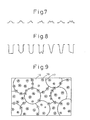
- Fig. 7 is an illustration schematically showing an example of the cross-sectional shape of "fine humps.”
- the "fine humps" shown in Fig. 7 are formed in such a manner as to be continuously connected to each other on the rims of the dimples, thereby giving "roundness" to the rims of the dimples.
- the dimple rims with "roundness” stated above act to delay the generation of solidification nuclei in molten steel contacting with the rims and thereby delay the solidification progress of the molten steel.
- the dimple rims with "roundness” described above act to accelerate the invasion of molten steel into the bottoms of the dimples. As a result, the molten steel easily contacts with the bottoms of the dimples under the static pressure of the molten steel and the screw-down force of the cooling drum.
- the sharp shapes disappear and slow-cooling parts that hold gas are formed.
- the dimple rims having the "fine holes” act to delay the generation of solidification nuclei in molten steel contacting with the rims and thereby delay the progress of solidification of the molten steel.
- Fig. 8 is an illustration schematically showing an example of the cross-sectional shape of the "fine holes.”
- the "fine humps,” “fine holes,” or “fine unevenness” formed on the bottom surface of dimples act to accelerate the generation of solidification nuclei in molten steel contacting with the surfaces, thereby accelerating the solidification of the molten steel.
- Figs. 9 and 10 are illustrations schematically showing appearances wherein "fine humps 18" are formed on the peripheral surface of a cooling drum
- Figs. 11 and 12 are illustrations schematically showing appearances wherein "fine holes 19" are formed on the peripheral surface of a cooling drum.
- a cooling drum for thin slab continuous casting of the present invention (hereunder referred to as “cooling drum of the present invention") secures sufficient “dimple depth” to suppress the generation of "pickling unevenness” and “pickling-unevenness accompanying cracks,” and moreover has the functions of delaying the solidification of molten steel at the rims of the dimples while accelerating the invasion of molten steel into the bottoms of the dimples, and accelerating the solidification of the molten steel invading and contacting with the surfaces at the bottom surfaces of the dimples.
- a cooling drum of the present invention even if scum is entrapped between the cooling drum and molten steel to delay the solidification of molten steel portions with scum deposited thereon and a solidifying shell formed is made thinner at the portions with scum deposited thereon, the degree of inequality of the solidifying shell thickness is limited to 20 % or less and therefore "strain" (causing "pickling-unevenness accompanying cracks"), that is generated and accumulated in unequal thickness portions of the solidifying shell, is reduced.
- dimples 40 to 200 ⁇ m in average depth and 0.5 to 3 mm in diameter of circle equivalent are formed adjacent to each other at the rims of the dimples on the peripheral surface of the cooling drum (see Fig. 6).
- the average depth of the dimple is less than 40 ⁇ m, a macroscopic stress/strain relaxation effect of the dimples cannot be obtained and therefore its lower limit is set at 40 ⁇ m.
- the average depth of the dimples is more than 200 ⁇ m, the invasion of molten steel into the bottoms of the dimples becomes insufficient, and therefore its upper limit is set at 200 ⁇ m.
- the size of the dimples is 0.5 to 3 mm in diameter of circle equivalent. If this diameter is less than 0.5 mm, the invasion of molten steel into the bottoms of the dimples becomes insufficient, and therefore its upper limit is set at 0.5 mm. On the other hand, if the diameter of circle equivalent is more than 3 mm, the accumulation of stress/strain on a dimple-by-dimple basis becomes large to make it easy to generate dimple cracks, and therefore its upper limit is set at 3 mm.
- Fine humps 1 to 50 ⁇ m in height and 5 to 200 ⁇ m in diameter of circle equivalent are formed on the surfaces of dimples of the shape stated above.
- the humps cannot make sufficient contact with molten steel to inhibit the generation of solidification nuclei and, therefore, its lower limit is set at 1 ⁇ m.
- the height is more than 50 ⁇ m, the solidification of molten steel is delayed at the bottoms of the humps to cause the inequality of a solidifying shell in the dimples and, therefore, its upper limit is set at 50 ⁇ m.
- the diameter of circle equivalent is less than 5 ⁇ m, cooling of the humps becomes insufficient to inhibit the generation of solidification nuclei and, therefore, its lower limit is set at 5 ⁇ m.
- the diameter of circle equivalent is more than 200 ⁇ m, molten steel portions insufficiently contacting with the humps are generated to make the generation of solidification nuclei unequal and, therefore, its upper limit is set at 200 ⁇ m.
- Fine holes 5 ⁇ m or more in depth and 5 to 200 ⁇ m in diameter of circle equivalent are formed on the surfaces of dimples of the shape stated above.
- the depth is less than 5 ⁇ m, the generation of air gaps at fine hole portions becomes insufficient and the generation of solidification nuclei on dimple surfaces excluding the fine hole portions cannot be reliably achieved and, therefore, its lower limit is set at 5 ⁇ m.
- the diameter of circle equivalent is less than 5 ⁇ m, a cooling relaxation effect at the fine hole portions cannot be sufficiently exerted and the generation of solidification nuclei can not be limited to dimple surfaces excluding the fine hole portions and, therefore, its lower limit is set at 5 ⁇ m.
- the diameter of circle equivalent is more than 200 ⁇ m, molten steel invades even into the fine hole portions, the molten steel having invaded thereinto solidifies to bind a solidifying shell, which causes strain to concentrate and accelerates the generation of cracks, and therefore its upper limit is set at 200 ⁇ m.
- Fine unevenness 1 to 50 ⁇ m in average depth and 10 to 200 ⁇ m in diameter of circle equivalent are formed on the surfaces of dimples of the shape stated above.
- the average depth is less than 1 ⁇ m, solidification nuclei are not generated at the unevenness portions, and therefore its lower limit is set at 1 ⁇ m.
- the average depth is more than 50 ⁇ m, solidification at the bottom portions of the unevenness is delayed to cause inequality of the solidifying shell in the dimples, and therefore its upper limit is set at 50 ⁇ m.
- the diameter of circle equivalent is less than 10 ⁇ m, solidification nuclei are not generated at the unevenness portions, and therefore its lower limit is set at 10 ⁇ m.
- the diameter of circle equivalent is more than 200 ⁇ m, some portions of molten steel do not make sufficient contact with the unevenness portions to cause inequality in the generation of solidification nuclei, and therefore its upper limit is set at 200 ⁇ m.
- the cooling drum of the present invention it is preferable to form fine humps of a required shape adjacent to each other on the rims of dimples to give "roundness" to the rims, or to form “ fine holes” of a required shape on the rims, the dimples being "40 to 200 ⁇ m in average depth and 0.5 to 3 mm in diameter of circle equivalent” and being formed adjacent to each other at the rims of the dimples on the peripheral surface of the cooling drum.
- the shapes required of them are now explained.
- Fine humps 1 to 50 ⁇ m in height and 30 to 200 ⁇ m in diameter of circle equivalent are formed adjacent to each other on the rims of dimples of the shape stated above.
- the height is less than 1 ⁇ m, the effect of delaying the generation of solidification nuclei at the rims of the dimples can not be obtained, and therefore its lower limit is set at 1 ⁇ m.
- the height is more than 50 ⁇ m, the invasion of molten steel into the bottoms of the dimples becomes insufficient, and therefore, its upper limit is set at 50 ⁇ m.
- the diameter of circle equivalent is less than 30 ⁇ m, the effect of delaying the generation of solidification nuclei at the rims of the dimples can not be obtained, and therefore its lower limit is set at 30 ⁇ m.
- the diameter of circle equivalent is more than 200 ⁇ m, the stress/strain relaxation effect of the dimples can not be obtained, and therefore its upper limit is set at 200 ⁇ m.
- Fine holes 5 ⁇ m or more in depth and 5 to 200 ⁇ m in diameter of circle equivalent are formed on the rims of dimples of the shape stated above.
- the depth is less than 5 ⁇ m, the formation of air gaps at the fine hole portions becomes insufficient and the effect of delaying the generation of solidification nuclei cannot be obtained, and therefore its lower limit is set at 5 ⁇ m.
- the diameter of circle equivalent is less than 5 ⁇ m, solidification nuclei are generated in the proximity of the rims other than the fine hole portions and the effect of accelerating the invasion of molten steel into the bottom portions of the dimples cannot be obtained and, therefore, its lower limit is set at 5 ⁇ m.
- the diameter of circle equivalent is more than 200 ⁇ m, the apparent height of the dimple rims is lowered and the effect of relaxing stress/strain cannot be obtained and, therefore, its upper limit is set at 200 ⁇ m.
- the peripheral surface structure of a cooling drum can be formed by appropriately combining the "fine humps,” “fine holes,” and “fine unevenness” of (a) to (e) stated above according to the kind of steel, a desired plate thickness, and quality.
- a cooling drum of the present invention can be used for both single-roll type continuous casting and twin-roll type continuous casting.
- a thin slab of the present invention is made basically in such a manner that molten steel starts to solidify from the originating points of solidification nuclei generated in molten steel portions contacting with the rims of the dimples on the peripheral surface of a cooling drum and then solidifies from the originating points of solidification nuclei generated in molten steel portions contacting with the fine humps, fine holes, or fine unevenness on the surfaces of the dimples stated above.
- the originating points of solidification nuclei in molten steel portions contacting with the rims of the dimples are generated along the rims, that is, in a ring shape of 0.5 to 3 mm in diameter of circle equivalent.
- the originating points of solidification nuclei generated in molten steel portions contacting with "fine humps,” “fine holes,” or “fine unevenness” on the surfaces of the dimples are generated at intervals of 250 ⁇ m or less.
- the "fine depressions” and/or “fine humps” described above and formed on the surface of the thin slab correspond to “fine holes” or “fine unevenness” in the event that they are formed on the rims of dimples on the peripheral surface of a cooling drum of the present invention.
- each of the regions partitioned by the "reticular connected depressions" is a region 0.5 to 3 mm in diameter of circle equivalent corresponding to the diameter of circle equivalent of the dimples.
- fine depressions and/or fine humps are formed by contacting with the fine humps, fine holes, or fine unevenness on the surfaces of the dimples on the peripheral surface of the cooling drum. It is preferable that these "fine depressions” and/or “fine humps” exist at intervals of 250 ⁇ m or less.
- a thin slab of the present invention is made in such a manner that molten steel starts to solidify from the originating points of solidification nuclei generated along the reticular connected depressions formed on molten steel portions contacting with the rims of the dimples on the peripheral surface of a cooling drum while maintaining the shape of the reticular connected depressions and then solidifies from the originating points of solidification nuclei generated in molten steel portions contacting with the "fine humps,” “fine holes,” or “fine unevenness” on the surfaces of the dimples described above.
- each of the regions partitioned by the reticular connected depressions is a region 0.5 to 3 mm in diameter of circle equivalent and/or the originating points of solidification nuclei generated in molten steel portions contacting with the fine humps, fine holes, or fine unevenness stated above are generated at intervals of 250 ⁇ m or less.
- the present invention is not restricted to the peripheral surface structures of cooling drums and the conditions of continuous casting used in the examples, and to the shapes/structures of thin slabs acquired by the peripheral surface structures and under the conditions of continuous casting.
- the rolled-in scale defects are preferentially generated in portions with higher transferred humps among the portions of transferred humps, that is, portions corresponding to deeper dimples among the dimples formed on the peripheral surface of the cooling drum.
- portions with higher transferred humps among the portions of transferred humps that is, portions corresponding to deeper dimples among the dimples formed on the peripheral surface of the cooling drum.
- Dimples formed on the peripheral surface of the cooling drum are worn away by extended casting and that causes a shorter service life of the cooling drum. It was found out that, in order to suppress the rolled-in scale defects caused by the transferred humps and the shorter service life caused by the wear of the dimples, dimples having a small difference between the maximum depth and the average depth were effective, and it was made clear that the range of dimple depth distribution could be smaller if the range (the maximum diameter - the minimum diameter) of grain diameter distribution of the shot was made smaller.
- Figs. 13 and 14 show the roughness of the surface obtained by forming dimples 2.1 mm in average diameter and 130 ⁇ m in average depth on the peripheral surface of a cooling drum using conventional shot blasting which is the most commonly used method, taking a replica of the dimples on the peripheral surface of the cooling drum, and then observing (photographing) the replica obliquely at an angle of 45° under a magnification of 15 times (Fig. 13) and 50 times (Fig. 14) with an electron microscope.
- the roughness of dimples is clear and the diameter of dimples reaches 4,000 ⁇ m and the depth thereof exceeds 100 ⁇ m.
- fast cooling portions and slow cooling portions exist in a mixed state when a solidifying shell is formed. This naturally causes an excessively slow cooling phenomenon to occur in the concavity of dimples formed on the peripheral surface of a cooling drum, and on the other hand, a fast cooling phenomenon to occur in the convexity thereof.
- the present inventors formed fine unevenness 10 to 50 ⁇ m in average diameter and 1 to 50 ⁇ m in average depth and fine humps 1 to 50 ⁇ m in height generated by the intrusion of alumina grit fragments on the peripheral surface of a cooling drum by forming dimples 1.0 to 4.0 mm in average diameter and 40 to 170 ⁇ m in average depth on the peripheral surface of the cooling drum and then by spraying very fine alumina grit of tens to hundreds of microns, in average diameter, on the dimples.
- fine unevenness and fine humps are formed additionally in the conventional dimples having large diameters and large depths.
- the fine unevenness are of 10 to 50 ⁇ m in average diameter and 1 to 50 ⁇ m in average depth and the fine humps are of 1 to 50 ⁇ m in height.
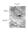
- Figs. 15, 16 and 17 show the results (surface ruggedness) of the observation in which a replica is taken from the dimples thus formed on the peripheral surface of the cooling drum, and then the replica is observed (photographed) obliquely at an angle of 45° under a magnification of 15 times (Fig. 15), 50 times (Fig. 16) and 100 times (Fig. 17) with an electron microscope.
- the state of the fine unevenness formed in the dimples can be seen in Figs. 15 (15 times) and 16 (50 times).
- a portion into which an alumina grit segment intrudes can be seen as indicated by an arrow.
- the distributions of fast cooling portions and slow cooling portions are narrowed and thus cooling can be more equalized when a solidifying shell is formed.
- alumina grit of tens to hundreds of ⁇ m is used to form fine unevenness of the size stated above. If the size of the alumina grit is less than tens of ⁇ m, the fine unevenness are hardly formed and grit fragments forming fine humps become too small to acquire the effect of forming humps. On the other hand, if the size is more than hundreds of ⁇ m, it exceeds the size (40 to 200 ⁇ m in average depth) of the previously formed dimples and grit fragments become excessively large. For this reason, the size of alumina grit used is set at tens to hundreds of ⁇ m. Preferably, the alumina grit is about 50 to 100 ⁇ m in size.
- the size of dimples formed by an ordinary shot blasting method, a photoetching method, laser material processing, or the like is enough for the size of dimples first formed according to the present invention, and it is preferable that the size is 1.0 to 4.0 mm in average diameter and 40 to 200 ⁇ m in average depth. Further it is preferable that the size of fine unevenness further formed by spraying alumina grit of tens to hundreds of ⁇ m on the surfaces of the dimples formed in such a size is 10 to 50 ⁇ m in average diameter and 1 to 50 ⁇ m in average depth, and moreover the size of fine unevenness is equal to or less than the average depth of ordinary dimples.
- Fine humps formed according to the present invention are of 1 to 50 ⁇ m in height.
- a plating method using a solution comprising one or more of Ni, Co, Co-Ni alloy, Co-W alloy, and Co-Ni-W alloy or a flame spraying method is also applicable.
- the solidification starting points of molten steel are dispersed more finely than in the case of ordinary dimples by further forming fine unevenness or fine humps formed by the intrusion of fine alumina grit fragments in the ordinary dimples formed by an ordinary method, and thus the generation of fine cracks on a slab during its cooling can be reliably prevented.
- casting was performed by using aforementioned cooling drums under an atmosphere of a non-oxidizing gas soluble in molten steel, or the mixture of a non-oxidizing gas soluble in molten steel and a non-oxidizing gas insoluble in molten steel, and the dimples of the cooling drums according to the present invention were transferred to the cast slab.
- dimples 1.5 to 3.0 mm in average diameter and 30 to 250 ⁇ m in average depth were formed as the base dimples on the peripheral surface of a copper-made cooling drum 1,000 mm in diameter by a conventional shot blasting method.
- the comparative examples were the cases of the cooling drums wherein: the base dimples were formed by a shot blasting method and applied as they were; the depth of base dimples was exceedingly small or large; or the diameter or depth of fine unevenness, even if they were formed, or the height of fine humps was outside the range specified by the present invention.
- fine unevenness 10 to 50 ⁇ m in average diameter and 1 to 50 ⁇ m in average depth were formed by additionally blasting alumina grit about 50 to 100 ⁇ m in size onto above-mentioned base dimples and simultaneously fine humps 1 to 50 ⁇ m in height were formed by intruding the fragments of above-mentioned alumina grit into the surface of the fine unevenness.
- the results are also shown in above-mentioned Table 4.
- Nos. 2 and 8 are the examples of the present invention, and the remaining Nos. 1, 3 to 7, 9 and 10 are all comparative examples. In Nos. 2 and 8 of the examples of the present invention, no cracks occurred on slab surface.
- the average depth of the base dimples was 250 ⁇ m and exceedingly large and, in combination with the influence of absence of fine unevenness and fine humps, slab cracks of 5.0 mm/m 2 occurred.
- the base dimples were excessively deep, and the effects of the fine unevenness and the fine humps were not exhibited. Therefore, slab cracks of 3.0 mm/m 2 occurred.
- dimples on the peripheral surface of a cooling drum have been formed by a processing means such as shot blasting, photoetching or laser material processing, having an average diameter of 1.0 to 4.0 mm, the maximum diameter of 1.5 to 7.0 mm, an average depth of 40 to 170 ⁇ m, and the maximum depth of 50 to 250 ⁇ m based on the long term research and actual operation results.
- a processing means such as shot blasting, photoetching or laser material processing
- slab cracks could be eliminated by: measuring surface ruggedness with a two-dimensional roughness gage after dimples were formed; approximating the incidence of the trapezoidal portions to the incidence of the area where the plateau of the ruggedness existed continuously over a distance of 2 mm or more; defining the incidence of said area as the defective waveform rate, and then controlling the defective waveform rate to 3 % or less, preferably to 2.5 % or less.
- the present inventors discovered that, for solving the problem, it was necessary to control the diameter of shot blasting grit, which conventionally varied in size, within the range of 1.5 to 2.5 mm when it was used for shot blasting, and to optimize the nozzle shape and the blasting pressure when shot blasting was applied.
- Figs. 18, 19 and 20 show some parts of the results of measuring the surface ruggedness of cooling drums, after dimples are formed, with a two-dimensional roughness gage.
- the incidence of the trapezoidal portions namely, the incidence of the area where the plateau of the ruggedness exists continuously over a distance of 2 mm or more, against the entire measured length of 180 mm accounts for 7.5 % in Fig. 18 and 4.2 % in Fig. 19. In these cases, fine cracks occurred on the cast slab. Encircled portions in Figs. 18 and 19 indicate defective waveforms.
- the aforementioned incidence of the trapezoidal portions is 1.1 %, and the occurrence of fine cracks on the cast slab was scarcely observed.
- measured length should be at least 50 mm, more preferably 100 mm or more.
- Solidification starting points of molten steel can be finely dispersed and fine cracks of cast slabs that occur during cooling can certainly be prevented by: using the aforementioned cooling drum according to the present invention; casting molten steel under an atmosphere of a non-oxidizing gas soluble in molten steel, or the mixture of a non-oxidizing gas soluble in molten steel and a non-oxidizing gas insoluble in molten steel; and transferring the dimples of the cooling drum formed according to the present invention to the surface of the cast slab.
- examples of Nos. 3, 4 and 8 are of the present invention, and the remaining Nos. 1, 2, 5 to 7, 9 and 10 are all comparative examples.
- the slab cracks were not observed at all.
- the defective waveform rate was as high as 7.5 % and 4.2 % respectively, and therefore, slab cracks having crack incidence of 0.5 mm/m 2 and 0.2 mm/m 2 respectively occurred.
- the defective waveform rate was as high as 4.2 % and 4.5 % respectively, and for that reason, slab cracks having crack incidence of 17.0 mm/m 2 and 0.3 mm/m 2 respectively occurred.
- the defective waveform rate was 4.5 % and 2.2 % respectively, and slab cracks having crack incidence of 5.0 mm/m 2 and 3.0 mm/m 2 respectively occurred. This was because the base dimples were exceedingly deep and therefore cracks, caused by uneven cooling, developed within each dimple.
- Aforementioned cooling drum for thin slab continuous casting according to the present invention (hereinafter referred to as a "cooling drum according to the present invention") is based on the fundamental technical thought that dimples 40 to 200 ⁇ m in average depth and 0.5 to 3 mm in diameter of circle equivalent are formed adjacent to each other at the rims of the dimples on the plated peripheral surface of the drum and a film containing a substance more excellent than Ni in the wettability with scum is formed on said peripheral surface.
- a plated layer of Ni which has lower thermal conductivity than Cu and is hard and excellent in resistance to thermal stress, and it is preferable that said plated layer contains any one or more of the elements more prone to oxidize than Ni, for example, W, Co, Fe or Cr.
- a film containing a substance more excellent than Ni in wettability with scum is further formed on the surface of the drum to improve the wettability with scum, while maintaining the slow cooling effect and the service life prolonging effect at the drum surface.
- oxides of the elements composing molten steel to be continuously cast are preferred as a substance more excellent than Ni in the wettability with scum.
- a film containing a substance more excellent than Ni in wettability with scum may be either a film of oxides of the elements composing molten steel coated on the plated peripheral surface of the cooling drum by means of spraying, roll coating or the like, or a film formed by the deposition of oxides generated by the oxidization of the composition elements of molten steel on the plated peripheral surface of the cooling drum during operation.
- above-mentioned substance more excellent than Ni in the wettability with scum may be the oxides of the elements composing the plated layer on the peripheral surface of the cooling drum. This is because the oxides generated by the oxidation of the plated layer on the peripheral surface of the cooling drum by the heat of molten steel are more excellent than said plated layer in the wettability with scum.
- dimples 40 to 200 ⁇ m in average depth and 0.5 to 3 mm in diameter of circle equivalent are formed adjacent to each other at the rims of the dimples.
- the average depth of dimples is limited to 40 to 200 ⁇ m. If the average depth is less than 40 ⁇ m, a macroscopic stress/strain relaxation effect can not be obtained, and therefore the lower limit is set at 40 ⁇ m. On the other hand, if the average depth exceeds 200 ⁇ m, the penetration of molten steel to the bottom of the dimples becomes insufficient and the unevenness of the dimples increases and, therefore, the upper limit is set at 200 ⁇ m.
- the size of the dimples is limited to 0.5 to 3 mm in diameter of circle equivalent. If the diameter is less than 0.5 mm, the penetration of molten steel to the bottom of the dimples becomes insufficient and the unevenness of the dimples increases, and therefore the lower limit is set at 0.5 mm. On the other hand, if the diameter of circle equivalent exceeds 3 mm, the accumulation of stress and strain within each dimple increases and the dimples become more susceptible to cracks, and therefore the upper limit is set at 3 mm.
- the dimples of above-mentioned shape are formed so as to adjoin each other at the rims of the dimples.
- Each of the dimples thus formed can disperse the stress and strain exerted on a solidified shell, and it becomes possible to reduce the macroscopic stress and strain exerted on a solidified shell.
- FIG. 6 A formed pattern of above-mentioned dimples is shown in Fig. 6.
- fine humps 1 to 50 ⁇ m in height and 5 to 200 ⁇ m in diameter of circle equivalent on the surfaces of the dimples of aforementioned dimension. These fine humps can promote the solidification of molten steel contacting with the surfaces of the dimples.
- the height of the fine humps is less than 1 ⁇ m, the humps are unable to contact with molten steel sufficiently, solidification nuclei are not generated and the solidification of molten steel cannot be promoted and, therefore, the lower limit is set at 1 ⁇ m.
- the height exceeds 50 ⁇ m the solidification of molten steel at the bottom of the humps is delayed and the unevenness of solidified shell is developed within a dimple and, therefore, the upper limit is set at 50 ⁇ m.
- the diameter of circle equivalent is less than 5 ⁇ m, cooling at the humps becomes insufficient and solidification nuclei are not generated, and therefore the lower limit is set at 5 ⁇ m.
- the diameter of circle equivalent exceeds 200 ⁇ m, the portions of molten steel insufficiently contacting with the humps appear and the generation of solidification nuclei becomes uneven, and therefore the upper limit is set at 200 ⁇ m.
- the above-mentioned fine humps are coated with a film containing a substance more excellent than Ni in wettability with scum.
- above-mentioned fine humps coated with a film containing a substance more excellent than Ni in wettability with scum may be fine humps on which oxides generated by the oxidization of the elements composing molten steel are deposited.
- the deposition of the oxides generated by the oxidization of the elements composing molten steel on above-mentioned fine humps enhances the wettability of the fine humps with scum, promotes the generation of greater amount of starting points of solidification nuclei at the contact portions of molten steel with said fine humps, and expedites the solidification of molten steel.
- the rims of the as-formed dimples have sharp shapes, it is possible to furnish said rims with "roundness" by forming a number of above-mentioned fine humps in such a manner that they exist adjacent to each other. By this "roundness,” the generation of solidification nuclei is delayed in the molten steel contacting with the rims of the dimples, and the progress of solidification becomes slow. Further, the rims of the dimples with above-mentioned roundness serve to promote the penetration of molten steel into the concavities of the dimples. As a result, molten steel can reach and contact with the bottom of the dimples more easily under a static pressure of the molten steel and the screw-down force of the cooling drum.
- the height of the fine humps is less than 1 ⁇ m, the effect of delaying the generation of solidification nuclei at the rims of the dimples is not obtained, and therefore the lower limit is set at 1 ⁇ m.
- the upper limit is set at 50 ⁇ m.
- the diameter of circle equivalent is less than 30 ⁇ m, the effect of delaying the generation of solidification nuclei at the rims of the dimples is not obtained, and therefore the lower limit is set at 30 ⁇ m.
- the diameter of circle equivalent exceeds 200 ⁇ m, the stress/strain relaxation effect of the dimples themselves is not obtained and, therefore, the upper limit is set at 200 ⁇ m.
- the rims of the dimples with the "fine holes” serve to delay the generation of the solidification nuclei in the molten steel contacting with said rims, and to delay the progress of solidification.
- the rims of the dimples with the "fine holes” serve to promote the penetration of molten steel into the concavities of the dimples. As a result, molten steel can reach and contact the bottom of the dimples more easily under a static pressure of the molten steel and the screw-down force of the cooling drum.
- the lower limit is set at 5 ⁇ m.
- the diameter of circle equivalent is less than 5 ⁇ m, solidification nuclei are generated in the vicinities of the rims except the fine hole portions, and the effect of promoting the penetration of molten steel to the bottom of the dimples is not obtained and, therefore, the lower limit is set at 5 ⁇ m.
- the diameter of circle equivalent exceeds 200 ⁇ m, the apparent height of the rims of the dimples becomes lower and the stress/strain relaxation effect is not obtained and, therefore, the upper limit is set at 200 ⁇ m .
- a cooling drum In a cooling drum according to the present invention, it is possible to form the peripheral surface configuration as appropriate according to steel grade, prescribed thickness and quality by combining aforementioned fine humps and fine holes properly. What characterizes it most is forming a film containing a substance more excellent than Ni in wettability with scum on said peripheral surface.
- a cooling drum according to the present invention is a cooling drum which has been improved, from the viewpoints of the peripheral surface configuration and the peripheral surface material, in order to suppress both of the occurrence of "dimple cracks” and the occurrence of "pickling unevenness” and “pickling-unevenness accompanying cracks,” and to produce high quality thin slabs and final sheet products with higher yields.
- a cooling drum according to the present invention is applicable to either a single drum type continuous caster or a twin drum type continuous caster.
- SUS304 stainless steels were cast into strip-shaped thin slabs of 3 mm in thickness by a twin drum type continuous caster, and the slabs were cold-rolled to produce sheet products of 0.5 mm in thickness.
- the outer cylinder 1,330 mm in width and 1,200 mm in diameter of a cooling drum was copper-made, a Ni plated layer of 1 mm in thickness was coated on the peripheral surface of the outer cylinder, and then a coating layer shown in Table 6 was formed thereon.
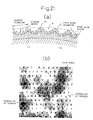
- Fig. 21 includes: (a) a sectional view showing the peripheral surface layer of a cooling drum according to the present invention in an enlarged state; and (b) a plan view showing the ruggedness of the surface with the depth of the color.
- the constituent requirements of a cooling drum according to the present invention and the reasons specifying them will be explained hereunder in detail based on Fig. 21.
- the base material 20 of a drum is required to have a thermal conductivity of 100 W/m ⁇ K or more for maintaining the temperature of the drum low, suppressing the generation of thermal stress, and prolonging the service life. Since the thermal conductivity of copper or copper alloy is 320 to 400 W/m ⁇ K, the copper or copper alloy is most suited to a drum base material.
- the Vickers hardness Hv of an intermediate layer 21 is less than 150, deformation resistance required of the intermediate layer 21 is not as good and the service life becomes short. On the other hand, if the Hv exceeds 1,000, toughness becomes low and cracks tend to occur, and therefore it is desired that the Hv of the intermediate layer 21 is less than 1,000.
- the thickness of an intermediate layer 21 is required to be 100 ⁇ m or more to protect the drum base material 20 thermally, but the maximum thickness thereof is required to be 2,000 ⁇ m as a condition to avoid the excessive rise of the surface temperature of the intermediate layer 21.
- a material constituting an intermediate layer 21 Ni, Ni-Co, Ni-Co-W, Ni-Fe and the like, which have a thermal conductivity of about 80 W/m ⁇ K and a capability of keeping the temperature of the drum base material 20 low, are appropriate, and the coating by the plating can stabilize the bonding strength, improve the strength and prolong the service life. Further, the plating is also desirable from the viewpoint of forming a uniform coating.
- the most important material property that is required of the outermost surface 22 of the drum is abrasion resistance.
- the practically required minimum Vickers hardness Hv is 200.
- Sufficient abrasion resistance is secured if the thickness is 1 ⁇ m or more. Since a hard plated layer material has a low thermal conductivity in general, the thickness must be 500 ⁇ m or less to control the surface temperature so as not to rise exceedingly.
- Ruggedness of a long cycle in the order of 1 mm is formed on the entire peripheral surface layer of a cooling drum by shot blasting method or the like.
- the molten steel comes in contact with the convexities of the dimples at first, and then the generation of solidification nuclei takes place, while in the mean time, in the concavities of the dimples, gas gaps are formed between the surface of the cast slab and the surface of the dimples, and the generation of solidification nuclei is delayed.
- the solidification-contraction stress is dispersed and relaxed by the generation of solidification nuclei at the convexities of the dimples and, therefore, the occurrence of cracks, is suppressed.
- the diameter of the dimples is specified in relation to the occurrence of cracks attributed to the solidification-contraction stress brought forth by the delayed solidification in the concavities of the dimples, and is required to be 2,000 ⁇ m or less. Further, the lower limit of the diameter is specified in relation to the diameter of the fine holes (fine holes) 19 hereinafter referred to, and as a diameter larger than that of the fine holes (fine holes) is required, the lower limit is set at 200 ⁇ m.
- the depth of the dimples is required to be 80 ⁇ m or more for forming aforementioned gas gaps.
- the depth of the dimples is required to be 200 ⁇ m or less. Cracks and uneven luster on a thin slab C can be effectively suppressed under a steady casting condition by forming the dimples as explained above.
- the present inventors carried out experimental research in detail, and, as a result, made clear that the unevenness of the solidification was not generated even at the portions where scum was carried in by further forming fine holes (fine holes) on the dimples under a specific condition.
- the present inventors discovered that the unevenness of solidification that occurred when scum flowed in between molten steel and a cooling drum was not caused by the difference between the thermal conductivity of scum and that of molten steel, but was caused by the presence of air layers formed with the entanglement of air when the scum flowed in.
- fine holes fine holes which are fine enough to the extent where the inflow of molten steel and scum is hindered by their surface tensions exist on the surface, the above-mentioned air is aggregated at the portions of the fine holes (fine holes), and air layers are not formed.
- the upper limit of the diameter of the hole is required to be 200 ⁇ m so as not to allow the inflow of molten steel and scum. Further, as a requisite to effectively aggregate air in the fine holes when the air is entangled, the minimum diameter of the holes is specified to be 50 ⁇ m.
- the holes are required not to contact with each other for aggregating air effectively and, in order to secure the generation of solidification nuclei, the center to center pitch of the holes is required to be 100 to 500 ⁇ m. Further, in order to exhibit the air aggregating function effectively and to specify the generation of solidification nuclei clearly, the depth of fine holes is required to be 30 ⁇ m or more or, more preferably, 50 ⁇ m or more.
- the dimples and fine holes as mentioned above are formed by forming an intermediate layer 21 and an outermost surface 22 on a cooling drum, applying plating treatment on the outermost surface 22, and then applying, for instance, shot blasting followed by laser material processing.
- the hardness of the plated layer of the outermost surface is very high and there is a possibility of the generation of cracks in the plated layer during the dimple forming, it is possible as well to form dimples, for instance, by shot blasting after forming the intermediate layer 21 by plating, and then to form the outermost surface 22 thereon, and finally to form the fine holes 19.
- dimples 16 for instance, by shot blasting after forming an intermediate layer 21 by plating on a drum base material, then to form fine holes 19 by laser material processing, and then to form an outermost surface 22 by applying hard plating.
- the order of forming the outermost surface can be selected as appropriate according to the choice of a plated material.
- a means to form these dimples 16 and fine holes 19 will be explained hereunder.
- a shot blasting method that can three-dimensionally form a random distribution pattern of dimples is effective as a method of forming dimples overlapping each other.
- any other processing means including electric discharge machining and the like may be used as long as the means can perform a processing that satisfies the conditions specified by the present invention.
- a means of forming fine holes a pulsed laser processing method that can easily perform the pattern control three-dimensionally is most appropriate.
- a cooling drum is manufactured and used according to the conditions specified by the present invention before being used for thin slab casting.
- a plated layer material of the outermost surface which has a possibility of the fine holes being abraded along with the progress of casting is selected, it is also possible, as shown in Fig. 23, to employ a means of continuously forming fine holes on a cooling drum, during casting, by pulsed laser processing at a certain position after the drum surface leaves the molten steel.
- Austenitic stainless steels (SUS304) were cast into strip-shaped thin slabs of 3 mm in thickness by a twin drum type continuous caster shown in Fig. 1 and then the slabs were hot-rolled and cold-rolled to produce sheet products of 0.5 mm in thickness.
- used were the cooling drums 800 mm in width and 1,200 mm in diameter on the peripheral surfaces of which intermediate layers and outermost surface layers were plated and dimples and fine holes were formed on the conditions shown in Table 7.
- a shot blasting method was used to form the dimples, and a laser material processing method was used to form the fine holes.
- the durability of a cooling drum was evaluated by visually observing the state of abrasion of the peripheral surface layer d after 20 castings had been carried out. Further, the quality of a cast slab was evaluated by visually inspecting the sheet products after cold-rolling.
- Nos. 1 to 8 are the examples according to the present invention.
- Nos. 9 and 10 are the comparative examples according to a conventional method in the cases with and without fine holes formed on the Ni-plated drum surface.
- the present inventors carried out experimental research in detail and, as a result, made clear that the unevenness of the solidification was not generated even at the portions where scum was carried in by forming fine holes (fine holes) on the dimples under a specific condition.
- the present inventors discovered that the unevenness of solidification that occurred when scum flowed in between molten steel and a cooling drum was not caused by the difference between the thermal conductivity of scum and that of molten steel, but was caused by the presence of air layers formed with the entanglement of air when the scum flowed in. That is, during casting, if fine holes, which are fine enough to the extent where the inflow of molten steel and scum is hindered by their surface tensions, exist on the surface, above-mentioned air is aggregated at the portions of the holes, and air layers are not formed.
- the upper limit of the diameter of the hole is required to be 200 ⁇ m so as not to allow the inflow of molten steel and scum. Further, as a requisite to effectively aggregate air in the fine holes when the air is entangled, the minimum diameter of the holes is specified to be 50 ⁇ m.
- the center to center pitch of the holes is required to be 100 to 500 ⁇ m.
- the depth of fine holes is required to be 50 ⁇ m or more.
- Requisites for forming the dimples of this kind will be explained in detail hereunder.
- Roughness (dimples) of a long cycle in the order of 1 mm is formed on the entire peripheral surface layer of a cooling drum by shot blasting method or the like.
- the molten steel comes in contact with the convexities of the dimples at first, and then the generation of solidification nuclei takes place while, in the meantime, in the concavities of the dimples, gas gaps are formed between the surface of the cast slab and the surface of the dimples, and the generation of solidification nuclei is delayed.
- the solidification-contraction stress is dispersed and relaxed by the generation of solidification nuclei at the convexities of the dimples, and therefore the occurrence of cracks is suppressed.
- the diameter of the dimples is specified in relation to the occurrence of cracks attributed to the solidification-contraction stress brought forth by the delayed solidification in the concavities of the dimples, and is required to be 3,000 ⁇ m or less.
- the lower limit of the diameter is specified in relation to the diameter of the fine holes, and since the diameter larger than that of the fine holes is required, the lower limit is set at 200 ⁇ m.
- the depth of the dimples is required to be 80 ⁇ m or more for forming aforementioned gas gaps.
- the depth of the dimples is required to be 250 ⁇ m or less.
- the material for the surface layer is required to have excellent thermal fatigue resistance and abrasion resistance.
- Surface hardness can be selected and used as a representative parameter in realizing these characteristics, and in this case, the Vickers hardness is required to be 200 and more.
- Any one of Ni, Ni-Co, Ni-Co-W, Ni-Fe, Ni-W, Co, Ni-Al and Cr can be selected as a material satisfying the requisites.
- thin film plating can be provided before or after forming fine holes by laser material processing, either of which may be selected as appropriate by comparing the laser material processing capability and the surface abrasion resistance.
- Fig. 26 shows a typical waveform of Q-switched CO 2 pulsed laser beam formed by a rotary chopper Q-switching method.
- N 2 having a high energy level relatively close to that of CO 2 among molecular oscillation levels is added to the laser medium to improve the oscillation efficiency.
- the Q-switched CO 2 pulsed laser beam takes a waveform of an "initial spike portion" corresponding to the giant pulse of a solid laser, followed by a "pulse tail portion” that oscillates like a continuous wave caused by the shift of collision energy from N 2 molecules to CO 2 molecules.
- the present inventors disclosed, for instance, in Japanese Unexamined Patent Publication No. H8-309571 that, when Q-switched CO 2 pulsed laser light was applied for forming holes, this pulse tail portion could contribute to forming them effectively.
- the forming of holes 10 to 50 ⁇ m in depth was the primary concern, and it was found that the forming of holes 50 ⁇ m or more in depth which was a target of the present invention could not be realized. More concretely, it was found that even if pulse energy was increased to a total time span of 20 ⁇ seconds, the increase of hole depth became saturated, and holes 50 ⁇ m or more in depth could not be formed.
- Fig. 27(a) shows the summarized result by taking pulse total time span on X-axis, formed hole depth on Y-axis, and pulse energy as the parameter, and (b) of the same figure shows the result summarized in a similar manner with regard to the diameter of the holes formed on the surface.
- the present inventors found that, if the pulse total width was changed under the pulse energy condition of 50 mJ or more, the pulse total width that had above-mentioned rim shifted towards the longer pulse total width side.
- pulse energy contained in the pulse tail portion increases proportionally, and as a result, the rate of increase of output at the rim of the initial spike portion is reduced from the level under the above-mentioned condition.
- a great increase of free electron density in the plasma produced by the laser is suppressed, and therefore the influence of the inverse damping radiation is reduced and hole depth increases monotonously along with the increase of pulse energy.
- the pulse total width can be changed by changing the slit opening time span in the Q-switching method using a rotary chopper.
- a pulse width as appropriate when changing the condition for forming fine holes (fine holes)
- a plurality of rotary chopper blades having different slit widths may be prepared, but it is also possible to realize various pulse total widths with single blade if a chopper blade having slits S of which the opening width varies in the radial direction, as shown in Fig. 25, is prepared.
- Fig. 28 is a graph showing a relation between pulse energy and hole depth with regard to the data obtained out of Fig. 27 (a) under the condition of the pulse total width of 30 ⁇ seconds.
- pulse energy is required to be more than 40 mJ to obtain holes 50 ⁇ m or more in depth which is an object of the present invention.
- pulse energy output can be controlled by varying the glow discharge electric energy at the time of discharge excitation.
- direct current discharge is generally used as a discharge excitation method, any other methods of continuously impressing an alternating current discharge and an RF discharge, and applying pulse modulation to the discharges, may be used.
- Fig. 24 is a drawing showing the configuration of a laser processing apparatus employed in the present invention.
- the laser oscillator 23 is a Q-switched CO 2 laser apparatus incorporating a Q-switching apparatus behind a continuous discharge excitation laser tube having carbon dioxide gas as oscillation medium.
- the Q-switching apparatus consists of a confocal telescope (which consists of a telescope condenser 26 and a total reflection mirror 27) and a rotary chopper 28 (refer to Fig. 25) installed at the confocal point.
- the number of revolutions of the rotary chopper 28 is 8,000 rpm, 45 slits (refer to S in Fig. 25) are formed on the chopper blade, and a series of pulses having 32 ⁇ sec. of pulse total width and 6 kHz of pulse repetition frequency are obtained.
- a collimating mirror a concave mirror
- the beam After the divergence angle of the laser beam L output by the laser oscillator 23 is corrected by a collimating mirror (a concave mirror) 29, the beam reaches a processing head 31, is condensed to a diameter of 100 ⁇ m by a ZnSe-made condenser 32 having a focal distance of 63.5 mm, and then is irradiated onto a cooling drum 1.
- a height copying sensor 36 of eddy-current type measures the distance between the processing head and the drum surface and, based on the result of the measurement, a Z-axis direction driving apparatus 35 moves the processing head so as to control the distance between the condenser 32 and the surface of the cooling drum 1 to a constant amount.
- a cooling drum 1 coated with Ni-Co-W plating and having dimples formed in advance by shot blasting was processed with laser pulse energy of 90 mJ.
- fine holes 180 ⁇ m in surface hole diameter and 55 ⁇ m in depth with a fine hole pitch of 250 ⁇ m were formed.
- a surface appearance of the cooling drum subjected to the processing is shown in Fig. 29.
- Austenitic stainless steels (SUS304) were cast into strip-shaped thin slabs of 3 mm in thickness by a twin drum type continuous caster shown in Fig. 1, employing the cooling drums processed according to above-mentioned method, and after the casting, the slabs were hot-rolled and then cold-rolled to produce sheet products of 0.5 mm in thickness.
- the quality of the cast slabs was evaluated by visually inspecting the sheet products after cold-rolling. As a result, it was observed that thin slabs were free of surface cracks, and sheet products after rolling were free of surface defects and unevenness.
- FIG. 30 is an illustration of a side view showing the process of forming a hole on a metallic material with a pulsed laser beam.
- a coating material 38 consisting of oils and fats is coated on the surface of a metallic material which is a to-be-processed work piece 37 (a cooling drum, for instance) beforehand.
- a laser beam 39 is condensed by a condenser not indicated in the figure so as to be focused on the surface of the metallic material 37, and irradiated.
- the laser beam 39 reaches the surface of the metallic material 37 after being refracted at the interface of air and the coated material 38 and subjected to a certain absorption.
- a sublimation phenomenon takes place on the surface of the metallic material 37 caused by high momentary energy density of the laser beam 39, and thus a hole is formed.
- a surface 41 of a molten phase, and an interface 40 between the molten phase and a solid phase are formed at the bottom of the hole, and part of the molten phase which exists between both interface (41 and 40) is discharged outward as sputter 42 by a force overcoming the surface tension exerted by the reaction force of the evaporation of the metallic material 37 and the back pressure of the assist gas.
- Constituent portions of the sputter 42 having momentum only enough to allow them to stay in the vicinity of the hole reach the surface of the work piece being processed in molten state, and are deposited on the surface and become dross if a coating material is not applied.
- the present inventors carried out experimental research to clarify whether the above-mentioned principle was applicable to any kind of oils and fats. As a result, the present inventors discovered that the effect of suppressing the deposition of dross varied greatly depending on the kinds of oils and fats and the thickness of the coating. As a result of investigating the outcome of the experiment systematically, it was found that the difference in the phenomenon could be summarized by the transmittance of the laser light in the thickness direction of the coating medium.
- Absorption of pulse energy by plasma reduces energy reaching the surface of a metallic material which is a work piece to be processed and, simultaneously, plasma itself becomes a secondary heat source. Since the plasma rapidly expands as time elapses, the size of the secondary heat source is extraordinarily larger than the condensed diameter of the laser beam.
- portions having small amount of momentum of the sputter produced according to the process as explained in Fig. 30 are reheated by the plasma, and that leads to increasing the amount of dross deposited in the vicinity of the hole.
- the light transmittance T is less than 0.5, namely, if absorption at coated material is exceedingly large, the aforementioned phenomenon takes place and the dross suppressing effect is deteriorated. Then, if the absorption coefficient ⁇ does not satisfy the expression (3), the dross suppressing effect is deteriorated similarly even if light transmittance T is 0.5 or more.
- oils and fats to be coated are not specifically defined in the above explanation, petroleum lubricants exhibit a most appropriate effect. However, any kind of oils and fats can be selected as long as it satisfies the expressions (2) and (3).
- Fig. 31 shows the results of measuring the infrared spectroscopy transmittance property of a petroleum lubricant of class 3 used for the examples of the present invention; (a) shows the result in the case of lubricant thickness of 15 ⁇ m, and (b) shows the result in the case of lubricant thickness of 50 ⁇ m.
- the results of the measurement include 7.5 % of transmittance loss at the window since KBr single crystal is used as the gate material.
- Fig. 32 is a graph showing the light transmittance of the above-mentioned coating material itself expressed as a function of lubricant thickness after obtaining said light transmittance by evaluating the transmittance property at various thickness as shown in Fig. 31, and correcting the results for the transmittance of the window material.
- the absorption coefficient ⁇ of the lubricant is 4.05 mm -1 .
- Pulse energy was set at 90 mJ
- condensed diameter of the pulsed laser beam was set at 95 ⁇ m
- air was supplied as the assist gas coaxially with the laser beam at a flow rate of 20 liter/minute.
- a pulsed Q-switched CO 2 laser is used as the laser light source for forming holes
- other laser sources by specifying the transmittance property of the coating material in relation to the laser wavelength to the range of the present invention.
- a YAG laser wavelength: 1.06 ⁇ m
- a semiconductor laser wavelength: about 0.8 ⁇ m
- an excimer laser wavelength: ultraviolet region
- a thin slab which does not have surface defects such as surface cracks and crevices, pickling unevenness, and pickling-unevenness accompanying cracks can be produced efficiently.
- the present invention can provide a high quality stainless steel sheet excellent in surface appearance and not having an uneven luster with a good yield and at a low cost, and greatly contributes to the development of the consumer goods manufacturing industry and the construction industry, wherein stainless steels are used as materials for products and construction materials.
Applications Claiming Priority (15)
| Application Number | Priority Date | Filing Date | Title |
|---|---|---|---|
| JP2000140315A JP3684136B2 (ja) | 2000-05-12 | 2000-05-12 | 薄鋳片連続鋳造機用ドラムおよび薄鋳片連続鋳造方法 |
| JP2000140315 | 2000-05-12 | ||
| JP2000175850 | 2000-06-12 | ||
| JP2000175850A JP2001353559A (ja) | 2000-06-12 | 2000-06-12 | 双ドラム式連続鋳造装置用冷却ドラムおよび連続鋳造方法 |
| JP2000288425 | 2000-09-22 | ||
| JP2000288425A JP3422979B2 (ja) | 2000-09-22 | 2000-09-22 | 薄鋳片連続鋳造機用ドラムのディンプル加工方法および装置 |
| JP2000306764A JP3908902B2 (ja) | 2000-10-05 | 2000-10-05 | 薄肉鋳片連続鋳造用冷却ドラム及び薄肉鋳片の連続鋳造方法 |
| JP2000306753 | 2000-10-05 | ||
| JP2000306711A JP3908901B2 (ja) | 2000-10-05 | 2000-10-05 | 薄肉鋳片連続鋳造用冷却ドラム及び薄肉鋳片とその連続鋳造方法 |
| JP2000306764 | 2000-10-05 | ||
| JP2000306711 | 2000-10-05 | ||
| JP2000306753A JP4406164B2 (ja) | 2000-10-05 | 2000-10-05 | 双ドラム式連続鋳造装置用冷却ドラムとそれを用いた鋳造方法 |
| JP2001073101A JP3796125B2 (ja) | 2001-02-08 | 2001-02-08 | 金属材料のレーザ穴加工方法 |
| JP2001073101 | 2001-02-08 | ||
| EP01930090A EP1281458B1 (fr) | 2000-05-12 | 2001-05-11 | Tambour de refroidissement pour le moulage par coulage continu de pieces fines et procede de moulage par coulage continu |
Related Parent Applications (1)
| Application Number | Title | Priority Date | Filing Date |
|---|---|---|---|
| EP01930090A Division EP1281458B1 (fr) | 2000-05-12 | 2001-05-11 | Tambour de refroidissement pour le moulage par coulage continu de pieces fines et procede de moulage par coulage continu |
Publications (2)
| Publication Number | Publication Date |
|---|---|
| EP1595621A1 true EP1595621A1 (fr) | 2005-11-16 |
| EP1595621B1 EP1595621B1 (fr) | 2009-10-28 |
Family
ID=27566974
Family Applications (5)
| Application Number | Title | Priority Date | Filing Date |
|---|---|---|---|
| EP05006814A Withdrawn EP1582279A1 (fr) | 2000-05-12 | 2001-05-11 | Bande mince coulée en continu |
| EP05006811A Expired - Lifetime EP1595621B1 (fr) | 2000-05-12 | 2001-05-11 | Tambour de refroidissement pour le moulage par coulage en continu de pieces fines |
| EP05006813A Withdrawn EP1595622A1 (fr) | 2000-05-12 | 2001-05-11 | Procédé de traitement d'un tambour de refroidissement pour la coulée en continu de bandet et apparatus correspondant |
| EP05006812A Expired - Lifetime EP1602424B2 (fr) | 2000-05-12 | 2001-05-11 | Tambour de refroidissement pour le moulage par coulage en continu de pieces fines et procede de coulage en continu |
| EP01930090A Expired - Lifetime EP1281458B1 (fr) | 2000-05-12 | 2001-05-11 | Tambour de refroidissement pour le moulage par coulage continu de pieces fines et procede de moulage par coulage continu |
Family Applications Before (1)
| Application Number | Title | Priority Date | Filing Date |
|---|---|---|---|
| EP05006814A Withdrawn EP1582279A1 (fr) | 2000-05-12 | 2001-05-11 | Bande mince coulée en continu |
Family Applications After (3)
| Application Number | Title | Priority Date | Filing Date |
|---|---|---|---|
| EP05006813A Withdrawn EP1595622A1 (fr) | 2000-05-12 | 2001-05-11 | Procédé de traitement d'un tambour de refroidissement pour la coulée en continu de bandet et apparatus correspondant |
| EP05006812A Expired - Lifetime EP1602424B2 (fr) | 2000-05-12 | 2001-05-11 | Tambour de refroidissement pour le moulage par coulage en continu de pieces fines et procede de coulage en continu |
| EP01930090A Expired - Lifetime EP1281458B1 (fr) | 2000-05-12 | 2001-05-11 | Tambour de refroidissement pour le moulage par coulage continu de pieces fines et procede de moulage par coulage continu |
Country Status (9)
| Country | Link |
|---|---|
| US (2) | US6896033B2 (fr) |
| EP (5) | EP1582279A1 (fr) |
| KR (3) | KR100668126B1 (fr) |
| AT (3) | ATE375833T1 (fr) |
| AU (1) | AU777752B2 (fr) |
| CA (1) | CA2377876C (fr) |
| DE (3) | DE60128217T2 (fr) |
| ES (3) | ES2287125T3 (fr) |
| WO (1) | WO2001085369A1 (fr) |
Families Citing this family (30)
| Publication number | Priority date | Publication date | Assignee | Title |
|---|---|---|---|---|
| US7073565B2 (en) * | 1999-02-05 | 2006-07-11 | Castrip, Llc | Casting steel strip |
| DE60128217T2 (de) * | 2000-05-12 | 2008-01-03 | Nippon Steel Corp. | Gekühlte giesswalze zum kontinuierlichen stranggiessen von dünnen produkten und kontinuierlichesstranggiessverfahren |
| AT412072B (de) | 2002-10-15 | 2004-09-27 | Voest Alpine Ind Anlagen | Verfahren zur kontinuierlichen herstellung eines dünnen stahlbandes |
| FR2855992B1 (fr) * | 2003-06-10 | 2005-12-16 | Usinor | Procede et installation de coule continue directe d'une bande metallique |
| US8312917B2 (en) * | 2004-12-13 | 2012-11-20 | Nucor Corporation | Method and apparatus for controlling the formation of crocodile skin surface roughness on thin cast strip |
| US7891407B2 (en) * | 2004-12-13 | 2011-02-22 | Nucor Corporation | Method and apparatus for localized control of heat flux in thin cast strip |
| US20060124271A1 (en) * | 2004-12-13 | 2006-06-15 | Mark Schlichting | Method of controlling the formation of crocodile skin surface roughness on thin cast strip |
| CA2597100C (fr) * | 2005-03-10 | 2013-01-22 | Sms Demag Ag | Procede de production d'une coquille pour la coulee continue et coquille pour la coulee continue |
| CH698238B1 (de) * | 2005-07-07 | 2009-06-30 | Main Man Inspiration Ag | Vorrichtung zur kontinuierlichen Oberflächenreinigung einer drehbeweglichen Giessrolle einer Bandgiessmaschine. |
| DE102006011384B4 (de) * | 2006-03-09 | 2019-09-05 | Sms Group Gmbh | Rolle zur Metallbearbeitung, insbesondere Stranggießrolle |
| KR100770341B1 (ko) * | 2006-07-07 | 2007-10-25 | 주식회사 포스코 | 쌍롤식 박판주조기용 주조롤 및 그 제조방법 |
| KR100779574B1 (ko) * | 2006-08-02 | 2007-11-29 | 주식회사 포스코 | 쌍롤식 박판주조기용 주조롤 |
| US7499811B2 (en) * | 2006-10-17 | 2009-03-03 | Ford Motor Company | System and method for measuring surface appearance of a surface |
| AU2008100847A4 (en) * | 2007-10-12 | 2008-10-09 | Bluescope Steel Limited | Method of forming textured casting rolls with diamond engraving |
| KR101296465B1 (ko) * | 2008-03-17 | 2013-08-13 | 사우쓰와이어 컴퍼니 | 공극률 검출 |
| KR101051745B1 (ko) * | 2008-12-03 | 2011-07-25 | 주식회사 포스코 | 내구성이 향상된 주조용롤 및 그 제조방법 |
| JP4655169B2 (ja) | 2009-03-11 | 2011-03-23 | 新東工業株式会社 | 鋳造用金型のキャビティ面の加工方法 |
| US8424588B2 (en) | 2009-08-08 | 2013-04-23 | Sintokogio, Ltd. | Casting die |
| CN102712035B (zh) * | 2009-10-30 | 2015-07-15 | 纽科尔公司 | 用于控制铸造带中的可变型壳厚度的方法和设备 |
| EP2723915A1 (fr) | 2011-06-27 | 2014-04-30 | Soleras Ltd. | Cible de pulvérisation cathodique |
| US9770756B2 (en) | 2012-09-27 | 2017-09-26 | Baoshan Iron & Steel Co., Ltd. | Method and device for cleaning a surface of a twin-roller continuous thin strip casting roller |
| KR101461749B1 (ko) * | 2012-12-24 | 2014-11-13 | 주식회사 포스코 | 쌍롤식 박판주조기의 주조롤 |
| US10315724B2 (en) * | 2013-01-11 | 2019-06-11 | Shimano Inc. | Composite bicycle component |
| ES2836977T3 (es) | 2013-08-09 | 2021-06-28 | Boehringer Ingelheim Int | Nebulizador |
| KR101657770B1 (ko) | 2014-09-04 | 2016-09-20 | 주식회사 포스코 | 롤 표면처리 방법 및 장치 |
| KR20170048627A (ko) | 2015-10-26 | 2017-05-10 | 주식회사 포스코 | 쌍롤형 박판주조롤의 표면처리장치 및 방법 |
| JP6984728B2 (ja) * | 2018-03-02 | 2021-12-22 | 日本製鉄株式会社 | 鋳片の製造方法及び連続鋳造設備 |
| DE102020104311A1 (de) * | 2020-02-19 | 2021-08-19 | Vacuumschmelze Gmbh & Co. Kg | Anlage und Verfahren zum Herstellen eines Bandes mit einer Rascherstarrungstechnologie sowie metallisches Band |
| CN111318658A (zh) * | 2020-03-24 | 2020-06-23 | 山西太钢不锈钢股份有限公司 | 因瓦合金及其连铸生产方法 |
| CN113070455B (zh) * | 2021-03-19 | 2023-09-12 | 合肥诺瓦新材料科技有限公司 | 双辊铸轧制备高性能lpso型镁合金板材及其方法 |
Citations (6)
| Publication number | Priority date | Publication date | Assignee | Title |
|---|---|---|---|---|
| JPS60184449A (ja) | 1984-03-05 | 1985-09-19 | Hitachi Ltd | ドラム式連鋳機 |
| JPH0267959A (ja) | 1988-09-01 | 1990-03-07 | Sanki Eng Kk | 遠心向流分配クロマトグラフ装置 |
| JPH02165849A (ja) * | 1988-09-27 | 1990-06-26 | Kawasaki Steel Corp | 双ロール式急冷薄帯製造用の冷却ロール |
| US5807444A (en) * | 1996-03-22 | 1998-09-15 | Usinor Sacilor | Process for the continuous casting of an austenitic stainless steel strip onto one or between two moving walls with dimpled surfaces, and casting plant for its implementation |
| WO1998055251A1 (fr) * | 1997-06-02 | 1998-12-10 | Ishikawajima-Harima Heavy Industries Company Limited | Cylindres revetus en surface d'un alliage amorphe ou non cristallin pour la coulee continue de bande metallique |
| JPH1157948A (ja) * | 1997-08-07 | 1999-03-02 | Sumitomo Metal Ind Ltd | 連続鋳造用鋳型およびそれを用いた連続鋳造方法 |
Family Cites Families (40)
| Publication number | Priority date | Publication date | Assignee | Title |
|---|---|---|---|---|
| JPS52112895A (en) * | 1976-03-19 | 1977-09-21 | Toshiba Corp | Laser processing method |
| JPS58110190A (ja) * | 1981-12-23 | 1983-06-30 | Toshiba Corp | レ−ザ加工方法 |
| JPS60180686A (ja) | 1984-02-29 | 1985-09-14 | Hitachi Ltd | レ−ザ加工方法 |
| JPS61283486A (ja) * | 1985-06-07 | 1986-12-13 | Minolta Camera Co Ltd | レ−ザによる穴明け加工方法および装置 |
| ES2037232T3 (es) * | 1987-09-24 | 1993-06-16 | Nippon Steel Corporation | Tambor de refrigeracion para maquinas de colada continua para fabricar fleje metalico delgado. |
| JPS6483342A (en) | 1987-09-24 | 1989-03-29 | Nippon Steel Corp | Cooling drum for continuous casting apparatus for cast thin slab |
| EP0320572B1 (fr) † | 1987-12-17 | 1992-12-23 | Kawasaki Steel Corporation | Cylindre de refroidissement pour la fabrication de bandes métalliques minces trempées |
| JPH01298113A (ja) | 1988-05-26 | 1989-12-01 | Hajime Watanabe | レーザー光による加工用の塗布剤 |
| US5103895A (en) * | 1989-07-20 | 1992-04-14 | Nippon Steel Corporation | Method and apparatus of continuously casting a metal sheet |
| JPH03110044A (ja) † | 1989-09-22 | 1991-05-10 | Nippon Steel Corp | 薄肉鋳片鋳造用冷却ドラム |
| FR2654659B1 (fr) | 1989-11-23 | 1992-02-07 | Siderurgie Fse Inst Rech | Procede et dispositif de coulee continue sur un ou entre deux cylindres. |
| KR950014486B1 (ko) * | 1990-01-12 | 1995-12-02 | 신닛뽄 세이데쓰 가부시끼가이샤 | 두께가 얇은 연속 주조 주편 및 그 제조방법 |
| JP2865808B2 (ja) | 1990-05-30 | 1999-03-08 | 株式会社日立製作所 | スタータ |
| JPH0796147B2 (ja) | 1991-01-11 | 1995-10-18 | 新日本製鐵株式会社 | 薄肉鋳片鋳造用冷却ドラムのディンプル形成方法 |
| JP2977289B2 (ja) | 1991-01-14 | 1999-11-15 | 新日本製鐵株式会社 | 金属薄帯の連続鋳造装置 |
| JPH0818111B2 (ja) * | 1991-07-02 | 1996-02-28 | 新日本製鐵株式会社 | 薄肉鋳片の連続鋳造方法 |
| JPH05261487A (ja) * | 1992-03-23 | 1993-10-12 | Nippon Steel Corp | 薄板連続鋳造装置用冷却ドラム |
| JP2965419B2 (ja) * | 1992-05-26 | 1999-10-18 | 新日本製鐵株式会社 | 鋳片鋳造用冷却ドラムのディンプル加工装置 |
| JPH05329588A (ja) * | 1992-05-27 | 1993-12-14 | Nippon Steel Corp | 鋳片鋳造用冷却ドラムのディンプル加工装置および方法 |
| JP3055590B2 (ja) * | 1993-04-15 | 2000-06-26 | 新日本製鐵株式会社 | 薄肉鋳片の連続鋳造用冷却ドラムおよびその製造方法 |
| JPH06328201A (ja) * | 1993-05-20 | 1994-11-29 | Kubota Corp | 引上げ連続鋳造用冷却鋳型 |
| JP3085820B2 (ja) | 1993-05-21 | 2000-09-11 | 新日本製鐵株式会社 | 薄肉鋳片連続鋳造用冷却ドラムおよび連続鋳造方法および連続鋳造鋳片 |
| JP2962634B2 (ja) * | 1993-06-07 | 1999-10-12 | 新日本製鐵株式会社 | 双ドラム式連続鋳造装置用冷却ドラムの加工方法 |
| US5445731A (en) | 1993-09-08 | 1995-08-29 | Texaco Inc. | Pervaporation vessel |
| JPH07290192A (ja) * | 1994-04-22 | 1995-11-07 | Nippon Steel Corp | 冷延表面性状の優れたCr−Ni系ステンレス鋼薄肉鋳片及びその製造方法 |
| FR2726209B1 (fr) | 1994-10-31 | 1996-11-29 | Usinor Sacilor | Surface de coulee d'une lingotiere de coulee continue des metaux a paroi mobile |
| JPH08150442A (ja) † | 1994-11-28 | 1996-06-11 | Sumitomo Metal Ind Ltd | 金属薄板の連続鋳造用ロール |
| JP3027695B2 (ja) * | 1994-12-02 | 2000-04-04 | 新日本製鐵株式会社 | 冷延ロール表面のダル加工方法 |
| JP3373078B2 (ja) | 1995-04-06 | 2003-02-04 | 新日本製鐵株式会社 | 冷延表面品質の優れたオーステナイト系ステンレス鋼薄帯状鋳片の製造方法および鋳片 |
| JP3103009B2 (ja) | 1995-05-19 | 2000-10-23 | 新日本製鐵株式会社 | 銅合金のレーザ加工方法 |
| JPH09103849A (ja) * | 1995-10-09 | 1997-04-22 | Nippon Steel Corp | 薄鋳片連続鋳造機の冷却ドラム |
| JPH09103850A (ja) * | 1995-10-11 | 1997-04-22 | Nippon Steel Corp | 薄鋳片鋳造機用冷却ドラムの窪み形成方法 |
| JPH09136145A (ja) * | 1995-11-13 | 1997-05-27 | Nippon Steel Corp | 薄帯鋳片連続鋳造用冷却ドラム周面の窪み加工方法 |
| JP3171802B2 (ja) * | 1996-11-06 | 2001-06-04 | 新日本製鐵株式会社 | 薄帯鋳片製造用冷却ドラムの周面加工方法 |
| JPH10263855A (ja) | 1997-03-24 | 1998-10-06 | Nippon Steel Corp | 冷間圧延用ワークロール加工装置 |
| AU7418198A (en) † | 1997-05-23 | 1998-12-11 | Voest-Alpine Industrieanlagenbau Gmbh | Casting cylinder for thin-band continuous casting installation |
| IT1295859B1 (it) * | 1997-11-12 | 1999-05-28 | Acciai Speciali Terni Spa | Rullo di raffreddamento per macchine di colata continua |
| JPH11179494A (ja) | 1997-12-24 | 1999-07-06 | Nippon Steel Corp | 薄肉鋳片連続鋳造用冷却ドラム及び冷却ドラムを用いた薄肉鋳片 |
| FR2791286B1 (fr) * | 1999-03-26 | 2001-05-04 | Lorraine Laminage | Procede de fabrication de bandes en acier au carbone par coulee continue entre deux cylindres |
| DE60128217T2 (de) * | 2000-05-12 | 2008-01-03 | Nippon Steel Corp. | Gekühlte giesswalze zum kontinuierlichen stranggiessen von dünnen produkten und kontinuierlichesstranggiessverfahren |
-
2001
- 2001-05-11 DE DE60128217T patent/DE60128217T2/de not_active Expired - Lifetime
- 2001-05-11 DE DE60140321T patent/DE60140321D1/de not_active Expired - Lifetime
- 2001-05-11 ES ES01930090T patent/ES2287125T3/es not_active Expired - Lifetime
- 2001-05-11 CA CA002377876A patent/CA2377876C/fr not_active Expired - Lifetime
- 2001-05-11 ES ES05006812T patent/ES2291995T5/es not_active Expired - Lifetime
- 2001-05-11 EP EP05006814A patent/EP1582279A1/fr not_active Withdrawn
- 2001-05-11 KR KR1020057016119A patent/KR100668126B1/ko active IP Right Grant
- 2001-05-11 EP EP05006811A patent/EP1595621B1/fr not_active Expired - Lifetime
- 2001-05-11 EP EP05006813A patent/EP1595622A1/fr not_active Withdrawn
- 2001-05-11 KR KR1020057016118A patent/KR100692499B1/ko active IP Right Grant
- 2001-05-11 AT AT05006812T patent/ATE375833T1/de active
- 2001-05-11 AT AT05006811T patent/ATE446814T1/de active
- 2001-05-11 EP EP05006812A patent/EP1602424B2/fr not_active Expired - Lifetime
- 2001-05-11 AU AU56712/01A patent/AU777752B2/en not_active Ceased
- 2001-05-11 ES ES05006811T patent/ES2333232T3/es not_active Expired - Lifetime
- 2001-05-11 DE DE60131034T patent/DE60131034T3/de not_active Expired - Lifetime
- 2001-05-11 AT AT01930090T patent/ATE361167T1/de active
- 2001-05-11 EP EP01930090A patent/EP1281458B1/fr not_active Expired - Lifetime
- 2001-05-11 US US10/031,349 patent/US6896033B2/en not_active Expired - Lifetime
- 2001-05-11 KR KR1020027000450A patent/KR100668123B1/ko active IP Right Grant
- 2001-05-11 WO PCT/JP2001/003965 patent/WO2001085369A1/fr active IP Right Grant
-
2005
- 2005-01-26 US US11/044,561 patent/US7159641B2/en not_active Expired - Lifetime
Patent Citations (6)
| Publication number | Priority date | Publication date | Assignee | Title |
|---|---|---|---|---|
| JPS60184449A (ja) | 1984-03-05 | 1985-09-19 | Hitachi Ltd | ドラム式連鋳機 |
| JPH0267959A (ja) | 1988-09-01 | 1990-03-07 | Sanki Eng Kk | 遠心向流分配クロマトグラフ装置 |
| JPH02165849A (ja) * | 1988-09-27 | 1990-06-26 | Kawasaki Steel Corp | 双ロール式急冷薄帯製造用の冷却ロール |
| US5807444A (en) * | 1996-03-22 | 1998-09-15 | Usinor Sacilor | Process for the continuous casting of an austenitic stainless steel strip onto one or between two moving walls with dimpled surfaces, and casting plant for its implementation |
| WO1998055251A1 (fr) * | 1997-06-02 | 1998-12-10 | Ishikawajima-Harima Heavy Industries Company Limited | Cylindres revetus en surface d'un alliage amorphe ou non cristallin pour la coulee continue de bande metallique |
| JPH1157948A (ja) * | 1997-08-07 | 1999-03-02 | Sumitomo Metal Ind Ltd | 連続鋳造用鋳型およびそれを用いた連続鋳造方法 |
Non-Patent Citations (2)
| Title |
|---|
| PATENT ABSTRACTS OF JAPAN vol. 014, no. 420 (M - 1023) 11 September 1990 (1990-09-11) * |
| PATENT ABSTRACTS OF JAPAN vol. 1999, no. 08 30 June 1999 (1999-06-30) * |
Also Published As
Similar Documents
| Publication | Publication Date | Title |
|---|---|---|
| US7159641B2 (en) | Cooling drum for thin slab continuous casting, processing method and apparatus thereof, and thin slab and continuous casting method thereof | |
| US8016021B2 (en) | Casting steel strip with low surface roughness and low porosity | |
| Alabeedi et al. | Microstructure and erosion resistance enhancement of nodular cast iron by laser melting | |
| Abboud et al. | Laser surface treatments of iron-based substrates for automotive application | |
| US20170239755A1 (en) | Metal plate for laser processing and method for producing stainless steel plate for laser processing | |
| JP7243405B2 (ja) | 冷却ロール、双ロール式連続鋳造装置、薄肉鋳片の鋳造方法、及び、冷却ロールの製造方法 | |
| JP3684136B2 (ja) | 薄鋳片連続鋳造機用ドラムおよび薄鋳片連続鋳造方法 | |
| Dikova et al. | Influence of overlapping passes on microstructure of hot-work tool steels treated by continuous CO2 laser | |
| Harsha et al. | Investigations on the Abrasive Wear Behaviour of Flame Sprayed Ni–Cr–Co–Si Alloy Coating Deposited on Mild Steel Substrate | |
| JP2003285141A (ja) | オーステナイト系ステンレス鋼薄帯状鋳片の製造方法 | |
| JPH09239497A (ja) | ロール式連続鋳造機用鋳造ロールの表面窪み形成方法及びその表面窪み形成装置 | |
| JP2003305548A (ja) | 薄肉鋳片及びその連続鋳造方法 | |
| JP2002113559A (ja) | 薄肉鋳片連続鋳造用冷却ドラム及び薄肉鋳片の連続鋳造方法 | |
| JP2004306123A (ja) | 鋼片の溶削装置 |
Legal Events
| Date | Code | Title | Description |
|---|---|---|---|
| PUAI | Public reference made under article 153(3) epc to a published international application that has entered the european phase |
Free format text: ORIGINAL CODE: 0009012 |
|
| 17P | Request for examination filed |
Effective date: 20050422 |
|
| AC | Divisional application: reference to earlier application |
Ref document number: 1281458 Country of ref document: EP Kind code of ref document: P |
|
| AK | Designated contracting states |
Kind code of ref document: A1 Designated state(s): AT BE CH CY DE DK ES FI FR GB GR IE IT LI LU MC NL PT SE TR |
|
| AKX | Designation fees paid |
Designated state(s): AT BE CH CY DE DK ES FI FR GB GR IE IT LI LU MC NL PT SE TR |
|
| RIN1 | Information on inventor provided before grant (corrected) |
Inventor name: NAKAYAMA, MITSURU Inventor name: ISHIMARU, EIICHIRO Inventor name: MARUKI, YASUO Inventor name: OKA, HIDEKI Inventor name: YAMADA, MAMORU Inventor name: TAKEUCHI, EIICHI Inventor name: SEKI, KAZUMI Inventor name: MIYAZAKI, MASAFUMI Inventor name: SUICHI, ISAO Inventor name: KURISU, YASUSHI Inventor name: IZU, TADAHIRO Inventor name: HAMADA, NAOYA Inventor name: YAMAMURA, HIDEAKI |
|
| GRAP | Despatch of communication of intention to grant a patent |
Free format text: ORIGINAL CODE: EPIDOSNIGR1 |
|
| GRAS | Grant fee paid |
Free format text: ORIGINAL CODE: EPIDOSNIGR3 |
|
| RIN1 | Information on inventor provided before grant (corrected) |
Inventor name: NAKAYAMA, MITSURU Inventor name: ISHIMARU, EIICHIRO Inventor name: MARUKI, YASUO Inventor name: OKA, HIDEKI Inventor name: YAMADA, MAMORU Inventor name: TAKEUCHI, EIICHI Inventor name: SEKI, KAZUMI Inventor name: MIYAZAKI, MASAFUMI Inventor name: SUICHI, ISAO Inventor name: KURISU, YASUSHI Inventor name: IZU, TADAHIRO Inventor name: HAMADA, NAOYA Inventor name: YAMAMURA, HIDEAKI |
|
| GRAA | (expected) grant |
Free format text: ORIGINAL CODE: 0009210 |
|
| RAP1 | Party data changed (applicant data changed or rights of an application transferred) |
Owner name: NIPPON STEEL CORPORATION |
|
| AC | Divisional application: reference to earlier application |
Ref document number: 1281458 Country of ref document: EP Kind code of ref document: P |
|
| AK | Designated contracting states |
Kind code of ref document: B1 Designated state(s): AT BE CH CY DE DK ES FI FR GB GR IE IT LI LU MC NL PT SE TR |
|
| REG | Reference to a national code |
Ref country code: GB Ref legal event code: FG4D |
|
| REG | Reference to a national code |
Ref country code: CH Ref legal event code: EP |
|
| REG | Reference to a national code |
Ref country code: IE Ref legal event code: FG4D |
|
| REF | Corresponds to: |
Ref document number: 60140321 Country of ref document: DE Date of ref document: 20091210 Kind code of ref document: P |
|
| REG | Reference to a national code |
Ref country code: SE Ref legal event code: TRGR |
|
| REG | Reference to a national code |
Ref country code: ES Ref legal event code: FG2A Ref document number: 2333232 Country of ref document: ES Kind code of ref document: T3 |
|
| PG25 | Lapsed in a contracting state [announced via postgrant information from national office to epo] |
Ref country code: PT Free format text: LAPSE BECAUSE OF FAILURE TO SUBMIT A TRANSLATION OF THE DESCRIPTION OR TO PAY THE FEE WITHIN THE PRESCRIBED TIME-LIMIT Effective date: 20100301 Ref country code: FI Free format text: LAPSE BECAUSE OF FAILURE TO SUBMIT A TRANSLATION OF THE DESCRIPTION OR TO PAY THE FEE WITHIN THE PRESCRIBED TIME-LIMIT Effective date: 20091028 |
|
| PG25 | Lapsed in a contracting state [announced via postgrant information from national office to epo] |
Ref country code: CY Free format text: LAPSE BECAUSE OF FAILURE TO SUBMIT A TRANSLATION OF THE DESCRIPTION OR TO PAY THE FEE WITHIN THE PRESCRIBED TIME-LIMIT Effective date: 20091028 |
|
| PG25 | Lapsed in a contracting state [announced via postgrant information from national office to epo] |
Ref country code: BE Free format text: LAPSE BECAUSE OF FAILURE TO SUBMIT A TRANSLATION OF THE DESCRIPTION OR TO PAY THE FEE WITHIN THE PRESCRIBED TIME-LIMIT Effective date: 20091028 |
|
| PG25 | Lapsed in a contracting state [announced via postgrant information from national office to epo] |
Ref country code: DK Free format text: LAPSE BECAUSE OF FAILURE TO SUBMIT A TRANSLATION OF THE DESCRIPTION OR TO PAY THE FEE WITHIN THE PRESCRIBED TIME-LIMIT Effective date: 20091028 |
|
| PLBE | No opposition filed within time limit |
Free format text: ORIGINAL CODE: 0009261 |
|
| STAA | Information on the status of an ep patent application or granted ep patent |
Free format text: STATUS: NO OPPOSITION FILED WITHIN TIME LIMIT |
|
| 26N | No opposition filed |
Effective date: 20100729 |
|
| PG25 | Lapsed in a contracting state [announced via postgrant information from national office to epo] |
Ref country code: GR Free format text: LAPSE BECAUSE OF FAILURE TO SUBMIT A TRANSLATION OF THE DESCRIPTION OR TO PAY THE FEE WITHIN THE PRESCRIBED TIME-LIMIT Effective date: 20100129 |
|
| PG25 | Lapsed in a contracting state [announced via postgrant information from national office to epo] |
Ref country code: MC Free format text: LAPSE BECAUSE OF NON-PAYMENT OF DUE FEES Effective date: 20100531 |
|
| REG | Reference to a national code |
Ref country code: CH Ref legal event code: PL |
|
| PG25 | Lapsed in a contracting state [announced via postgrant information from national office to epo] |
Ref country code: LI Free format text: LAPSE BECAUSE OF NON-PAYMENT OF DUE FEES Effective date: 20100531 Ref country code: CH Free format text: LAPSE BECAUSE OF NON-PAYMENT OF DUE FEES Effective date: 20100531 |
|
| PG25 | Lapsed in a contracting state [announced via postgrant information from national office to epo] |
Ref country code: IE Free format text: LAPSE BECAUSE OF NON-PAYMENT OF DUE FEES Effective date: 20100511 |
|
| PG25 | Lapsed in a contracting state [announced via postgrant information from national office to epo] |
Ref country code: TR Free format text: LAPSE BECAUSE OF FAILURE TO SUBMIT A TRANSLATION OF THE DESCRIPTION OR TO PAY THE FEE WITHIN THE PRESCRIBED TIME-LIMIT Effective date: 20091028 |
|
| REG | Reference to a national code |
Ref country code: DE Ref legal event code: R082 Ref document number: 60140321 Country of ref document: DE Representative=s name: VOSSIUS & PARTNER PATENTANWAELTE RECHTSANWAELT, DE Effective date: 20130227 Ref country code: DE Ref legal event code: R082 Ref document number: 60140321 Country of ref document: DE Representative=s name: VOSSIUS & PARTNER, DE Effective date: 20130227 Ref country code: DE Ref legal event code: R081 Ref document number: 60140321 Country of ref document: DE Owner name: NIPPON STEEL & SUMITOMO METAL CORPORATION, JP Free format text: FORMER OWNER: NIPPON STEEL CORP., TOKIO/TOKYO, JP Effective date: 20130227 |
|
| REG | Reference to a national code |
Ref country code: FR Ref legal event code: CD Owner name: NIPPON STEEL & SUMITOMO METAL CORPORATION, JP Effective date: 20130913 Ref country code: FR Ref legal event code: CA Effective date: 20130913 |
|
| REG | Reference to a national code |
Ref country code: FR Ref legal event code: PLFP Year of fee payment: 16 |
|
| REG | Reference to a national code |
Ref country code: FR Ref legal event code: PLFP Year of fee payment: 17 |
|
| REG | Reference to a national code |
Ref country code: FR Ref legal event code: PLFP Year of fee payment: 18 |
|
| REG | Reference to a national code |
Ref country code: DE Ref legal event code: R082 Ref document number: 60140321 Country of ref document: DE Representative=s name: VOSSIUS & PARTNER PATENTANWAELTE RECHTSANWAELT, DE Ref country code: DE Ref legal event code: R081 Ref document number: 60140321 Country of ref document: DE Owner name: NIPPON STEEL CORPORATION, JP Free format text: FORMER OWNER: NIPPON STEEL & SUMITOMO METAL CORPORATION, TOKYO, JP |
|
| PGFP | Annual fee paid to national office [announced via postgrant information from national office to epo] |
Ref country code: LU Payment date: 20190510 Year of fee payment: 19 Ref country code: NL Payment date: 20190412 Year of fee payment: 19 |
|
| PGFP | Annual fee paid to national office [announced via postgrant information from national office to epo] |
Ref country code: IT Payment date: 20190527 Year of fee payment: 19 Ref country code: DE Payment date: 20190430 Year of fee payment: 19 Ref country code: ES Payment date: 20190604 Year of fee payment: 19 |
|
| PGFP | Annual fee paid to national office [announced via postgrant information from national office to epo] |
Ref country code: SE Payment date: 20190513 Year of fee payment: 19 Ref country code: FR Payment date: 20190410 Year of fee payment: 19 |
|
| PGFP | Annual fee paid to national office [announced via postgrant information from national office to epo] |
Ref country code: AT Payment date: 20190425 Year of fee payment: 19 Ref country code: GB Payment date: 20190508 Year of fee payment: 19 |
|
| REG | Reference to a national code |
Ref country code: DE Ref legal event code: R119 Ref document number: 60140321 Country of ref document: DE |
|
| REG | Reference to a national code |
Ref country code: NL Ref legal event code: MM Effective date: 20200601 |
|
| REG | Reference to a national code |
Ref country code: AT Ref legal event code: MM01 Ref document number: 446814 Country of ref document: AT Kind code of ref document: T Effective date: 20200511 |
|
| PG25 | Lapsed in a contracting state [announced via postgrant information from national office to epo] |
Ref country code: SE Free format text: LAPSE BECAUSE OF NON-PAYMENT OF DUE FEES Effective date: 20200512 Ref country code: AT Free format text: LAPSE BECAUSE OF NON-PAYMENT OF DUE FEES Effective date: 20200511 |
|
| PG25 | Lapsed in a contracting state [announced via postgrant information from national office to epo] |
Ref country code: NL Free format text: LAPSE BECAUSE OF NON-PAYMENT OF DUE FEES Effective date: 20200601 |
|
| GBPC | Gb: european patent ceased through non-payment of renewal fee |
Effective date: 20200511 |
|
| PG25 | Lapsed in a contracting state [announced via postgrant information from national office to epo] |
Ref country code: LU Free format text: LAPSE BECAUSE OF NON-PAYMENT OF DUE FEES Effective date: 20200511 |
|
| PG25 | Lapsed in a contracting state [announced via postgrant information from national office to epo] |
Ref country code: GB Free format text: LAPSE BECAUSE OF NON-PAYMENT OF DUE FEES Effective date: 20200511 Ref country code: FR Free format text: LAPSE BECAUSE OF NON-PAYMENT OF DUE FEES Effective date: 20200531 |
|
| PG25 | Lapsed in a contracting state [announced via postgrant information from national office to epo] |
Ref country code: DE Free format text: LAPSE BECAUSE OF NON-PAYMENT OF DUE FEES Effective date: 20201201 |
|
| REG | Reference to a national code |
Ref country code: ES Ref legal event code: FD2A Effective date: 20210928 |
|
| PG25 | Lapsed in a contracting state [announced via postgrant information from national office to epo] |
Ref country code: IT Free format text: LAPSE BECAUSE OF NON-PAYMENT OF DUE FEES Effective date: 20200511 |
|
| PG25 | Lapsed in a contracting state [announced via postgrant information from national office to epo] |
Ref country code: ES Free format text: LAPSE BECAUSE OF NON-PAYMENT OF DUE FEES Effective date: 20200512 |