EP1593483B1 - Sammel- und Presseinrichtung einer Faltschachtelklebemaschine - Google Patents
Sammel- und Presseinrichtung einer Faltschachtelklebemaschine Download PDFInfo
- Publication number
- EP1593483B1 EP1593483B1 EP05103498.1A EP05103498A EP1593483B1 EP 1593483 B1 EP1593483 B1 EP 1593483B1 EP 05103498 A EP05103498 A EP 05103498A EP 1593483 B1 EP1593483 B1 EP 1593483B1
- Authority
- EP
- European Patent Office
- Prior art keywords
- conveyor belt
- belt
- drive
- lower conveyor
- blanks
- Prior art date
- Legal status (The legal status is an assumption and is not a legal conclusion. Google has not performed a legal analysis and makes no representation as to the accuracy of the status listed.)
- Expired - Lifetime
Links
Images


Classifications
-
- B—PERFORMING OPERATIONS; TRANSPORTING
- B31—MAKING ARTICLES OF PAPER, CARDBOARD OR MATERIAL WORKED IN A MANNER ANALOGOUS TO PAPER; WORKING PAPER, CARDBOARD OR MATERIAL WORKED IN A MANNER ANALOGOUS TO PAPER
- B31B—MAKING CONTAINERS OF PAPER, CARDBOARD OR MATERIAL WORKED IN A MANNER ANALOGOUS TO PAPER
- B31B50/00—Making rigid or semi-rigid containers, e.g. boxes or cartons
-
- B—PERFORMING OPERATIONS; TRANSPORTING
- B31—MAKING ARTICLES OF PAPER, CARDBOARD OR MATERIAL WORKED IN A MANNER ANALOGOUS TO PAPER; WORKING PAPER, CARDBOARD OR MATERIAL WORKED IN A MANNER ANALOGOUS TO PAPER
- B31B—MAKING CONTAINERS OF PAPER, CARDBOARD OR MATERIAL WORKED IN A MANNER ANALOGOUS TO PAPER
- B31B50/00—Making rigid or semi-rigid containers, e.g. boxes or cartons
- B31B50/60—Uniting opposed surfaces or edges; Taping
- B31B50/62—Uniting opposed surfaces or edges; Taping by adhesives
- B31B50/626—Arrangements for permitting the glue to set
-
- B—PERFORMING OPERATIONS; TRANSPORTING
- B31—MAKING ARTICLES OF PAPER, CARDBOARD OR MATERIAL WORKED IN A MANNER ANALOGOUS TO PAPER; WORKING PAPER, CARDBOARD OR MATERIAL WORKED IN A MANNER ANALOGOUS TO PAPER
- B31B—MAKING CONTAINERS OF PAPER, CARDBOARD OR MATERIAL WORKED IN A MANNER ANALOGOUS TO PAPER
- B31B2100/00—Rigid or semi-rigid containers made by folding single-piece sheets, blanks or webs
-
- B—PERFORMING OPERATIONS; TRANSPORTING
- B31—MAKING ARTICLES OF PAPER, CARDBOARD OR MATERIAL WORKED IN A MANNER ANALOGOUS TO PAPER; WORKING PAPER, CARDBOARD OR MATERIAL WORKED IN A MANNER ANALOGOUS TO PAPER
- B31B—MAKING CONTAINERS OF PAPER, CARDBOARD OR MATERIAL WORKED IN A MANNER ANALOGOUS TO PAPER
- B31B2100/00—Rigid or semi-rigid containers made by folding single-piece sheets, blanks or webs
- B31B2100/002—Rigid or semi-rigid containers made by folding single-piece sheets, blanks or webs characterised by the shape of the blank from which they are formed
- B31B2100/0022—Rigid or semi-rigid containers made by folding single-piece sheets, blanks or webs characterised by the shape of the blank from which they are formed made from tubular webs or blanks, including by tube or bottom forming operations
-
- B—PERFORMING OPERATIONS; TRANSPORTING
- B31—MAKING ARTICLES OF PAPER, CARDBOARD OR MATERIAL WORKED IN A MANNER ANALOGOUS TO PAPER; WORKING PAPER, CARDBOARD OR MATERIAL WORKED IN A MANNER ANALOGOUS TO PAPER
- B31B—MAKING CONTAINERS OF PAPER, CARDBOARD OR MATERIAL WORKED IN A MANNER ANALOGOUS TO PAPER
- B31B2120/00—Construction of rigid or semi-rigid containers
- B31B2120/30—Construction of rigid or semi-rigid containers collapsible; temporarily collapsed during manufacturing
-
- B—PERFORMING OPERATIONS; TRANSPORTING
- B31—MAKING ARTICLES OF PAPER, CARDBOARD OR MATERIAL WORKED IN A MANNER ANALOGOUS TO PAPER; WORKING PAPER, CARDBOARD OR MATERIAL WORKED IN A MANNER ANALOGOUS TO PAPER
- B31B—MAKING CONTAINERS OF PAPER, CARDBOARD OR MATERIAL WORKED IN A MANNER ANALOGOUS TO PAPER
- B31B50/00—Making rigid or semi-rigid containers, e.g. boxes or cartons
- B31B50/74—Auxiliary operations
- B31B50/92—Delivering
- B31B50/94—Delivering singly or in succession
- B31B50/96—Delivering singly or in succession in an overlapping arrangement
Definitions
- the invention relates to a collecting and pressing device, a Faltschachtelklebemaschine with two machine-width, circulating conveyor belts, which are connected to a drive and whose conveying strands are arranged horizontally and parallel to each other over one another, wherein the upper, promoting strand of the lower conveyor belt with respect to the lower, supporting strand of the upper conveyor belt for pressing the folded blanks is mounted vertically movable.
- the known collecting and pressing devices have a common drive for the upper and lower conveyor belts, from which in each case a driven by the respective conveyor belt drive roller is driven by a chain.
- the lower, promoting strand of the upper conveyor belt and the upper, promoting strand of the lower conveyor belt are each supported on their back by support rollers, so that between these two runs the folded blanks are kept under pressure promoted.
- the support rollers of the lower conveyor belt are movable downward against a spring force stored so that different thicknesses carton streams can be conveyed through at an adjustable pressing pressure.
- US 5,151,075 A discloses a collecting and pressing device of the preamble of claim 1.
- the invention is therefore based on the object to improve a collection and pressing of a folding box gluing machine of the generic type so that even complicated types of boxes with increased production speed and high quality can be produced.
- the rotary actuator comprises a gear motor, a slip clutch and a worm
- the worm drives a pivot shaft which is connected to an additional plate which carries the pulleys of another conveyor belt on the inlet side.
- the lower, flexibly mounted conveyor deviates downward under the applied pressure. By dodging, the lower conveyor must cover a longer distance in part than the upper conveyor belt. Since the conveying speeds are the same due to the rigid coupling, a tension builds up, which leads to exactly superimposed conveyed box parts are shifted against each other.
- the drives of the two conveyor belts can be controlled relative to one another via a common control device. Thus, a speed difference between the upper conveyor belt and the lower conveyor belt can be adjusted to avoid shifting of carton parts against each other.
- the folding carton machine begins with an insert 1, which withdraws the blanks to be processed at high speed from a stack one after the other and feeds them individually to the subsequent processing station.
- an insert 1 On the insert 1 follow as the next processing stations two primary crushers 2, 3, the folding elements included to fold folding flaps back and forth. By bending by 180 °, the corresponding left-ridge lines of the blanks are made soft and supple.
- the adhesive applicator 5 contains glue nozzles or glue discs, of which the adhesive is applied in strips on the blanks. Subsequently, the folding flaps of the blanks of folding elements are folded.
- the next station is a Matterleitstation 6, in which the folded, provided with not yet set adhesive seams blanks in all parts exactly aligned a subsequent collecting and pressing device 7 are supplied.
- facilities can be arranged with which the boxes are counted, marked and - if defective - are discharged.
- the collecting and pressing device 7 a shingled stream of folded blanks is first formed, which is then held under pressure for some time between press belts, so that the adhesive seams set.
- a packing device is often arranged, in which the flat-folded cartons are packed in cartons.
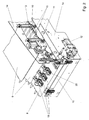
- the in the FIGS. 2 to 4 extracting and pressing device 7 shown in more detail in detail has two machine-width, circulating conveyor belts 8, 9, whose inner, conveying strands are arranged horizontally and parallel to one another with a slight spacing from one another.
- Each of the conveyor belts 8, 9 revolves around a drive roller 10, 11, which is in each case directly connected to a drive 12, 13.
- Each of the drives 12, 13 consists of a speed-controlled servo motor with resolver, preferably three-phase servo motors are used with resolver feedback, in which the rotation angle detected and used to control the motor.
- These motors are very precisely controlled and can accelerate and decelerate very quickly. In addition, they have relatively high torques at relatively low speeds.
- the two drives 12, 13 are separated so controlled by a central control device, so that a speed difference can be adjusted. They are attached to side frame walls 14 of the device.
- the associated switch boxes are each arranged outside the drives 12, 13 and cover so their lateral outer end. The switch boxes thus also serve as protection and prevent injuries to the operators.
- Both conveying strands of the conveyor belts 8, 9 are each supported on their back by a series of transverse support rollers 15, 16.
- the lower conveyor belt 8 begins at the inlet side in front of the upper conveyor belt 9. Above the exposed area of the lower conveyor belt 8, three belt conveyors 19 are arranged, each with the lower conveyor belt 8 form a tapered inlet gap for the blanks.
- the short belt conveyors serve to produce a precisely aligned cutting stream, which is then guided between the pressing conveyor belts 8, 9.
- the three belt conveyors 19 are arranged at a distance next to each other and can be individually positioned transversely with an adjusting 21,22.
- the belts 20 of the belt conveyors 19 are driven together by a transverse drive shaft, which is connected via a belt drive to the drive 13 (not shown).
- Each belt conveyor 19 has its own pivot drive, which allows a motorized adjustment of the inlet gap from the outside.
- a geared motor 29 is fixed to the rear of the bearing plate 24, which drives a worm 31 via a slip clutch 30.
- the worm 31 drives a pivot shaft 32 which passes through the bearing plate 24 and which is connected at its other end to the auxiliary plate 27.
Landscapes
- Making Paper Articles (AREA)
- Structure Of Belt Conveyors (AREA)
- Control Of Conveyors (AREA)
Description
- Die Erfindung betrifft eine Sammel- und Presseinrichtung, einer Faltschachtelklebemaschine mit zwei maschinenbreiten, umlaufenden Förderbändern, die mit einem Antrieb verbunden sind und deren fördernde Trums horizontal und parallel zueinander verlaufend übereinander angeordnet sind, wobei der obere, fördernde Trum des unteren Förderbandes gegenüber dem unteren, fördernden Trum des oberen Förderbandes zum Pressen der gefalteten Zuschnitte vertikal bewegbar gelagert ist.
- Faltschachtelklebemaschinen zur Herstellung von Faltschachteln aus Zuschnitten weisen bekannter Weise zumindest die folgenden Bearbeitungsstationen auf:
- Einen Einleger, der die zu verarbeitenden Zuschnitte mit hoher Geschwindigkeit aus einem Stapel nacheinander abzieht und einzeln der nachfolgenden Bearbeitungsstation zuführt,
- eine Faltstation, in der die mit einem Klebestreifen versehenen Zuschnittteile zur Herstellung einer Klebeverbindung gefaltet werden,
- eine Überleitstation, von der die gefalteten Zuschnitte exakt ausgerichtet der nachfolgenden Sammel- und Presseinrichtung zugeführt werden, und
- eine Sammel- und Preßeinrichtung, in der zunächst ein Schuppenstrom aus gefalteten Zuschnitten gebildet wird, der anschließend zwischen als Preßbänder ausgestalteten Förderbändern unter Druck gehalten weitergefördert wird, damit die Klebenähte abbinden.
- Die bekannten Sammel- und Preßeinrichtungen weisen einen gemeinsamen Antrieb für die oberen und unteren Förderbänder auf, von dem jeweils eine von dem jeweiligen Förderband umlaufene Antriebswalze über eine Kette angetrieben wird. Der untere, fördernde Trum des oberen Förderbandes und der obere, fördernde Trum des unteren Förderbandes sind jeweils an ihrer Rückseite von Stützrollen abgestützt, damit zwischen diesen beiden Trums die gefalteten Zuschnitte unter Druck halten gefördert werden. Die Stützrollen des unteren Förderbandes sind gegen eine Federkraft nach unten bewegbar gelagert, damit unterschiedlich dicke Schachtelströme bei einem einstellbaren Pressdruck durchgefördert werden können.
- Bei den bekannten Sammel- und Presseinrichtungen hat sich gezeigt, dass in Abhängigkeit vom herzustellenden Schachteltyp die Verarbeitungsgeschwindigkeit begrenzt und/oder die Qualität der hergestellten Schachteln beeinträchtigt ist.
-
US 5 151 075 A offenbart eine Sammel- und Presseinrichtung des Oberbegriffs des Anspruchs 1. - Der Erfindung liegt daher die Aufgabe zugrunde, eine Sammel- und Presseinrichtung einer Faltschachtelklebemaschine der gattungsgemäßen Art so zu verbessern, dass auch komplizierte Schachteltypen mit erhöhter Produktionsgeschwindigkeit und hoher Qualität hergestellt werden können.
- Diese Aufgabe wird durch die Sammel-und Presseinrichtung mit dem Merkmaler des Anspruchs 1 gelöst.
- In einer bevorzugten Ausgestallung der Sammel-und Presseinrichtung weist der Schwenkantrieb einen Getriebemotor, eine Rutschkupplung und eine Schnecke, wobei die Schnecke eine Schwenkwelle antreibt, die mit einer Zusatzplatte verbunden ist, welche die Umlenkrollen eines anderen Förderbandes auf der Einlaufseite trägt.
- In einer weiteren bevorzugten Ausgestally sind drei Riemenförderer angeordnet.
- Diese Lösung mit hochdynamischen Antrieben ermöglicht eine höhere Produktionsgeschwindigkeit bei hoher Produktqualität, da die Antriebe schneller abgebremst und beschleunigt werden können und zudem mit einer Geschwindigkeitsdifferenz betrieben werden können. Sehr kurze Abbremszeiten und Beschleunigungszeiten sind erforderlich, falls durch Auswurfsysteme einzelne Zuschnitte vorher aus der Maschine entfernt wurden, beispielsweise weil sie fehlerhaft sind. Um für einen konstanten Schuppenstrom, den ein nachfolgender Abpackautomat erfordert, die beim Auswerfen eines Zuschnitts entstandene Lücke zu schließen, müssen die Förderbänder kurzzeitig abgebremst und anschließend wieder beschleunigt werden. Dies führt bei dem bekannten Antrieb zu erheblichen Belastungen der mechanischen Elemente, so dass die Produktionsgeschwindigkeit begrenzt ist.
- Durch das Fehlen der Verbindungskette entfällt beim Abbremsen und Beschleunigen die druckweise Verschiebung des oberen Förderbandes zum unteren Förderband, zudem wird der Verschleiß erheblich verringert. Dies ermöglicht es, die Maximalgeschwindigkeit der Förderbänder um ca. 50 % auf ca. 60 m/min. zu erhöhen.
- Weiterhin hat sich gezeigt, dass bei den bekannten, antriebsmäßig starr gekoppelten Förderbändern Qualitätsbeeinträchtigungen bei den Fertigprodukten auftreten können. Das untere, nachgiebig gelagerte Förderband weicht unter dem anliegenden Druck nach unten aus. Durch das Ausweichen muss das untere Förderband zum Teil eine längere Strecke zurücklegen als das obere Förderband. Da aufgrund der starren Kopplung die Fördergeschwindigkeiten gleich sind, baut sich eine Spannung auf, die dazu führt, dass exakt übereinanderliegend zugeförderten Schachtelteile gegeneinander verschoben werden. Bevorzugt sind nach der Erfindung die Antriebe der beiden Förderbänder über eine gemeinsame Steuereinrichtung relativ zueinander regelbar. Es kann somit eine Geschwindigkeitsdifferenz zwischen dem oberen Förderband und dem unteren Förderband eingestellt werden, um ein Verschieben von Schachtelteilen gegeneinander zu vermeiden.
- Nachfolgend wird die Erfindung anhand eines in den Zeichnungen dargestellten Ausführungsbeispiels beschrieben.
- Fig. 1
- zeigt in einer schematischen Seitenansicht einzelne Stationen einer Faltschachtelklebemaschine,
- Fig. 2
- zeigt in einer perspektivischen Darstellung einen Teil der Sammel- und Presseinrichtung,
- Figs. 3 und 4
- zeigen in perspektivischer Darstellung einen der Riemenförderer, die an der Einlaufseite angeordnet sind.
- In Förderrichtung (von links nach rechts) beginnt die Faltschachtelmaschine mit einem Einleger 1, der die zu verarbeitenden Zuschnitte mit hoher Geschwindigkeit aus einem Stapel nacheinander abzieht und einzeln der nachfolgenden Bearbeitungssation zuführt. Auf den Einleger 1 folgen als nächste Bearbeitungsstationen zwei Vorbrecher 2, 3, die Faltelemente enthalten, um Faltlappen vor und zurück zu falten. Durch das Knicken um 180° werden die entsprechenden Linksrilllinien der Zuschnitte weich und geschmeidig gemacht.
- Auf den Vorbrecher 3 folgt als nächste Bearbeitungsstation die Faltstation 4, an deren Anfang ein Auftragwerk 5 für Klebstoff, üblicherweise Leim, angeordnet ist. Das Klebstoffauftragwerk 5 enthält Leimdüsen oder Leimscheiben, von denen der Klebstoff streifenförmig auf die Zuschnitte aufgebracht wird. Anschließend werden die Faltlappen der Zuschnitte von Faltelementen gefaltet.
- Als nächste Station folgt eine Überleitstation 6, in der die gefalteten, mit noch nicht abgebundenen Klebenähten versehenen Zuschnitte in allen Teilen exakt ausgerichtet einer nachfolgenden Sammel- und Preßeinrichtung 7 zugeführt werden. Im Bereich der Überleitstation 6 können Einrichtungen angeordnet werden, mit denen die Schachteln gezählt, markiert und - falls schadhaft - ausgeschleust werden. In der Sammel- und Preßeinrichtung 7 wird zunächst ein Schuppenstrom aus gefalteten Zuschnitten gebildet, der anschließend zwischen Preßbändern für einige Zeit unter Druck gehalten wird, damit die Klebenähte abbinden. Zum Abschluß ist häufig eine Packeinrichtung angeordnet, in der die flachliegend gefalteten Faltschachteln in Umkartons gepackt werden.
- Die in den
Figuren 2 bis 4 auszugsweise detaillierter dargestellte Sammel- und Presseinrichtung 7 weist zwei maschinenbreite, umlaufende Förderbänder 8, 9 auf, deren innere, fördernde Trums horizontal und parallel mit geringem Abstand zueinander verlaufend übereinander angeordnet sind. Jedes der Förderbänder 8, 9 umläuft eine Antriebswalze 10, 11, die jeweils direkt mit einem Antrieb 12, 13 verbunden ist. Jeder der Antriebe 12, 13 besteht aus einem geschwindigkeitsgeregelten Servomotor mit Resolver, bevorzugt werden Drehstrom-Servomotoren mit Resolverrückführung verwendet, bei denen die Drehwinkel erfaßt und zur Regelung des Motors verwendet werden. Diese Motoren sind sehr genau steuerbar und können sehr schnell beschleunigen und abbremsen. Zudem haben sie bei relativ geringen Geschwindigkeiten relativ hohe Drehmomente. - Die beiden Antriebe 12, 13 sind von einer zentralen Steuereinrichtung getrennt so steuerbar, so dass eine Geschwindigkeitsdifferenz eingestellt werden kann. Sie sind an seitlichen Gestellwänden 14 der Einrichtung befestigt. Bevorzugt sind die zugehörigen Schaltkästen jeweils außen neben den Antrieben 12, 13 angeordnet und decken so deren seitliches äußeres Ende ab. Die Schaltkästen dienen so zugleich als Schutz und verhindern Verletzungen der Bedienpersonen.
- Beide fördernden Trums der Förderbänder 8, 9 werden jeweils an ihrer Rückseite von einer Reihe von querverlaufenden Stützrollen 15, 16 abgestützt.
- Wie aus
Figur 2 ersichtlich, beginnt das untere Förderband 8 an der Einlaufseite vor dem oberen Förderband 9. Oberhalb des freiliegenden Bereichs des unteren Förderbandes 8 sind drei Riemenförderer 19 angeordnet, die jeweils mit dem
unteren Förderband 8 einen zulaufenden Einlaufspalt für die Zuschnitte bilden. Die kurzen Riemenförderer dienen dazu, einen exakt ausgerichteten Zuschnittsstrom zu erzeugen, der anschließend zwischen die pressenden Förderbänder 8, 9 geführt wird. - Die drei Riemenförderer 19 sind mit Abstand nebeneinander angeordnet und können einzeln mit einem Verstellantrieb 21,22 quer positioniert werden. Die Riemen 20 der Riemenförderer 19 werden gemeinsam von einer quer verlaufenden Antriebswelle angetrieben, die über einen Riementrieb am Antrieb 13 angeschlossen ist (nicht dargestellt).
- Der Aufbau eines Riemenförderers 19 ist in den
Figuren 3 und 4 detaillierter dargestellt: - Jeder Riemenförderer enthält einen umlaufenden Riemen 20, der über Umlenkrollen 23 geführt ist, die in einer quer verschiebbaren Lagerplatte 24 gelagert sind. Der untere, fördernde Trum 25 verläuft in seinem hinteren Teil (in
Figur 3 links) horizontal und somit parallel zum unteren Förderband 8. Die drei einlaufseitigen Umlenkrollen 26 sind an einer Zusatzplatte 27 gelagert, die um eine Achse 28 schwenkbar an der Lagerplatte 24 befestigt ist. Der einlaufseitige Teil jedes Riemenförderers kann so zur Änderung des Einlaufspalts nach oben und unten verschwenkt werden. - Jeder Riemenförderer 19 weist einen eigenen Schwenkantrieb auf, der eine motorische Verstellung des Einlaufspalts von außen ermöglicht. Wie in Figur 5 dargestellt, ist an der Rückseite der Lagerplatte 24 ein Getriebemotor 29 befestigt, der über eine Rutschkupplung 30 eine Schnecke 31 antreibt. Die Schnecke 31 treibt eine Schwenkwelle 32 an, die durch die Lagerplatte 24 führt und die an ihrem anderen Ende mit der Zusatzplatte 27 verbunden ist. So läßt sich für jeden Riemenförderer 19 der Einlaufspalt von außen getrennt einstellen und während des Betriebes korrigieren, falls sich die Maschinengeschwindigkeit ändert. Es ist nicht mehr erforderlich, dass eine Bedienperson zur Korrektur des Einlaufspalts in die laufende Vorrichtung eingreift.
-
- 1
- Einleger
- 2
- Vorbrecher
- 3
- Vorbrecher
- 4
- Faltstation
- 5
- Klebstoffauftragwerk
- 6
- Überleitstation
- 7
- Presseinrichtung
- 8
- Förderband
- 9
- Förderband
- 10
- Antriebswalze
- 11
- Antriebswalze
- 12
- Antrieb
- 13
- Antrieb
- 14
- Gestellwand
- 15
- Stützwalze
- 16
- Stützwalze
- 17
- Lagerplatte
- 19
- Riemenförderer
- 20
- Riemen
- 21
- Verstellantrieb
- 22
- Verstellantrieb
- 23
- Umlenkrolle
- 24
- Lagerplatte
- 25
- unteres, förderndes Trum
- 26
- Umlenkrolle
- 27
- Zusatzplatte
- 28
- Achse
- 29
- Getriebemotor
- 30
- Rutschkupplung
- 31
- Schnecke
- 32
- Schwenkwelle
Claims (3)
- Sammel- und Presseinrichtung (7) einer Faltschachtelklebemaschine mit zwei maschinenbreiten, umlaufenden Förderbändern (8, 9), die mit einem Antrieb verbunden sind und deren fördernde Trums horizontal und parallel zueinander verlaufend übereinander angeordnet sind, wobei der obere, fördernde Trum des unteren Förderbandes (8) gegenüber dem unteren, fördernden Trum des oberen Förderbandes (9) zum Pressen der gefalteten Zuschnitte vertikal bewegbar gelagert ist, wobei sowohl das untere Förderband (8) als auch das obere Förderband (9) einen eigenen Antrieb (12, 13) aufweisen und das untere Förderband (8) an der Einlaufseite vor dem oberen Förderband (9) beginnt,
dadurch gekennzeichnet, dass sowohl der Antrieb des unteren Förderbandes (8) als auch der Antrieb des oberen Förderbandes (9) aus einem direkt an die jeweilige Antriebswalze (10, 11) angeschlossenen Servomotor mit Resolver besteht, oberhalb des freiliegenden Bereichs des unteren Förderbandes (8) mindestens zwei kurze Riemenförderer (19) angeordnet sind, die jeweils mit dem unteren Förderband (8) einen zulaufenden Einlaufspalt für die Zuschnitte bilden, und jeder Riemenförderer (19) seinen eigenen Schwenkantrieb (29, 30, 31) aufweist, so dass der einlaufseitige Teil jedes Riemenförderers (19) zur Änderung des Einlaufspalts nach oben und unten verschwenkt werden kann. - Einrichtung nach Anspruch 1,
dadurch gekennzeichnet, dass der Schwenkantrieb einen Getriebemotor (29), eine Rutschkupplung (30) und eine Schnecke (31) aufweist, wobei die Schnecke eine Schwenkwelle antreibt, die mit einer Zusatzplatte (27) verbunden ist, welche die Umlenkrollen eines anderen Förderbandes auf der Einlaufseite trägt. - Einrichtung nach Anspruch 1 oder 2,
dadurch gekennzeichnet, dass drei kurze Riemenförderer (19) angeordnet sind.
Applications Claiming Priority (2)
| Application Number | Priority Date | Filing Date | Title |
|---|---|---|---|
| DE102004022209 | 2004-05-04 | ||
| DE102004022209A DE102004022209A1 (de) | 2004-05-04 | 2004-05-04 | Sammel- und Presseinrichtung einer Faltschachtelklebemaschine |
Publications (3)
| Publication Number | Publication Date |
|---|---|
| EP1593483A2 EP1593483A2 (de) | 2005-11-09 |
| EP1593483A3 EP1593483A3 (de) | 2007-11-14 |
| EP1593483B1 true EP1593483B1 (de) | 2016-11-30 |
Family
ID=34939570
Family Applications (1)
| Application Number | Title | Priority Date | Filing Date |
|---|---|---|---|
| EP05103498.1A Expired - Lifetime EP1593483B1 (de) | 2004-05-04 | 2005-04-28 | Sammel- und Presseinrichtung einer Faltschachtelklebemaschine |
Country Status (6)
| Country | Link |
|---|---|
| US (1) | US7258655B2 (de) |
| EP (1) | EP1593483B1 (de) |
| JP (1) | JP2005319802A (de) |
| CN (1) | CN1727177B (de) |
| DE (1) | DE102004022209A1 (de) |
| ES (1) | ES2616541T3 (de) |
Families Citing this family (14)
| Publication number | Priority date | Publication date | Assignee | Title |
|---|---|---|---|---|
| CN100436289C (zh) * | 2006-02-27 | 2008-11-26 | 常熟市伟成非织造成套设备有限公司 | 喂料机 |
| EP2826618A3 (de) * | 2006-11-08 | 2015-04-08 | Heidelberger Druckmaschinen AG | Faltschachtelklebemaschine zur Herstellung von Faltschachteln aus Zuschnitten |
| IT1396784B1 (it) * | 2009-11-25 | 2012-12-14 | Gingardi | Apparecchiatura per la finitura dei prodotti uscenti da una macchina per la piegatura ed incollatura di prodotti in cartone o cartoncino con dorso. |
| KR101094398B1 (ko) * | 2009-11-27 | 2011-12-15 | 김대근 | 스티칭 머신의 급지장치 |
| JP5397260B2 (ja) * | 2010-02-18 | 2014-01-22 | ブラザー工業株式会社 | 布接着装置、及びカートリッジ |
| DE102010036015A1 (de) * | 2010-08-31 | 2012-03-01 | Heidelberger Druckmaschinen Ag | Faltschachtelklebemaschine |
| CN102673016A (zh) * | 2011-03-07 | 2012-09-19 | 上海艾录纸包装有限公司 | 提高粘合效果的紧压装置 |
| JP6054515B2 (ja) * | 2012-04-23 | 2016-12-27 | ボブスト メックス ソシエテ アノニム | フレームを含むモジュール及びこれを装備するフォルダ・グルア |
| JP6792193B2 (ja) * | 2016-09-01 | 2020-11-25 | セイコーエプソン株式会社 | 媒体支持ユニット、印刷装置、加熱装置及び印刷方法 |
| PL3784603T3 (pl) | 2018-04-25 | 2022-05-23 | Autostore Technology AS | Pojazd do obsługi pojemników z pierwszą i drugą sekcją oraz większymi silnikami kół na dwóch spośród kół w drugiej sekcji |
| CN110588058A (zh) * | 2019-10-25 | 2019-12-20 | 中科天工(武汉)智能技术有限公司 | 可调盒通道、可调切边通道以及切边取模装置 |
| CN114261142B (zh) * | 2021-12-23 | 2024-04-09 | 浙江新元创自动化设备股份有限公司 | 一种用于瓦楞纸箱糊口精度保证的方法 |
| DE102022105319A1 (de) | 2022-03-08 | 2023-09-14 | Koenig & Bauer Ag | Vorrichtung zum Transport von Substratbogen und Maschine |
| CN115042479B (zh) * | 2022-06-30 | 2023-11-17 | 温州永邦机械有限公司 | 一种具有真空吸附的瓦裱机 |
Family Cites Families (26)
| Publication number | Priority date | Publication date | Assignee | Title |
|---|---|---|---|---|
| US2391170A (en) * | 1942-08-20 | 1945-12-18 | Int Paper Box Machine Co | Stacker accumulator |
| DE850989C (de) * | 1947-02-10 | 1952-09-29 | Bobst & Sohn A G J | Bogenableger fuer gefaltete und geklebte Pappbogen |
| US3045586A (en) * | 1959-04-28 | 1962-07-24 | Expeller Press And Chemical Co | Conveyor press |
| US3054514A (en) * | 1960-12-22 | 1962-09-18 | United States Steel Corp | Tilting device for heavy articles |
| US3292504A (en) * | 1963-03-06 | 1966-12-20 | Jagenberg Werke Ag | Apparatus for producing folded boxes or containers having adhered seams |
| US3605585A (en) * | 1969-06-11 | 1971-09-20 | Fred Borders | Apparatus for the manufacture of boxes |
| US4102252A (en) * | 1977-03-25 | 1978-07-25 | Abc Packaging Machine Corporation | Continuous motion apparatus and method for sealing cartons |
| JPS5757955Y2 (de) * | 1978-12-29 | 1982-12-11 | ||
| US4551708A (en) * | 1982-06-04 | 1985-11-05 | Motornetics Corporation | Reactance-commutated high resolution servo motor system |
| FR2544658B1 (fr) * | 1983-04-22 | 1985-12-20 | Dev Mat Emballage | Intallation pour produire des caisses en carton sous forme pliee |
| US4519181A (en) * | 1983-06-07 | 1985-05-28 | Johns-Manville Corporation | Sleeve carton end panel and flap folding and sealing assembly |
| US4683704A (en) * | 1983-10-18 | 1987-08-04 | Pemco, Inc. | Method of and apparatus for wrapping |
| DE3743728A1 (de) * | 1987-12-23 | 1989-07-06 | Jagenberg Ag | Maschine und verfahren zur herstellung von gefalteten behaeltern, insbesondere von faltschachteln |
| US5151075A (en) * | 1990-11-05 | 1992-09-29 | J & L Industries, Inc. | Carton folding apparatus |
| EP0654434B1 (de) * | 1993-11-19 | 2000-04-05 | Ferag AG | Pressvorrichtung für gefaltete Druckereierzeugnisse wie Zeitungen, Zeitschriften und Teilen hievon |
| US5706627A (en) | 1994-02-02 | 1998-01-13 | Tetra Laval Holdings & Finance, S.A. | Control system for a packaging machine |
| DE4439198A1 (de) * | 1994-11-06 | 1996-05-09 | Klett Alfred | Vorrichtung zur Bearbeitung eines entlang eines Förderwegs mit vorgegebener Fördergeschwindigkeit geförderten Zuschnitts |
| US5827162A (en) * | 1997-01-02 | 1998-10-27 | The Langston Corporation | Folder/gluer machine for paperboard blanks |
| JPH10329239A (ja) * | 1997-06-03 | 1998-12-15 | Kameya:Kk | 折畳段ボール矯正搬送装置 |
| CN2336959Y (zh) * | 1998-03-16 | 1999-09-08 | 济宁合力科工贸有限责任公司 | 一种叠粘式全封闭瓦楞纸箱合箱机 |
| DE19828821B4 (de) * | 1998-06-04 | 2006-04-06 | Heidelberger Druckmaschinen Ag | Faltschachtelklebemaschine zur Herstellung von Faltschachteln aus Zuschnitten |
| DE19828820C2 (de) | 1998-06-04 | 2003-04-03 | Jagenberg Diana Gmbh | Faltschachtelklebemaschine zur Herstellung von Faltschachteln aus Zuschnitten |
| EP1001878B1 (de) | 1998-06-04 | 2004-03-31 | Heidelberger Druckmaschinen Aktiengesellschaft | Faltschachtelklebemaschine zur herstellung von faltschachteln aus zuschnitten |
| DE69903307T2 (de) * | 1998-07-09 | 2003-06-26 | Bobst Group Inc., Roseland | Vorrichtung mit pneumatischen fingerelementen zum aufrichten von faltschachteln |
| US6475128B1 (en) * | 1999-05-26 | 2002-11-05 | J&L Development, Inc. | Apparatus and method for individually controlling motors in a carton folding machine in order to automatically execute a carton folding process |
| CH695144A5 (fr) * | 2002-04-03 | 2005-12-30 | Bobst Sa | Dispositif introducteur rectificateur d'une plieuse-colleuse. |
-
2004
- 2004-05-04 DE DE102004022209A patent/DE102004022209A1/de not_active Ceased
-
2005
- 2005-04-28 ES ES05103498.1T patent/ES2616541T3/es not_active Expired - Lifetime
- 2005-04-28 EP EP05103498.1A patent/EP1593483B1/de not_active Expired - Lifetime
- 2005-04-30 CN CN2005100922683A patent/CN1727177B/zh not_active Expired - Lifetime
- 2005-05-04 US US11/122,878 patent/US7258655B2/en not_active Expired - Lifetime
- 2005-05-06 JP JP2005135204A patent/JP2005319802A/ja active Pending
Also Published As
| Publication number | Publication date |
|---|---|
| JP2005319802A (ja) | 2005-11-17 |
| ES2616541T3 (es) | 2017-06-13 |
| EP1593483A2 (de) | 2005-11-09 |
| US20050250634A1 (en) | 2005-11-10 |
| EP1593483A3 (de) | 2007-11-14 |
| DE102004022209A1 (de) | 2005-12-01 |
| CN1727177B (zh) | 2010-05-05 |
| CN1727177A (zh) | 2006-02-01 |
| US7258655B2 (en) | 2007-08-21 |
Similar Documents
| Publication | Publication Date | Title |
|---|---|---|
| EP2060514B1 (de) | Vorrichtung zum Drehen flacher Gegenstände, insbesondere von Faltschachtelzuschnitten | |
| DE102004022217B4 (de) | Faltschachtelklebemaschine zur Herstellung von Faltschachteln aus Zuschnitten | |
| DE69702667T2 (de) | Vorrichtung zum montieren von sägezahnschneidestreifen | |
| EP2422970B1 (de) | Faltschachtelklebemaschine | |
| DE69511900T2 (de) | Vorrichtung zum falten von folien durch ein endloses förderband | |
| EP2163376B1 (de) | Faltschachtelklebemaschine zur herstellung von faltschachteln aus zuschnitten | |
| EP2826618A2 (de) | Faltschachtelklebemaschine zur Herstellung von Faltschachteln aus Zuschnitten | |
| EP1593483A2 (de) | Sammel- und Presseinrichtung einer Faltschachtelklebemaschine | |
| EP1001877B1 (de) | Faltschachtelklebemaschine zur herstellung von faltschachteln aus zuschnitten | |
| EP2423137B1 (de) | Transportvorrichtung | |
| EP0735979A1 (de) | Verfahren und vorrichtung zum herstellen eines längsfalzes | |
| DE19828820C2 (de) | Faltschachtelklebemaschine zur Herstellung von Faltschachteln aus Zuschnitten | |
| EP1593484B1 (de) | Faltschachtelklebemaschine zur Herstellung von Faltschachteln aus Zuschnitten | |
| EP1593485B1 (de) | Faltschachtelklebemaschine zur Herstellung von Faltschachteln aus Zuschnitten | |
| DE69803508T2 (de) | Vorrichtung zum Verpacken von Gegenständen unterschiedlicher Dicke | |
| EP1001878B1 (de) | Faltschachtelklebemaschine zur herstellung von faltschachteln aus zuschnitten | |
| EP3272548A1 (de) | Maschine zur automatisierten herstellung von bucheinbanddecken | |
| EP1218168A1 (de) | Faltschachtelklebemaschine zur herstellung von faltschachteln aus zuschnitten | |
| EP0677473A2 (de) | Vorrichtung zum Falten oder dgl. von Blattlagen | |
| EP3228446B1 (de) | Rilllinienpressstation | |
| EP2514678A1 (de) | Antriebsordnung für eine Folienverpackungsmaschine | |
| DE19828821B4 (de) | Faltschachtelklebemaschine zur Herstellung von Faltschachteln aus Zuschnitten | |
| DE102014010572A1 (de) | Faltschachtelklebemaschine mit Schneidestation | |
| DE102019120431A1 (de) | Vorrichtung und Verfahren für den Transport eines Druckprodukts | |
| EP2476546B1 (de) | Vorrichtung zum Ausrichten flacher Gegenstände, insbesondere von Faltschachtelzuschnitten |
Legal Events
| Date | Code | Title | Description |
|---|---|---|---|
| PUAI | Public reference made under article 153(3) epc to a published international application that has entered the european phase |
Free format text: ORIGINAL CODE: 0009012 |
|
| AK | Designated contracting states |
Kind code of ref document: A2 Designated state(s): AT BE BG CH CY CZ DE DK EE ES FI FR GB GR HU IE IS IT LI LT LU MC NL PL PT RO SE SI SK TR |
|
| AX | Request for extension of the european patent |
Extension state: AL BA HR LV MK YU |
|
| PUAL | Search report despatched |
Free format text: ORIGINAL CODE: 0009013 |
|
| AK | Designated contracting states |
Kind code of ref document: A3 Designated state(s): AT BE BG CH CY CZ DE DK EE ES FI FR GB GR HU IE IS IT LI LT LU MC NL PL PT RO SE SI SK TR |
|
| AX | Request for extension of the european patent |
Extension state: AL BA HR LV MK YU |
|
| 17P | Request for examination filed |
Effective date: 20080514 |
|
| AKX | Designation fees paid |
Designated state(s): AT BE BG CH CY CZ DE DK EE ES FI FR GB GR HU IE IS IT LI LT LU MC NL PL PT RO SE SI SK TR |
|
| 17Q | First examination report despatched |
Effective date: 20080626 |
|
| RAP1 | Party data changed (applicant data changed or rights of an application transferred) |
Owner name: MASTERWORK MACHINERY CO., LTD. |
|
| GRAP | Despatch of communication of intention to grant a patent |
Free format text: ORIGINAL CODE: EPIDOSNIGR1 |
|
| INTG | Intention to grant announced |
Effective date: 20160610 |
|
| GRAS | Grant fee paid |
Free format text: ORIGINAL CODE: EPIDOSNIGR3 |
|
| GRAA | (expected) grant |
Free format text: ORIGINAL CODE: 0009210 |
|
| AK | Designated contracting states |
Kind code of ref document: B1 Designated state(s): AT BE BG CH CY CZ DE DK EE ES FI FR GB GR HU IE IS IT LI LT LU MC NL PL PT RO SE SI SK TR |
|
| REG | Reference to a national code |
Ref country code: CH Ref legal event code: EP Ref country code: GB Ref legal event code: FG4D Free format text: NOT ENGLISH |
|
| REG | Reference to a national code |
Ref country code: AT Ref legal event code: REF Ref document number: 849397 Country of ref document: AT Kind code of ref document: T Effective date: 20161215 |
|
| REG | Reference to a national code |
Ref country code: IE Ref legal event code: FG4D Free format text: LANGUAGE OF EP DOCUMENT: GERMAN |
|
| REG | Reference to a national code |
Ref country code: DE Ref legal event code: R096 Ref document number: 502005015437 Country of ref document: DE |
|
| REG | Reference to a national code |
Ref country code: LT Ref legal event code: MG4D |
|
| REG | Reference to a national code |
Ref country code: NL Ref legal event code: MP Effective date: 20161130 |
|
| PG25 | Lapsed in a contracting state [announced via postgrant information from national office to epo] |
Ref country code: SE Free format text: LAPSE BECAUSE OF FAILURE TO SUBMIT A TRANSLATION OF THE DESCRIPTION OR TO PAY THE FEE WITHIN THE PRESCRIBED TIME-LIMIT Effective date: 20161130 Ref country code: GR Free format text: LAPSE BECAUSE OF FAILURE TO SUBMIT A TRANSLATION OF THE DESCRIPTION OR TO PAY THE FEE WITHIN THE PRESCRIBED TIME-LIMIT Effective date: 20170301 Ref country code: LT Free format text: LAPSE BECAUSE OF FAILURE TO SUBMIT A TRANSLATION OF THE DESCRIPTION OR TO PAY THE FEE WITHIN THE PRESCRIBED TIME-LIMIT Effective date: 20161130 |
|
| REG | Reference to a national code |
Ref country code: FR Ref legal event code: PLFP Year of fee payment: 13 |
|
| PG25 | Lapsed in a contracting state [announced via postgrant information from national office to epo] |
Ref country code: PL Free format text: LAPSE BECAUSE OF FAILURE TO SUBMIT A TRANSLATION OF THE DESCRIPTION OR TO PAY THE FEE WITHIN THE PRESCRIBED TIME-LIMIT Effective date: 20161130 Ref country code: PT Free format text: LAPSE BECAUSE OF FAILURE TO SUBMIT A TRANSLATION OF THE DESCRIPTION OR TO PAY THE FEE WITHIN THE PRESCRIBED TIME-LIMIT Effective date: 20170330 Ref country code: FI Free format text: LAPSE BECAUSE OF FAILURE TO SUBMIT A TRANSLATION OF THE DESCRIPTION OR TO PAY THE FEE WITHIN THE PRESCRIBED TIME-LIMIT Effective date: 20161130 |
|
| REG | Reference to a national code |
Ref country code: ES Ref legal event code: FG2A Ref document number: 2616541 Country of ref document: ES Kind code of ref document: T3 Effective date: 20170613 |
|
| PG25 | Lapsed in a contracting state [announced via postgrant information from national office to epo] |
Ref country code: NL Free format text: LAPSE BECAUSE OF FAILURE TO SUBMIT A TRANSLATION OF THE DESCRIPTION OR TO PAY THE FEE WITHIN THE PRESCRIBED TIME-LIMIT Effective date: 20161130 |
|
| PG25 | Lapsed in a contracting state [announced via postgrant information from national office to epo] |
Ref country code: RO Free format text: LAPSE BECAUSE OF FAILURE TO SUBMIT A TRANSLATION OF THE DESCRIPTION OR TO PAY THE FEE WITHIN THE PRESCRIBED TIME-LIMIT Effective date: 20161130 Ref country code: SK Free format text: LAPSE BECAUSE OF FAILURE TO SUBMIT A TRANSLATION OF THE DESCRIPTION OR TO PAY THE FEE WITHIN THE PRESCRIBED TIME-LIMIT Effective date: 20161130 Ref country code: EE Free format text: LAPSE BECAUSE OF FAILURE TO SUBMIT A TRANSLATION OF THE DESCRIPTION OR TO PAY THE FEE WITHIN THE PRESCRIBED TIME-LIMIT Effective date: 20161130 Ref country code: DK Free format text: LAPSE BECAUSE OF FAILURE TO SUBMIT A TRANSLATION OF THE DESCRIPTION OR TO PAY THE FEE WITHIN THE PRESCRIBED TIME-LIMIT Effective date: 20161130 Ref country code: CZ Free format text: LAPSE BECAUSE OF FAILURE TO SUBMIT A TRANSLATION OF THE DESCRIPTION OR TO PAY THE FEE WITHIN THE PRESCRIBED TIME-LIMIT Effective date: 20161130 |
|
| PG25 | Lapsed in a contracting state [announced via postgrant information from national office to epo] |
Ref country code: BG Free format text: LAPSE BECAUSE OF FAILURE TO SUBMIT A TRANSLATION OF THE DESCRIPTION OR TO PAY THE FEE WITHIN THE PRESCRIBED TIME-LIMIT Effective date: 20170228 |
|
| REG | Reference to a national code |
Ref country code: DE Ref legal event code: R097 Ref document number: 502005015437 Country of ref document: DE |
|
| PLBE | No opposition filed within time limit |
Free format text: ORIGINAL CODE: 0009261 |
|
| STAA | Information on the status of an ep patent application or granted ep patent |
Free format text: STATUS: NO OPPOSITION FILED WITHIN TIME LIMIT |
|
| 26N | No opposition filed |
Effective date: 20170831 |
|
| PG25 | Lapsed in a contracting state [announced via postgrant information from national office to epo] |
Ref country code: SI Free format text: LAPSE BECAUSE OF FAILURE TO SUBMIT A TRANSLATION OF THE DESCRIPTION OR TO PAY THE FEE WITHIN THE PRESCRIBED TIME-LIMIT Effective date: 20161130 |
|
| REG | Reference to a national code |
Ref country code: IE Ref legal event code: MM4A |
|
| PG25 | Lapsed in a contracting state [announced via postgrant information from national office to epo] |
Ref country code: MC Free format text: LAPSE BECAUSE OF FAILURE TO SUBMIT A TRANSLATION OF THE DESCRIPTION OR TO PAY THE FEE WITHIN THE PRESCRIBED TIME-LIMIT Effective date: 20161130 |
|
| PG25 | Lapsed in a contracting state [announced via postgrant information from national office to epo] |
Ref country code: LU Free format text: LAPSE BECAUSE OF NON-PAYMENT OF DUE FEES Effective date: 20170428 |
|
| REG | Reference to a national code |
Ref country code: BE Ref legal event code: MM Effective date: 20170430 |
|
| REG | Reference to a national code |
Ref country code: FR Ref legal event code: PLFP Year of fee payment: 14 |
|
| PG25 | Lapsed in a contracting state [announced via postgrant information from national office to epo] |
Ref country code: IE Free format text: LAPSE BECAUSE OF NON-PAYMENT OF DUE FEES Effective date: 20170428 |
|
| PG25 | Lapsed in a contracting state [announced via postgrant information from national office to epo] |
Ref country code: BE Free format text: LAPSE BECAUSE OF NON-PAYMENT OF DUE FEES Effective date: 20170430 |
|
| REG | Reference to a national code |
Ref country code: AT Ref legal event code: MM01 Ref document number: 849397 Country of ref document: AT Kind code of ref document: T Effective date: 20170428 |
|
| PG25 | Lapsed in a contracting state [announced via postgrant information from national office to epo] |
Ref country code: AT Free format text: LAPSE BECAUSE OF NON-PAYMENT OF DUE FEES Effective date: 20170428 |
|
| PG25 | Lapsed in a contracting state [announced via postgrant information from national office to epo] |
Ref country code: HU Free format text: LAPSE BECAUSE OF FAILURE TO SUBMIT A TRANSLATION OF THE DESCRIPTION OR TO PAY THE FEE WITHIN THE PRESCRIBED TIME-LIMIT; INVALID AB INITIO Effective date: 20050428 |
|
| PG25 | Lapsed in a contracting state [announced via postgrant information from national office to epo] |
Ref country code: CY Free format text: LAPSE BECAUSE OF NON-PAYMENT OF DUE FEES Effective date: 20161130 |
|
| PG25 | Lapsed in a contracting state [announced via postgrant information from national office to epo] |
Ref country code: TR Free format text: LAPSE BECAUSE OF FAILURE TO SUBMIT A TRANSLATION OF THE DESCRIPTION OR TO PAY THE FEE WITHIN THE PRESCRIBED TIME-LIMIT Effective date: 20161130 |
|
| PG25 | Lapsed in a contracting state [announced via postgrant information from national office to epo] |
Ref country code: IS Free format text: LAPSE BECAUSE OF FAILURE TO SUBMIT A TRANSLATION OF THE DESCRIPTION OR TO PAY THE FEE WITHIN THE PRESCRIBED TIME-LIMIT Effective date: 20170330 |
|
| PGFP | Annual fee paid to national office [announced via postgrant information from national office to epo] |
Ref country code: GB Payment date: 20230609 Year of fee payment: 19 Ref country code: ES Payment date: 20230821 Year of fee payment: 19 |
|
| PGFP | Annual fee paid to national office [announced via postgrant information from national office to epo] |
Ref country code: FR Payment date: 20230703 Year of fee payment: 19 |
|
| PGFP | Annual fee paid to national office [announced via postgrant information from national office to epo] |
Ref country code: DE Payment date: 20240429 Year of fee payment: 20 |
|
| PGFP | Annual fee paid to national office [announced via postgrant information from national office to epo] |
Ref country code: CH Payment date: 20240501 Year of fee payment: 20 |
|
| PGFP | Annual fee paid to national office [announced via postgrant information from national office to epo] |
Ref country code: IT Payment date: 20240424 Year of fee payment: 20 |
|
| GBPC | Gb: european patent ceased through non-payment of renewal fee |
Effective date: 20240428 |
|
| PG25 | Lapsed in a contracting state [announced via postgrant information from national office to epo] |
Ref country code: GB Free format text: LAPSE BECAUSE OF NON-PAYMENT OF DUE FEES Effective date: 20240428 |
|
| PG25 | Lapsed in a contracting state [announced via postgrant information from national office to epo] |
Ref country code: FR Free format text: LAPSE BECAUSE OF NON-PAYMENT OF DUE FEES Effective date: 20240430 |
|
| PG25 | Lapsed in a contracting state [announced via postgrant information from national office to epo] |
Ref country code: GB Free format text: LAPSE BECAUSE OF NON-PAYMENT OF DUE FEES Effective date: 20240428 Ref country code: FR Free format text: LAPSE BECAUSE OF NON-PAYMENT OF DUE FEES Effective date: 20240430 |
|
| REG | Reference to a national code |
Ref country code: DE Ref legal event code: R071 Ref document number: 502005015437 Country of ref document: DE |
|
| REG | Reference to a national code |
Ref country code: CH Ref legal event code: PL |
|
| REG | Reference to a national code |
Ref country code: ES Ref legal event code: FD2A Effective date: 20250602 |
|
| PG25 | Lapsed in a contracting state [announced via postgrant information from national office to epo] |
Ref country code: ES Free format text: LAPSE BECAUSE OF NON-PAYMENT OF DUE FEES Effective date: 20240429 |