EP1589284A2 - Rohrwandplatte mit mindestens einer Ausnehmung und Feuerfestabkleidung - Google Patents
Rohrwandplatte mit mindestens einer Ausnehmung und Feuerfestabkleidung Download PDFInfo
- Publication number
- EP1589284A2 EP1589284A2 EP05007253A EP05007253A EP1589284A2 EP 1589284 A2 EP1589284 A2 EP 1589284A2 EP 05007253 A EP05007253 A EP 05007253A EP 05007253 A EP05007253 A EP 05007253A EP 1589284 A2 EP1589284 A2 EP 1589284A2
- Authority
- EP
- European Patent Office
- Prior art keywords
- recess
- tube wall
- wall plate
- molded part
- pipe wall
- Prior art date
- Legal status (The legal status is an assumption and is not a legal conclusion. Google has not performed a legal analysis and makes no representation as to the accuracy of the status listed.)
- Withdrawn
Links
Images

Classifications
-
- F—MECHANICAL ENGINEERING; LIGHTING; HEATING; WEAPONS; BLASTING
- F23—COMBUSTION APPARATUS; COMBUSTION PROCESSES
- F23M—CASINGS, LININGS, WALLS OR DOORS SPECIALLY ADAPTED FOR COMBUSTION CHAMBERS, e.g. FIREBRIDGES; DEVICES FOR DEFLECTING AIR, FLAMES OR COMBUSTION PRODUCTS IN COMBUSTION CHAMBERS; SAFETY ARRANGEMENTS SPECIALLY ADAPTED FOR COMBUSTION APPARATUS; DETAILS OF COMBUSTION CHAMBERS, NOT OTHERWISE PROVIDED FOR
- F23M5/00—Casings; Linings; Walls
- F23M5/02—Casings; Linings; Walls characterised by the shape of the bricks or blocks used
-
- F—MECHANICAL ENGINEERING; LIGHTING; HEATING; WEAPONS; BLASTING
- F23—COMBUSTION APPARATUS; COMBUSTION PROCESSES
- F23M—CASINGS, LININGS, WALLS OR DOORS SPECIALLY ADAPTED FOR COMBUSTION CHAMBERS, e.g. FIREBRIDGES; DEVICES FOR DEFLECTING AIR, FLAMES OR COMBUSTION PRODUCTS IN COMBUSTION CHAMBERS; SAFETY ARRANGEMENTS SPECIALLY ADAPTED FOR COMBUSTION APPARATUS; DETAILS OF COMBUSTION CHAMBERS, NOT OTHERWISE PROVIDED FOR
- F23M5/00—Casings; Linings; Walls
- F23M5/04—Supports for linings
-
- F—MECHANICAL ENGINEERING; LIGHTING; HEATING; WEAPONS; BLASTING
- F23—COMBUSTION APPARATUS; COMBUSTION PROCESSES
- F23M—CASINGS, LININGS, WALLS OR DOORS SPECIALLY ADAPTED FOR COMBUSTION CHAMBERS, e.g. FIREBRIDGES; DEVICES FOR DEFLECTING AIR, FLAMES OR COMBUSTION PRODUCTS IN COMBUSTION CHAMBERS; SAFETY ARRANGEMENTS SPECIALLY ADAPTED FOR COMBUSTION APPARATUS; DETAILS OF COMBUSTION CHAMBERS, NOT OTHERWISE PROVIDED FOR
- F23M5/00—Casings; Linings; Walls
- F23M5/08—Cooling thereof; Tube walls
-
- F—MECHANICAL ENGINEERING; LIGHTING; HEATING; WEAPONS; BLASTING
- F27—FURNACES; KILNS; OVENS; RETORTS
- F27D—DETAILS OR ACCESSORIES OF FURNACES, KILNS, OVENS OR RETORTS, IN SO FAR AS THEY ARE OF KINDS OCCURRING IN MORE THAN ONE KIND OF FURNACE
- F27D1/00—Casings; Linings; Walls; Roofs
- F27D1/12—Casings; Linings; Walls; Roofs incorporating cooling arrangements
-
- F—MECHANICAL ENGINEERING; LIGHTING; HEATING; WEAPONS; BLASTING
- F27—FURNACES; KILNS; OVENS; RETORTS
- F27D—DETAILS OR ACCESSORIES OF FURNACES, KILNS, OVENS OR RETORTS, IN SO FAR AS THEY ARE OF KINDS OCCURRING IN MORE THAN ONE KIND OF FURNACE
- F27D1/00—Casings; Linings; Walls; Roofs
- F27D1/14—Supports for linings
- F27D1/141—Anchors therefor
Definitions
- the invention relates to a tube wall plate having at least one recess and a refractory lining with a plurality of these pipe wall panels.
- Boilers and furnace rooms need one fireproof wall construction to the boiler room from the pipe aggregates to separate.
- the protection of steel tube aggregates by means of suspended pipe wall panels.
- the to be protected Steel tube aggregates large-scale covered with the tube wall plates.
- refractory linings or pipe wall linings in which the tube wall plates are maintained by means of steel parts become. These tube wall plates have recesses or openings, to allow the retention of the pipe wall panels by means of steel parts. These refractory linings are mortared or backfilled. It is also possible to use ventilated refractory linings or even one Air gap between the refractory lining and the pipe aggregates leave. Under operating conditions, these recesses are in the Pipe wall panels the weak points of all these systems. The heat flow inside the plate is uneven and there are unwanted Voltages at temperature exposure. These voltages can to cracks in the tube wall plate or even to destroy the Lead pipe wall plates.
- the underlying object of the present invention is to to equalize the heat flow when the temperature is applied.
- This object is achieved in that a molding in the recess of the tube wall plate is designed to be usable.
- the tube wall plates are opened mounted in the usual way. After mounting a pipe wall plate are the Recesses of this tube wall plate open. These openings or Recesses are made with a molding according to the invention closed, in which it is inserted into the recess.
- the molding is made of a material whose physical and chemical properties of those of the material Tube wall plate corresponds.
- this choice of material has the molding the same properties when subjected to temperature as the Tube wall plate, so that no tension between the molding and the Pipe wall plate arise.
- the cross section of the molded part corresponds to the cross section of Opening of the recess.
- the molding closes the opening of the recess of the Pipe wall panel accurately fitting.
- the molding is in the opening of the recess of Pipe wall plate stuck during installation, glued or mortared.
- the Molded part can be inserted with or without gluing in the recess.
- the invention also relates to refractory linings using made of pipe wall panels having the properties described above become.
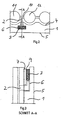
- Fig. 1 shows the tube wall plate 1, which has the recess 6. These Pipe wall plate 1 is hung on the steel part 2 during assembly. in this connection penetrates the steel part 2 with its hook in the recess 6 of Tube wall plate 1 a.
- the tube wall plate 1 has the back 4 and front 5.
- the Recess 6 ends at the back 4 with the opening 8 and at the upper side surface 7 with the opening. 9
- the cross section of the opening 9 of Recess 6 rectangular and thus is also the cross section of the molding. 3 rectangular. If the opening area has a different shape, the Molded part formed in the then present form.
- the molded part 3 is made of a material which in its chemical and physical properties the material of Tube wall plate 1 corresponds, voltages are avoided, which are among the described destruction and cracks.
- FIG. 3 the section A-A shown in FIG. 2 is shown.
- the steel part 2 protrudes into the recess 6 of the tube wall plate 1 a. It is evident that the Recess 6 ends at the upper side surface 7 with the opening 9.
- This opening 9 of the recess 6 is the molded part 3 is inserted.
- the Molded part 3 projects into the recess 6. By inserting the molded part 3 in the recess 6, this was accurately closed.
- the molded part 3 acts as a "cork" for this recess. 6
Landscapes
- Engineering & Computer Science (AREA)
- Mechanical Engineering (AREA)
- General Engineering & Computer Science (AREA)
- Chemical & Material Sciences (AREA)
- Combustion & Propulsion (AREA)
- Cultivation Receptacles Or Flower-Pots, Or Pots For Seedlings (AREA)
- Furnace Housings, Linings, Walls, And Ceilings (AREA)
Abstract
Description
- Fig. 1
- Die Explosionszeichnung einer Rohrwandplatte, eines Formteils und eines Stahlteils,
- Fig. 2
- den Querschnitt durch eine Rohrwandplatte, die an einer Rohrwand befestigt ist, und
- Fig. 3
- den Schnitt A-A gemäß Fig. 2.
Claims (7)
- Rohrwandplatte mit mindestens einer Ausnehmung,
dadurch gekennzeichnet, dass ein Formteil (3) in die Ausnehmung (6) der Rohrwandplatte (1) einsetzbar ausgebildet ist. - Rohrwandplatte nach Anspruch 1,
dadurch gekennzeichnet, dass das Material des Formteiles (3) in seinen physikalischen und chemischen Eigenschaften dem Material der Rohrwandplatte (1) entspricht. - Rohrwandplatte nach Anspruch 1 oder 2,
dadurch gekennzeichnet, dass der Querschnitt des Formteiles (3) dem Querschnitt der Öffnung (9) der Ausnehmung (6) entspricht. - Rohrwandplatte nach Anspruch 1, 2 oder 3,
dadurch gekennzeichnet, dass das Formteil (3) die Öffnung (9) der Ausnehmung (6) der Rohrwandplatte (1) nach der Montage passgenau verschließt. - Rohrwandplatte nach einem der vorherigen Ansprüche,
dadurch gekennzeichnet, dass das Formteil (3) in die Öffnung (9) der Ausnehmung (6) der Rohrwandplatte (1) bei der Montage gesteckt, geklebt oder gemörtelt wird. - Rohrwandplatte nach einem der vorherigen Ansprüche,
dadurch gekennzeichnet, dass die Ausnehmung (6) der Rohrwandplatte (1) an der oberen Seitenfläche (7) mit der Öffnung (9) endet, in die das Formteil (3) eingesetzt wird, und
dass das Formteil (3) in die Ausnehmung (6) der Rohrwandplatte (1) ragt. - Feuerfestabkleidung, insbesondere für Müllverbrennungsanlagen, mit mehreren neben- und übereinander angeordneten Rohrwandplatten nach einem der Ansprüche 1 bis 6.
Applications Claiming Priority (2)
| Application Number | Priority Date | Filing Date | Title |
|---|---|---|---|
| DE102004020090 | 2004-04-24 | ||
| DE102004020090 | 2004-04-24 |
Publications (2)
| Publication Number | Publication Date |
|---|---|
| EP1589284A2 true EP1589284A2 (de) | 2005-10-26 |
| EP1589284A3 EP1589284A3 (de) | 2010-09-01 |
Family
ID=34934721
Family Applications (1)
| Application Number | Title | Priority Date | Filing Date |
|---|---|---|---|
| EP05007253A Withdrawn EP1589284A3 (de) | 2004-04-24 | 2005-04-02 | Rohrwandplatte mit mindestens einer Ausnehmung und Feuerfestabkleidung |
Country Status (1)
| Country | Link |
|---|---|
| EP (1) | EP1589284A3 (de) |
Cited By (1)
| Publication number | Priority date | Publication date | Assignee | Title |
|---|---|---|---|---|
| EP2302315A1 (de) * | 2009-08-31 | 2011-03-30 | Saint-Gobain Industriekeramik Düsseldorf GmbH | Korrosionsschutzkörper |
Family Cites Families (4)
| Publication number | Priority date | Publication date | Assignee | Title |
|---|---|---|---|---|
| GB311593A (en) * | 1928-07-10 | 1929-05-16 | R & W Hawthorn Leslie & Compan | Improvements in or relating to furnace firebrick fittings |
| FR2628520A1 (fr) * | 1988-03-14 | 1989-09-15 | Vilia V | Procede de fixation d'un bloc de construction en un materiau refractaire sur une ossature, dans le domaine de la thermique industrielle |
| DE29504758U1 (de) * | 1995-03-21 | 1995-05-18 | Carborundum Deutschland GmbH, 40597 Düsseldorf | Schraubbefestigung für keramische Platten |
| US6412548B1 (en) * | 1997-11-28 | 2002-07-02 | Mitsubishi Heavy Industries, Ltd. | Water tube protective refractory structure and method of assembling the same |
-
2005
- 2005-04-02 EP EP05007253A patent/EP1589284A3/de not_active Withdrawn
Cited By (1)
| Publication number | Priority date | Publication date | Assignee | Title |
|---|---|---|---|---|
| EP2302315A1 (de) * | 2009-08-31 | 2011-03-30 | Saint-Gobain Industriekeramik Düsseldorf GmbH | Korrosionsschutzkörper |
Also Published As
| Publication number | Publication date |
|---|---|
| EP1589284A3 (de) | 2010-09-01 |
Similar Documents
| Publication | Publication Date | Title |
|---|---|---|
| DE8231578U1 (de) | Feuerfeste auskleidungsmatte aus fasermaterial mit befestigungseinrichtungen zur befestigung an einer wand oder dergleichen | |
| DE3008659C2 (de) | Feuersicheres Glasfenster | |
| EP2189743B1 (de) | Wärmedämmende Auskleidung von Industrieöfen | |
| DE2454202A1 (de) | Rostplatte fuer rostkuehler | |
| DE10303173B4 (de) | Rohrwandschutz für eine Kesselrohrwand | |
| DE202009007311U1 (de) | Lärmschutzelement | |
| EP0388774B1 (de) | Feuerschutztür | |
| DE3883157T2 (de) | Auskleidungsbauteil und sein aufbau für öfen zur wärmebehandlung. | |
| DE102008033219A1 (de) | Feuerfestes Rohrwandverkleidung sowie Halteelement für eine feuerfeste Rohrwandverkleidung | |
| DE202009015428U1 (de) | Fassaden-Wärmeschutzplatte | |
| CH615724A5 (en) | Self-supporting wall element for producing internal and external walls in building construction | |
| DE9310405U1 (de) | Kabelkanal und Kanalelement für einen solchen Kanal | |
| DE102009010557A1 (de) | Fassadenelement | |
| DE3317266A1 (de) | Fang, insbesondere rauchfang, sowie formstein zur herstellung desselben | |
| EP1336808A1 (de) | Feuerfestabkleidung | |
| DE2322913A1 (de) | Kombiniertes zu- und abluftventil | |
| EP1577625A1 (de) | Feuerfestabkleidung | |
| DE102007054761B4 (de) | Gasverteilerplatte für eine Heizkammer eines Ofens | |
| EP1681430A2 (de) | Verbundprofiil für Rahmen von Wandelementen, Türen und Fenstern | |
| DE3437022A1 (de) | Kaminelement | |
| EP3260173A1 (de) | Brandschutzelement | |
| DE2212193A1 (de) | Anschlussformstueck fuer reinigungsund kontrolltueren fuer kamine | |
| EP0476275A1 (de) | Spülsteinanordnung | |
| AT241755B (de) | Öffnungsverschluß für Öfen und Heizkessel | |
| AT350426B (de) | Tuerschloss mit einem stulp und einem mit diesem verbundenen gehaeuse |
Legal Events
| Date | Code | Title | Description |
|---|---|---|---|
| PUAI | Public reference made under article 153(3) epc to a published international application that has entered the european phase |
Free format text: ORIGINAL CODE: 0009012 |
|
| AK | Designated contracting states |
Kind code of ref document: A2 Designated state(s): AT BE BG CH CY CZ DE DK EE ES FI FR GB GR HU IE IS IT LI LT LU MC NL PL PT RO SE SI SK TR |
|
| AX | Request for extension of the european patent |
Extension state: AL BA HR LV MK YU |
|
| PUAL | Search report despatched |
Free format text: ORIGINAL CODE: 0009013 |
|
| AK | Designated contracting states |
Kind code of ref document: A3 Designated state(s): AT BE BG CH CY CZ DE DK EE ES FI FR GB GR HU IE IS IT LI LT LU MC NL PL PT RO SE SI SK TR |
|
| AX | Request for extension of the european patent |
Extension state: AL BA HR LV MK YU |
|
| RIC1 | Information provided on ipc code assigned before grant |
Ipc: F27D 1/12 20060101ALI20100723BHEP Ipc: F23M 5/08 20060101ALI20100723BHEP Ipc: F23M 5/04 20060101ALI20100723BHEP Ipc: F23M 5/02 20060101AFI20050907BHEP |
|
| AKY | No designation fees paid | ||
| STAA | Information on the status of an ep patent application or granted ep patent |
Free format text: STATUS: THE APPLICATION IS DEEMED TO BE WITHDRAWN |
|
| 18D | Application deemed to be withdrawn |
Effective date: 20110302 |