EP1587599B1 - Additivabgabepatrone für einen ölfilter und diese enthaltender ölfilter - Google Patents
Additivabgabepatrone für einen ölfilter und diese enthaltender ölfilter Download PDFInfo
- Publication number
- EP1587599B1 EP1587599B1 EP04705317A EP04705317A EP1587599B1 EP 1587599 B1 EP1587599 B1 EP 1587599B1 EP 04705317 A EP04705317 A EP 04705317A EP 04705317 A EP04705317 A EP 04705317A EP 1587599 B1 EP1587599 B1 EP 1587599B1
- Authority
- EP
- European Patent Office
- Prior art keywords
- additive
- oil
- cartridge
- chamber
- housing
- Prior art date
- Legal status (The legal status is an assumption and is not a legal conclusion. Google has not performed a legal analysis and makes no representation as to the accuracy of the status listed.)
- Expired - Lifetime
Links
- 239000000654 additive Substances 0.000 title claims abstract description 113
- 230000000996 additive effect Effects 0.000 title claims abstract description 93
- 230000009286 beneficial effect Effects 0.000 claims abstract description 18
- 239000012530 fluid Substances 0.000 claims abstract description 14
- 239000003795 chemical substances by application Substances 0.000 claims abstract description 4
- 239000003921 oil Substances 0.000 claims description 82
- 239000000203 mixture Substances 0.000 claims description 30
- 238000004891 communication Methods 0.000 claims description 7
- KWYUFKZDYYNOTN-UHFFFAOYSA-M Potassium hydroxide Chemical compound [OH-].[K+] KWYUFKZDYYNOTN-UHFFFAOYSA-M 0.000 claims description 6
- HEMHJVSKTPXQMS-UHFFFAOYSA-M Sodium hydroxide Chemical compound [OH-].[Na+] HEMHJVSKTPXQMS-UHFFFAOYSA-M 0.000 claims description 6
- 239000003599 detergent Substances 0.000 claims description 5
- 239000002270 dispersing agent Substances 0.000 claims description 5
- VTYYLEPIZMXCLO-UHFFFAOYSA-L Calcium carbonate Chemical compound [Ca+2].[O-]C([O-])=O VTYYLEPIZMXCLO-UHFFFAOYSA-L 0.000 claims description 4
- CDBYLPFSWZWCQE-UHFFFAOYSA-L Sodium Carbonate Chemical compound [Na+].[Na+].[O-]C([O-])=O CDBYLPFSWZWCQE-UHFFFAOYSA-L 0.000 claims description 4
- XLOMVQKBTHCTTD-UHFFFAOYSA-N Zinc monoxide Chemical compound [Zn]=O XLOMVQKBTHCTTD-UHFFFAOYSA-N 0.000 claims description 4
- BWHMMNNQKKPAPP-UHFFFAOYSA-L potassium carbonate Chemical compound [K+].[K+].[O-]C([O-])=O BWHMMNNQKKPAPP-UHFFFAOYSA-L 0.000 claims description 4
- 239000005069 Extreme pressure additive Substances 0.000 claims description 3
- 150000001447 alkali salts Chemical class 0.000 claims description 3
- 239000003963 antioxidant agent Substances 0.000 claims description 3
- 238000005260 corrosion Methods 0.000 claims description 3
- 230000007797 corrosion Effects 0.000 claims description 3
- 239000003112 inhibitor Substances 0.000 claims description 3
- 239000003607 modifier Substances 0.000 claims description 3
- UIIMBOGNXHQVGW-DEQYMQKBSA-M Sodium bicarbonate-14C Chemical compound [Na+].O[14C]([O-])=O UIIMBOGNXHQVGW-DEQYMQKBSA-M 0.000 claims description 2
- 229910052782 aluminium Inorganic materials 0.000 claims description 2
- XAGFODPZIPBFFR-UHFFFAOYSA-N aluminium Chemical compound [Al] XAGFODPZIPBFFR-UHFFFAOYSA-N 0.000 claims description 2
- 235000010210 aluminium Nutrition 0.000 claims description 2
- 229910000019 calcium carbonate Inorganic materials 0.000 claims description 2
- 235000010216 calcium carbonate Nutrition 0.000 claims description 2
- AXCZMVOFGPJBDE-UHFFFAOYSA-L calcium dihydroxide Chemical compound [OH-].[OH-].[Ca+2] AXCZMVOFGPJBDE-UHFFFAOYSA-L 0.000 claims description 2
- 239000000920 calcium hydroxide Substances 0.000 claims description 2
- 229910001861 calcium hydroxide Inorganic materials 0.000 claims description 2
- ZLNQQNXFFQJAID-UHFFFAOYSA-L magnesium carbonate Chemical compound [Mg+2].[O-]C([O-])=O ZLNQQNXFFQJAID-UHFFFAOYSA-L 0.000 claims description 2
- 239000001095 magnesium carbonate Substances 0.000 claims description 2
- 229910000021 magnesium carbonate Inorganic materials 0.000 claims description 2
- 239000000395 magnesium oxide Substances 0.000 claims description 2
- CPLXHLVBOLITMK-UHFFFAOYSA-N magnesium oxide Inorganic materials [Mg]=O CPLXHLVBOLITMK-UHFFFAOYSA-N 0.000 claims description 2
- AXZKOIWUVFPNLO-UHFFFAOYSA-N magnesium;oxygen(2-) Chemical compound [O-2].[Mg+2] AXZKOIWUVFPNLO-UHFFFAOYSA-N 0.000 claims description 2
- 239000006078 metal deactivator Substances 0.000 claims description 2
- 239000011736 potassium bicarbonate Substances 0.000 claims description 2
- 229910000028 potassium bicarbonate Inorganic materials 0.000 claims description 2
- 235000015497 potassium bicarbonate Nutrition 0.000 claims description 2
- 229910000027 potassium carbonate Inorganic materials 0.000 claims description 2
- 235000011181 potassium carbonates Nutrition 0.000 claims description 2
- TYJJADVDDVDEDZ-UHFFFAOYSA-M potassium hydrogencarbonate Chemical compound [K+].OC([O-])=O TYJJADVDDVDEDZ-UHFFFAOYSA-M 0.000 claims description 2
- 229910000029 sodium carbonate Inorganic materials 0.000 claims description 2
- 239000003381 stabilizer Substances 0.000 claims description 2
- 239000011787 zinc oxide Substances 0.000 claims description 2
- 230000004888 barrier function Effects 0.000 claims 2
- 230000000903 blocking effect Effects 0.000 claims 1
- 238000002485 combustion reaction Methods 0.000 abstract description 13
- 239000007787 solid Substances 0.000 abstract description 11
- 239000008188 pellet Substances 0.000 abstract description 6
- 238000001914 filtration Methods 0.000 abstract description 5
- 238000009434 installation Methods 0.000 abstract description 2
- 239000010687 lubricating oil Substances 0.000 description 15
- 238000000034 method Methods 0.000 description 9
- 239000002253 acid Substances 0.000 description 6
- 239000002245 particle Substances 0.000 description 6
- 239000010802 sludge Substances 0.000 description 6
- 150000007513 acids Chemical class 0.000 description 5
- 239000000463 material Substances 0.000 description 5
- 239000010705 motor oil Substances 0.000 description 4
- 230000000717 retained effect Effects 0.000 description 4
- 230000002378 acidificating effect Effects 0.000 description 3
- 239000012141 concentrate Substances 0.000 description 3
- 239000000356 contaminant Substances 0.000 description 3
- 239000004071 soot Substances 0.000 description 3
- 239000000126 substance Substances 0.000 description 3
- OKTJSMMVPCPJKN-UHFFFAOYSA-N Carbon Chemical compound [C] OKTJSMMVPCPJKN-UHFFFAOYSA-N 0.000 description 2
- 150000001875 compounds Chemical class 0.000 description 2
- 230000003750 conditioning effect Effects 0.000 description 2
- 238000007796 conventional method Methods 0.000 description 2
- -1 e.g. Polymers 0.000 description 2
- 230000003716 rejuvenation Effects 0.000 description 2
- 239000000758 substrate Substances 0.000 description 2
- 229910000831 Steel Inorganic materials 0.000 description 1
- HCHKCACWOHOZIP-UHFFFAOYSA-N Zinc Chemical compound [Zn] HCHKCACWOHOZIP-UHFFFAOYSA-N 0.000 description 1
- 238000005054 agglomeration Methods 0.000 description 1
- 230000002776 aggregation Effects 0.000 description 1
- 239000012298 atmosphere Substances 0.000 description 1
- 239000011230 binding agent Substances 0.000 description 1
- 230000015572 biosynthetic process Effects 0.000 description 1
- 239000002131 composite material Substances 0.000 description 1
- 239000002826 coolant Substances 0.000 description 1
- 238000009792 diffusion process Methods 0.000 description 1
- 238000004090 dissolution Methods 0.000 description 1
- 230000000694 effects Effects 0.000 description 1
- 238000001125 extrusion Methods 0.000 description 1
- 238000009472 formulation Methods 0.000 description 1
- 239000002803 fossil fuel Substances 0.000 description 1
- 239000000446 fuel Substances 0.000 description 1
- 239000002816 fuel additive Substances 0.000 description 1
- 239000004519 grease Substances 0.000 description 1
- 239000012535 impurity Substances 0.000 description 1
- 239000007788 liquid Substances 0.000 description 1
- 239000000314 lubricant Substances 0.000 description 1
- 229910052751 metal Inorganic materials 0.000 description 1
- 239000002184 metal Substances 0.000 description 1
- 150000002739 metals Chemical class 0.000 description 1
- 238000002156 mixing Methods 0.000 description 1
- 238000006386 neutralization reaction Methods 0.000 description 1
- 230000003472 neutralizing effect Effects 0.000 description 1
- 230000037074 physically active Effects 0.000 description 1
- 239000004033 plastic Substances 0.000 description 1
- 229920003023 plastic Polymers 0.000 description 1
- 229920006324 polyoxymethylene Polymers 0.000 description 1
- 239000002243 precursor Substances 0.000 description 1
- 150000003839 salts Chemical class 0.000 description 1
- 238000012216 screening Methods 0.000 description 1
- 239000010959 steel Substances 0.000 description 1
- 230000000153 supplemental effect Effects 0.000 description 1
- 229920001169 thermoplastic Polymers 0.000 description 1
- 239000004416 thermosoftening plastic Substances 0.000 description 1
- 239000002966 varnish Substances 0.000 description 1
- 239000011701 zinc Substances 0.000 description 1
- 229910052725 zinc Inorganic materials 0.000 description 1
Images


Classifications
-
- B—PERFORMING OPERATIONS; TRANSPORTING
- B01—PHYSICAL OR CHEMICAL PROCESSES OR APPARATUS IN GENERAL
- B01D—SEPARATION
- B01D27/00—Cartridge filters of the throw-away type
- B01D27/02—Cartridge filters of the throw-away type with cartridges made from a mass of loose granular or fibrous material
-
- B—PERFORMING OPERATIONS; TRANSPORTING
- B01—PHYSICAL OR CHEMICAL PROCESSES OR APPARATUS IN GENERAL
- B01D—SEPARATION
- B01D37/00—Processes of filtration
- B01D37/02—Precoating the filter medium; Addition of filter aids to the liquid being filtered
-
- B—PERFORMING OPERATIONS; TRANSPORTING
- B01—PHYSICAL OR CHEMICAL PROCESSES OR APPARATUS IN GENERAL
- B01D—SEPARATION
- B01D37/00—Processes of filtration
- B01D37/02—Precoating the filter medium; Addition of filter aids to the liquid being filtered
- B01D37/025—Precoating the filter medium; Addition of filter aids to the liquid being filtered additives incorporated in the filter
-
- C—CHEMISTRY; METALLURGY
- C10—PETROLEUM, GAS OR COKE INDUSTRIES; TECHNICAL GASES CONTAINING CARBON MONOXIDE; FUELS; LUBRICANTS; PEAT
- C10M—LUBRICATING COMPOSITIONS; USE OF CHEMICAL SUBSTANCES EITHER ALONE OR AS LUBRICATING INGREDIENTS IN A LUBRICATING COMPOSITION
- C10M175/00—Working-up used lubricants to recover useful products ; Cleaning
- C10M175/0091—Treatment of oils in a continuous lubricating circuit (e.g. motor oil system)
-
- F—MECHANICAL ENGINEERING; LIGHTING; HEATING; WEAPONS; BLASTING
- F01—MACHINES OR ENGINES IN GENERAL; ENGINE PLANTS IN GENERAL; STEAM ENGINES
- F01M—LUBRICATING OF MACHINES OR ENGINES IN GENERAL; LUBRICATING INTERNAL COMBUSTION ENGINES; CRANKCASE VENTILATING
- F01M11/00—Component parts, details or accessories, not provided for in, or of interest apart from, groups F01M1/00 - F01M9/00
- F01M11/03—Mounting or connecting of lubricant purifying means relative to the machine or engine; Details of lubricant purifying means
-
- F—MECHANICAL ENGINEERING; LIGHTING; HEATING; WEAPONS; BLASTING
- F01—MACHINES OR ENGINES IN GENERAL; ENGINE PLANTS IN GENERAL; STEAM ENGINES
- F01M—LUBRICATING OF MACHINES OR ENGINES IN GENERAL; LUBRICATING INTERNAL COMBUSTION ENGINES; CRANKCASE VENTILATING
- F01M1/00—Pressure lubrication
- F01M1/10—Lubricating systems characterised by the provision therein of lubricant venting or purifying means, e.g. of filters
- F01M2001/1007—Lubricating systems characterised by the provision therein of lubricant venting or purifying means, e.g. of filters characterised by the purification means combined with other functions
- F01M2001/1014—Lubricating systems characterised by the provision therein of lubricant venting or purifying means, e.g. of filters characterised by the purification means combined with other functions comprising supply of additives
-
- F—MECHANICAL ENGINEERING; LIGHTING; HEATING; WEAPONS; BLASTING
- F01—MACHINES OR ENGINES IN GENERAL; ENGINE PLANTS IN GENERAL; STEAM ENGINES
- F01M—LUBRICATING OF MACHINES OR ENGINES IN GENERAL; LUBRICATING INTERNAL COMBUSTION ENGINES; CRANKCASE VENTILATING
- F01M9/00—Lubrication means having pertinent characteristics not provided for in, or of interest apart from, groups F01M1/00 - F01M7/00
- F01M9/02—Lubrication means having pertinent characteristics not provided for in, or of interest apart from, groups F01M1/00 - F01M7/00 having means for introducing additives to lubricant
-
- Y—GENERAL TAGGING OF NEW TECHNOLOGICAL DEVELOPMENTS; GENERAL TAGGING OF CROSS-SECTIONAL TECHNOLOGIES SPANNING OVER SEVERAL SECTIONS OF THE IPC; TECHNICAL SUBJECTS COVERED BY FORMER USPC CROSS-REFERENCE ART COLLECTIONS [XRACs] AND DIGESTS
- Y10—TECHNICAL SUBJECTS COVERED BY FORMER USPC
- Y10S—TECHNICAL SUBJECTS COVERED BY FORMER USPC CROSS-REFERENCE ART COLLECTIONS [XRACs] AND DIGESTS
- Y10S210/00—Liquid purification or separation
- Y10S210/17—Twist-on
Definitions
- the present invention relates to an additive dispensing cartridge for an oil filter assembly, and to an oil filter incorporating the cartridge. More particularly, the present invention relates to an additive dispensing cartridge containing a beneficial additive composition, and to an oil filter having a centrally located additive dispenser incorporated therein. Even more particularly, the present invention relates to an oil filter in which a centrally located additive dispenser, containing one or more oil-conditioning compounds therein, is operable to slowly release the oil conditioning compounds, over time, into filtered engine oil on the downstream, or 'clean' side of the mechanical filter element.
- contaminants include, among others, soot, which is formed from incomplete combustion of the fossil fuel, and acids that result from combustion. These contaminants are typically introduced into the lubricating oil during engine operation, and tend to increase oil viscosity and generate unwanted engine deposits, leading to increased engine wear.
- TBN total base number
- conventional lubricating oils often include one or more further additives, which may be corrosion inhibitors, antioxidants, friction modifiers, pour point depressants, detergents, viscosity index improvers, anti-wear agents, and/or extreme pressure additives.
- further additives may be beneficial; however, with conventional methods, the amount and concentration of these additives are limited by the ability of lubricating oils to suspend these additives, as well as by the chemical stability of these additives in the oil.
- oil filters which include extra additives for the oil include U.S. patents 4,075,097 , 4,144,169 , 5,591,330 , 5,725,031 , and 6,045,692 .
- Brownawell patents provide for the inclusion of particles in an oil filter that are oil insoluble and oil wettable, and which complex with sludge, such that at least some of the sludge that these particles come into contact with is immobilized on the particles.
- the Brownawell 617 patent discloses the inclusion of oil insoluble and oil wettable particles in an oil filter that are retained on a divided substrate, whereas the Brownawell '463 patent discloses the inclusion of such particles that are not retained on a substrate, but are nonetheless retained in the oil filter.
- U.S. patent number 5,225,081 to Brownawell discloses method of removing polynuclear aromatics from used lubricating oil.
- the method of the Brownawell '081 reference involves passing oil through a staged oil filter system, which may include a chemically active filter media.
- the chemically active filter media is made of a composite material including particles of an active component and a thermoplastic binder, which are a product of a heated extrusion process.
- Basic conditioners are given as one example of materials suitable for use as chemically active filter media.
- Activated carbon is also emphasized as a preferred component of the filter media in this reference.
- U.S. patent numbers 4,557,829 and 4,886,599 discloses a filter cartridge with sequential concentric cylindrical filter elements, for both chemical and mechanical filtration of oil contained in an oil-sealed vacuum pump.
- U.S. patent 6,238,554 to Martin, Jr. et al discloses a fuel filter including an inner housing assembly containing a soluble fuel additive composition.
- the present invention provides an improved oil filter, having a basic conditioner and/or another beneficial additive incorporated therein.
- the beneficial additive is housed within a centrally located additive dispenser cartridge, which is operable to dispense an additive composition into relatively clean filtered oil that has already passed through a mechanical filter element.
- an oil filter as defined in claim 1.
- an additive cartridge for an oil filter as defined in claim 8.
- the additive chamber includes an additive cartridge which is a hollow shell, and a beneficial additive contained within the housing.
- the additive chamber is located inside of the mechanical filter element at a central part of the filter, so that the oil has already been mechanically filtered when additive is added thereto.
- the apparatus according to the invention may also include a baffle for directing oil flow, and the additive cartridge may be attached to the baffle. Where the baffle is used, the dividing wall is provided between the baffle and the additive chamber.
- the additive cartridge has at least one opening, and may have a limited number of openings therein to control the rate of diffusion therefrom.
- an object of the present invention to provide an improved oil filter including one or more beneficial oil additives that are released slowly over the life of the filter.
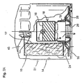
- FIG. 1 and 2A there is shown an oil filter 20 according to a first preferred embodiment of this invention.
- the direction of oil flow, through the filter 20, is shown by the arrows in Figure 2A, which illustrate a flow path through the filter.
- the oil filter 20 generally includes a hollow cylindrical housing 22 which defines a hollow chamber 14 therein, a porous, mechanical filter element 15 within that chamber, and a centrally located additive cartridge 18, also retained inside the housing chamber 14.
- the housing 22 includes a hollow, generally cylindrical case 21, and a base plate 24 sealingly attached to the case.
- a foraminous center tube 17 may, optionally, be provided within the filter housing 22 to supportively reinforce the mechanical filter element 15 thereon.
- An anti-drainback valve 19 is provided inside the filter housing 22, at the base of the center tube 17, to keep oil in the filter 20 during engine shutoff, when the filter is mounted in the orientation shown in Figure 2.
- the oil filter 20 may incorporate a spring-loaded pressure relief valve of a type known to those in the art.
- a retainer 45 may be provided above the center tube 17, to exert a downward pressure thereon.
- the housing base plate 24 includes a plurality of inlet ports 28 formed therethrough and arranged in a circular pattern.
- the base plate 24 also includes a central outlet port 26.
- the outlet port 26 has a plurality of female threads formed therein, to allow rotatable mounting of the filter 20 on an externally threaded hollow tubular fitting on an engine block (not shown).
- An annular external seal or gasket 33 ( Figure 1) fits engagingly into a groove 30 formed at the bottom surface of the base plate, to resist oil leakage outwardly from the base of the filter.
- the mechanical filter element 15 includes a conventional cylindrical member made of accordion-pleated filter paper.
- the filter 20 contains an additive cartridge 18 disposed centrally and coaxially inside of the center tube 17, in the middle of the mechanical filter element 15.
- the additive cartridge 18 includes a hollow cartridge shell 35, provided in a generally cylindrical shape, closed at the top and open at the bottom thereof in the orientation shown.
- the additive cartridge 18 also includes a solid additive composition 16 inside of the cartridge shell 35.
- the hollow cartridge shell 35 has a cylindrical side wall 36 with a plurality of apertures 37 formed in a lower portion thereof.
- the cartridge shell 35 also includes a cap 38, which covers the top of the side wall 36 and is integrally formed therewith.
- the cartridge shell 35 also includes a horizontal dividing wall 39 extending across a part of the side wall 36 above the apertures 37.
- the dividing wall 39 subdivides the shell 35 into two sections, a lower baffle portion 40 and an upper dispenser housing 41 containing a hollow storage chamber 42 therein.
- the cartridge shell 35 has at least one opening 25 formed therethrough to allow fluid communication between the storage chamber 42 and the exterior of the cartridge.
- the opening(s) may be formed in the side wall 36, the cap 38, and/or the dividing wall 39.
- the number and size of the opening(s) 25 may be selected to control the rate of dissolution of the additive material 16 from the dispenser housing 41 for a particular application.
- the additive cartridge 35 also has a horizontal flange 44 extending transversely outwardly from the side wall 36 at the base of the baffle 40.
- the flange 44 may be included to cooperate with the anti-drainback valve 19, to help seal against fluid bypassing the mechanical filter 15 under normal operation conditions.
- the additive cartridge 18 is preferred to be located in the flow path downstream of the mechanical filter element 15, in order to allow the beneficial additive composition thereof to be released into the oil on the clean side of the filter element, after mechanical filtration has been achieved.
- the additive cartridge 18 contains a beneficial additive composition therein, which may be a solid block 16, as shown in Figure 2A.
- the additive composition 16 may be solid at standard temperature and pressure, defined as 25 degrees C and one atmosphere pressure.
- the additive composition 16 may be injected into the cartridge shell 35 in a hot liquid state, and allowed to solidify as it cools.
- the additive composition 16 may be added in powdered form, or may be dispersed in a grease or wax.
- the additive composition 16 is preferred to be at least partially soluble in hot engine oil.
- the additive composition 16 includes one or more additives which may be selected from the group including basic conditioners, corrosion inhibitors, metal deactivators, antioxidants, dispersants, friction modifiers, oil stabilizers, pour point depressants, detergents, viscosity index improvers, anti-wear agents, extreme pressure additives, mixtures of the above additives, and/or other known beneficial additives.
- additives which may be selected from the group including basic conditioners, corrosion inhibitors, metal deactivators, antioxidants, dispersants, friction modifiers, oil stabilizers, pour point depressants, detergents, viscosity index improvers, anti-wear agents, extreme pressure additives, mixtures of the above additives, and/or other known beneficial additives.
- the basic conditioner of the additive cartridge is preferably a basic salt selected from the group consisting of calcium carbonate, potassium carbonate, potassium bicarbonate, aluminum dihydroxy sodium carbonate, magnesium oxide, magnesium carbonate, zinc oxide, sodium bicarbonate, sodium hydroxide, calcium hydroxide, potassium hydroxide, and mixtures thereof.
- the material selected for the cartridge shell 35 is preferred to be a material which remains stable in a hot oil environment.
- Preferred materials are metals such as steel and oil-tolerant plastics such as, e.g., polyacetals.
- the cartridge 18 allows the beneficial additive composition 16 to be slowly released into the oil, thereby conditioning the oil in a metered manner over time.
- the concentrated additive composition in the cartridge 18 may be provided as a plurality of separate individual pellets 48, in order to provide greater surface area than is afforded with the solid additive block 16 of Figure 2A.
- pellets 48 are used, they may be disassociated and separate from one another.
- the individual additive-dispensing pellets 48 housed within the cartridge shell 35 may be bonded together or otherwise cohesively associated with one another to form a substantially integral, yet highly porous structure capable of independent self-support. Where the pellets 48 are joined together in this way, the cartridge shell 35 is not required, and may be omitted if desired.
- the basic salt component of the additive 16 acts to counteract and neutralize acidic combustion products. This neutralization of acidic combustion products allows for a much longer useful life of some other oil additives such as, for example, dispersants and zinc dialkyldithiophosphate (ZDP), which are provided in the oil by the manufacturer thereof. This, in turn, allows for greater intervals between oil changes than is possible without the chemically active filter element.
- ZDP zinc dialkyldithiophosphate
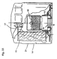
- the cartridge 218 includes a hollow cartridge shell 235 in the form of a basket.
- the shell 235 is either supported by or otherwise attached to the center tube 217. While the center tube 217 is shown in simplified form in the drawings, it will be understood that it is a porous member.
- the shell 235 may include a top flange 219 for connecting to the center tube.
- the shell 235 has a recessed space formed in the top thereof for supportively receiving a retainer spring 245.
- the shell 235 also has one or more openings 225 formed therein to allow fluid communication with between the interior thereof and the space surrounding the shell:
- a solid additive concentrate 216 is provided inside of the shell 235, in a manner similar to that described above for the first embodiment.
- the additive may be in one piece or may be pelletized.
- the cartridge 318 is a modified center tube.
- the cartridge 318 includes a hollow cylindrical shell 335 with a solid additive 316 contained therein.
- the shell 235 also has one or more openings 325 formed therein to allow fluid communication with between the interior thereof and the space surrounding the shell.
- a solid additive concentrate 316 is provided inside of the shell 235, in a manner similar to that described above for the first embodiment.
- the additive may be in one piece or may be pelletized.
Landscapes
- Chemical & Material Sciences (AREA)
- Chemical Kinetics & Catalysis (AREA)
- Engineering & Computer Science (AREA)
- Combustion & Propulsion (AREA)
- General Chemical & Material Sciences (AREA)
- Oil, Petroleum & Natural Gas (AREA)
- Organic Chemistry (AREA)
- Lubrication Details And Ventilation Of Internal Combustion Engines (AREA)
- Filtration Of Liquid (AREA)
- Lubricants (AREA)
- Fats And Perfumes (AREA)
Claims (10)
- Ölfilter (20), der Folgendes aufweist:ein Gehäuse (22) mit einem Einlass (28) und einem Auslass (26) eines Strömungspfades durch eine Kammer (14) hindurch, die durch das Gehäuse definiert wird,ein mechanisch aktives Filterelement (15), das im Inneren des Filtergehäuses (22) in dem Strömungspfad angeordnet ist, undeine Additivpatrone (18), die im Inneren des Filtergehäuses (22) und im Inneren des mechanisch aktiven Filterelements (15) angeordnet ist,eine Öladditivzusammensetzung, die innerhalb der Additivpatrone angeordnet ist, dadurch gekennzeichnet, dass die Additivpatrone (18) Folgendes aufweist:wobei das Abgabegehäuse einen Abschnitt des Strömungspfades von dem Einlass (28) zu dem Auslass (26) definiert, undein Abgabegehäuse (35) mit einer Seitenwand (36), die einen Umfangsrand einer ersten Kammer und einer zweiten Kammer (41) definiert, und mit einer Trennwand (39), die sich von der Seitenwand erstreckt, um eine Sperre zwischen der ersten Kammer und der zweiten Kammer innerhalb des Abgabegehäuses zu definieren, wobei die erste Kammer mehrere erste Öffnungen (37) aufweist, die in der Seitenwand ausgebildet sind und eine Strömungsverbindung zwischen dem Strömungspfad und dem Auslass (26) ermöglichen, wobei die zweite Kammer eine Additivspeicherkammer (42) definiert und eine Ölzusammensetzung enthält, wobei die zweite Kammer mehrere zweite Öffnungen (25) aufweist, die in der Seitenwand ausgebildet sind und eine Strömungsverbindung von wenigstens einem Teil eines Abschnitts des Strömungspfades mit der darin enthaltenen Öladditivzusammensetzung ermöglichen,
wobei die Trennwand (39) einen Abschnitt des Strömungspfades durch das Abgabegehäuse hindurch zu dem Auslass von der Öladditivzusammensetzung in der zweiten Kammer (42) trennt. - Ölfilter nach Anspruch 1, wobei die Additivpatrone (18) im Wesentlichen mittig in dem Filtergehäuse (22) angeordnet ist.
- Ölfilter nach Anspruch 1 oder Anspruch 2, wobei die Additivpatrone (18) eine zylindrische Röhre aufweist.
- Ölfilter nach einem der Ansprüche 1 bis 3, wobei der Flanschabschnitt (44) das Abgabegehäuse (35) an einem ersten Ende des Gehäuses stützt und das Gehäuse des Weiteren eine Basisplatte (24) aufweist, die an dem ersten Ende angeordnet ist, wobei die Basisplatte (24) mehrere Einlassöffnungen und eine Auslassöffnung aufweist, um den Einlass (28) und den Auslass (26) des Gehäuses zu definieren.
- Ölfilter nach einem der Ansprüche 1 bis 3, wobei der Flanschabschnitt (44) das Abgabegehäuse (35) an einem ersten Ende des Gehäuses stützt und das Gehäuse des Weiteren eine Basisplatte (24) aufweist, die an dem ersten Ende angeordnet ist, wobei die Basisplatte mehrere Einlassöffnungen und eine Auslassöffnung aufweist, um den Einlass (28) und den Auslass (26) des Gehäuses zu definieren, und der Flanschabschnitt (44) zwischen der Basisplatte (24) und einem Rückschlagventil (19) zum selektiven Blockieren der mehreren Einlassöffnungen angeordnet ist.
- Ölfilter nach einem der Ansprüche 1 bis 5, wobei die Additivzusammensetzung (16) wenigstens ein Additiv umfasst, das ausgewählt ist aus der Gruppe bestehend aus Basiszusatzstoffen, Korrosionshemmern, Metalldeaktivatoren, Antioxidantien, Dispergierhilfsmitteln, Reibungsmodifikatoren, Ölstabilisatoren, Fließpunktsenkungsmitteln, oberflächenaktiven Substanzen, Viskositätsindexverbesserern, Verschleißschutzmitteln, Extremdruckadditiven und Gemischen daraus.
- Ölfilter nach einem der Ansprüche 1 bis 5, wobei die Additivzusammensetzung (16) ein Basissalz umfasst, das ausgewählt ist aus der Gruppe bestehend aus Calciumcarbonat, Kaliumcarbonat, Kaliumbicarbonat, Aluminiumdihydroxynatriumcarbonat, Magnesiumoxid, Magnesiumcarbonat, Zinkoxid, Natriumbicarbonat, Natriumhydroxid, Calciumhydroxid, Kaliumhydroxid und Gemischen daraus.
- Additivpatrone (18) für einen Ölfilter (20), wobei die Additivpatrone eine in ihr gespeicherte nützliche Additivzusammensetzung aufweist, dadurch gekennzeichnet, dass die Additivpatrone Folgendes aufweist:ein Patronengehäuse (35) mit einer Seitenwand (36), die einen Umfangsrand einer ersten Kammer und einer zweiten Kammer definiert, und mit einer Trennwand (39), die sich von der Seitenwand erstreckt, um eine Sperre zwischen der ersten Kammer und der zweiten Kammer innerhalb des Abgabegehäuses zu definieren,mehrere erste Öffnungen (37), die in der Seitenwand (36) ausgebildet sind, um eine Strömungsverbindung zu der ersten Kammer zu ermöglichen,mehrere zweite Öffnungen (25), die in der Seitenwand (36) ausgebildet sind, um eine Strömungsverbindung zu der zweiten Kammer (42) zu ermöglichen.eine Auslassöffnung, die einen Strömungspfad durch das Patronengehäuse hindurch über die erste Kammer ermöglicht,einen Flanschabschnitt, der sich von der Auslassöffnung fort erstreckt,die nützliche Additivzusammensetzung (16), die in der zweiten Kammer (42) gespeichert ist, undwobei die erste Kammer den Strömungspfad für Fluide bereitstellt, die durch die Additivpatrone (18) hindurchströmen, und wobei das nützliche Additiv (16) durch die Trennwand von dem Strömungspfad getrennt ist.
- Additivpatrone nach Anspruch 8, wobei die Seitenwand (36) einen Zylinder definiert und die Trennwand sich vollständig über einen Durchmesser des Zylinders erstreckt.
- Additivpatrone nach Anspruch 8 oder 9, wobei der Flanschabschnitt eine zylindrische Fläche aufweist, die sich von der Seitenwand (36) fort erstreckt.
Applications Claiming Priority (3)
| Application Number | Priority Date | Filing Date | Title |
|---|---|---|---|
| US352344 | 2003-01-27 | ||
| US10/352,344 US7018531B2 (en) | 2001-05-30 | 2003-01-27 | Additive dispensing cartridge for an oil filter, and oil filter incorporating same |
| PCT/US2004/002144 WO2004067145A1 (en) | 2003-01-27 | 2004-01-26 | Additive dispensing cartridge for an oil filter and oil filter incorporating same |
Publications (2)
| Publication Number | Publication Date |
|---|---|
| EP1587599A1 EP1587599A1 (de) | 2005-10-26 |
| EP1587599B1 true EP1587599B1 (de) | 2007-08-08 |
Family
ID=32823729
Family Applications (1)
| Application Number | Title | Priority Date | Filing Date |
|---|---|---|---|
| EP04705317A Expired - Lifetime EP1587599B1 (de) | 2003-01-27 | 2004-01-26 | Additivabgabepatrone für einen ölfilter und diese enthaltender ölfilter |
Country Status (14)
| Country | Link |
|---|---|
| US (1) | US7018531B2 (de) |
| EP (1) | EP1587599B1 (de) |
| JP (1) | JP2006516477A (de) |
| KR (1) | KR101108603B1 (de) |
| CN (1) | CN1761510B (de) |
| AT (1) | ATE369199T1 (de) |
| AU (1) | AU2004207550B2 (de) |
| BR (1) | BRPI0407030A (de) |
| CA (1) | CA2513892C (de) |
| DE (1) | DE602004008029T2 (de) |
| ES (1) | ES2289477T3 (de) |
| MX (1) | MXPA05007905A (de) |
| WO (1) | WO2004067145A1 (de) |
| ZA (1) | ZA200505873B (de) |
Families Citing this family (64)
| Publication number | Priority date | Publication date | Assignee | Title |
|---|---|---|---|---|
| US7182863B2 (en) * | 2000-05-08 | 2007-02-27 | Honeywell International, Inc. | Additive dispersing filter and method of making |
| US7000655B2 (en) | 2004-01-09 | 2006-02-21 | The Lubrizol Corporation | Fluid additive delivery systems |
| US7153422B2 (en) * | 2004-01-29 | 2006-12-26 | Fleetguard, Inc. | Liquid additive slow-release apparatus driven by a filter pressure gradient |
| US7156991B2 (en) * | 2004-01-29 | 2007-01-02 | Fleetguard, Inc. | Liquid additive slow-release apparatus driven by a filter pressure gradient |
| DE102004009907A1 (de) * | 2004-02-26 | 2005-09-29 | Mann + Hummel Gmbh | Flüssigkeitsfilter, insbesondere Ölfilter für eine Brennkraftmaschine |
| WO2005087346A1 (en) * | 2004-03-05 | 2005-09-22 | Donaldson Company, Inc. | Top load liquid filter assembly for use with treatment agent;and, methods |
| EP1771237B2 (de) | 2004-06-14 | 2018-10-10 | Donaldson Company, Inc. | Luftfilteranordnung und verfahren |
| EP3135363B1 (de) | 2004-08-06 | 2021-06-30 | Donaldson Company, Inc. | Luftfilteranordnung, baugruppe und verfahren |
| US7250126B2 (en) | 2004-08-11 | 2007-07-31 | Fleetguard, Inc. | Acid-neutralizing filter media |
| GB0428284D0 (en) * | 2004-12-24 | 2005-01-26 | Infineum Int Ltd | Lubricating systems |
| GB2421511B (en) * | 2004-12-24 | 2008-01-02 | Infineum Int Ltd | Lubricating systems |
| CN101137424B (zh) | 2005-01-13 | 2011-12-28 | 唐纳森公司 | 空气过滤器滤筒和空气滤清器组件 |
| BRPI0606625B1 (pt) | 2005-01-13 | 2018-06-19 | Donaldson Company, Inc. | Cartucho de filtro de ar e conjunto de filtro de ar |
| US8016125B2 (en) * | 2005-05-20 | 2011-09-13 | Lutek, Llc | Materials, filters, and systems for immobilizing combustion by-products and controlling lubricant viscosity |
| US7473355B2 (en) * | 2005-11-15 | 2009-01-06 | Purolator Filters Na Llc | Chemical additive carrier for filter |
| US8293103B2 (en) * | 2005-12-08 | 2012-10-23 | Donaldson Company, Inc. | Spin-on filter assembly and methods |
| US7625419B2 (en) | 2006-05-10 | 2009-12-01 | Donaldson Company, Inc. | Air filter arrangement; assembly; and, methods |
| EP1880751A1 (de) * | 2006-06-21 | 2008-01-23 | Castrol Limited | Verfahren und Vorrichtung für die Zumessung von Additiven zum Motorenöl |
| US7481923B2 (en) * | 2006-08-28 | 2009-01-27 | Honeywell International Inc. | Additive dispersing filter and method of making |
| USD592729S1 (en) | 2006-11-17 | 2009-05-19 | Pur Water Purification Products, Inc. | Dispenser cartridge |
| USD576250S1 (en) | 2006-11-17 | 2008-09-02 | Pur Water Purification Products, Inc. | Dispenser cartridge and pitcher |
| USD586880S1 (en) | 2006-11-17 | 2009-02-17 | Pur Water Purification Products Inc. | Faucet mount housing |
| US7563368B2 (en) * | 2006-12-12 | 2009-07-21 | Cummins Filtration Ip Inc. | Filtration device with releasable additive |
| US8022021B2 (en) * | 2007-02-05 | 2011-09-20 | The Lubrizol Corporation | Low ash controlled release gels |
| US9539531B2 (en) | 2007-02-13 | 2017-01-10 | Fram Group IP, LLC | Additive dispersing filter and method |
| US8926845B2 (en) | 2008-02-13 | 2015-01-06 | Fram Group Ip Llc | Additive dispersing filter and method |
| JP2010518315A (ja) * | 2007-02-13 | 2010-05-27 | ハネウェル・インターナショナル・インコーポレーテッド | 添加剤分散フィルター装置および方法 |
| US20090050547A1 (en) * | 2007-06-14 | 2009-02-26 | Hsu Jeffery Hsiu | Additive Releasing Oil Filter |
| EP2190554B1 (de) | 2007-09-07 | 2013-01-09 | Donaldson Company, Inc. | Luftfilteranordnung |
| US20090101561A1 (en) | 2007-10-19 | 2009-04-23 | The Lubrizol Corporation | Filter Cap Additive Delivery System |
| US20090194484A1 (en) | 2008-02-01 | 2009-08-06 | Lutek, Llc | Oil Filters Containing Strong Base and Methods of Their Use |
| US7931817B2 (en) * | 2008-02-15 | 2011-04-26 | Honeywell International Inc. | Additive dispensing device and a thermally activated additive dispensing filter having the additive dispensing device |
| US8940163B2 (en) * | 2008-07-21 | 2015-01-27 | 3M Innovative Properties Company | Apparatus for dispersing additive into a fluid stream |
| US8061530B2 (en) | 2009-04-09 | 2011-11-22 | Cummins Filtration Ip, Inc. | Filtration sealing system |
| US8426218B2 (en) * | 2010-10-19 | 2013-04-23 | Mclane Research Laboratories, Inc. | Fixation filter assembly |
| CN102808674A (zh) * | 2011-06-03 | 2012-12-05 | 深圳职业技术学院 | 机油滤清器 |
| WO2012177309A1 (en) * | 2011-06-23 | 2012-12-27 | Fram Group IP, LLC | Additive dispensing filter and method |
| US9504949B2 (en) | 2011-06-30 | 2016-11-29 | Donaldson Company, Inc. | Air/oil separator assemblies; components; and methods |
| JP5677268B2 (ja) | 2011-11-07 | 2015-02-25 | トヨタ紡織株式会社 | オイル劣化抑制装置 |
| JP5639615B2 (ja) * | 2011-11-07 | 2014-12-10 | トヨタ紡織株式会社 | オイル劣化抑制装置 |
| DE102011119988B4 (de) | 2011-12-02 | 2014-01-09 | Mann + Hummel Gmbh | Flüssigkeitsfilter und Filterelement mit einer Additivaufnahmeeinrichtung |
| DE102012023489A1 (de) | 2011-12-02 | 2013-06-06 | Mann + Hummel Gmbh | Flüssigkeitsfilter und Filterelement mit einer Additivaufnahmeeinrichtung |
| DE102011119986B4 (de) | 2011-12-02 | 2016-05-12 | Mann + Hummel Gmbh | Flüssigkeitsfilter und Filterelement mit einem Additivbehälter |
| JP6057541B2 (ja) | 2012-05-07 | 2017-01-11 | トヨタ紡織株式会社 | オイル劣化抑制装置 |
| US9623350B2 (en) | 2013-03-01 | 2017-04-18 | Fram Group Ip Llc | Extended-life oil management system and method of using same |
| EP3013456B1 (de) | 2013-06-28 | 2020-04-08 | Donaldson Company, Inc. | Filterpatrone für luftfilteranordnung |
| CN103742225A (zh) * | 2013-12-25 | 2014-04-23 | 柳州正菱集团有限公司 | 机油滤清器滤芯 |
| USD728069S1 (en) * | 2014-01-14 | 2015-04-28 | Wayne Moore | Vehicle oil filter with socket engaging housing |
| WO2016044293A1 (en) | 2014-09-15 | 2016-03-24 | Donaldson Company, Inc. | Filter cartridges; air cleaner assemblies; housings; features; components; and, methods |
| US10532310B2 (en) | 2014-12-27 | 2020-01-14 | Donaldson Company, Inc. | Filter cartridges; air cleaner assemblies; housings; features; components; and, methods |
| US10323552B2 (en) | 2015-08-14 | 2019-06-18 | Kohler Co. | Internal combustion engine and oil treatment apparatus for use with the same |
| CN108367214B (zh) | 2015-12-11 | 2021-04-16 | 康明斯过滤Ip公司 | 具有可变横截面轴向密封的过滤器 |
| CN105386812B (zh) * | 2015-12-30 | 2018-03-09 | 太仓卡斯特姆新材料有限公司 | 涡轮发动机用改进型机油滤清装置 |
| CN105443191B (zh) * | 2015-12-30 | 2018-05-04 | 太仓卡斯特姆新材料有限公司 | 一种柴油发动机用机油滤清器 |
| CN108778447B (zh) | 2016-03-18 | 2022-02-11 | 康明斯过滤Ip公司 | 互锁稳定的过滤器组件 |
| US11351488B2 (en) | 2016-03-23 | 2022-06-07 | Deere & Company | Quick change oil filter |
| DE112017001554T5 (de) | 2016-05-02 | 2018-12-13 | Cummins Filtration Ip, Inc. | Filter mit verriegelbarer gehäuseschnittstelle |
| DE112018000527T5 (de) | 2017-01-25 | 2019-10-10 | Cummins Filtration Ip, Inc. | Erweiterbarer gewindeadapter für gewindelosen mantel |
| CN110382075A (zh) | 2017-02-21 | 2019-10-25 | 康明斯滤清系统知识产权公司 | 波状互锁壳体-端板界面几何结构 |
| DE112018000692T5 (de) | 2017-03-16 | 2019-10-17 | Cummins Filtration Ip, Inc. | Filtrationsabdichtungssystem |
| US10428703B2 (en) | 2017-07-19 | 2019-10-01 | GM Global Technology Operations LLC | Machine lubricant additive distribution systems and methods |
| MX2020002137A (es) | 2017-08-31 | 2020-07-20 | Donaldson Co Inc | Cartuchos filtrantes, conjuntos de purificador de aire, carcasas, caracteristicas, componentes y metodos. |
| EP3826750B1 (de) | 2018-07-23 | 2024-05-29 | Cummins Filtration SARL | Radialdichtung für anschraubfilter |
| WO2021163027A1 (en) | 2020-02-11 | 2021-08-19 | Cummins Filtration Inc. | Advanced fuel filtration system with interlocking cartridge seal design |
Family Cites Families (78)
| Publication number | Priority date | Publication date | Assignee | Title |
|---|---|---|---|---|
| GB203354A (en) | 1922-03-04 | 1923-09-04 | Harry Mackenzie Ridge | Improvements in the purification of oils |
| FR779196A (fr) | 1937-12-31 | 1935-03-30 | Bosch Robert | Dispositif d'épuration pour liquides |
| US2262526A (en) | 1938-07-15 | 1941-11-11 | Sinclair Refining Co | Lubrication |
| US2618586A (en) | 1950-11-03 | 1952-11-18 | Wigton Abbott Corp | Process for desulfurizing petroleum products in the liquid phase |
| BE596736A (de) | 1959-11-10 | |||
| US3336223A (en) | 1965-06-08 | 1967-08-15 | Atlantic Refining Co | Method and means for maintaining an effective concentration of additives in oil |
| US4075097A (en) | 1975-04-01 | 1978-02-21 | Monroe Auto Equipment Company | Oil filter with oil improving dissolving body |
| DE2649103C3 (de) | 1975-11-07 | 1980-07-24 | Monroe Auto Equipment Co. (Eine Ges. N. D. Ges. D. Staates Delaware), Monroe, Mich. (V.St.A.) | ölfilter |
| SU572072A1 (ru) | 1975-11-12 | 1980-04-25 | Институт нефтехимического синтеза им.А.В.Топчиева АН СССР | Способ очистки жидких и газовых смесей от меркаптанов |
| US4168225A (en) | 1976-02-11 | 1979-09-18 | Jackson Herman R | Method for removing sulfur impurities from petroleum liquids |
| US4113606A (en) | 1976-09-28 | 1978-09-12 | Chevron Research Company | Method of removing sulfur-containing impurities from hydrocarbons |
| US4144166A (en) * | 1977-03-24 | 1979-03-13 | Atlantic Richfield Company | Compositions, apparatus and methods useful for releasing solid lubricating oil additive |
| US4144169A (en) * | 1977-06-06 | 1979-03-13 | Monroe Auto Equipment Company | Filter unit |
| US4211639A (en) | 1978-11-03 | 1980-07-08 | Jackson Herman R | Method for removing impurities and residual moisture from petroleum fuels |
| IT1165502B (it) * | 1980-01-11 | 1987-04-22 | Tecnocar Spa | Filtro per lubrificanti di motori a combustione interna particolarmente per autoveicoli |
| DD157197A1 (de) | 1981-01-06 | 1982-10-20 | Andraschak Karl Heinz | Verfahren zur hydroraffination von dieselkraftstoff |
| US4523532A (en) | 1982-02-02 | 1985-06-18 | Rockwell International Corporation | Combustion method |
| GB8331546D0 (en) | 1983-11-25 | 1984-01-04 | Exxon Research Engineering Co | Polymeric compositions |
| US4557829A (en) * | 1984-06-13 | 1985-12-10 | Champion Laboratories, Inc. | Two stage filter |
| IT1192015B (it) | 1986-06-27 | 1988-03-31 | Tecnocar Spa | Filtro per lubrificanti di motori a combustione interna con riserva di additivi |
| DE8628284U1 (de) * | 1986-10-23 | 1986-12-18 | Leybold-Heraeus GmbH, 5000 Köln | Filterpatrone |
| US4888122A (en) * | 1986-11-24 | 1989-12-19 | Mccready David F | Engine oil additive dry lubricant powder |
| DE3726917A1 (de) | 1987-08-13 | 1989-02-23 | Bayer Ag | Verfahren zur entfernung von schwefelwasserstoff mit metallverbindungen |
| US4751901A (en) * | 1987-10-13 | 1988-06-21 | Moor Stephen E | Composite oil filter |
| US4906389A (en) | 1988-11-09 | 1990-03-06 | Exxon Research And Engineering Company | Method for reducing piston deposits |
| US5032259A (en) * | 1988-12-24 | 1991-07-16 | He Qi Sheng | Friction-reducing lubricating-oil filter for internal combustion engine |
| US5069970A (en) | 1989-01-23 | 1991-12-03 | Allied-Signal Inc. | Fibers and filters containing said fibers |
| US4895640A (en) | 1989-02-10 | 1990-01-23 | Jackson Herman R | Method for removing impurities and residual moisture from petroleum fuels |
| US5478463A (en) * | 1989-09-07 | 1995-12-26 | Exxon Chemical Patents Inc. | Method of reducing sludge and varnish precursors in lubricating oils |
| US5225081A (en) * | 1989-09-07 | 1993-07-06 | Exxon Research And Engineering Co. | Method for removing polynuclear aromatics from used lubricating oils |
| US5042617A (en) * | 1989-09-07 | 1991-08-27 | Exxon Research & Engineering Company | Method of reducing the presence of sludge in lubricating oils |
| US5069799A (en) * | 1989-09-07 | 1991-12-03 | Exxon Research & Engineering Company | Method for rejuvenating lubricating oils |
| US5057368A (en) | 1989-12-21 | 1991-10-15 | Allied-Signal | Filaments having trilobal or quadrilobal cross-sections |
| JPH0472387A (ja) | 1990-05-30 | 1992-03-06 | Tetsuo Aida | 燃料油から硫黄分を除去する方法 |
| US5209842A (en) * | 1990-08-08 | 1993-05-11 | Moor Stephen E | Oil enhancing multifunction filter |
| US5094747A (en) | 1990-09-18 | 1992-03-10 | Allied-Signal Inc. | Removal of polynuclear aromatic compounds from motor vehicle fuel |
| DE69201792D1 (de) | 1991-05-01 | 1995-04-27 | Energy Biosystems Corp | System und kontinuierliches verfahren zur biokatalytischen entschwefelung von schwefelhaltigen heterozyklischen molekülen. |
| US5199978A (en) | 1991-06-17 | 1993-04-06 | Exxon Research And Engineering Company | Process for removing elemental sulfur from fluids |
| RU2027030C1 (ru) * | 1992-06-30 | 1995-01-20 | Межотраслевое научно-производственное объединение "Экология" | Устройство для создания трибохимического режима в масляной системе механизма |
| US5552040A (en) * | 1992-09-24 | 1996-09-03 | Sundstrand Corporation | Method of increasing service life of oil and a filter for use therewith |
| WO1994011556A1 (en) | 1992-11-18 | 1994-05-26 | Hoechst Celanese Corporation | Fibrous structure containing immobilized particulate matter and process therefor |
| US5591330A (en) * | 1994-05-25 | 1997-01-07 | T/F Purifiner, Inc. | Oil filter containing an oil soluble thermoplastic additive material therein |
| WO1996005903A1 (en) | 1994-08-22 | 1996-02-29 | Sterling Dale Sanford | Fuel filter |
| DE69511286T2 (de) | 1994-12-23 | 2000-03-23 | Alliedsignal Inc., Morristown | Filtereinrichtung zur entfernung von verunreinigungen aus gasen mittels absorption |
| US5759394A (en) | 1996-11-27 | 1998-06-02 | Alliedsignal Inc. | Elongate fiber filter mechanically securing solid adsorbent particles between adjacent multilobes |
| US5704966A (en) | 1994-12-23 | 1998-01-06 | Alliedsignal Inc. | Method and apparatus for the continuous capturing and removal of gas molecules |
| US5891221A (en) | 1994-12-23 | 1999-04-06 | Alliedsignal Inc. | Chemical reagent package and method of operation effective at removing a wide range of odors |
| US5902384A (en) | 1994-12-23 | 1999-05-11 | Alliedsignal Inc. | Wicking fiber with solid particulates for a high surface area odor removing filter and method of making |
| US5951744A (en) | 1994-12-23 | 1999-09-14 | Alliedsignal Inc. | Multicomponent depth odor control filter and method of manufacture |
| US5942323A (en) | 1995-01-27 | 1999-08-24 | Purafil, Inc. | Fiber filter and methods of use thereof |
| US5821313A (en) * | 1995-06-19 | 1998-10-13 | The Lubrizol Corporation | Dispersant-viscosity improvers for lubricating oil compositions |
| JPH09141011A (ja) * | 1995-11-16 | 1997-06-03 | Wako Sangyo Kk | 流体フィルタおよびこの流体フィルタを用いたエンジンオイル濾過装置 |
| US5662799A (en) * | 1996-06-21 | 1997-09-02 | Fleetguard, Inc. | Slow release coolant filter |
| US5741433A (en) * | 1996-06-21 | 1998-04-21 | Betzdearborn Inc. | Controlled release supplemental coolant additive |
| US5725031A (en) * | 1996-08-01 | 1998-03-10 | Alliedsignal Inc. | Method for introducing PTFE into a spin-on oil filter |
| US5718258A (en) | 1996-10-22 | 1998-02-17 | T/F Purifiner, Inc. | Releasing additives into engine oil |
| US5744236A (en) | 1996-11-27 | 1998-04-28 | Alliedsignal Inc. | Hollow fibers impregnated with solid particles |
| US5803024A (en) * | 1997-07-18 | 1998-09-08 | Baldwin Filters, Inc. | Coolant filter having a delayed release supplemental coolant additive cartridge |
| US7214648B2 (en) | 1997-08-27 | 2007-05-08 | Ashland Licensing And Intellectual Property, Llc | Lubricant and additive formulation |
| US6774091B2 (en) * | 1997-08-27 | 2004-08-10 | Ashland Inc. | Lubricant and additive formulation |
| US6127036A (en) | 1997-10-27 | 2000-10-03 | Alliedsignal Inc. | Production of engineering fibers by formation of polymers within the channels of wicking fibers |
| US6117802A (en) | 1997-10-29 | 2000-09-12 | Alliedsignal Inc. | Electrically conductive shaped fibers |
| US6235519B1 (en) | 1998-02-26 | 2001-05-22 | Energy Biosystems Corporation | Gene involved in thiophene biotransformation from nocardia asteroides KGB1 |
| US6126823A (en) | 1998-05-18 | 2000-10-03 | Donaldson Company, Inc. | Spin-on coolant filter |
| US6129835A (en) | 1998-12-28 | 2000-10-10 | International Fuel Cells, Llc | System and method for desulfurizing gasoline or diesel fuel to produce a low sulfur-content fuel for use in an internal combustion engine |
| US6238554B1 (en) * | 1999-06-16 | 2001-05-29 | Fleetguard, Inc. | Fuel filter including slow release additive |
| US6533924B1 (en) | 2000-02-24 | 2003-03-18 | Utc Fuel Cells, Llc | Method for desulfurizing gasoline or diesel fuel for use in an internal combustion engine |
| US7291264B2 (en) | 2000-05-08 | 2007-11-06 | Honeywell International, Inc. | Staged oil filter incorporating additive-releasing particles |
| US6379564B1 (en) | 2000-05-08 | 2002-04-30 | Ronald Paul Rohrbach | Multi-stage fluid filter, and methods of making and using same |
| US20020002118A1 (en) | 2000-05-19 | 2002-01-03 | Brandt M. Karl | Lubrication additive |
| JP4724924B2 (ja) * | 2001-02-08 | 2011-07-13 | ソニー株式会社 | 表示装置の製造方法 |
| US7037615B2 (en) | 2001-02-12 | 2006-05-02 | Delphi Technologies, Inc. | Trapping method and system for energy conversion devices |
| WO2003027215A2 (en) | 2001-09-21 | 2003-04-03 | R.T. Vanderbilt Company, Inc. | Improved antioxydant additive compositions and lubricating compositions containing the same |
| US20040058830A1 (en) | 2001-11-01 | 2004-03-25 | Kojiro Kan | Additive for lubricating oil and lubricating oil composition |
| JP4005560B2 (ja) * | 2001-11-19 | 2007-11-07 | アール.ティー.ヴァンダービルト カンパニー,インコーポレーテッド | 改良された酸化防止剤、抗摩耗性/極圧添加組成物及びそれを含む潤滑組成物 |
| US6843916B2 (en) * | 2002-07-16 | 2005-01-18 | The Lubrizol Corporation | Slow release lubricant additives gel |
| US7285516B2 (en) | 2002-11-25 | 2007-10-23 | The Lubrizol Corporation | Additive formulation for lubricating oils |
| US20040265748A1 (en) * | 2003-06-30 | 2004-12-30 | Robert Bristol | Pattern transfer of an extreme ultraviolet imaging layer via flood exposure of contact mask layer (EUV CML) |
-
2003
- 2003-01-27 US US10/352,344 patent/US7018531B2/en not_active Expired - Lifetime
-
2004
- 2004-01-26 BR BR0407030-5A patent/BRPI0407030A/pt not_active Application Discontinuation
- 2004-01-26 MX MXPA05007905A patent/MXPA05007905A/es active IP Right Grant
- 2004-01-26 JP JP2006503036A patent/JP2006516477A/ja active Pending
- 2004-01-26 CN CN2004800077385A patent/CN1761510B/zh not_active Expired - Fee Related
- 2004-01-26 AT AT04705317T patent/ATE369199T1/de not_active IP Right Cessation
- 2004-01-26 ES ES04705317T patent/ES2289477T3/es not_active Expired - Lifetime
- 2004-01-26 WO PCT/US2004/002144 patent/WO2004067145A1/en not_active Ceased
- 2004-01-26 DE DE602004008029T patent/DE602004008029T2/de not_active Expired - Lifetime
- 2004-01-26 AU AU2004207550A patent/AU2004207550B2/en not_active Ceased
- 2004-01-26 EP EP04705317A patent/EP1587599B1/de not_active Expired - Lifetime
- 2004-01-26 CA CA2513892A patent/CA2513892C/en not_active Expired - Fee Related
- 2004-01-26 KR KR1020057013751A patent/KR101108603B1/ko not_active Expired - Fee Related
-
2005
- 2005-07-21 ZA ZA200505873A patent/ZA200505873B/en unknown
Also Published As
| Publication number | Publication date |
|---|---|
| CA2513892A1 (en) | 2004-08-12 |
| US7018531B2 (en) | 2006-03-28 |
| US20030111398A1 (en) | 2003-06-19 |
| ES2289477T3 (es) | 2008-02-01 |
| KR101108603B1 (ko) | 2012-01-31 |
| JP2006516477A (ja) | 2006-07-06 |
| WO2004067145A1 (en) | 2004-08-12 |
| AU2004207550B2 (en) | 2007-10-04 |
| EP1587599A1 (de) | 2005-10-26 |
| AU2004207550A1 (en) | 2004-08-12 |
| ATE369199T1 (de) | 2007-08-15 |
| CA2513892C (en) | 2012-11-13 |
| BRPI0407030A (pt) | 2006-01-10 |
| DE602004008029D1 (de) | 2007-09-20 |
| CN1761510A (zh) | 2006-04-19 |
| KR20050098263A (ko) | 2005-10-11 |
| ZA200505873B (en) | 2006-12-27 |
| DE602004008029T2 (de) | 2008-04-30 |
| MXPA05007905A (es) | 2005-09-30 |
| CN1761510B (zh) | 2013-03-13 |
Similar Documents
| Publication | Publication Date | Title |
|---|---|---|
| EP1587599B1 (de) | Additivabgabepatrone für einen ölfilter und diese enthaltender ölfilter | |
| US7182863B2 (en) | Additive dispersing filter and method of making | |
| US6623636B2 (en) | Staged oil filter incorporating timed release oil conditioner | |
| US7291264B2 (en) | Staged oil filter incorporating additive-releasing particles | |
| WO2001085300A2 (en) | Staged oil filter incorporating pelletized basic conditioner | |
| WO2008101006A1 (en) | Additive dispersing filter and method | |
| US8388838B2 (en) | Additive dispersing filter and method of making | |
| US20070170107A1 (en) | Single body fuIl flow acid-neutralizing fluid filter |
Legal Events
| Date | Code | Title | Description |
|---|---|---|---|
| PUAI | Public reference made under article 153(3) epc to a published international application that has entered the european phase |
Free format text: ORIGINAL CODE: 0009012 |
|
| 17P | Request for examination filed |
Effective date: 20050719 |
|
| AK | Designated contracting states |
Kind code of ref document: A1 Designated state(s): AT BE BG CH CY CZ DE DK EE ES FI FR GB GR HU IE IT LI LU MC NL PT RO SE SI SK TR |
|
| AX | Request for extension of the european patent |
Extension state: AL LT LV MK |
|
| DAX | Request for extension of the european patent (deleted) | ||
| RIN1 | Information on inventor provided before grant (corrected) |
Inventor name: BILSKI, GERARD, W. Inventor name: EILERS, DEREK Inventor name: ZULAUF, GARY, B. Inventor name: LYNCH, MICHAEL, S. Inventor name: AUXTER, DANIEL, J. |
|
| 17Q | First examination report despatched |
Effective date: 20051102 |
|
| GRAP | Despatch of communication of intention to grant a patent |
Free format text: ORIGINAL CODE: EPIDOSNIGR1 |
|
| GRAS | Grant fee paid |
Free format text: ORIGINAL CODE: EPIDOSNIGR3 |
|
| GRAA | (expected) grant |
Free format text: ORIGINAL CODE: 0009210 |
|
| AK | Designated contracting states |
Kind code of ref document: B1 Designated state(s): AT BE BG CH CY CZ DE DK EE ES FI FR GB GR HU IE IT LI LU MC NL PT RO SE SI SK TR |
|
| REG | Reference to a national code |
Ref country code: GB Ref legal event code: FG4D |
|
| REG | Reference to a national code |
Ref country code: CH Ref legal event code: EP |
|
| REG | Reference to a national code |
Ref country code: IE Ref legal event code: FG4D |
|
| REF | Corresponds to: |
Ref document number: 602004008029 Country of ref document: DE Date of ref document: 20070920 Kind code of ref document: P |
|
| REG | Reference to a national code |
Ref country code: SE Ref legal event code: TRGR |
|
| ET | Fr: translation filed | ||
| PG25 | Lapsed in a contracting state [announced via postgrant information from national office to epo] |
Ref country code: FI Free format text: LAPSE BECAUSE OF FAILURE TO SUBMIT A TRANSLATION OF THE DESCRIPTION OR TO PAY THE FEE WITHIN THE PRESCRIBED TIME-LIMIT Effective date: 20070808 Ref country code: BG Free format text: LAPSE BECAUSE OF FAILURE TO SUBMIT A TRANSLATION OF THE DESCRIPTION OR TO PAY THE FEE WITHIN THE PRESCRIBED TIME-LIMIT Effective date: 20071108 Ref country code: NL Free format text: LAPSE BECAUSE OF FAILURE TO SUBMIT A TRANSLATION OF THE DESCRIPTION OR TO PAY THE FEE WITHIN THE PRESCRIBED TIME-LIMIT Effective date: 20070808 |
|
| NLV1 | Nl: lapsed or annulled due to failure to fulfill the requirements of art. 29p and 29m of the patents act | ||
| REG | Reference to a national code |
Ref country code: ES Ref legal event code: FG2A Ref document number: 2289477 Country of ref document: ES Kind code of ref document: T3 |
|
| REG | Reference to a national code |
Ref country code: CH Ref legal event code: PL |
|
| PG25 | Lapsed in a contracting state [announced via postgrant information from national office to epo] |
Ref country code: AT Free format text: LAPSE BECAUSE OF FAILURE TO SUBMIT A TRANSLATION OF THE DESCRIPTION OR TO PAY THE FEE WITHIN THE PRESCRIBED TIME-LIMIT Effective date: 20070808 Ref country code: CH Free format text: LAPSE BECAUSE OF FAILURE TO SUBMIT A TRANSLATION OF THE DESCRIPTION OR TO PAY THE FEE WITHIN THE PRESCRIBED TIME-LIMIT Effective date: 20070808 Ref country code: LI Free format text: LAPSE BECAUSE OF FAILURE TO SUBMIT A TRANSLATION OF THE DESCRIPTION OR TO PAY THE FEE WITHIN THE PRESCRIBED TIME-LIMIT Effective date: 20070808 |
|
| PG25 | Lapsed in a contracting state [announced via postgrant information from national office to epo] |
Ref country code: BE Free format text: LAPSE BECAUSE OF FAILURE TO SUBMIT A TRANSLATION OF THE DESCRIPTION OR TO PAY THE FEE WITHIN THE PRESCRIBED TIME-LIMIT Effective date: 20070808 |
|
| PG25 | Lapsed in a contracting state [announced via postgrant information from national office to epo] |
Ref country code: GR Free format text: LAPSE BECAUSE OF FAILURE TO SUBMIT A TRANSLATION OF THE DESCRIPTION OR TO PAY THE FEE WITHIN THE PRESCRIBED TIME-LIMIT Effective date: 20071109 Ref country code: DK Free format text: LAPSE BECAUSE OF FAILURE TO SUBMIT A TRANSLATION OF THE DESCRIPTION OR TO PAY THE FEE WITHIN THE PRESCRIBED TIME-LIMIT Effective date: 20070808 |
|
| PG25 | Lapsed in a contracting state [announced via postgrant information from national office to epo] |
Ref country code: CZ Free format text: LAPSE BECAUSE OF FAILURE TO SUBMIT A TRANSLATION OF THE DESCRIPTION OR TO PAY THE FEE WITHIN THE PRESCRIBED TIME-LIMIT Effective date: 20070808 Ref country code: SK Free format text: LAPSE BECAUSE OF FAILURE TO SUBMIT A TRANSLATION OF THE DESCRIPTION OR TO PAY THE FEE WITHIN THE PRESCRIBED TIME-LIMIT Effective date: 20070808 Ref country code: PT Free format text: LAPSE BECAUSE OF FAILURE TO SUBMIT A TRANSLATION OF THE DESCRIPTION OR TO PAY THE FEE WITHIN THE PRESCRIBED TIME-LIMIT Effective date: 20080108 |
|
| PLBE | No opposition filed within time limit |
Free format text: ORIGINAL CODE: 0009261 |
|
| STAA | Information on the status of an ep patent application or granted ep patent |
Free format text: STATUS: NO OPPOSITION FILED WITHIN TIME LIMIT |
|
| PG25 | Lapsed in a contracting state [announced via postgrant information from national office to epo] |
Ref country code: RO Free format text: LAPSE BECAUSE OF FAILURE TO SUBMIT A TRANSLATION OF THE DESCRIPTION OR TO PAY THE FEE WITHIN THE PRESCRIBED TIME-LIMIT Effective date: 20070808 |
|
| 26N | No opposition filed |
Effective date: 20080509 |
|
| PG25 | Lapsed in a contracting state [announced via postgrant information from national office to epo] |
Ref country code: MC Free format text: LAPSE BECAUSE OF NON-PAYMENT OF DUE FEES Effective date: 20080131 |
|
| PG25 | Lapsed in a contracting state [announced via postgrant information from national office to epo] |
Ref country code: EE Free format text: LAPSE BECAUSE OF FAILURE TO SUBMIT A TRANSLATION OF THE DESCRIPTION OR TO PAY THE FEE WITHIN THE PRESCRIBED TIME-LIMIT Effective date: 20070808 Ref country code: IE Free format text: LAPSE BECAUSE OF NON-PAYMENT OF DUE FEES Effective date: 20080128 |
|
| PG25 | Lapsed in a contracting state [announced via postgrant information from national office to epo] |
Ref country code: SI Free format text: LAPSE BECAUSE OF FAILURE TO SUBMIT A TRANSLATION OF THE DESCRIPTION OR TO PAY THE FEE WITHIN THE PRESCRIBED TIME-LIMIT Effective date: 20070808 |
|
| PG25 | Lapsed in a contracting state [announced via postgrant information from national office to epo] |
Ref country code: CY Free format text: LAPSE BECAUSE OF FAILURE TO SUBMIT A TRANSLATION OF THE DESCRIPTION OR TO PAY THE FEE WITHIN THE PRESCRIBED TIME-LIMIT Effective date: 20070808 |
|
| PG25 | Lapsed in a contracting state [announced via postgrant information from national office to epo] |
Ref country code: HU Free format text: LAPSE BECAUSE OF FAILURE TO SUBMIT A TRANSLATION OF THE DESCRIPTION OR TO PAY THE FEE WITHIN THE PRESCRIBED TIME-LIMIT Effective date: 20080209 Ref country code: LU Free format text: LAPSE BECAUSE OF NON-PAYMENT OF DUE FEES Effective date: 20080126 |
|
| PG25 | Lapsed in a contracting state [announced via postgrant information from national office to epo] |
Ref country code: TR Free format text: LAPSE BECAUSE OF FAILURE TO SUBMIT A TRANSLATION OF THE DESCRIPTION OR TO PAY THE FEE WITHIN THE PRESCRIBED TIME-LIMIT Effective date: 20070808 |
|
| PGFP | Annual fee paid to national office [announced via postgrant information from national office to epo] |
Ref country code: FR Payment date: 20101221 Year of fee payment: 8 |
|
| PGFP | Annual fee paid to national office [announced via postgrant information from national office to epo] |
Ref country code: IT Payment date: 20110126 Year of fee payment: 8 Ref country code: SE Payment date: 20110107 Year of fee payment: 8 |
|
| PGFP | Annual fee paid to national office [announced via postgrant information from national office to epo] |
Ref country code: ES Payment date: 20110127 Year of fee payment: 8 |
|
| REG | Reference to a national code |
Ref country code: GB Ref legal event code: 732E Free format text: REGISTERED BETWEEN 20111006 AND 20111012 |
|
| REG | Reference to a national code |
Ref country code: FR Ref legal event code: TP Owner name: FRAM GROUP IP LLC, US Effective date: 20111121 |
|
| REG | Reference to a national code |
Ref country code: ES Ref legal event code: PC2A Owner name: FRAM GROUP IP LLC Effective date: 20120316 |
|
| REG | Reference to a national code |
Ref country code: DE Ref legal event code: R081 Ref document number: 602004008029 Country of ref document: DE Owner name: FRAM GROUP IP LLC, DANBURY, US Free format text: FORMER OWNER: HONEYWELL INTERNATIONAL INC., MORRISTOWN, N.J., US Effective date: 20120213 |
|
| REG | Reference to a national code |
Ref country code: SE Ref legal event code: EUG |
|
| REG | Reference to a national code |
Ref country code: FR Ref legal event code: ST Effective date: 20120928 |
|
| PG25 | Lapsed in a contracting state [announced via postgrant information from national office to epo] |
Ref country code: SE Free format text: LAPSE BECAUSE OF NON-PAYMENT OF DUE FEES Effective date: 20120127 |
|
| PG25 | Lapsed in a contracting state [announced via postgrant information from national office to epo] |
Ref country code: IT Free format text: LAPSE BECAUSE OF NON-PAYMENT OF DUE FEES Effective date: 20120126 |
|
| PG25 | Lapsed in a contracting state [announced via postgrant information from national office to epo] |
Ref country code: FR Free format text: LAPSE BECAUSE OF NON-PAYMENT OF DUE FEES Effective date: 20120131 |
|
| PGFP | Annual fee paid to national office [announced via postgrant information from national office to epo] |
Ref country code: DE Payment date: 20130129 Year of fee payment: 10 Ref country code: GB Payment date: 20130125 Year of fee payment: 10 |
|
| REG | Reference to a national code |
Ref country code: ES Ref legal event code: FD2A Effective date: 20130708 |
|
| PG25 | Lapsed in a contracting state [announced via postgrant information from national office to epo] |
Ref country code: ES Free format text: LAPSE BECAUSE OF NON-PAYMENT OF DUE FEES Effective date: 20120127 |
|
| REG | Reference to a national code |
Ref country code: DE Ref legal event code: R119 Ref document number: 602004008029 Country of ref document: DE |
|
| GBPC | Gb: european patent ceased through non-payment of renewal fee |
Effective date: 20140126 |
|
| REG | Reference to a national code |
Ref country code: DE Ref legal event code: R119 Ref document number: 602004008029 Country of ref document: DE Effective date: 20140801 |
|
| PG25 | Lapsed in a contracting state [announced via postgrant information from national office to epo] |
Ref country code: DE Free format text: LAPSE BECAUSE OF NON-PAYMENT OF DUE FEES Effective date: 20140801 |
|
| PG25 | Lapsed in a contracting state [announced via postgrant information from national office to epo] |
Ref country code: GB Free format text: LAPSE BECAUSE OF NON-PAYMENT OF DUE FEES Effective date: 20140126 |