US7182863B2 - Additive dispersing filter and method of making - Google Patents
Additive dispersing filter and method of making Download PDFInfo
- Publication number
- US7182863B2 US7182863B2 US10/863,581 US86358104A US7182863B2 US 7182863 B2 US7182863 B2 US 7182863B2 US 86358104 A US86358104 A US 86358104A US 7182863 B2 US7182863 B2 US 7182863B2
- Authority
- US
- United States
- Prior art keywords
- additive
- filter
- area
- oil
- dispersing member
- Prior art date
- Legal status (The legal status is an assumption and is not a legal conclusion. Google has not performed a legal analysis and makes no representation as to the accuracy of the status listed.)
- Expired - Lifetime, expires
Links
Images


Classifications
-
- B—PERFORMING OPERATIONS; TRANSPORTING
- B01—PHYSICAL OR CHEMICAL PROCESSES OR APPARATUS IN GENERAL
- B01D—SEPARATION
- B01D37/00—Processes of filtration
- B01D37/02—Precoating the filter medium; Addition of filter aids to the liquid being filtered
-
- B—PERFORMING OPERATIONS; TRANSPORTING
- B01—PHYSICAL OR CHEMICAL PROCESSES OR APPARATUS IN GENERAL
- B01D—SEPARATION
- B01D37/00—Processes of filtration
- B01D37/02—Precoating the filter medium; Addition of filter aids to the liquid being filtered
- B01D37/025—Precoating the filter medium; Addition of filter aids to the liquid being filtered additives incorporated in the filter
-
- B—PERFORMING OPERATIONS; TRANSPORTING
- B01—PHYSICAL OR CHEMICAL PROCESSES OR APPARATUS IN GENERAL
- B01D—SEPARATION
- B01D27/00—Cartridge filters of the throw-away type
-
- B—PERFORMING OPERATIONS; TRANSPORTING
- B01—PHYSICAL OR CHEMICAL PROCESSES OR APPARATUS IN GENERAL
- B01D—SEPARATION
- B01D27/00—Cartridge filters of the throw-away type
- B01D27/02—Cartridge filters of the throw-away type with cartridges made from a mass of loose granular or fibrous material
-
- B—PERFORMING OPERATIONS; TRANSPORTING
- B01—PHYSICAL OR CHEMICAL PROCESSES OR APPARATUS IN GENERAL
- B01D—SEPARATION
- B01D27/00—Cartridge filters of the throw-away type
- B01D27/10—Safety devices, e.g. by-passes
- B01D27/103—Bypass or safety valves
-
- B—PERFORMING OPERATIONS; TRANSPORTING
- B01—PHYSICAL OR CHEMICAL PROCESSES OR APPARATUS IN GENERAL
- B01D—SEPARATION
- B01D27/00—Cartridge filters of the throw-away type
- B01D27/10—Safety devices, e.g. by-passes
- B01D27/106—Anti-leakage or anti-return valves
-
- B—PERFORMING OPERATIONS; TRANSPORTING
- B01—PHYSICAL OR CHEMICAL PROCESSES OR APPARATUS IN GENERAL
- B01D—SEPARATION
- B01D39/00—Filtering material for liquid or gaseous fluids
-
- C—CHEMISTRY; METALLURGY
- C10—PETROLEUM, GAS OR COKE INDUSTRIES; TECHNICAL GASES CONTAINING CARBON MONOXIDE; FUELS; LUBRICANTS; PEAT
- C10M—LUBRICATING COMPOSITIONS; USE OF CHEMICAL SUBSTANCES EITHER ALONE OR AS LUBRICATING INGREDIENTS IN A LUBRICATING COMPOSITION
- C10M175/00—Working-up used lubricants to recover useful products ; Cleaning
- C10M175/0091—Treatment of oils in a continuous lubricating circuit (e.g. motor oil system)
-
- F—MECHANICAL ENGINEERING; LIGHTING; HEATING; WEAPONS; BLASTING
- F01—MACHINES OR ENGINES IN GENERAL; ENGINE PLANTS IN GENERAL; STEAM ENGINES
- F01M—LUBRICATING OF MACHINES OR ENGINES IN GENERAL; LUBRICATING INTERNAL COMBUSTION ENGINES; CRANKCASE VENTILATING
- F01M11/00—Component parts, details or accessories, not provided for in, or of interest apart from, groups F01M1/00 - F01M9/00
- F01M11/03—Mounting or connecting of lubricant purifying means relative to the machine or engine; Details of lubricant purifying means
-
- F—MECHANICAL ENGINEERING; LIGHTING; HEATING; WEAPONS; BLASTING
- F01—MACHINES OR ENGINES IN GENERAL; ENGINE PLANTS IN GENERAL; STEAM ENGINES
- F01M—LUBRICATING OF MACHINES OR ENGINES IN GENERAL; LUBRICATING INTERNAL COMBUSTION ENGINES; CRANKCASE VENTILATING
- F01M1/00—Pressure lubrication
- F01M1/10—Lubricating systems characterised by the provision therein of lubricant venting or purifying means, e.g. of filters
- F01M2001/1007—Lubricating systems characterised by the provision therein of lubricant venting or purifying means, e.g. of filters characterised by the purification means combined with other functions
- F01M2001/1014—Lubricating systems characterised by the provision therein of lubricant venting or purifying means, e.g. of filters characterised by the purification means combined with other functions comprising supply of additives
-
- F—MECHANICAL ENGINEERING; LIGHTING; HEATING; WEAPONS; BLASTING
- F01—MACHINES OR ENGINES IN GENERAL; ENGINE PLANTS IN GENERAL; STEAM ENGINES
- F01M—LUBRICATING OF MACHINES OR ENGINES IN GENERAL; LUBRICATING INTERNAL COMBUSTION ENGINES; CRANKCASE VENTILATING
- F01M9/00—Lubrication means having pertinent characteristics not provided for in, or of interest apart from, groups F01M1/00 - F01M7/00
- F01M9/02—Lubrication means having pertinent characteristics not provided for in, or of interest apart from, groups F01M1/00 - F01M7/00 having means for introducing additives to lubricant
-
- Y—GENERAL TAGGING OF NEW TECHNOLOGICAL DEVELOPMENTS; GENERAL TAGGING OF CROSS-SECTIONAL TECHNOLOGIES SPANNING OVER SEVERAL SECTIONS OF THE IPC; TECHNICAL SUBJECTS COVERED BY FORMER USPC CROSS-REFERENCE ART COLLECTIONS [XRACs] AND DIGESTS
- Y10—TECHNICAL SUBJECTS COVERED BY FORMER USPC
- Y10S—TECHNICAL SUBJECTS COVERED BY FORMER USPC CROSS-REFERENCE ART COLLECTIONS [XRACs] AND DIGESTS
- Y10S210/00—Liquid purification or separation
- Y10S210/17—Twist-on
Definitions
- the present invention relates to a filter for a fluid and a method for making the same.
- contaminants include, among others, soot, which is formed from incomplete combustion of the fossil fuel, and acids that result from combustion. These contaminants are typically introduced into the lubricating oil during engine operation, and tend to increase oil viscosity and generate unwanted engine deposits, leading to increased engine wear.
- TBN total base number
- conventional lubricating oils often include one or more further additives, which may be corrosion inhibitors, antioxidants, friction modifiers, pour point depressants, detergents, viscosity index improvers, anti-wear agents, and/or extreme pressure additives.
- further additives may be corrosion inhibitors, antioxidants, friction modifiers, pour point depressants, detergents, viscosity index improvers, anti-wear agents, and/or extreme pressure additives.
- the inclusion of these further additives may be beneficial; however, with conventional methods, the amount and concentration of these additives are limited by the ability of lubricating oils to suspend these additives, as well as by the chemical stability of these additives in the oil.
- a filter having an additive incorporated therein wherein the additive is slowly released over the useful life of the filter. It is also desirable to provide an oil filter which could extend the useful life of engine oil so as to allow a user to extend the time interval between oil changes in a vehicle, particularly a vehicle having a diesel engine.
- a filter comprising: a housing defining an inlet fluid opening and an outlet fluid opening, the inlet fluid opening and the outlet fluid opening defining a fluid path through the filter; a filter element disposed inside the filter housing, the filter element being disposed in the flow path such that fluid flowing through the flow path must pass through the filter; a center tube located within an interior area defined by the filter element; a dispersement device disposed within the center tube, the dispersement device comprising a first area and a second area, the first area being disposed proximate to the outlet fluid opening; and an additive composition disposed within the second area of the dispersement device, wherein fluid communication to the additive composition is facilitated through a plurality of openings in portions of the dispersement device defining the second area.
- an additive dispersing member configured to be received within an oil filter, comprising: a main body portion defining a fluid flow path through a wall of the main body portion and a first area defined by the main body portion; and an additive receiving area for receiving and retaining an additive to be dispersed into fluid flowing through the fluid flow path, wherein fluid flowing through the fluid flow path is also in fluid communication with the additive.
- An additive dispersing member configured to be received within an oil filter, comprising: an elongated main body portion having a wall portion and being open at either end; a first area and a second area defined by a dividing wall portion extending from the wall; a first plurality of openings in a portion of the wall portion defining the first area, the first plurality of openings and an open end of the elongated main body portion defining a flow path through the additive dispersing member; and a second plurality of openings in another portion of the wall portion defining the second area, the second plurality of openings and another open end of the elongated main body portion providing fluid communication to an additive disposed in the second area.
- Exemplary embodiments of the present invention relate to an additive dispensing cartridge for an oil filter assembly, and to an oil filter incorporating the cartridge. More particularly, exemplary embodiments relate to an additive dispensing cartridge containing a beneficial additive composition, and to an oil filter having a centrally located additive dispenser incorporated therein. Other exemplary embodiments relate to an oil filter in which a centrally located additive dispenser, containing one or more oil-conditioning compounds therein, is operable to slowly release the oil conditioning compounds, over time, into filtered engine oil on the downstream, or ‘clean’ side of the filter element.
- Exemplary embodiments of the present invention provide an improved oil filter, having a basic conditioner and/or another beneficial additive incorporated therein.
- the beneficial additive is housed within a centrally located additive dispenser cartridge, which is operable to dispense an additive composition into relatively clean filtered oil that has already passed through the filter element.
- the additive chamber includes an additive cartridge which is a hollow shell, and a beneficial additive contained within the housing.
- the additive chamber is located inside of the mechanical filter element at a central part of the filter, so that the oil has already been mechanically filtered when additive is added thereto.
- the apparatus according to the invention may also include a baffle for directing oil flow, and the additive cartridge may be attached to the baffle. Where the baffle is used, a dividing wall may be provided between the baffle and the additive chamber.
- the additive cartridge has at least one opening, and may have a limited number of openings therein to control the rate of diffusion therefrom.
- exemplary embodiments of the present invention provide an oil filter including one or more beneficial oil additives that are released slowly over the life of the filter.
- FIG. 1 is a perspective view of an oil filter in accordance with an exemplary embodiment of the present invention
- FIG. 2A is a side plan view of a first alternative exemplary embodiment of the oil filter of FIG. 1 , partially cut away and partially shown in cross-section, wherein a hollow additive cartridge contains a solid block of an additive composition;
- FIG. 2B is a side plan view of another alternative exemplary embodiment of the oil filter of FIG. 1 , partially cut away and partially shown in cross-section, wherein a hollow additive cartridge contains a plurality of pellets formed of an additive composition;
- FIG. 3 is a perspective view of an additive cartridge, which is a component of the oil filters of FIGS. 1 , 2 A and 2 B;
- FIG. 4 is a side plan view of the additive cartridge of FIG. 3 ;
- FIG. 5 is a cross-sectional view of the additive cartridge of FIGS. 3 and 4 , taken along the line 5 — 5 in FIG. 3 ;
- FIG. 6 is a side plan view, partially in cross section, of an alternative additive cartridge in accordance with alternative exemplary embodiment of the invention, wherein the cartridge takes the general form of a basket;
- FIG. 7 is a cross-sectional view of the cartridge of FIG. 6 , showing a solid additive concentrate therein;
- FIG. 8 is a side plan view of another alternative additive cartridge in accordance with another alternative exemplary embodiment of the invention, wherein the cartridge takes the general form of a hollow center tube with an additive composition contained therein;
- FIGS. 9–11 are perspective views of an additive cartridge in accordance with exemplary embodiments of the present invention.
- FIG. 12 is a cross sectional view of the cartridge of FIGS. 9–11 ;
- FIG. 13 is a partial cross sectional view of the cartridge of FIGS. 9–11 ;
- FIG. 14 is a view along lines 14 — 14 of FIG. 12 ;
- FIG. 15 is a view along lines 15 — 15 of FIG. 12 ;
- FIG. 16 is a view along lines 16 — 16 of FIG. 13 ;
- FIG. 17 is a view along lines 17 — 17 of FIG. 13 ;
- FIG. 18 is a view along lines 18 — 18 of FIG. 14 ;
- FIG. 19 is an exploded view of an oil filter constructed in accordance with exemplary embodiments of the present invention.
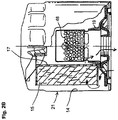
- FIG. 20 is a partial cross sectional view of an oil filter constructed in accordance with exemplary embodiments of the present invention.
- FIG. 21 is a cross sectional view of an additive cartridge or dispensing device in accordance with an alternative exemplary embodiment.
- a filter and method of making a filter is disclosed.
- the filter will be comprised of an additive cartridge for providing a means for introducing an additive into filtered oil.
- an additive cartridge and method of making is also disclosed wherein the cartridge provides a means for retaining an additive for dispersement into the oil over a period of time.
- relative positional terms like ‘upper’, ‘lower’, ‘top’, ‘bottom’, ‘horizontal’, ‘vertical’, and the like are used to refer to the filter and components in the orientation thereof shown in the drawings. These terms are used in an illustrative sense to describe the depicted embodiments, and are not meant to be limitative. It will be understood that in a specific application thereof, a filter may be installed on an engine in an orientation different from that shown in the drawings, such as inverted 180 degrees or transverse to that shown, and in such a case, the above-identified relative positional terms will no longer be accurate.
- FIGS. 1 and 2A there is shown an oil filter 20 according to a first exemplary embodiment of this invention.
- the direction of oil flow, through the filter 20 is shown by the arrows in FIG. 2A , which illustrate a flow path through the filter.
- the oil filter 20 generally includes a hollow cylindrical housing 22 which defines a hollow chamber 14 therein, a porous, mechanical filter element 15 within that chamber, and a centrally located additive cartridge 18 , also retained inside the housing chamber 14 .
- the housing 22 includes a hollow, generally cylindrical case 21 , and a base plate 24 sealingly attached to the case.
- a foraminous center tube 17 may, optionally, be provided within the filter housing 22 to supportively reinforce the mechanical filter element 15 thereon.
- An anti-drainback valve 19 is provided inside the filter housing 22 , at the base of the center tube 17 , to keep oil in the filter 20 during engine shutoff, when the filter is mounted in the orientation shown in FIG. 2 .
- the oil filter 20 may incorporate a spring-loaded pressure relief valve of a type known to those in the art.
- a retainer 45 may be provided above the center tube 17 , to exert a downward pressure thereon.
- the housing base plate 24 includes a plurality of inlet ports 28 formed therethrough and arranged in a circular pattern.
- the base plate 24 also includes a central outlet port 26 .
- the outlet port 26 has a plurality of female threads formed therein, to allow rotatable mounting of the filter 20 on an externally threaded hollow tubular fitting on an engine block (not shown).
- An annular external seal or gasket 33 ( FIG. 1 ) fits engagingly into a groove 30 formed at the bottom surface of the base plate, to resist oil leakage outwardly from the base of the filter.
- the mechanical filter element 15 includes a conventional cylindrical member made of accordion-pleated filter paper.
- the filter 20 contains an additive cartridge 18 disposed centrally and coaxially inside of the center tube 17 , in the middle of the mechanical filter element 15 .
- the additive cartridge 18 includes a hollow cartridge shell 35 , provided in a generally cylindrical shape, closed at the top and open at the bottom thereof in the orientation shown.
- the additive cartridge 18 also includes a solid additive composition 16 inside of the cartridge shell 35 .
- the hollow cartridge shell 35 has a cylindrical side wall 36 with a plurality of apertures 37 formed in a lower portion thereof.
- the cartridge shell 35 also includes a cap 38 , which covers the top of the side wall 36 and is integrally formed therewith.
- the cartridge shell 35 also includes a horizontal dividing wall 39 extending across a part of the side wall 36 above the apertures 37 .
- the dividing wall 39 subdivides the shell 35 into two sections, a lower baffle portion 40 and an upper dispenser housing 41 containing a hollow storage chamber 42 therein.
- the cartridge shell 35 has at least one opening 25 formed therethrough to allow fluid communication between the storage chamber 42 and the exterior of the cartridge.
- the opening(s) may be formed in the side wall 36 , the cap 38 , and/or the dividing wall 39 .
- the number and size of the opening(s) 25 may be selected to control the rate of dissolution of the additive material 16 from the dispenser housing 41 for a particular application.
- the additive cartridge 35 also has a horizontal flange 44 extending transversely outwardly from the side wall 36 at the base of the baffle 40 .
- the flange 44 may be included to cooperate with the anti-drainback valve 19 , to help seal against fluid bypassing the mechanical filter 15 under normal operation conditions.
- the additive cartridge 18 is preferred to be located in the flow path downstream of the mechanical filter element 15 , in order to allow the beneficial additive composition thereof to be released into the oil on the clean side of the filter element, after mechanical filtration has been achieved.
- the additive cartridge 18 contains a beneficial additive composition therein, which may be a solid block 16 , as shown in FIG. 2A .
- the additive composition 16 may be solid at standard temperature and pressure, defined as 25 degrees C. and one atmosphere pressure.
- the additive composition 16 may be injected into the cartridge shell 35 in a hot liquid state, and allowed to solidify as it cools.
- the additive composition 16 may be added in powdered form, or may be dispersed in a grease or wax.
- the additive composition 16 is preferred to be at least partially soluble in hot engine oil.
- the additive composition 16 includes one or more additives which may be selected from the group including basic conditioners, corrosion inhibitors, metal deactivators, antioxidants, dispersants, friction modifiers, oil stabilizers, pour point depressants, detergents, viscosity index improvers, anti-wear agents, extreme pressure additives, mixtures of the above additives, and/or other known beneficial additives.
- additives which may be selected from the group including basic conditioners, corrosion inhibitors, metal deactivators, antioxidants, dispersants, friction modifiers, oil stabilizers, pour point depressants, detergents, viscosity index improvers, anti-wear agents, extreme pressure additives, mixtures of the above additives, and/or other known beneficial additives.
- the basic conditioner of the additive cartridge is preferably a basic salt selected from the group consisting of calcium carbonate, potassium carbonate, potassium bicarbonate, aluminum dihydroxy sodium carbonate, magnesium oxide, magnesium carbonate, zinc oxide, sodium bicarbonate, sodium hydroxide, calcium hydroxide, potassium hydroxide, and mixtures thereof.
- the material selected for the cartridge shell 35 is preferred to be a material which remains stable in a hot oil environment.
- Preferred materials are metals such as steel and oil-tolerant plastics such as, e.g., polyacetals.
- the cartridge 18 allows the beneficial additive composition 16 to be slowly released into the oil, thereby conditioning the oil in a metered manner over time.
- the concentrated additive composition in the cartridge 18 may be provided as a plurality of separate individual pellets 48 , in order to provide greater surface area than is afforded with the solid additive block 16 of FIG. 2A .
- pellets 48 are used, they may be disassociated and separate from one another.
- the individual additive-dispensing pellets 48 housed within the cartridge shell 35 may be bonded together or otherwise cohesively associated with one another to form a substantially integral, yet highly porous structure capable of independent self-support. Where the pellets 48 are joined together in this way, the cartridge shell 35 is not required, and may be omitted if desired.
- the basic salt component of the additive 16 acts to counteract and neutralize acidic combustion products. This neutralization of acidic combustion products allows for a much longer useful life of some other oil additives such as, for example, dispersants and zinc dialkyldithiophosphate (ZDP), which are provided in the oil by the manufacturer thereof. This, in turn, allows for greater intervals between oil changes than is possible without the chemically active filter element.
- ZDP zinc dialkyldithiophosphate
- an additive cartridge 218 in accordance with a second embodiment of the invention is shown. Unless specified or depicted as being different herein, the additive cartridge 218 is substantially similar to the additive cartridge 18 as previously described. Those in the art will understand that the additive cartridge 218 of FIG. 6 may be substituted into the oil filter 20 of FIG. 2A instead of the additive cartridge 18 thereof, located above the center tube as indicated by FIG. 6 .
- the cartridge 218 in this embodiment includes a hollow cartridge shell 235 in the form of a basket.
- the shell 235 is either supported by or otherwise attached to the center tube 217 . While the center tube 217 is shown in simplified form in the drawings, it will be understood that it is a porous member.
- the shell 235 may include a top flange 219 for connecting to the center tube.
- the shell 235 has a recessed space formed in the top thereof for supportively receiving a retainer spring 245 .
- the shell 235 also has one or more openings 225 formed therein to allow fluid communication with between the interior thereof and the space surrounding the shell.
- a solid additive concentrate 216 is provided inside of the shell 235 , in a manner similar to that described above for the first embodiment.
- the additive may be in one piece or may be pelletized.
- an additive cartridge 318 in accordance with a third embodiment of the invention is shown. Unless specified or depicted as being different herein, the additive cartridge 318 is substantially similar to the additive cartridge 18 as previously described. Those in the art will understand that the additive cartridge 318 of FIG. 8 may be substituted into the oil filter 20 of FIG. 2A instead of the additive cartridge 18 and center tube 17 thereof.
- the cartridge 318 in this embodiment is a modified center tube.
- the cartridge 318 includes a hollow cylindrical shell 335 with a solid additive 316 contained therein.
- the shell 235 also has one or more openings 325 formed therein to allow fluid communication with between the interior thereof and the space surrounding the shell.
- a solid additive concentrate 316 is provided inside of the shell 235 , in a manner similar to that described above for the first embodiment.
- the additive may be in one piece or may be pelletized.
- disbursement device 418 comprises a shell portion 435 that defines a first receiving area 441 and a second receiving area 442 .
- first receiving area 441 and a second receiving area 442 are separated by a dividing wall 439 .
- first receiving area 441 defines a portion of an outlet fluid path of the oil filter wherein fluid flows into a plurality of openings 425 disposed above wall 439 , which provide fluid communication to first receiving area 441 .
- Disbursement device 418 comprises an annular flange 444 , which depends outwardly from the periphery of first receiving area 441 .
- Annular flange 444 provides a securement means for insertion of disbursement device 418 within a central portion of the oil filter.
- second receiving area 442 is defined by the side walls of shell portion 435 which depend downwardly from dividing wall 439 , and dividing wall 439 .
- Flow is permitted into second receiving area 442 by a plurality of openings 425 in shell portion 435 which are disposed below dividing wall 439 .
- access is also provided to second receiving area 442 through an opening 450 defined at the bottom of disbursement device 418 .
- Opening 450 is defined by the end of the walls of shell portion 435 which depend downwardly from dividing wall 439 .
- additive 416 when positioned in area 442 is in fluid communication with fluid flowing through the oil filter via openings 425 disposed below dividing wall 439 and opening 450 .
- Opening 425 and opening 450 maximize the surface area of additive 416 that is in fluid communication with the oil.
- this large amount of surface area exposure allows additive to more uniformly disperse into the oil.
- the rate of additive dispersement can be determined by the amount of exposed surface area.
- the rate of dispersement of the additive can be determined.
- shell portion 435 defines a cylinder that is open at either end and divided into two chambers by dividing wall 439 , which traverses across the diameter of the cylinder defined by shell portion 435 .
- additive 416 is disposed in additive containment chamber (area 442 ) wherein fluid communication to the additive is provided by a plurality of apertures in the wall portions of the cylinder defining the additive chamber as well as one of the open ends of the cylinder.
- disbursement device 418 is positioned such that annular flange 444 is disposed on a supporting surface and opening 450 is positioned to receive additive 416 .
- the larger opening 450 is positioned to receive the additive in a viscous or un-cured state.
- additive 416 is placed within receiving area in a liquid state and then cured into a gel form such that additive 416 remains in receiving area 442 once cartridge 418 is disposed into the oil filter. The consistency of the additive when cured will allow the same to be retained in area 442 while still allowing slow dispersement into oil or fluids passing through the filter.
- additive 416 may be dispersed into area 442 in a cured state. Additive 416 is retained within area 442 due to the frictional engagement of the additive against the surface of the dividing wall as well as the inner wall not having openings 25 disposed therein.
- the inner surfaces of walls 435 defining area 442 are textured to have a rough surface in order to increase the coefficient of friction between the surface of wall 435 and the additive disposed therein.
- One non-limiting example is to provide the wall of area 442 with a bead blasted surface.
- striations or grooves are disposed on the surface of wall 435 .
- materials comprising additive 416 are those disclosed in the following United States Patent Publications: U.S. 2004/0058830 A1; U.S. 2003/0134753 A1; U.S. 2003/0119682 A1; U.S. 2003/0087769 A1; U.S. 2003/0158051 A1; and U.S. 2002/0002118 A1; the contents of each of which are incorporated herein by reference thereto.
- the additive will stay in receiving area 442 when disbursement device is rotated such that opening 450 is disposed on the bottom of the disbursement device.
- a screen member 462 is disposed within second receiving area 442 .
- screen member 462 provides a means for retaining large portions of additive 416 therein while allowing smaller portions to be dispersed within the oil passing thereby.
- screen member 462 is capable of being positioned over opening 450 in addition to openings 425 .
- screen member is only disposed over opening 450 .
- the portion of wall 435 defining second receiving area 442 is replaced by a screen material 464 .
- the screen material is configured to surround and retain additive 416 therein while still allowing the same to be disbursed into the fluid passing through the filter and past the openings of the screen retaining the additive.
- the screen material 464 may be disposed over additive 416 or additive 416 may be dispersed into a screen member before it is secured to the remainder of disbursement device 418 .
- an outlet flow path is defined by a plurality of apertures disposed within the wall portion of the cylinder defining the flow chamber as well as the other open end 451 of the cylinder.
- the disbursement device is manufactured out of an easily molded material such as plastic wherein device 418 may be formed from an injection molding process and the materials comprising device 418 are capable of withstanding the temperatures and compositions encountered in the oil filter environment as well as the manufacturing processes for disposing the additive within the additive containment chamber, an example of such a material is an oil tolerable plastic such as; polyacetals, nylon 6/6 and equivalents thereof.
- an oil tolerable plastic such as; polyacetals, nylon 6/6 and equivalents thereof.
- Other contemplated materials include steel or other metals and/or alloys suitable for applications discussed herein.
- a first row of openings provide fluid communication into first receiving area 441
- a pair of rows of openings provide fluid communication into second receiving area 442 as well as opening 450 .
- the openings 425 providing fluid flow into first receiving area 441 are rectangular shape wherein the length of the opening is larger than the width while the openings 425 in the side walls defining second receiving area 442 are square or have a width substantially similar to a height.
- the size, configuration, location and number of apertures 425 may vary.
- FIGS. 9–18 illustrate a specific configuration of the additive cartridge or disbursement device 418 , it is understood that alternative configurations are considered to be within the scope of the present invention.
- shell portion 435 may define a non-circular (e.g., ellipse, square, rectangle, triangle, trapezoid etc.) housing for both the first and second receiving areas.
- the number, size, configuration and location of openings 425 may also vary to include non-rectangular or square openings as illustrated in the Figures.
- a plurality of spud stand off ribs 452 are located to protrude away from a surface of dividing wall 439 into first receiving area 441 .
- Stand off ribs provide a relief away from the surface of dividing wall 439 defining area 441 . This feature or protrusion will prevent an elongated spud from the engine being flushly mounted to the surface of dividing wall 439 thereby limiting fluid flow through the filter. Accordingly, ribs 452 ensure a limited amount of fluid flows through filter 420 .
- FIG. 19 an exploded view of an oil filter 420 constructed in accordance with an exemplary embodiment of the present invention is illustrated.
- additive cartridge or disbursement device 418 is inserted within a central opening of anti-drain back valve 419 , which in an exemplary embodiment comprises a rubber gasket having a flange portion that covers a plurality of inlet openings 428 in a baseplate 424 .
- the flange portion of the anti-drain back valve prevents reverse flow of un-filtered fluid through openings 428 while allowing flow of fluid into the filter through openings 428 .
- the elastomeric material of anti-drain back valve 419 allows the valve to operate in such a manner.
- filter 420 may be assembled manually or via an automated assembly line.
- filter element 415 comprises a pleated filter media that is configured to allow fluid flow therethrough and defines a cylinder or other equivalent structure through which oil must flow through prior to its entering the center portion of the filter element.
- filter element 415 comprises a pair of end caps 456 disposed at either end of filter element 415 .
- the end cap disposed proximate to additive cartridge 418 or at the inlet end of the filter comprises a plurality of flat surfaces 458 defined about the periphery of the end cap such that once the non-circular periphery of the end cap is disposed within the filter housing the filter element is centrally disposed within the housing while also providing a plurality of fluid paths between the flat surfaces of the end cap and the filter housing. Accordingly, when the filter media is disposed within the cylindrical housing 421 a plurality of fluid paths are defined for fluid flow in into the filter through openings 428 past anti-drain back valve 419 through the openings defined between housing 421 and flat surfaces 458 of end cap 456 and ultimately through the media of filter 415 .
- FIG. 20 a partial cross-sectional view of an oil filter 420 constructed in accordance with an exemplary embodiment of the present invention is illustrated. As illustrated flange 444 of cartridge or dispersement member 418 is sandwiched between a surface of base plate 424 and anti-drain back valve 419 .
- fluid flow through the filter is illustrated by arrows 458 .
- fluid to be filtered enters through openings 428 past anti-drain back valve 419 and through the openings defined between housing 421 and flat surfaces 458 of end cap 456 and ultimately through the media of filter 415 .
- the fluid passes through a plurality of openings 460 in a center tube 417 .
- Center tube 417 is disposed within filter housing 421 and comprises a plurality of openings therein to define a fluid path from the exterior of the center tube into the interior of the center tube.
- additive cartridge 418 is substantially disposed within center tube 417 and fluid therein is now in fluid communication with additive 416 disposed in second receiving area 442 via opening 450 and openings 425 disposed below dividing wall 439 .
- opening 450 is disposed in a facing space relationship away from the bottom of the filter, which in an exemplary embodiment comprises a retainer 445 to exert a force against one end of center tube 417 .
- Fluid flow is then permitted back into the engine via the outlet flow path defined by openings 425 disposed above dividing wall 439 and opening 451 , which ultimately allows fluid flow through a central outlet port 426 of baseplate 424 .
- Another feature of the present invention is that filtered oil in the filter during engine shut down is in constant contact with additive 416 thus, once the engine is started again fluid or oil with an additive disposed therein is carried to other parts of the engine. Accordingly, fluid containing additive 416 disposed therein is now used with the device (e.g., engine) having filter 420 disposed thereon.
- center tube 417 is manufactured to comprise a single integrally molded piece having additive cartridge 418 integrally molded therein.
- the openings in the sidewall of center tube 417 can be positioned to be proximate to the additive thus, increasing the flow past additive 416 .
- the number of openings in the walls of center tube 417 depend on the desired flow through filter 420 .
- additive 416 disposed in additive cartridge 418 provides a means for providing time release technology that may comprise any one of numerous additives, combinations thereof, including but not limited to detergents, antioxidants, ash-less antioxidants, dispersants and ash-less dispersants.
- Other contemplated compositions for additive 416 may include a fuel economy oil viscosity modifier wherein the additive or viscosity modifier causes and increase in engine fuel efficiency due to reduced friction in the engine.
- the additive may comprise a cold weather formula for use on colder months wherein it is more desirable to have a lower viscosity oil in order to assist in cold whether start ups.
- the filter is capable of being configured for seasonal use depending on geographical locations.
- an oil filter with additive 416 disposed therein will extend the acid neutralizing ability of the oil.
- oils can be more acidic within 3,000 miles, thus use of the additive of exemplary embodiments of the present invention will reduce sludge formation, reduce high temperature deposits and ring sticking and improves performance of engine oil.
Landscapes
- Chemical & Material Sciences (AREA)
- Chemical Kinetics & Catalysis (AREA)
- Engineering & Computer Science (AREA)
- Combustion & Propulsion (AREA)
- General Chemical & Material Sciences (AREA)
- Oil, Petroleum & Natural Gas (AREA)
- Organic Chemistry (AREA)
- Lubrication Details And Ventilation Of Internal Combustion Engines (AREA)
- Filtration Of Liquid (AREA)
Abstract
Description
Claims (37)
Priority Applications (13)
| Application Number | Priority Date | Filing Date | Title |
|---|---|---|---|
| US10/863,581 US7182863B2 (en) | 2000-05-08 | 2004-06-08 | Additive dispersing filter and method of making |
| CNB2005800189436A CN100536981C (en) | 2004-06-08 | 2005-06-07 | Additive dispersing filter and method of making |
| MXPA06013880A MXPA06013880A (en) | 2004-06-08 | 2005-06-07 | Additive dispersing filter and method of making. |
| AU2005254479A AU2005254479B2 (en) | 2004-06-08 | 2005-06-07 | Additive dispersing filter and method of making |
| EP05757664A EP1753519A1 (en) | 2004-06-08 | 2005-06-07 | Additive dispersing filter and method of making |
| PCT/US2005/019910 WO2005123218A1 (en) | 2004-06-08 | 2005-06-07 | Additive dispersing filter and method of making |
| BRPI0511798-4A BRPI0511798A (en) | 2004-06-08 | 2005-06-07 | filter, additive dispersion element configured to be accommodated in an oil filter, and additive dispersion element configured to be accommodated in an oil filter |
| JP2007527631A JP2008501525A (en) | 2004-06-08 | 2005-06-07 | Additive dispersion filter and manufacturing method |
| KR1020067025961A KR20070028408A (en) | 2004-06-08 | 2005-06-07 | Additive Distribution Filter and Manufacturing Method |
| CA2567652A CA2567652C (en) | 2004-06-08 | 2005-06-07 | Additive dispersing filter and method of making |
| ZA200700023A ZA200700023B (en) | 2004-06-08 | 2005-07-07 | Additive dispersing filter and method of making |
| US11/679,148 US7811462B2 (en) | 2000-05-08 | 2007-02-26 | Additive dispersing filter and method of making |
| US12/903,173 US8021558B2 (en) | 2000-05-08 | 2010-10-12 | Additive dispersing filter and method of making |
Applications Claiming Priority (4)
| Application Number | Priority Date | Filing Date | Title |
|---|---|---|---|
| US56603400A | 2000-05-08 | 2000-05-08 | |
| US09/867,973 US7291264B2 (en) | 2000-05-08 | 2001-05-30 | Staged oil filter incorporating additive-releasing particles |
| US10/352,344 US7018531B2 (en) | 2001-05-30 | 2003-01-27 | Additive dispensing cartridge for an oil filter, and oil filter incorporating same |
| US10/863,581 US7182863B2 (en) | 2000-05-08 | 2004-06-08 | Additive dispersing filter and method of making |
Related Parent Applications (1)
| Application Number | Title | Priority Date | Filing Date |
|---|---|---|---|
| US10/352,344 Continuation-In-Part US7018531B2 (en) | 2000-05-08 | 2003-01-27 | Additive dispensing cartridge for an oil filter, and oil filter incorporating same |
Related Child Applications (1)
| Application Number | Title | Priority Date | Filing Date |
|---|---|---|---|
| US11/679,148 Continuation US7811462B2 (en) | 2000-05-08 | 2007-02-26 | Additive dispersing filter and method of making |
Publications (2)
| Publication Number | Publication Date |
|---|---|
| US20050040092A1 US20050040092A1 (en) | 2005-02-24 |
| US7182863B2 true US7182863B2 (en) | 2007-02-27 |
Family
ID=34971932
Family Applications (3)
| Application Number | Title | Priority Date | Filing Date |
|---|---|---|---|
| US10/863,581 Expired - Lifetime US7182863B2 (en) | 2000-05-08 | 2004-06-08 | Additive dispersing filter and method of making |
| US11/679,148 Expired - Fee Related US7811462B2 (en) | 2000-05-08 | 2007-02-26 | Additive dispersing filter and method of making |
| US12/903,173 Expired - Lifetime US8021558B2 (en) | 2000-05-08 | 2010-10-12 | Additive dispersing filter and method of making |
Family Applications After (2)
| Application Number | Title | Priority Date | Filing Date |
|---|---|---|---|
| US11/679,148 Expired - Fee Related US7811462B2 (en) | 2000-05-08 | 2007-02-26 | Additive dispersing filter and method of making |
| US12/903,173 Expired - Lifetime US8021558B2 (en) | 2000-05-08 | 2010-10-12 | Additive dispersing filter and method of making |
Country Status (11)
| Country | Link |
|---|---|
| US (3) | US7182863B2 (en) |
| EP (1) | EP1753519A1 (en) |
| JP (1) | JP2008501525A (en) |
| KR (1) | KR20070028408A (en) |
| CN (1) | CN100536981C (en) |
| AU (1) | AU2005254479B2 (en) |
| BR (1) | BRPI0511798A (en) |
| CA (1) | CA2567652C (en) |
| MX (1) | MXPA06013880A (en) |
| WO (1) | WO2005123218A1 (en) |
| ZA (1) | ZA200700023B (en) |
Cited By (30)
| Publication number | Priority date | Publication date | Assignee | Title |
|---|---|---|---|---|
| US20050173325A1 (en) * | 2004-01-13 | 2005-08-11 | Mann & Hummel Gmbh | Additive dispensing filter apparatus |
| US20070235378A1 (en) * | 2004-03-05 | 2007-10-11 | Donaldson Corporation Company, Inc. | Top Load Liquid Filter Assembly for Use with Treatment Agent; and, Methods |
| US20080099407A1 (en) * | 2000-05-08 | 2008-05-01 | Derek Eilers | Additive dispersing filter and method of making |
| US20090064646A1 (en) * | 2004-08-06 | 2009-03-12 | Donaldson Company, Inc. | Air filter arrangement; assembly; and methods |
| US20090151311A1 (en) * | 2005-01-13 | 2009-06-18 | Donaldson Company, Inc. | Air filter cartridge and air cleaner assembly |
| US7625419B2 (en) | 2006-05-10 | 2009-12-01 | Donaldson Company, Inc. | Air filter arrangement; assembly; and, methods |
| US8034145B2 (en) | 2004-06-14 | 2011-10-11 | Donaldson Company, Inc. | Air filter arrangement; assembly; and, methods |
| WO2012017429A1 (en) * | 2010-08-02 | 2012-02-09 | Yair Tamir Meshulam | Compact filter valve and methods for fabrication, use and maintenance thereof |
| US20120080384A1 (en) * | 2010-09-30 | 2012-04-05 | Adan Reinosa | Method and apparatus for a parallel bypass filtration system for internal combustion engines and similar systems |
| US20120325752A1 (en) * | 2011-06-23 | 2012-12-27 | Fram Group IP, LLC | Additive dispensing filter and method |
| US8496723B2 (en) | 2005-01-13 | 2013-07-30 | Donaldson Company, Inc. | Air filter arrangement |
| US20140251883A1 (en) * | 2011-11-07 | 2014-09-11 | Toyota Jidosha Kabushiki Kaisha | OIL DETERIORATION PREVENTION DEVICE (as amended) |
| US9320997B2 (en) | 2013-06-28 | 2016-04-26 | Donaldson Company, Inc. | Air filter cartridges; air cleaner assemblies; housings; features; components; and, methods |
| US9555370B2 (en) | 2007-09-07 | 2017-01-31 | Donaldson Company, Inc. | Air filter assembly; components thereof; and, methods |
| US9623351B2 (en) | 2009-04-09 | 2017-04-18 | Cummins Filtration Ip, Inc. | Filtration sealing system |
| US9623350B2 (en) | 2013-03-01 | 2017-04-18 | Fram Group Ip Llc | Extended-life oil management system and method of using same |
| US9844743B2 (en) | 2011-11-07 | 2017-12-19 | Toyota Boshoku Kabushiki Kaisha | Oil deterioration prevention device |
| US10369498B2 (en) | 2012-05-07 | 2019-08-06 | Toyota Boshoku Kabushiki Kaisha | Oil deterioration suppressing apparatus |
| US10434454B2 (en) | 2011-06-30 | 2019-10-08 | Donaldson Company, Inc. | Filter cartridge |
| US11020698B2 (en) | 2015-12-11 | 2021-06-01 | Cummins Filtration Ip, Inc. | Filter with variable cross-section axial seal |
| US11110382B2 (en) | 2014-12-27 | 2021-09-07 | Donaldson Company, Inc. | Filter cartridges; air cleaner assemblies; housings; features; components; and, methods |
| US11141687B2 (en) | 2016-05-02 | 2021-10-12 | Cummins Filtration Ip, Inc. | Filter with interlocking housing interface |
| US11167234B2 (en) | 2016-03-18 | 2021-11-09 | Cummins Filtration Ip, Inc. | Interlocked stable filter assembly |
| US11198082B2 (en) | 2017-08-31 | 2021-12-14 | Donaldson Company, Inc. | Filter cartridges; air cleaner assemblies; housings; features; components; and methods |
| US11235275B2 (en) | 2017-03-16 | 2022-02-01 | Cummins Filtration Ip, Inc. | Filtration sealing system |
| US11298640B2 (en) | 2017-01-25 | 2022-04-12 | Cummins Filtration Ip, Inc. | Expandable threaded adaptor for threadless shell |
| US11724220B2 (en) | 2017-02-21 | 2023-08-15 | Cummins Filtration Ip, Inc. | Undulated interlocking housing-endplate interface geometry |
| US11772026B2 (en) | 2014-09-15 | 2023-10-03 | Donaldson Company, Inc. | Filter cartridges; air cleaner assemblies; housings; features; components; and, methods |
| US12263428B2 (en) | 2018-07-23 | 2025-04-01 | Cummins Filtration Sarl | Radial seal for spin-on filter |
| US12576348B2 (en) | 2020-02-11 | 2026-03-17 | Atmus Filtration Inc. | Advanced fuel filtration system with interlocking cartridge seal design |
Families Citing this family (28)
| Publication number | Priority date | Publication date | Assignee | Title |
|---|---|---|---|---|
| DE102004009907A1 (en) * | 2004-02-26 | 2005-09-29 | Mann + Hummel Gmbh | Liquid filter, in particular oil filter for an internal combustion engine |
| EP2865432B1 (en) | 2004-06-29 | 2020-09-09 | Donaldson Company, Inc. | Liquid filter arrangement |
| US8016125B2 (en) * | 2005-05-20 | 2011-09-13 | Lutek, Llc | Materials, filters, and systems for immobilizing combustion by-products and controlling lubricant viscosity |
| DE102005053653A1 (en) * | 2005-08-09 | 2007-02-15 | Daimlerchrysler Ag | oil module |
| US7473355B2 (en) | 2005-11-15 | 2009-01-06 | Purolator Filters Na Llc | Chemical additive carrier for filter |
| SG188908A1 (en) | 2006-07-14 | 2013-04-30 | Wisconsin Alumni Res Found | Adsorptive membranes for trapping viruses |
| US7481923B2 (en) * | 2006-08-28 | 2009-01-27 | Honeywell International Inc. | Additive dispersing filter and method of making |
| USD586880S1 (en) | 2006-11-17 | 2009-02-17 | Pur Water Purification Products Inc. | Faucet mount housing |
| USD592729S1 (en) | 2006-11-17 | 2009-05-19 | Pur Water Purification Products, Inc. | Dispenser cartridge |
| USD576250S1 (en) | 2006-11-17 | 2008-09-02 | Pur Water Purification Products, Inc. | Dispenser cartridge and pitcher |
| US9539531B2 (en) | 2007-02-13 | 2017-01-10 | Fram Group IP, LLC | Additive dispersing filter and method |
| JP2010518315A (en) * | 2007-02-13 | 2010-05-27 | ハネウェル・インターナショナル・インコーポレーテッド | Additive dispersion filter apparatus and method |
| US8926845B2 (en) * | 2008-02-13 | 2015-01-06 | Fram Group Ip Llc | Additive dispersing filter and method |
| WO2008112997A1 (en) * | 2007-03-15 | 2008-09-18 | Honeywell International Inc. | Lubricating oil conditioning filter containing improved pelletized conditioner |
| US20090101561A1 (en) * | 2007-10-19 | 2009-04-23 | The Lubrizol Corporation | Filter Cap Additive Delivery System |
| US20090194484A1 (en) * | 2008-02-01 | 2009-08-06 | Lutek, Llc | Oil Filters Containing Strong Base and Methods of Their Use |
| US7931817B2 (en) * | 2008-02-15 | 2011-04-26 | Honeywell International Inc. | Additive dispensing device and a thermally activated additive dispensing filter having the additive dispensing device |
| US9341309B1 (en) * | 2008-04-29 | 2016-05-17 | Wiliam A. Jacobs | Oil soluble additive injection apparatus |
| EP2310105A4 (en) * | 2008-07-21 | 2013-01-16 | 3M Innovative Properties Co | Apparatus for dispersing additive into a fluid stream |
| GB2467158B (en) * | 2009-01-26 | 2010-12-08 | Bao Yo Jei Co Ltd | Disposable oil filtering device |
| US20110048857A1 (en) * | 2009-09-01 | 2011-03-03 | Caterpillar Inc. | Lubrication system |
| US8426218B2 (en) * | 2010-10-19 | 2013-04-23 | Mclane Research Laboratories, Inc. | Fixation filter assembly |
| US10005014B2 (en) | 2012-01-30 | 2018-06-26 | Fram Group Ip Llc | Additive carrier for spin on filters |
| US20130248292A1 (en) * | 2012-03-22 | 2013-09-26 | GM Global Technology Operations LLC | Release and Retention of Viscosity Modifiers Based on Oil Temperature |
| US9089805B2 (en) * | 2013-06-25 | 2015-07-28 | Baldwin Filters, Inc. | Air filter and inlet tube assembly |
| FR3016803B1 (en) * | 2014-01-24 | 2016-02-12 | Pierre Marconi | MOBILE DEVICE FOR PRESSURIZED LIQUID FILTRATION EQUIPPED WITH A CONTAINMENT ENCLOSURE FOR A FILTER. |
| US20150219226A1 (en) * | 2014-02-04 | 2015-08-06 | Fram Group IP, LLC | Fluid flow controller and filter assembly with fluid flow controller |
| US10428703B2 (en) * | 2017-07-19 | 2019-10-01 | GM Global Technology Operations LLC | Machine lubricant additive distribution systems and methods |
Citations (77)
| Publication number | Priority date | Publication date | Assignee | Title |
|---|---|---|---|---|
| DE157197C (en) | ||||
| GB203354A (en) | 1922-03-04 | 1923-09-04 | Harry Mackenzie Ridge | Improvements in the purification of oils |
| US2262526A (en) | 1938-07-15 | 1941-11-11 | Sinclair Refining Co | Lubrication |
| FR51254E (en) | 1940-08-27 | 1942-02-18 | Continuous lubricating oil regeneration device for engines and other applications | |
| US2310305A (en) | 1937-12-31 | 1943-02-09 | Standard Oil Dev Co | Method and means for purifying lubricants |
| US2618586A (en) | 1950-11-03 | 1952-11-18 | Wigton Abbott Corp | Process for desulfurizing petroleum products in the liquid phase |
| GB904480A (en) | 1959-11-10 | 1962-08-29 | Degussa | A process for desulphurising liquid hydrocarbons |
| US3336223A (en) | 1965-06-08 | 1967-08-15 | Atlantic Refining Co | Method and means for maintaining an effective concentration of additives in oil |
| FR2330856A1 (en) | 1975-11-07 | 1977-06-03 | Monroe Auto Equipment Co | Motor oil filter contains an oil-soluble solid block - which replenishes the oil with additives |
| US4075098A (en) | 1975-04-01 | 1978-02-21 | Monroe Auto Equipment Company | Masking elements for dissolving oil improving body in an oil filter |
| US4113606A (en) | 1976-09-28 | 1978-09-12 | Chevron Research Company | Method of removing sulfur-containing impurities from hydrocarbons |
| US4144169A (en) | 1977-06-06 | 1979-03-13 | Monroe Auto Equipment Company | Filter unit |
| US4144166A (en) | 1977-03-24 | 1979-03-13 | Atlantic Richfield Company | Compositions, apparatus and methods useful for releasing solid lubricating oil additive |
| US4168225A (en) | 1976-02-11 | 1979-09-18 | Jackson Herman R | Method for removing sulfur impurities from petroleum liquids |
| SU572072A1 (en) | 1975-11-12 | 1980-04-25 | Институт нефтехимического синтеза им.А.В.Топчиева АН СССР | Method of purifying liquid and gas mixtures from mercaptans |
| US4211639A (en) | 1978-11-03 | 1980-07-08 | Jackson Herman R | Method for removing impurities and residual moisture from petroleum fuels |
| US4265748A (en) | 1980-01-11 | 1981-05-05 | Tecnocar S P A | Lubricant filter for internal combustion engines |
| US4523532A (en) | 1982-02-02 | 1985-06-18 | Rockwell International Corporation | Combustion method |
| US4557829A (en) | 1984-06-13 | 1985-12-10 | Champion Laboratories, Inc. | Two stage filter |
| US4660645A (en) | 1983-11-25 | 1987-04-28 | Exxon Research & Engineering Co. | Method for controlled introduction of reagent into a liquid |
| US4751901A (en) | 1987-10-13 | 1988-06-21 | Moor Stephen E | Composite oil filter |
| US4755289A (en) | 1986-06-27 | 1988-07-05 | Tecnocar S.P.A. | Lubricant filter for internal combustion engines |
| US4886599A (en) | 1986-10-23 | 1989-12-12 | Leybold Ag | Filter cartridge with series elements for chemical and mechanical filtration |
| US4888122A (en) | 1986-11-24 | 1989-12-19 | Mccready David F | Engine oil additive dry lubricant powder |
| US4895640A (en) | 1989-02-10 | 1990-01-23 | Jackson Herman R | Method for removing impurities and residual moisture from petroleum fuels |
| US4902408A (en) | 1987-08-13 | 1990-02-20 | Bayer Aktiengesellschaft | Process for removing hydrogen sulphide using metal compounds |
| US4906389A (en) | 1988-11-09 | 1990-03-06 | Exxon Research And Engineering Company | Method for reducing piston deposits |
| EP0416908A2 (en) | 1989-09-07 | 1991-03-13 | Exxon Research And Engineering Company | Filter system for rejuvenating lubricating oils |
| EP0416905A2 (en) | 1989-09-07 | 1991-03-13 | Exxon Research And Engineering Company | Method of removing sludge from lubricating oils |
| US5032259A (en) | 1988-12-24 | 1991-07-16 | He Qi Sheng | Friction-reducing lubricating-oil filter for internal combustion engine |
| US5057368A (en) | 1989-12-21 | 1991-10-15 | Allied-Signal | Filaments having trilobal or quadrilobal cross-sections |
| US5069970A (en) | 1989-01-23 | 1991-12-03 | Allied-Signal Inc. | Fibers and filters containing said fibers |
| US5094747A (en) | 1990-09-18 | 1992-03-10 | Allied-Signal Inc. | Removal of polynuclear aromatic compounds from motor vehicle fuel |
| US5199978A (en) | 1991-06-17 | 1993-04-06 | Exxon Research And Engineering Company | Process for removing elemental sulfur from fluids |
| US5209842A (en) | 1990-08-08 | 1993-05-11 | Moor Stephen E | Oil enhancing multifunction filter |
| US5225081A (en) | 1989-09-07 | 1993-07-06 | Exxon Research And Engineering Co. | Method for removing polynuclear aromatics from used lubricating oils |
| DE4200376A1 (en) | 1990-05-30 | 1993-07-15 | Tetsuo Aida | METHOD FOR DESULFURING HEATING OIL |
| WO1994011556A1 (en) | 1992-11-18 | 1994-05-26 | Hoechst Celanese Corporation | Fibrous structure containing immobilized particulate matter and process therefor |
| US5472875A (en) | 1991-05-01 | 1995-12-05 | Energy Biosystems Corporation | Continuous process for biocatalytic desulfurization of sulfur-bearing heterocyclic molecules |
| US5478463A (en) | 1989-09-07 | 1995-12-26 | Exxon Chemical Patents Inc. | Method of reducing sludge and varnish precursors in lubricating oils |
| US5527452A (en) | 1992-06-30 | 1996-06-18 | Metzhotraslevoe Nauchno-Proizvodstvennoe Obedinenie Ekologiya | Device for providing tribochemical mode of operation in a lubrication system for a mechanism |
| US5552040A (en) | 1992-09-24 | 1996-09-03 | Sundstrand Corporation | Method of increasing service life of oil and a filter for use therewith |
| US5591330A (en) | 1994-05-25 | 1997-01-07 | T/F Purifiner, Inc. | Oil filter containing an oil soluble thermoplastic additive material therein |
| US5704966A (en) | 1994-12-23 | 1998-01-06 | Alliedsignal Inc. | Method and apparatus for the continuous capturing and removal of gas molecules |
| US5713971A (en) | 1994-12-23 | 1998-02-03 | Alliedsignal Inc. | Filtration device using absorption for the removal of gas phase contaminants |
| US5718258A (en) | 1996-10-22 | 1998-02-17 | T/F Purifiner, Inc. | Releasing additives into engine oil |
| US5725031A (en) | 1996-08-01 | 1998-03-10 | Alliedsignal Inc. | Method for introducing PTFE into a spin-on oil filter |
| US5741433A (en) | 1996-06-21 | 1998-04-21 | Betzdearborn Inc. | Controlled release supplemental coolant additive |
| US5744236A (en) | 1996-11-27 | 1998-04-28 | Alliedsignal Inc. | Hollow fibers impregnated with solid particles |
| US5759394A (en) | 1996-11-27 | 1998-06-02 | Alliedsignal Inc. | Elongate fiber filter mechanically securing solid adsorbent particles between adjacent multilobes |
| US5891221A (en) | 1994-12-23 | 1999-04-06 | Alliedsignal Inc. | Chemical reagent package and method of operation effective at removing a wide range of odors |
| US5900153A (en) | 1994-08-22 | 1999-05-04 | Sanford; Sterling D. | Device with granular carbon filter medium for purification of gasoline used in the internal-combustion engine |
| US5902384A (en) | 1994-12-23 | 1999-05-11 | Alliedsignal Inc. | Wicking fiber with solid particulates for a high surface area odor removing filter and method of making |
| US5942323A (en) | 1995-01-27 | 1999-08-24 | Purafil, Inc. | Fiber filter and methods of use thereof |
| US5948248A (en) | 1997-07-18 | 1999-09-07 | Baldwin Filters, Inc. | Coolant filter having a delayed release supplemental coolant additive cartridge |
| US5951744A (en) | 1994-12-23 | 1999-09-14 | Alliedsignal Inc. | Multicomponent depth odor control filter and method of manufacture |
| US6117802A (en) | 1997-10-29 | 2000-09-12 | Alliedsignal Inc. | Electrically conductive shaped fibers |
| US6127036A (en) | 1997-10-27 | 2000-10-03 | Alliedsignal Inc. | Production of engineering fibers by formation of polymers within the channels of wicking fibers |
| US6126823A (en) | 1998-05-18 | 2000-10-03 | Donaldson Company, Inc. | Spin-on coolant filter |
| US6129835A (en) | 1998-12-28 | 2000-10-10 | International Fuel Cells, Llc | System and method for desulfurizing gasoline or diesel fuel to produce a low sulfur-content fuel for use in an internal combustion engine |
| EP1061251A2 (en) | 1999-06-16 | 2000-12-20 | Fleetguard, Inc. | Fuel filter including slow release additive |
| US6235519B1 (en) | 1998-02-26 | 2001-05-22 | Energy Biosystems Corporation | Gene involved in thiophene biotransformation from nocardia asteroides KGB1 |
| WO2001062871A1 (en) | 2000-02-24 | 2001-08-30 | International Fuel Cells, Llc | Method for desulfurizing gasoline or diesel fuel for use in an internal combustion engine |
| USRE37369E1 (en) | 1996-06-21 | 2001-09-18 | Fleetguard, Inc. | Slow release coolant filter |
| US20020002118A1 (en) | 2000-05-19 | 2002-01-03 | Brandt M. Karl | Lubrication additive |
| US6379564B1 (en) | 2000-05-08 | 2002-04-30 | Ronald Paul Rohrbach | Multi-stage fluid filter, and methods of making and using same |
| US20020136936A1 (en) | 2001-02-12 | 2002-09-26 | Grieve Malcolm James | Trapping method and system for energy conversion devices |
| WO2002096534A1 (en) | 2001-05-30 | 2002-12-05 | Honeywell International Inc. | Staged oil filter incorporating additive-releasing particles |
| US20030111398A1 (en) | 2001-05-30 | 2003-06-19 | Derek Eilers | Additive dispensing cartridge for an oil filter, and oil filter incorporating same |
| US20030119682A1 (en) | 1997-08-27 | 2003-06-26 | Ashland Inc. | Lubricant and additive formulation |
| US20030158051A1 (en) | 2001-09-21 | 2003-08-21 | Karol Thomas J. | Antioxidant additive compositions and lubricating compositions containing the same |
| US6639034B2 (en) | 1995-06-19 | 2003-10-28 | The Lubrizol Corporation | Dispersant-viscosity improvers for lubricating oil compositions |
| US20040058830A1 (en) | 2001-11-01 | 2004-03-25 | Kojiro Kan | Additive for lubricating oil and lubricating oil composition |
| US20040102335A1 (en) | 2002-11-25 | 2004-05-27 | The Lubrizol Corporation | Additive formulation for lubricating oils |
| US6743759B2 (en) | 2001-11-19 | 2004-06-01 | R.T. Vanderbilt Company, Inc. | Antioxidant, antiwear/extreme pressure additive compositions and lubricating compositions containing the same |
| US6774091B2 (en) | 1997-08-27 | 2004-08-10 | Ashland Inc. | Lubricant and additive formulation |
| US6843916B2 (en) | 2002-07-16 | 2005-01-18 | The Lubrizol Corporation | Slow release lubricant additives gel |
Family Cites Families (14)
| Publication number | Priority date | Publication date | Assignee | Title |
|---|---|---|---|---|
| DD157197A1 (en) | 1981-01-06 | 1982-10-20 | Andraschak Karl Heinz | METHOD FOR HYDRORAFFINATION OF DIESEL FUEL |
| CH642227B (en) | 1981-10-28 | Asulab Sa | WATCH WITH ANALOGUE DISPLAY DEVICE WHOSE DIAL IS SHAPED BY A LIQUID CRYSTAL DISPLAY CELL. | |
| US4557289A (en) | 1984-03-26 | 1985-12-10 | Kasnick Richard A | Hose nozzle for fire fighting kit |
| EP0591632B1 (en) | 1992-10-08 | 1998-04-22 | The B.F. Goodrich Company | Method of curing rubbers without forming nitrosamines |
| US5435346A (en) * | 1994-02-14 | 1995-07-25 | Alliedsignal Inc. | Device for treating and conditioning engine coolant |
| JPH09141011A (en) | 1995-11-16 | 1997-06-03 | Wako Sangyo Kk | Fluid filter and engine oil filtering device using the same |
| US5843284A (en) * | 1997-05-02 | 1998-12-01 | Paul J. T. Waters | Two-stage oil bypass filter device |
| US6860241B2 (en) * | 1999-06-16 | 2005-03-01 | Dober Chemical Corp. | Fuel filter including slow release additive |
| US6969461B2 (en) * | 2000-01-19 | 2005-11-29 | Baldwin Filters, Inc. | Combination particulate and acid-neutralizing filter |
| WO2001076485A1 (en) | 2000-04-05 | 2001-10-18 | Matsushita Electric Industrial Co. Ltd. | Biological information measuring instrument and biological information measuring method |
| US7182863B2 (en) * | 2000-05-08 | 2007-02-27 | Honeywell International, Inc. | Additive dispersing filter and method of making |
| CA2408880A1 (en) * | 2000-05-08 | 2001-11-15 | Ronald P. Rohrbach | Staged oil filter incorporating pelletized basic conditioner |
| US6827750B2 (en) * | 2001-08-24 | 2004-12-07 | Dober Chemical Corp | Controlled release additives in fuel systems |
| GB2394431B (en) * | 2001-08-24 | 2006-02-22 | Dober Chemical Corp | Controlled release of additives in fluid systems |
-
2004
- 2004-06-08 US US10/863,581 patent/US7182863B2/en not_active Expired - Lifetime
-
2005
- 2005-06-07 CN CNB2005800189436A patent/CN100536981C/en not_active Expired - Fee Related
- 2005-06-07 AU AU2005254479A patent/AU2005254479B2/en not_active Ceased
- 2005-06-07 KR KR1020067025961A patent/KR20070028408A/en not_active Abandoned
- 2005-06-07 JP JP2007527631A patent/JP2008501525A/en not_active Withdrawn
- 2005-06-07 BR BRPI0511798-4A patent/BRPI0511798A/en not_active Application Discontinuation
- 2005-06-07 EP EP05757664A patent/EP1753519A1/en not_active Withdrawn
- 2005-06-07 CA CA2567652A patent/CA2567652C/en not_active Expired - Fee Related
- 2005-06-07 MX MXPA06013880A patent/MXPA06013880A/en active IP Right Grant
- 2005-06-07 WO PCT/US2005/019910 patent/WO2005123218A1/en not_active Ceased
- 2005-07-07 ZA ZA200700023A patent/ZA200700023B/en unknown
-
2007
- 2007-02-26 US US11/679,148 patent/US7811462B2/en not_active Expired - Fee Related
-
2010
- 2010-10-12 US US12/903,173 patent/US8021558B2/en not_active Expired - Lifetime
Patent Citations (85)
| Publication number | Priority date | Publication date | Assignee | Title |
|---|---|---|---|---|
| DE157197C (en) | ||||
| GB203354A (en) | 1922-03-04 | 1923-09-04 | Harry Mackenzie Ridge | Improvements in the purification of oils |
| US2310305A (en) | 1937-12-31 | 1943-02-09 | Standard Oil Dev Co | Method and means for purifying lubricants |
| US2262526A (en) | 1938-07-15 | 1941-11-11 | Sinclair Refining Co | Lubrication |
| FR51254E (en) | 1940-08-27 | 1942-02-18 | Continuous lubricating oil regeneration device for engines and other applications | |
| US2618586A (en) | 1950-11-03 | 1952-11-18 | Wigton Abbott Corp | Process for desulfurizing petroleum products in the liquid phase |
| GB904480A (en) | 1959-11-10 | 1962-08-29 | Degussa | A process for desulphurising liquid hydrocarbons |
| US3336223A (en) | 1965-06-08 | 1967-08-15 | Atlantic Refining Co | Method and means for maintaining an effective concentration of additives in oil |
| US4075097A (en) | 1975-04-01 | 1978-02-21 | Monroe Auto Equipment Company | Oil filter with oil improving dissolving body |
| US4075098A (en) | 1975-04-01 | 1978-02-21 | Monroe Auto Equipment Company | Masking elements for dissolving oil improving body in an oil filter |
| FR2330856A1 (en) | 1975-11-07 | 1977-06-03 | Monroe Auto Equipment Co | Motor oil filter contains an oil-soluble solid block - which replenishes the oil with additives |
| SU572072A1 (en) | 1975-11-12 | 1980-04-25 | Институт нефтехимического синтеза им.А.В.Топчиева АН СССР | Method of purifying liquid and gas mixtures from mercaptans |
| US4168225A (en) | 1976-02-11 | 1979-09-18 | Jackson Herman R | Method for removing sulfur impurities from petroleum liquids |
| US4113606A (en) | 1976-09-28 | 1978-09-12 | Chevron Research Company | Method of removing sulfur-containing impurities from hydrocarbons |
| US4144166A (en) | 1977-03-24 | 1979-03-13 | Atlantic Richfield Company | Compositions, apparatus and methods useful for releasing solid lubricating oil additive |
| US4144169A (en) | 1977-06-06 | 1979-03-13 | Monroe Auto Equipment Company | Filter unit |
| US4211639A (en) | 1978-11-03 | 1980-07-08 | Jackson Herman R | Method for removing impurities and residual moisture from petroleum fuels |
| US4265748A (en) | 1980-01-11 | 1981-05-05 | Tecnocar S P A | Lubricant filter for internal combustion engines |
| US4523532A (en) | 1982-02-02 | 1985-06-18 | Rockwell International Corporation | Combustion method |
| US4660645A (en) | 1983-11-25 | 1987-04-28 | Exxon Research & Engineering Co. | Method for controlled introduction of reagent into a liquid |
| US4557829A (en) | 1984-06-13 | 1985-12-10 | Champion Laboratories, Inc. | Two stage filter |
| US4755289A (en) | 1986-06-27 | 1988-07-05 | Tecnocar S.P.A. | Lubricant filter for internal combustion engines |
| US4886599A (en) | 1986-10-23 | 1989-12-12 | Leybold Ag | Filter cartridge with series elements for chemical and mechanical filtration |
| US4888122A (en) | 1986-11-24 | 1989-12-19 | Mccready David F | Engine oil additive dry lubricant powder |
| US4902408A (en) | 1987-08-13 | 1990-02-20 | Bayer Aktiengesellschaft | Process for removing hydrogen sulphide using metal compounds |
| US4751901A (en) | 1987-10-13 | 1988-06-21 | Moor Stephen E | Composite oil filter |
| US4906389A (en) | 1988-11-09 | 1990-03-06 | Exxon Research And Engineering Company | Method for reducing piston deposits |
| US5032259A (en) | 1988-12-24 | 1991-07-16 | He Qi Sheng | Friction-reducing lubricating-oil filter for internal combustion engine |
| US5069970A (en) | 1989-01-23 | 1991-12-03 | Allied-Signal Inc. | Fibers and filters containing said fibers |
| US4895640A (en) | 1989-02-10 | 1990-01-23 | Jackson Herman R | Method for removing impurities and residual moisture from petroleum fuels |
| EP0416905A2 (en) | 1989-09-07 | 1991-03-13 | Exxon Research And Engineering Company | Method of removing sludge from lubricating oils |
| US5042617A (en) | 1989-09-07 | 1991-08-27 | Exxon Research & Engineering Company | Method of reducing the presence of sludge in lubricating oils |
| US5069799A (en) | 1989-09-07 | 1991-12-03 | Exxon Research & Engineering Company | Method for rejuvenating lubricating oils |
| EP0416908A2 (en) | 1989-09-07 | 1991-03-13 | Exxon Research And Engineering Company | Filter system for rejuvenating lubricating oils |
| US5478463A (en) | 1989-09-07 | 1995-12-26 | Exxon Chemical Patents Inc. | Method of reducing sludge and varnish precursors in lubricating oils |
| US5225081A (en) | 1989-09-07 | 1993-07-06 | Exxon Research And Engineering Co. | Method for removing polynuclear aromatics from used lubricating oils |
| US5057368A (en) | 1989-12-21 | 1991-10-15 | Allied-Signal | Filaments having trilobal or quadrilobal cross-sections |
| DE4200376A1 (en) | 1990-05-30 | 1993-07-15 | Tetsuo Aida | METHOD FOR DESULFURING HEATING OIL |
| US5209842A (en) | 1990-08-08 | 1993-05-11 | Moor Stephen E | Oil enhancing multifunction filter |
| US5094747A (en) | 1990-09-18 | 1992-03-10 | Allied-Signal Inc. | Removal of polynuclear aromatic compounds from motor vehicle fuel |
| US5472875A (en) | 1991-05-01 | 1995-12-05 | Energy Biosystems Corporation | Continuous process for biocatalytic desulfurization of sulfur-bearing heterocyclic molecules |
| US5199978A (en) | 1991-06-17 | 1993-04-06 | Exxon Research And Engineering Company | Process for removing elemental sulfur from fluids |
| US5527452A (en) | 1992-06-30 | 1996-06-18 | Metzhotraslevoe Nauchno-Proizvodstvennoe Obedinenie Ekologiya | Device for providing tribochemical mode of operation in a lubrication system for a mechanism |
| US5552040A (en) | 1992-09-24 | 1996-09-03 | Sundstrand Corporation | Method of increasing service life of oil and a filter for use therewith |
| WO1994011556A1 (en) | 1992-11-18 | 1994-05-26 | Hoechst Celanese Corporation | Fibrous structure containing immobilized particulate matter and process therefor |
| US5591330A (en) | 1994-05-25 | 1997-01-07 | T/F Purifiner, Inc. | Oil filter containing an oil soluble thermoplastic additive material therein |
| US5900153A (en) | 1994-08-22 | 1999-05-04 | Sanford; Sterling D. | Device with granular carbon filter medium for purification of gasoline used in the internal-combustion engine |
| US5891221A (en) | 1994-12-23 | 1999-04-06 | Alliedsignal Inc. | Chemical reagent package and method of operation effective at removing a wide range of odors |
| US5951744A (en) | 1994-12-23 | 1999-09-14 | Alliedsignal Inc. | Multicomponent depth odor control filter and method of manufacture |
| US5704966A (en) | 1994-12-23 | 1998-01-06 | Alliedsignal Inc. | Method and apparatus for the continuous capturing and removal of gas molecules |
| US6004381A (en) | 1994-12-23 | 1999-12-21 | Alliedsignal Inc. | Filtration device and method using absorption for the removal of gas phase contaminants |
| US5713971A (en) | 1994-12-23 | 1998-02-03 | Alliedsignal Inc. | Filtration device using absorption for the removal of gas phase contaminants |
| US5902384A (en) | 1994-12-23 | 1999-05-11 | Alliedsignal Inc. | Wicking fiber with solid particulates for a high surface area odor removing filter and method of making |
| US5942323A (en) | 1995-01-27 | 1999-08-24 | Purafil, Inc. | Fiber filter and methods of use thereof |
| US6639034B2 (en) | 1995-06-19 | 2003-10-28 | The Lubrizol Corporation | Dispersant-viscosity improvers for lubricating oil compositions |
| US5741433A (en) | 1996-06-21 | 1998-04-21 | Betzdearborn Inc. | Controlled release supplemental coolant additive |
| USRE37369E1 (en) | 1996-06-21 | 2001-09-18 | Fleetguard, Inc. | Slow release coolant filter |
| US6045692A (en) | 1996-08-01 | 2000-04-04 | Alliedsignal Inc. | Oil filter to introduce anti-wear additives into engine lubricating system |
| US5725031A (en) | 1996-08-01 | 1998-03-10 | Alliedsignal Inc. | Method for introducing PTFE into a spin-on oil filter |
| US5718258A (en) | 1996-10-22 | 1998-02-17 | T/F Purifiner, Inc. | Releasing additives into engine oil |
| US5759394A (en) | 1996-11-27 | 1998-06-02 | Alliedsignal Inc. | Elongate fiber filter mechanically securing solid adsorbent particles between adjacent multilobes |
| US6048614A (en) | 1996-11-27 | 2000-04-11 | Alliedsignal Inc. | Electrically charged filtration media |
| US5744236A (en) | 1996-11-27 | 1998-04-28 | Alliedsignal Inc. | Hollow fibers impregnated with solid particles |
| US5948248A (en) | 1997-07-18 | 1999-09-07 | Baldwin Filters, Inc. | Coolant filter having a delayed release supplemental coolant additive cartridge |
| US6774091B2 (en) | 1997-08-27 | 2004-08-10 | Ashland Inc. | Lubricant and additive formulation |
| US20030119682A1 (en) | 1997-08-27 | 2003-06-26 | Ashland Inc. | Lubricant and additive formulation |
| US6127036A (en) | 1997-10-27 | 2000-10-03 | Alliedsignal Inc. | Production of engineering fibers by formation of polymers within the channels of wicking fibers |
| US6117802A (en) | 1997-10-29 | 2000-09-12 | Alliedsignal Inc. | Electrically conductive shaped fibers |
| US6235519B1 (en) | 1998-02-26 | 2001-05-22 | Energy Biosystems Corporation | Gene involved in thiophene biotransformation from nocardia asteroides KGB1 |
| US6126823A (en) | 1998-05-18 | 2000-10-03 | Donaldson Company, Inc. | Spin-on coolant filter |
| US6129835A (en) | 1998-12-28 | 2000-10-10 | International Fuel Cells, Llc | System and method for desulfurizing gasoline or diesel fuel to produce a low sulfur-content fuel for use in an internal combustion engine |
| EP1061251A2 (en) | 1999-06-16 | 2000-12-20 | Fleetguard, Inc. | Fuel filter including slow release additive |
| US6238554B1 (en) | 1999-06-16 | 2001-05-29 | Fleetguard, Inc. | Fuel filter including slow release additive |
| EP1061251A3 (en) | 1999-06-16 | 2001-06-20 | Fleetguard, Inc. | Fuel filter including slow release additive |
| WO2001062871A1 (en) | 2000-02-24 | 2001-08-30 | International Fuel Cells, Llc | Method for desulfurizing gasoline or diesel fuel for use in an internal combustion engine |
| US6379564B1 (en) | 2000-05-08 | 2002-04-30 | Ronald Paul Rohrbach | Multi-stage fluid filter, and methods of making and using same |
| US20020002118A1 (en) | 2000-05-19 | 2002-01-03 | Brandt M. Karl | Lubrication additive |
| US20020136936A1 (en) | 2001-02-12 | 2002-09-26 | Grieve Malcolm James | Trapping method and system for energy conversion devices |
| WO2002096534A1 (en) | 2001-05-30 | 2002-12-05 | Honeywell International Inc. | Staged oil filter incorporating additive-releasing particles |
| US20030111398A1 (en) | 2001-05-30 | 2003-06-19 | Derek Eilers | Additive dispensing cartridge for an oil filter, and oil filter incorporating same |
| US20030158051A1 (en) | 2001-09-21 | 2003-08-21 | Karol Thomas J. | Antioxidant additive compositions and lubricating compositions containing the same |
| US20040058830A1 (en) | 2001-11-01 | 2004-03-25 | Kojiro Kan | Additive for lubricating oil and lubricating oil composition |
| US6743759B2 (en) | 2001-11-19 | 2004-06-01 | R.T. Vanderbilt Company, Inc. | Antioxidant, antiwear/extreme pressure additive compositions and lubricating compositions containing the same |
| US6843916B2 (en) | 2002-07-16 | 2005-01-18 | The Lubrizol Corporation | Slow release lubricant additives gel |
| US20040102335A1 (en) | 2002-11-25 | 2004-05-27 | The Lubrizol Corporation | Additive formulation for lubricating oils |
Non-Patent Citations (2)
| Title |
|---|
| International Search Report Dated Jun. 3, 2004, International Application No. PCT/US2004/002144. |
| Written Opinion of International Searching Authority Dated Jun. 3, 2004, International Application No. PCT/US2004/002144. |
Cited By (84)
| Publication number | Priority date | Publication date | Assignee | Title |
|---|---|---|---|---|
| US7811462B2 (en) * | 2000-05-08 | 2010-10-12 | Honeywell International, Inc. | Additive dispersing filter and method of making |
| US20080099407A1 (en) * | 2000-05-08 | 2008-05-01 | Derek Eilers | Additive dispersing filter and method of making |
| US8021558B2 (en) * | 2000-05-08 | 2011-09-20 | Fram Group Ip Llc | Additive dispersing filter and method of making |
| US20110084032A1 (en) * | 2000-05-08 | 2011-04-14 | Derek Eilers | Additive dispersing filter and method of making |
| US7323102B2 (en) * | 2004-01-13 | 2008-01-29 | Mann & Hummel Gmbh | Additive dispensing filter apparatus |
| US20050173325A1 (en) * | 2004-01-13 | 2005-08-11 | Mann & Hummel Gmbh | Additive dispensing filter apparatus |
| US20070235378A1 (en) * | 2004-03-05 | 2007-10-11 | Donaldson Corporation Company, Inc. | Top Load Liquid Filter Assembly for Use with Treatment Agent; and, Methods |
| US9120047B2 (en) | 2004-06-14 | 2015-09-01 | Donaldson Company, Inc. | Air filter arrangement; assembly; and, methods |
| US8034145B2 (en) | 2004-06-14 | 2011-10-11 | Donaldson Company, Inc. | Air filter arrangement; assembly; and, methods |
| US9937455B2 (en) | 2004-06-14 | 2018-04-10 | Donaldson Company, Inc. | Air filter arrangement; assembly; and, methods |
| US10603618B2 (en) | 2004-06-14 | 2020-03-31 | Donaldson Company, Inc. | Air filter arrangement; assembly; and, methods |
| US8480779B2 (en) * | 2004-06-14 | 2013-07-09 | Donaldson Company, Inc. | Air filter arrangement; assembly; and, methods |
| US11291943B2 (en) | 2004-06-14 | 2022-04-05 | Donaldson Company, Inc. | Air filter arrangement; assembly; and, methods |
| US11759744B2 (en) | 2004-08-06 | 2023-09-19 | Donaldson Company, Inc. | Air filter arrangement; assembly; and, methods |
| US20090064646A1 (en) * | 2004-08-06 | 2009-03-12 | Donaldson Company, Inc. | Air filter arrangement; assembly; and methods |
| US9795911B2 (en) | 2004-08-06 | 2017-10-24 | Donaldson Company, Inc. | Air filter arrangement; assembly; and, methods |
| US11207632B2 (en) | 2004-08-06 | 2021-12-28 | Donaldson Company, Inc. | Air filter arrangement; assembly; and, methods |
| US8277532B2 (en) | 2004-08-06 | 2012-10-02 | Donaldson Company, Inc. | Air filter arrangement; assembly; and methods |
| US8906128B2 (en) | 2004-08-06 | 2014-12-09 | Donaldson Company, Inc. | Air filter arrangement; assembly; and, methods |
| US10556201B2 (en) | 2004-08-06 | 2020-02-11 | Donaldson Company, Inc. | Air filter arrangement; assembly; and, methods |
| US11951429B2 (en) | 2005-01-13 | 2024-04-09 | Donaldson Company, Inc. | Air filter arrangement; assembly; and, methods |
| US10421034B2 (en) | 2005-01-13 | 2019-09-24 | Donaldson Company, Inc. | Air filter arrangement; assembly; and, methods |
| US12138574B2 (en) | 2005-01-13 | 2024-11-12 | Donaldson Company, Inc. | Air Filter Arrangement; Assembly; and, Methods |
| US8636820B2 (en) | 2005-01-13 | 2014-01-28 | Donaldson Company, Inc. | Air filter arrangement |
| US8496723B2 (en) | 2005-01-13 | 2013-07-30 | Donaldson Company, Inc. | Air filter arrangement |
| US10864475B2 (en) | 2005-01-13 | 2020-12-15 | Donaldson Company, Inc. | Air filter arrangement; assembly; and, methods |
| US20090151311A1 (en) * | 2005-01-13 | 2009-06-18 | Donaldson Company, Inc. | Air filter cartridge and air cleaner assembly |
| US8292983B2 (en) | 2005-01-13 | 2012-10-23 | Donaldson Company, Inc. | Air filter cartridge and air cleaner assembly |
| US9180399B2 (en) | 2005-01-13 | 2015-11-10 | Donaldson Company, Inc. | Air filter arrangement |
| US12070711B2 (en) | 2005-01-13 | 2024-08-27 | Donaldson Company, Inc. | Air filter arrangement; assembly; and, methods |
| US9527023B2 (en) | 2005-01-13 | 2016-12-27 | Donaldson Comapny, Inc. | Air filter arrangement; assembly; and, methods |
| US10315144B2 (en) | 2005-01-13 | 2019-06-11 | Donaldson Company, Inc. | Air filter arrangement; assembly; and, methods |
| US10065145B2 (en) | 2005-01-13 | 2018-09-04 | Donaldson Company, Inc. | Air filter arrangement; assembly; and, methods |
| US8709119B2 (en) | 2005-01-13 | 2014-04-29 | Donaldson Company, Inc. | Air filter cartridge and air cleaner assembly |
| US11826689B2 (en) | 2005-01-13 | 2023-11-28 | Donaldson Company, Inc. | Air filter arrangement; assembly; and, methods |
| US11020699B2 (en) | 2005-01-13 | 2021-06-01 | Donaldson Company, Inc. | Air filter arrangement; assembly; and, methods |
| US8062399B2 (en) | 2006-05-10 | 2011-11-22 | Donaldson Company, Inc. | Air filter arrangement; assembly; and, methods |
| US7625419B2 (en) | 2006-05-10 | 2009-12-01 | Donaldson Company, Inc. | Air filter arrangement; assembly; and, methods |
| US8328897B2 (en) | 2006-05-10 | 2012-12-11 | Donaldson Company, Inc. | Air cleaner arrangement; assembly; and, methods |
| US9555370B2 (en) | 2007-09-07 | 2017-01-31 | Donaldson Company, Inc. | Air filter assembly; components thereof; and, methods |
| US10422306B2 (en) | 2007-09-07 | 2019-09-24 | Donaldson Company, Inc. | Air filter assembly; components thereof; and, methods |
| US11833459B2 (en) | 2009-04-09 | 2023-12-05 | Cummins Filtration Ip, Inc. | Filtration sealing system |
| US9782708B2 (en) | 2009-04-09 | 2017-10-10 | Cummins Filtration Ip, Inc. | Filtration sealing system |
| US9623351B2 (en) | 2009-04-09 | 2017-04-18 | Cummins Filtration Ip, Inc. | Filtration sealing system |
| US10112138B2 (en) | 2009-04-09 | 2018-10-30 | Cummins Filtration Ip, Inc. | Filtration sealing system |
| WO2012017429A1 (en) * | 2010-08-02 | 2012-02-09 | Yair Tamir Meshulam | Compact filter valve and methods for fabrication, use and maintenance thereof |
| US9109478B2 (en) * | 2010-09-30 | 2015-08-18 | Pareto Point Industries, Inc. | Method and apparatus for a parallel bypass filtration system for internal combustion engines and similar systems |
| US20150151225A1 (en) * | 2010-09-30 | 2015-06-04 | Pareto Point Industries, Inc. | Method and apparatus for a parallel bypass filtration system for internal combustion engines and similar systems |
| US8945400B2 (en) * | 2010-09-30 | 2015-02-03 | Pareto Point Industries, Inc. | Method and apparatus for a parallel bypass filtration system for internal combustion engines and similar systems |
| US20120080384A1 (en) * | 2010-09-30 | 2012-04-05 | Adan Reinosa | Method and apparatus for a parallel bypass filtration system for internal combustion engines and similar systems |
| US20120325752A1 (en) * | 2011-06-23 | 2012-12-27 | Fram Group IP, LLC | Additive dispensing filter and method |
| US10434454B2 (en) | 2011-06-30 | 2019-10-08 | Donaldson Company, Inc. | Filter cartridge |
| US10145275B2 (en) * | 2011-11-07 | 2018-12-04 | Toyota Boshoku Kabushiki Kaisha | Oil deterioration prevention device |
| US20140251883A1 (en) * | 2011-11-07 | 2014-09-11 | Toyota Jidosha Kabushiki Kaisha | OIL DETERIORATION PREVENTION DEVICE (as amended) |
| US9844743B2 (en) | 2011-11-07 | 2017-12-19 | Toyota Boshoku Kabushiki Kaisha | Oil deterioration prevention device |
| US10369498B2 (en) | 2012-05-07 | 2019-08-06 | Toyota Boshoku Kabushiki Kaisha | Oil deterioration suppressing apparatus |
| US9623350B2 (en) | 2013-03-01 | 2017-04-18 | Fram Group Ip Llc | Extended-life oil management system and method of using same |
| US12115484B2 (en) | 2013-06-28 | 2024-10-15 | Donaldson Company, Inc. | Filter cartridges; air cleaner assemblies; housings; features; components; and, methods |
| US11752460B2 (en) | 2013-06-28 | 2023-09-12 | Donaldson Company, Inc. | Filter cartridges; air cleaner assemblies; housings; features; components; and, methods |
| US10610816B2 (en) | 2013-06-28 | 2020-04-07 | Donaldson Company, Inc. | Filter cartridges; air cleaner assemblies; housings; features; components; and, methods |
| US11298643B2 (en) | 2013-06-28 | 2022-04-12 | Donaldson Company, Inc. | Filter cartridges; air cleaner assemblies; housings; features; components; and, methods |
| US12186694B2 (en) | 2013-06-28 | 2025-01-07 | Donaldson Company, Inc. | Filter cartridges; air cleaner assemblies; housings; features; components; and, methods |
| US9320997B2 (en) | 2013-06-28 | 2016-04-26 | Donaldson Company, Inc. | Air filter cartridges; air cleaner assemblies; housings; features; components; and, methods |
| US10046260B2 (en) | 2013-06-28 | 2018-08-14 | Donaldson Company, Inc. | Air filter cartridges; air cleaner assemblies; housings; features; components; and, methods |
| US12145093B2 (en) | 2014-09-15 | 2024-11-19 | Donaldson Company, Inc. | Filter cartridges; air cleaner assemblies; housings; features; components; and, methods |
| US11772026B2 (en) | 2014-09-15 | 2023-10-03 | Donaldson Company, Inc. | Filter cartridges; air cleaner assemblies; housings; features; components; and, methods |
| US12168194B2 (en) | 2014-12-27 | 2024-12-17 | Donaldson Company, Inc. | Filter cartridges; air cleaner assemblies; housings; features; components; and, methods |
| US11110382B2 (en) | 2014-12-27 | 2021-09-07 | Donaldson Company, Inc. | Filter cartridges; air cleaner assemblies; housings; features; components; and, methods |
| US11020698B2 (en) | 2015-12-11 | 2021-06-01 | Cummins Filtration Ip, Inc. | Filter with variable cross-section axial seal |
| US12551830B2 (en) | 2016-03-18 | 2026-02-17 | Atmus Filtration IP Inc. | Interlocked stable filter assembly |
| US11813559B2 (en) | 2016-03-18 | 2023-11-14 | Cummins Filtration Ip, Inc. | Interlocked stable filter assembly |
| US11167234B2 (en) | 2016-03-18 | 2021-11-09 | Cummins Filtration Ip, Inc. | Interlocked stable filter assembly |
| US11660560B2 (en) | 2016-05-02 | 2023-05-30 | Cummins Filtration Ip, Inc. | Filter with interlocking housing interface |
| US11141687B2 (en) | 2016-05-02 | 2021-10-12 | Cummins Filtration Ip, Inc. | Filter with interlocking housing interface |
| US11298640B2 (en) | 2017-01-25 | 2022-04-12 | Cummins Filtration Ip, Inc. | Expandable threaded adaptor for threadless shell |
| US11724220B2 (en) | 2017-02-21 | 2023-08-15 | Cummins Filtration Ip, Inc. | Undulated interlocking housing-endplate interface geometry |
| US12330099B2 (en) | 2017-02-21 | 2025-06-17 | Cummins Filtration Ip, Inc. | Undulated interlocking housing-endplate interface geometry |
| US11235275B2 (en) | 2017-03-16 | 2022-02-01 | Cummins Filtration Ip, Inc. | Filtration sealing system |
| US12036499B2 (en) | 2017-08-31 | 2024-07-16 | Donaldson Company, Inc | Filter cartridges; air cleaner assemblies; housings; features; components; and, methods |
| US11198082B2 (en) | 2017-08-31 | 2021-12-14 | Donaldson Company, Inc. | Filter cartridges; air cleaner assemblies; housings; features; components; and methods |
| US12357934B2 (en) | 2017-08-31 | 2025-07-15 | Donaldson Company, Inc. | Filter cartridges; air cleaner assemblies; housings; features; components; and, methods |
| US11801466B2 (en) | 2017-08-31 | 2023-10-31 | Donaldson Company, Inc. | Filter cartridges; air cleaner assemblies; housings; features; components; and, methods |
| US12263428B2 (en) | 2018-07-23 | 2025-04-01 | Cummins Filtration Sarl | Radial seal for spin-on filter |
| US12576348B2 (en) | 2020-02-11 | 2026-03-17 | Atmus Filtration Inc. | Advanced fuel filtration system with interlocking cartridge seal design |
Also Published As
| Publication number | Publication date |
|---|---|
| CN100536981C (en) | 2009-09-09 |
| AU2005254479B2 (en) | 2010-09-09 |
| CA2567652C (en) | 2013-02-19 |
| US7811462B2 (en) | 2010-10-12 |
| WO2005123218A1 (en) | 2005-12-29 |
| CN1964771A (en) | 2007-05-16 |
| US20050040092A1 (en) | 2005-02-24 |
| EP1753519A1 (en) | 2007-02-21 |
| JP2008501525A (en) | 2008-01-24 |
| AU2005254479A1 (en) | 2005-12-29 |
| US20080099407A1 (en) | 2008-05-01 |
| MXPA06013880A (en) | 2007-03-07 |
| BRPI0511798A (en) | 2008-01-15 |
| ZA200700023B (en) | 2008-09-25 |
| US8021558B2 (en) | 2011-09-20 |
| US20110084032A1 (en) | 2011-04-14 |
| CA2567652A1 (en) | 2005-12-29 |
| KR20070028408A (en) | 2007-03-12 |
Similar Documents
| Publication | Publication Date | Title |
|---|---|---|
| US7182863B2 (en) | Additive dispersing filter and method of making | |
| US7018531B2 (en) | Additive dispensing cartridge for an oil filter, and oil filter incorporating same | |
| US6623636B2 (en) | Staged oil filter incorporating timed release oil conditioner | |
| US7588691B2 (en) | Additive dispersing filter and method of making | |
| WO2008101006A9 (en) | Additive dispersing filter and method | |
| US9539531B2 (en) | Additive dispersing filter and method |
Legal Events
| Date | Code | Title | Description |
|---|---|---|---|
| AS | Assignment |
Owner name: HONEYWELL INTERNATIONAL, INC., NEW JERSEY Free format text: ASSIGNMENT OF ASSIGNORS INTEREST;ASSIGNORS:EILERS, DEREK;BILSKI, GERARD W.;AUXTER, DANIEL J.;AND OTHERS;REEL/FRAME:015955/0187;SIGNING DATES FROM 20041025 TO 20041027 |
|
| STCF | Information on status: patent grant |
Free format text: PATENTED CASE |
|
| FPAY | Fee payment |
Year of fee payment: 4 |
|
| AS | Assignment |
Owner name: FRAM GROUP IP LLC, NEW ZEALAND Free format text: ASSIGNMENT OF ASSIGNORS INTEREST;ASSIGNOR:HONEYWELL INTERNATIONAL INC.;REEL/FRAME:026671/0907 Effective date: 20110729 |
|
| AS | Assignment |
Owner name: CREDIT SUISSE AG, AS FIRST LIEN COLLATERAL AGENT, Free format text: SECURITY AGREEMENT;ASSIGNORS:FRAM GROUP IP LLC;PRESTONE PRODUCTS CORPORATION;REEL/FRAME:026732/0670 Effective date: 20110729 Owner name: CREDIT SUISSE AG, AS FIRST LIEN COLLATERAL AGENT, NEW YORK Free format text: SECURITY AGREEMENT;ASSIGNORS:FRAM GROUP IP LLC;PRESTONE PRODUCTS CORPORATION;REEL/FRAME:026732/0670 Effective date: 20110729 |
|
| AS | Assignment |
Owner name: CREDIT SUISSE AG, AS SECOND LIEN COLLATERAL AGENT, Free format text: SECURITY AGREEMENT;ASSIGNORS:FRAM GROUP IP LLC;PRESTONE PRODUCTS CORPORATION;REEL/FRAME:026740/0089 Effective date: 20110729 Owner name: CREDIT SUISSE AG, AS SECOND LIEN COLLATERAL AGENT, NEW YORK Free format text: SECURITY AGREEMENT;ASSIGNORS:FRAM GROUP IP LLC;PRESTONE PRODUCTS CORPORATION;REEL/FRAME:026740/0089 Effective date: 20110729 |
|
| FPAY | Fee payment |
Year of fee payment: 8 |
|
| AS | Assignment |
Owner name: CREDIT SUISSE AG, CAYMAN ISLANDS BRANCH, AS COLLATERAL AGENT, NEW YORK Free format text: SECURITY INTEREST;ASSIGNOR:FRAM GROUP IP LLC;REEL/FRAME:041190/0001 Effective date: 20161223 Owner name: CREDIT SUISSE AG, CAYMAN ISLANDS BRANCH, AS COLLATERAL AGENT, NEW YORK Free format text: SECURITY INTEREST;ASSIGNOR:FRAM GROUP IP LLC;REEL/FRAME:041190/0278 Effective date: 20161223 Owner name: FRAM GROUP IP LLC, ILLINOIS Free format text: RELEASE BY SECURED PARTY;ASSIGNOR:CREDIT SUISSE AG, CAYMAN ISLANDS BRANCH, AS COLLATERAL AGENT;REEL/FRAME:041189/0938 Effective date: 20161223 Owner name: CREDIT SUISSE AG, CAYMAN ISLANDS BRANCH, AS COLLAT Free format text: SECURITY INTEREST;ASSIGNOR:FRAM GROUP IP LLC;REEL/FRAME:041190/0001 Effective date: 20161223 Owner name: FRAM GROUP IP LLC, ILLINOIS Free format text: RELEASE BY SECURED PARTY;ASSIGNOR:CREDIT SUISSE AG, CAYMAN ISLANDS BRANCH, AS COLLATERAL AGENT;REEL/FRAME:041189/0782 Effective date: 20161223 Owner name: CREDIT SUISSE AG, CAYMAN ISLANDS BRANCH, AS COLLAT Free format text: SECURITY INTEREST;ASSIGNOR:FRAM GROUP IP LLC;REEL/FRAME:041190/0278 Effective date: 20161223 |
|
| AS | Assignment |
Owner name: BMO HARRIS BANK, N.A., AS SUCCESSOR COLLATERAL AGENT, ILLINOIS Free format text: ASSIGNMENT OF ASSIGNORS INTEREST;ASSIGNOR:CREDIT SUISSE AG, CAYMAN ISLANDS BRANCH, AS RESIGNING COLLATERAL AGENT;REEL/FRAME:041739/0040 Effective date: 20170216 Owner name: BMO HARRIS BANK, N.A., AS SUCCESSOR COLLATERAL AGE Free format text: ASSIGNMENT OF ASSIGNORS INTEREST;ASSIGNOR:CREDIT SUISSE AG, CAYMAN ISLANDS BRANCH, AS RESIGNING COLLATERAL AGENT;REEL/FRAME:041739/0040 Effective date: 20170216 |
|
| MAFP | Maintenance fee payment |
Free format text: PAYMENT OF MAINTENANCE FEE, 12TH YEAR, LARGE ENTITY (ORIGINAL EVENT CODE: M1553); ENTITY STATUS OF PATENT OWNER: LARGE ENTITY Year of fee payment: 12 |
|
| AS | Assignment |
Owner name: FRAM GROUP IP LLC, OHIO Free format text: RELEASE OF TERM LOAN PATENT SECURITY INTEREST;ASSIGNOR:CREDIT SUISSE AG, CAYMAN ISLANDS BRANCH, AS COLLATERAL AGENT;REEL/FRAME:048455/0869 Effective date: 20190226 Owner name: FRAM GROUP IP LLC, OHIO Free format text: RELEASE OF ABL PATENT SECURITY INTEREST;ASSIGNOR:BMO HARRIS BANK N.A., AS COLLATERAL AGENT;REEL/FRAME:048455/0808 Effective date: 20190226 Owner name: CREDIT SUISSE AG, CAYMAN ISLANDS BRANCH, AS COLLAT Free format text: SECOND LIEN INTELLECTUAL PROPERTY SECURITY AGREEMENT;ASSIGNORS:ASC INDUSTRIES, INC.;CARTER FUEL SYSTEMS, LLC;FRAM GROUP IP LLC;AND OTHERS;REEL/FRAME:048887/0495 Effective date: 20190226 Owner name: CREDIT SUISSE AG, CAYMAN ISLANDS BRANCH, AS COLLATERAL AGENT, NEW YORK Free format text: SECOND LIEN INTELLECTUAL PROPERTY SECURITY AGREEMENT;ASSIGNORS:ASC INDUSTRIES, INC.;CARTER FUEL SYSTEMS, LLC;FRAM GROUP IP LLC;AND OTHERS;REEL/FRAME:048887/0495 Effective date: 20190226 |
|
| AS | Assignment |
Owner name: BANK OF AMERICA, N.A., AS COLLATERAL AGENT, ILLINO Free format text: ABL INTELLECTUAL PROPERTY SECURITY AGREEMENT;ASSIGNOR:FRAM GROUP IP LLC;REEL/FRAME:048479/0639 Effective date: 20190226 Owner name: BANK OF AMERICA, N.A., AS COLLATERAL AGENT, ILLINOIS Free format text: ABL INTELLECTUAL PROPERTY SECURITY AGREEMENT;ASSIGNOR:FRAM GROUP IP LLC;REEL/FRAME:048479/0639 Effective date: 20190226 |
|
| AS | Assignment |
Owner name: ACQUIOM AGENCY SERVICES LLC, MINNESOTA Free format text: SECURITY INTEREST;ASSIGNOR:FRAM GROUP IP LLC;REEL/FRAME:052481/0586 Effective date: 20200422 |
|
| AS | Assignment |
Owner name: TRICO GROUP, LLC, OHIO Free format text: RELEASE OF INTELLECTUAL PROPERTY SECURITY INTEREST;ASSIGNOR:ACQUIOM AGENCY SERVICES LLC;REEL/FRAME:053313/0812 Effective date: 20200521 Owner name: ASC INDUSTRIES, INC., OHIO Free format text: RELEASE OF INTELLECTUAL PROPERTY SECURITY INTEREST;ASSIGNOR:ACQUIOM AGENCY SERVICES LLC;REEL/FRAME:053313/0812 Effective date: 20200521 Owner name: CARTER FUEL SYSTEMS, LLC, INDIANA Free format text: RELEASE OF INTELLECTUAL PROPERTY SECURITY INTEREST;ASSIGNOR:ACQUIOM AGENCY SERVICES LLC;REEL/FRAME:053313/0812 Effective date: 20200521 Owner name: TRICO PRODUCTS CORPORATION, MICHIGAN Free format text: RELEASE OF INTELLECTUAL PROPERTY SECURITY INTEREST;ASSIGNOR:ACQUIOM AGENCY SERVICES LLC;REEL/FRAME:053313/0812 Effective date: 20200521 Owner name: TRICO GROUP HOLDINGS, LLC, OHIO Free format text: RELEASE OF INTELLECTUAL PROPERTY SECURITY INTEREST;ASSIGNOR:ACQUIOM AGENCY SERVICES LLC;REEL/FRAME:053313/0812 Effective date: 20200521 Owner name: FRAM GROUP IP LLC, OHIO Free format text: RELEASE OF INTELLECTUAL PROPERTY SECURITY INTEREST;ASSIGNOR:ACQUIOM AGENCY SERVICES LLC;REEL/FRAME:053313/0812 Effective date: 20200521 Owner name: STRONGARM, LLC, SOUTH CAROLINA Free format text: RELEASE OF INTELLECTUAL PROPERTY SECURITY INTEREST;ASSIGNOR:ACQUIOM AGENCY SERVICES LLC;REEL/FRAME:053313/0812 Effective date: 20200521 |
|
| AS | Assignment |
Owner name: JEFFERIES FINANCE LLC, NEW YORK Free format text: ASSIGNMENT OF SECURITY INTEREST;ASSIGNOR:CREDIT SUISSE AG, CAYMAN ISLANDS BRANCH;REEL/FRAME:053377/0596 Effective date: 20200731 |
|
| AS | Assignment |
Owner name: JEFFERIES FINANCE LLC, NEW YORK Free format text: CORRECTIVE ASSIGNMENT TO CORRECT THE THE PATENT APPLICATION NUMBERS PREVIOUSLY RECORDED AT REEL: 053377 FRAME: 0596. ASSIGNOR(S) HEREBY CONFIRMS THE ASSIGNMENT;ASSIGNOR:CREDIT SUISSE AG, CAYMAN ISLANDS BRANCH;REEL/FRAME:062584/0429 Effective date: 20200731 |
|
| AS | Assignment |
Owner name: GLAS USA LLC, NEW JERSEY Free format text: FIRST LIEN INTELLECTUAL PROPERTY SECURITY AGREEMENT;ASSIGNORS:AIRTEX INDUSTRIES, LLC;AIRTEX PRODUCTS, LP;APC INTERMEDIATE HOLDINGS, LLC;AND OTHERS;REEL/FRAME:071674/0688 Effective date: 20250616 |