EP1587193A2 - Dispositif protecteur de câble - Google Patents
Dispositif protecteur de câble Download PDFInfo
- Publication number
- EP1587193A2 EP1587193A2 EP05005776A EP05005776A EP1587193A2 EP 1587193 A2 EP1587193 A2 EP 1587193A2 EP 05005776 A EP05005776 A EP 05005776A EP 05005776 A EP05005776 A EP 05005776A EP 1587193 A2 EP1587193 A2 EP 1587193A2
- Authority
- EP
- European Patent Office
- Prior art keywords
- line protection
- protective
- line
- protection device
- devices
- Prior art date
- Legal status (The legal status is an assumption and is not a legal conclusion. Google has not performed a legal analysis and makes no representation as to the accuracy of the status listed.)
- Granted
Links
Images


Classifications
-
- F—MECHANICAL ENGINEERING; LIGHTING; HEATING; WEAPONS; BLASTING
- F16—ENGINEERING ELEMENTS AND UNITS; GENERAL MEASURES FOR PRODUCING AND MAINTAINING EFFECTIVE FUNCTIONING OF MACHINES OR INSTALLATIONS; THERMAL INSULATION IN GENERAL
- F16L—PIPES; JOINTS OR FITTINGS FOR PIPES; SUPPORTS FOR PIPES, CABLES OR PROTECTIVE TUBING; MEANS FOR THERMAL INSULATION IN GENERAL
- F16L57/00—Protection of pipes or objects of similar shape against external or internal damage or wear
-
- B—PERFORMING OPERATIONS; TRANSPORTING
- B60—VEHICLES IN GENERAL
- B60R—VEHICLES, VEHICLE FITTINGS, OR VEHICLE PARTS, NOT OTHERWISE PROVIDED FOR
- B60R16/00—Electric or fluid circuits specially adapted for vehicles and not otherwise provided for; Arrangement of elements of electric or fluid circuits specially adapted for vehicles and not otherwise provided for
- B60R16/02—Electric or fluid circuits specially adapted for vehicles and not otherwise provided for; Arrangement of elements of electric or fluid circuits specially adapted for vehicles and not otherwise provided for electric constitutive elements
- B60R16/0207—Wire harnesses
- B60R16/0215—Protecting, fastening and routing means therefor
-
- H—ELECTRICITY
- H02—GENERATION; CONVERSION OR DISTRIBUTION OF ELECTRIC POWER
- H02G—INSTALLATION OF ELECTRIC CABLES OR LINES, OR OF COMBINED OPTICAL AND ELECTRIC CABLES OR LINES
- H02G3/00—Installations of electric cables or lines or protective tubing therefor in or on buildings, equivalent structures or vehicles
- H02G3/02—Details
- H02G3/04—Protective tubing or conduits, e.g. cable ladders or cable troughs
- H02G3/0462—Tubings, i.e. having a closed section
- H02G3/0468—Corrugated
-
- H—ELECTRICITY
- H02—GENERATION; CONVERSION OR DISTRIBUTION OF ELECTRIC POWER
- H02G—INSTALLATION OF ELECTRIC CABLES OR LINES, OR OF COMBINED OPTICAL AND ELECTRIC CABLES OR LINES
- H02G3/00—Installations of electric cables or lines or protective tubing therefor in or on buildings, equivalent structures or vehicles
- H02G3/02—Details
- H02G3/04—Protective tubing or conduits, e.g. cable ladders or cable troughs
- H02G3/0462—Tubings, i.e. having a closed section
- H02G3/0481—Tubings, i.e. having a closed section with a circular cross-section
-
- H—ELECTRICITY
- H02—GENERATION; CONVERSION OR DISTRIBUTION OF ELECTRIC POWER
- H02G—INSTALLATION OF ELECTRIC CABLES OR LINES, OR OF COMBINED OPTICAL AND ELECTRIC CABLES OR LINES
- H02G3/00—Installations of electric cables or lines or protective tubing therefor in or on buildings, equivalent structures or vehicles
- H02G3/02—Details
- H02G3/04—Protective tubing or conduits, e.g. cable ladders or cable troughs
- H02G3/0462—Tubings, i.e. having a closed section
- H02G3/0487—Tubings, i.e. having a closed section with a non-circular cross-section
-
- H—ELECTRICITY
- H02—GENERATION; CONVERSION OR DISTRIBUTION OF ELECTRIC POWER
- H02G—INSTALLATION OF ELECTRIC CABLES OR LINES, OR OF COMBINED OPTICAL AND ELECTRIC CABLES OR LINES
- H02G3/00—Installations of electric cables or lines or protective tubing therefor in or on buildings, equivalent structures or vehicles
- H02G3/02—Details
- H02G3/06—Joints for connecting lengths of protective tubing or channels, to each other or to casings, e.g. to distribution boxes; Ensuring electrical continuity in the joint
Definitions
- the invention relates to a line protection device or line protection devices to protect one and more lines of any kind, especially for protection the lines of motor vehicles and the daily life, against animal bite and / or for the general bundling of lines, of any kind and / or Envelope of one and more lines, of any kind, for color change and optical embellishment.
- the object is achieved by at least one protective sheath and / or multiple protective sheaths and / or several protective sheath segments, which in any length and diameter configuration, in any body shape, for example, a semicircle (Fig. 1a), quarter arc, arched, C-shaped, Ellipse-shaped, semi-elliptical (Fig. 1b) , in regular and irregular polygons (Fig. 1c) can be executed or can.
- the protective sheath and / or the protective sheaths and / or the protective sheath segments can be designed in any way or can, for example, concertina-shaped (FIG. 1d), corrugated (FIG. 1e), smooth (FIG. 1h), cross-ribbed, trapezoidal (FIG.
- rectangular and these formations can run in any order, for example, vertically, horizontally, diagonally.
- the protective sheath and / or the protective shells and / or the protective sheath segments in any combination or combinations of the body shape can be performed or can.
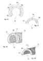
- Figures 1g, 1h, 1i and 1j show examples of such embodiments at one and more Protective casing segments, in any configuration, arrangement and combination options.
- Fig. 1g shows a semicircular protective sheath segment, in combination of smoother and accordion-shaped training, with the accordion-trained Sections are perpendicular.
- Fig. 1h and Fig. 1i show two semicircular protective sheath segments.
- Fig. 1h shows an example of two protective shell segments in smooth training, which the Protection of straight sections of one and more lines are suitable.
- Fig. 1i shows an example of two protective shell segments, in accordion-shaped Training, vertical, with smoothly formed end faces, which for protection of sections of one and several lines with any curve shape are suitable.
- Fig. 1j shows two semicircular protective sheath segments, in accordion-shaped Training, run vertically, with smooth training of the ends or end faces.
- the shape of the semicircle becomes more protective shell segments preferred, which are designed to be movable, e.g. accordion-shaped, wavy and preferably ends at the ends or at the ends in a smooth training.
- Protective jacket for a protective jacket, for several protective coats and for any desired Number of protective shell segments stand.
- the protective sheath may be provided with one and / or more spacers, wherein then the protective sheath and a spacer and / or more Spacers each on the line or lines to be protected, again detachable be plugged and circumferentially surrounded to be protected line or lines and at least along a portion of the conduit (s) between protective conduit or lines and the protective sheath a cavity (Safety distance) is generated.
- a spacer and / or a plurality of spacers be present, which from any body shape and / or more arbitrary Body shapes can be executed or can, whichever or arbitrarily on or placed in a protective jacket and secured in any way, as well as factory incorporated, factory pre-assembled or can be for assembly.
- the spacer and / or the spacers is characterized in that this or this along a portion of the line or lines, between the Line or the cables and the protective jacket, in the assembled state, a cavity (Safety distance), any measure, generated or generate. Where the bearing surface or bearing surfaces of the spacer and / or the spacers mounted in the Condition the line does not necessarily have to touch.
- Figures 2a, 2b, 2c, 2d, 2e, 2f, 2g, 2h, 2i and 2j show only a small number of examples the numerous possible embodiments of one and / or more spacers, 2f, 2h and 2j show a perspective view and a bottom view, respectively, of FIG. 2e, FIG. 2g and 2i show.
- Fig. 2a and Fig. 2c each show a spacer.
- This embodiment of the Spacer has at least one clip ring 12, which in any form, e.g. a semicircle (Figure 2c), quarter-arch, arched, C-shaped ( Figure 2a), Ellipse-shaped, semi-elliptical, in regular and irregular polygons may be executed with at least one or more spacer ribs 13 with an outer investor ring 14, which in any form e.g. a semicircle ( Figure 2c), Quarter arc, Arc-shaped, C-shaped ( Figure 2a), Ellipse-shaped, Semi-elliptical, in regular and irregular polygons can be executed and one Receiving opening 15 for mounting on the line to be protected or on the zu owns protective lines.
- Figs. 2b and 2d each show a spacer.
- This embodiment of the Spacer has at least one clip ring 12, which in any form, e.g. a semicircle (Figure 2d), quarter-arch, arched, C-shaped ( Figure 2b), Ellipse-shaped, semi-elliptical, in regular and irregular polygons can be executed with at least one or more spacer ribs 13 directly in the inside of the and / or in the protective jacket 11 (without investor ring 14) is mounted and has a receiving opening 15 for mounting.
- Figures 2e and 2g show another embodiment of a plurality of spacers 16, which consist of several arbitrarily shaped bodies, here e.g. in the form of Rectangles ( Figure 2e) and cylinders ( Figure 2g).
- the arbitrarily shaped bodies can or in the inside of the protective jacket 11, vertically, horizontally or diagonally be arranged.
- the bearing surface or Support surfaces 17 may be slightly curved in shape to an optimal Adaptation to the line to be protected or to the lines to be protected obtained, the bearing surface or the bearing surfaces, the line to be protected or do not have to touch lines.
- Fig. 2i shows another embodiment, a spacer, in any body shape running on the inside of the protective jacket 11, here e.g. in the form of a half ellipse 16. Wherein the running body, the bearing surfaces 17 to the line to be protected or forms the lines to be protected, but this must not touch.
- Fig. 2f shows the bottom view of Fig. 2e
- Fig. 2h shows the bottom view of Fig. 2g
- Fig. 2j shows the bottom view of Fig. 2i.
- Fig. 3p shows a variant, the preferred embodiments, of several Standoffs.
- Fig. 3p shows two spacers 16, each consisting of a square body on the inside of the protective jacket 11 extending.
- the line protection device to the numerous cable diameter of the line or lines to be protected solve, without being specific to the numerous cable diameter and the respective Specific properties to manufacture its own line protection device, it is of Advantage to provide a device which an individual adaptation to the Different cable diameters possible.
- the preferred embodiment of the line protection device includes one or more Spacers and one or more devices for individual adaptation to the most different cable diameters.
- the device comes for customization to use when the outside diameter of the too protective wire or lines, not the inner diameter of the Protective device (protective sheath with spacer).
- this device for individual adaptation to a wide variety Diameter, e.g. by adding or releasing this device the need Diameter set and / or by one or more built-in or factory preassembled or to be attached devices which, when mounting the Line protection device, by the volume of the line to be protected Mechanism triggers or this device changed so that the Line protection device, on the line to be protected or the lines fixed becomes.
- the device for individual adaptation to a variety of diameters is not needed, ie this is not mounted or removed when this is detachably pre-assembled.
- the circuit protection device (protective sheath with spacer) is to be mounted alone, wherein the support surface of the spacer or spacers has direct contact with the line to be protected.
- the device for individual adaptation to a wide variety of diameters is not releasably attached, it is always used.
- the device for individual adaptation to a wide variety of diameters or the devices for individual adaptation to the most diverse Diameter characterized in that this is an individual adaptation and Fixation of the line protection device or line protection devices to the different pipe diameters and their respective specific properties, allows the protected line or lines.
- the device or the devices for individual adaptation to a wide variety of diameters executed in any way, arbitrarily arranged, arbitrary at or in all Placed elements of this line protection device or line protection devices and can be attached or can, as well as factory incorporated, factory pre-assembled or for assembly.
- a device or devices may be present or which allows a certain function.
- This device or Attachment devices may be made in any manner, arranged arbitrarily, arbitrarily in or on all elements of this line protection device or line protection devices are placed and fixed, as well as factory incorporated, factory pre-assembled or can be included in the assembly.
- a possible embodiment of a device or devices for individual adaptation to a wide variety of diameters may consist of several arbitrarily shaped body, which on or inside the protective jacket and / or on or in the spacer and / or on or in the spacers, again detachable , be placed in any order eg vertical, diagonal, horizontal.
- the attachment of the individual body can be done in any way.
- the inner diameter is individually reduced or increased, thus allowing an individual diameter adjustment.
- FIG. 3a shows an example of such an embodiment of a device for individual adaptation to a variety of diameters in the mounted state, to be protected line 18, consisting of rectangular shaped bodies 19, preferably in an arcuate design of the support surface 24, for a better fit to to get the protected line or on the lines.
- a plug-in system (Fig. 3b)
- Fig. 3c a sliding system
- the spacer or protective sheath here diagonal, for example become.
- a device or devices for individual adaptation to the most diverse diameters can be made from the Use of one or more flexible or elastic materials and / or of non-elastic materials, which received an elasticity by the shaping or received.
- the flexible or elastic material or the shaping with elastic property in each case at the ends on or in the spacer and / or in or on the spacers and / or on or in the inside of the protective jacket placed.
- the embodiment of a Device for individual adaptation to a wide variety of diameters which in the line protection device runs through the volume of the line or the Lines, pressed in the direction of the protective jacket. By the resulting tension is the line protection device, fixed to the line or lines to be protected.
- the attachment of this device on or in the protective jacket and / or on or in one Spacers and / or on or in the spacers can in any way be made, factory-incorporated, factory pre-assembled or for assembly accompanied.
- Figures 3d, 3e, 3f, 3g and 3h show examples of such embodiments of a device or of devices for individual adaptation to the most diverse Diameter.
- Fig. 3d shows two attached protective sheath segments 11, with two Spacers 16, which on the inside of each protective casing segment 11th run.
- the spring or the device for individual adaptation to the most diverse diameter 19, can be additional with a bearing surface, of any shape, e.g. here in the form of a rectangle 25, in a slightly curved shape Training, be provided. If no additional support surface is incorporated, make the two springs, even the bearing surface is, in each case with the area which the protective line touched.
- attachment of this device to the individual Adaptation to a wide variety of diameters can be on or in the protective jacket and / or on or in the spacer and / or on or in the spacers be made in any way, as well as factory incorporated, factory pre-assembled or enclosed with the assembly.
- FIG. 3e, 3f and 3g show further shapes with elastic property.
- Fig. 3e shows a helical compression spring
- Fig. 3f shows a helical tension spring
- Fig. 3g shows Material in corrugated form.
- Fig. 3h shows an example of a usable elastic material, in the embodiment a broad rubber.
- a device or devices for individual adaptation to the most diverse diameters can consist of several consist of arbitrarily shaped bodies, which on one side, on or in one Spacers and / or in or on the spacers and / or in or on Protective jacket, to be placed.
- the attachment can be done in any way, also incorporated at the factory, factory pre-assembled or enclosed with the assembly.
- the other side of or the arbitrarily shaped body ends freely, in the inner life of Line protection device. Under the condition that in the assembled state, the Line protection device, the body, with the free-ending side or surface, with the zu protective line or the lines makes a contact.
- volume of too protective line will be the embodiment of a device for individual adaptation to the most varied diameters by the volume of Line or lines, pressed in the direction of the protective jacket.
- the resulting voltage is the line protection device on the line to be protected or fixed to the pipes.
- 3i, 3j, 3k and 3l show examples of such embodiments, a device or of devices for individual adaptation to a wide variety of diameters, of which Fig. 3j and 3l show a detail view.
- 3i shows a side view or detailed view of two protective shell segments 11, with two spacers 16, mounted on a line 18 to be protected.
- the Device for individual adaptation to a wide variety of diameters 19, here consisting of two flexible bodies, each in the form of a rectangle an angled end and a slightly curved pronounced end.
- the angled end is on or in the spacer and / or on or in the Spacers 16 and / or attached to or in the protective jacket by plugging.
- the end with arcuate expression ends freely in the inner workings of the Line protection device.
- No. 24 shows, the respective bearing surface, which in mounted state, by the volume of the line to be protected, respectively in the direction 47 of the protective jacket or in the direction of the line protection device is pressed. Due to the resulting voltage, the entire line protection device is connected to the fixed protective wire.
- Fig. 3j shows a detail view of the body, in the form of a rectangle, with a light arched pronounced end.
- 3k shows a side view or detail view of two protective shell segments 11, with two spacers 16, in the assembled state, without protecting Management.
- the device for individual adaptation to the most diverse Diameter here consisting of two parallel mounted bending springs 19, each on one side on or in the spacer and / or on or in the Spacers and / or be placed on or in the protective jacket and in the assembled state freely in the interior of the line protection device ends.
- the two bending springs by the volume of the to be protected line or lines, respectively in the direction 47 of the protective jacket or pressed in the direction of the line protection device.
- the entire line protection device is on the line to be protected fixed.
- the attachment of the device for individual adaptation to the different diameters, of which any number can be used can be made in any way, as well as factory-incorporated, factory pre-assembled or included with the assembly.
- Fig. 3l shows a detailed view of a bending spring.
- a device or devices for individual adaptation to the most diverse diameters can consist of several arbitrarily shaped and flexible bodies are made, each on one side on or in the spacer and / or on or in the spacers and / or on or in the Protective jacket, can be attached in any way, as well as factory pre-assembled, factory-incorporated or can be supplied for assembly.
- Preferably four arbitrarily shaped body a unit, a device for individual adaptation represent the most varied diameters and of this unit as many as you like can be used.
- any two molded and flexible bodies by means of one or more connecting device be provided to embrace the other body and / or any shape and shape flexible body be provided with one or more connecting devices.
- the two bodies by their respective or respective Connecting devices, which in the assembled state above and below the to be protected line or lines, by the volume of the line or the lines give a voltage, in turn, a fixation to the different diameter of a protective line or lines allows.
- Fig. 3m shows an example of such an embodiment of a device for individual adaptation to a wide variety of diameters.
- Fig. 3m shows a side view of two protective shell segments 11, with two Spacers 16, in the assembled state, without line to be protected.
- a device or of Devices for individual adaptation to a variety of diameters can consist of several flexible or elastic materials, in any body shape.
- the arbitrarily shaped bodies are each at the ends on or in the spacer and / or on or in the spacers and / or on or in the inside of the Protective sheath and / or by means of a special device or devices that themselves in or on the spacer and / or in or on the spacers and / or on or is in the protective jacket, so attached or attached that in the assembled state, the flexible or elastic body that touches to be protected line or lines.
- the line protection device When mounting the line protection device is the embodiment of a device or the devices for individual adaptation to the most diverse Diameter, which runs in the line protection device, by the volume of Line, pressed in the direction of the protective sheath, with the ends of the or any shaped bodies that can maintain position and / or change their position. Due to the resulting voltage, the line protection device to which fixed protective wire.
- the attachment of this device or devices For individual adaptation to a wide variety of diameters can be on every kind Way, as well as a special or additional device or devices include for attachment, which allows a specific function. Of this Device for individual adaptation to a variety of diameters, can Any number of uses, as well as factory incorporated, factory pre-assembled or included with the assembly.
- Figs. 3n, 3o and 3p show examples of such preferred embodiments of a Device or devices for individual adaptation to the different diameters.
- Fig. 3n shows a side view of two protective shell segments 11, with two Spacers 16, each consisting of a square body, here at the Inside, the respective protective casing segment 11 running, in the mounted state, on a line to be protected 18.
- This device for stationary Attachment may e.g.
- a receiving device 27 which the Introduction and attachment of the device for individual adaptation to the different diameter allows without shortening or one Mobility of the ends of the flexible body requires and / or by means of insertion holes (Fig. 3o no. 28), which at one end or the ends of the flexible bodies a mobility, at least one end presupposes that a time-white shortening of a or a plurality of ends to the fastening or insertion into the insertion holes and the decrease allows.
- Fig. 3o no. 28 which at one end or the ends of the flexible bodies a mobility, at least one end presupposes that a time-white shortening of a or a plurality of ends to the fastening or insertion into the insertion holes and the decrease allows.
- the device for individual adaptation to the most varied diameters by means of hoes, eyelets or the like, so that the ends can be fixed stationary.
- Fig. 3p shows a side view of two protective casing segments 11, with two spacers 16, each consisting of a square body, run on the inside, the protective jacket 11, in the assembled state, on a line to be protected 18.
- the device for individual adaptation to the different diameter 19, in this embodiment consists of two flexible body, in a slight w-like training and arbitrary shaping of the ends, here in T-shaped configuration.
- one or more guide rails 29 are attached to fix the device for individual adaptation to the most varied diameters 19, which are placed arbitrarily on or in the spacer and / or on or in the spacers and / or on or in the inside of the protective jacket and can run continuously and / or in sections .
- the flexible body When using a continuous guide rail, the flexible body is inserted at the respective open ends of the guide rail. Are the guide rails only partially extending, the resulting space 31 can be used in addition to the assembly 30 of the flexible body by each compressed the ends of the flexible body, and positioned in the free space 30 and inserted into guide rails 29.
- the embodiment of a device for individual adaptation to the various diameters 19, which runs in the line protection device is pressed by the volume of the line 18 and the lines, in the direction of the protective jacket. Wherein the ends of the arbitrarily shaped body 19, change the position in the guide rail or guide notes and run in opposite directions. Due to the resulting voltage, the line protection device is fixed to the line to be protected. From this embodiment of a device for individual adaptation to a wide variety of diameters can be used as many, as well as factory pre-assembled or enclosed with the assembly.
- Fig. 4a and 4b show examples of factory-incorporated closure options.
- Figures 4d, 4e and 4f show examples of external closure options.
- Fig. 4c shows Figures 4d, 4e and 4f in the applied state.
- Fig. 4a shows an example of a preferred embodiment of a closure option, if several spacers are present, consisting of several Closure organs and mating closure organs, which preferably directly in or on the spacers incorporated and / or as an extension to the Spacers are attached.
- the respective closure member 32 has a latching nose 34 which is formed in the locking cage Counter-locking member 33 is introduced. To the closure member 32 and Counter-locking member 33 to release again, pressure is exerted on the locking lugs 34.
- Fig. 4b shows another embodiment of a closure option consisting of several closing organs and counter-occlusive organs, which on the outside of the Line protection device are arbitrarily positioned and mounted.
- the closure member 32 has a latching nose 34 which in the as a detent cage trained counter-locking member 33 is introduced.
- the closing organs and Counter-locking organs can be positioned anywhere on the protective jacket and in any way and manner, for example by means of a connection which a allows to pivot.
- Fig. 4c shows examples of externally mounted closure options on two Protective casing segments 11.
- No. 35 shows a possible closure variant by means Cable Whirl
- No. 36 shows a possible closure variant using cable ties and No. 37 by means of Velcro strips.
- Fig. 4f shows a detail view of a cable cutter corresponding to No. 35.
- Fig. 4d shows a Detail view of a cable tie, corresponding to No. 36.
- FIG. 4e shows a detail view of a Velcro tape, corresponding to No. 37.
- the protective jacket and / or the protective coats and / or Protective casing segments and the selected closure variant or their placement it may be advantageous to use the protective sheath and / or the protective sheaths and / or the Protective shell segments to be provided with a device which a lateral prevents slipping.
- This device which prevents slipping sideways, can in every way and Be executed manner and find as many uses and is characterized characterized in that this a lateral slipping or unfolding the Line protection device prevents or prevent.
- Fig. 5a and 5b show examples of such a device, which is a lateral prevents slipping.
- Fig. 5a shows a detailed views of two protective shell segments 11. Wherein ein Protective casing segment on the longitudinal edge one or more extensions in the form of a Pin or stabilizing pin 38 and wherein the other protective sheath segment on the gegenübudge body or bodies has a counter-recess 39 or have.
- the stabilizing pin or pins 38 in FIG the opposite counter-indentations or counter-indentations 39 introduced.
- Fig. 5b shows a detailed views of two protective shell segments 11. Wherein ein Protective casing segment along the longitudinal edge, on the outside and / or inside of the Protective jacket segment one or more stabilizing pins 38, in any length and having or having shape. After mounting the line protection device, prevents this stabilizing pin 38 and this stabilizing pins a lateral slip and bring during assembly the advantage that no accurate insertion into a counter-recess or counter-recesses is required.
- One of the other options would be to attach several stabilizer pins to the respective one Longitudinal edges of a protective jacket and / or protective coats and / or of To install protective sheath segments.
- Fig. 5c shows two interconnected protective sheath segments 11, wherein a Protective casing segment here with an externally mounted stabilizing pin 38, in the Center of the line protection device length is provided.
- Figures 6a, 6b, 6c and 6d show examples of possible embodiments of such Device for juxtaposing or connecting adjacent, immediate adjacent protective sheaths and / or protective sheath segments.
- FIGS. 6a and 6b show an example of a detail view of two each with one another connected protective sheath segments 11, which on the front side of the Sheath segments a device for connecting adjacent, immediate have adjacent protective shells and / or protective sheath segments.
- Fig. 6a shows two interconnected protective sheath segments 11, which at one end face with Any number of lugs 40 are provided.
- Fig. 6b shows two interconnected Protective casing segments 11, which at one end face with as many Counter-depressions, the nose shape 41, are provided.
- Fig. 6a and 6b are through Merging the lugs 40 and the respective counter-depression in nose shape 41st connected with each other.
- Fig. 6c and Fig. 6d shows an example of a detail view of two each with each other connected protective sheath segments 11, which on the front side of the Sheath segments a device for connecting adjacent, immediate have adjacent protective shells or protective sheath segments.
- Fig. 6c shows several closure members, each with a latching lug 42.
- Fig. 6d has several Counter locking members 43 in the form of a cage, for locking the locking lug on.
- the Locking organs with locking lug 42 and the counter-locking members 43 can be arbitrary placed and fastened in any way, as well as pivoted e.g. by means of Pin connections 44 or fixed firmly.
- the To provide line protection device which are characterized that the special finishing protective sheaths and / or the finishing sheath segments, in any length and diameter design, in any body shape e.g. one Semicircle, quarter-arch, arched, C-shaped, elliptical, semi-elliptical, Unround, in regular and irregular polygons can be executed, where the protective covers and / or the protective cover segments of any kind formed e.g. accordion-shaped, wavy, smooth, cross-ribbed, trapezoidal, rectangular and these formations may run in any arrangement, e.g. vertical, horizontal, diagonal.
- the special finishing protective sheaths and / or the finishing sheath segments in any length and diameter design, in any body shape e.g. one Semicircle, quarter-arch, arched, C-shaped, elliptical, semi-elliptical, Unround, in regular and irregular polygons
- the training, the arrangement, the length and diameter are executed can. But where no spacer or spacers and / or no Device or devices for individual adaptation to the most diverse Line diameter must be included.
- any type of attachment is possible, which is one Stringing together or a connection allows.
- this Attachment which allows a lining or a connection, it can be necessary to prevent sufficient stability or solving these too End guards and / or the end guards segments with a To provide device which allows a connect or close together.
- Figs. 7a, 7b, 7c and 7d show examples of possible embodiments of several End protective shell segments and examples of mounting options for Stringing together adjacent, immediately adjacent protective sheath or adjacent protective shell segments and examples of a device of each other close.
- FIG. 7 a shows two end protection shell segments 45, in combination of FIG accordion-shaped and smooth training, in body form of a semicircle.
- a Front side is a device which the juxtaposing, adjacent to directly adjacent protective casing or of adjacent protective casing segments, in the form of noses 40, allows.
- the adjacent one Protective jacket or the adjacent protective shell segments counter-recesses in the This nose shape, number and positioning include.
- the two end shield shell segments 45 of FIG. 7a show two examples of one Device of closing together, on the longitudinal edge of the Final protective coating segments.
- No. 32 shows a closure member with latching nose 34, which by insertion into the counter-locking member 33, the two End protection shell segments connects or closes.
- No. 40 shows one Nose, which by insertion into the counter-recess 41, the two End protection shell segments connects or closes.
- Fig. 7b shows two end protection shell segments 45, in accordion-shaped Training and horizontal, slightly diagonal arrangement, in body shape Semicircle, which has a diameter reduction on one end face.
- Fig. 7c shows a final protective sheath segment 45, in a smooth configuration, in body shape a semicircle, which on a front side a diameter reduction and on the another end, a device which the juxtaposing, on adjacent immediately adjacent protective sheath or of adjacent protective sheath segments has, in the form of noses, in an angular shape 40th
- Fig. 7d shows a cover shell segment 45, in accordion-like design and vertical arrangement or vertically extending, in the form of a semi-circle, which has a diameter reduction on one end face.
- a cover shell segment 45 in accordion-like design and vertical arrangement or vertically extending, in the form of a semi-circle, which has a diameter reduction on one end face.
- Fig. 8 shows an example of such an embodiment, a device with Hinge-like property, on two semi-circular body shapes 11, which by means of an embossment 48, here of the same material, movably connected are.
- the line protection device or line protection devices with their many Variation possibilities and elements can additionally with air vents or Ventilation chambers and / or perforations, of any shape, of any size and Arrangement, be provided.
- Fig. 3p shows an example of incorporated ventilation slots 46th
- this one Line protection device or line protection devices may or may any suitable material or materials and material combinations, as well as in any Coloring, shading and color combinations are produced.
Applications Claiming Priority (2)
| Application Number | Priority Date | Filing Date | Title |
|---|---|---|---|
| DE102004018313A DE102004018313A1 (de) | 2004-04-13 | 2004-04-13 | Leitungsschutzvorrichtung |
| DE102004018313 | 2004-04-13 |
Publications (3)
| Publication Number | Publication Date |
|---|---|
| EP1587193A2 true EP1587193A2 (fr) | 2005-10-19 |
| EP1587193A3 EP1587193A3 (fr) | 2006-08-02 |
| EP1587193B1 EP1587193B1 (fr) | 2010-06-16 |
Family
ID=34585430
Family Applications (1)
| Application Number | Title | Priority Date | Filing Date |
|---|---|---|---|
| EP05005776A Not-in-force EP1587193B1 (fr) | 2004-04-13 | 2005-03-16 | Dispositif protecteur de câble |
Country Status (3)
| Country | Link |
|---|---|
| EP (1) | EP1587193B1 (fr) |
| AT (1) | ATE471587T1 (fr) |
| DE (2) | DE102004018313A1 (fr) |
Cited By (2)
| Publication number | Priority date | Publication date | Assignee | Title |
|---|---|---|---|---|
| CN103298661A (zh) * | 2010-12-28 | 2013-09-11 | 矢崎总业株式会社 | 线束和线束的制造方法 |
| US20230020124A1 (en) * | 2021-06-28 | 2023-01-19 | Nexans | Vibration damper |
Families Citing this family (2)
| Publication number | Priority date | Publication date | Assignee | Title |
|---|---|---|---|---|
| ES2258934B1 (es) * | 2005-12-09 | 2007-06-16 | Tom Hutchinson | Elemento de proteccion local de cables. |
| DE102020005082B3 (de) | 2020-09-02 | 2021-10-14 | G-quadrat Geokunststoffgesellschaft mbH | Flexible Textilstruktur, Bodenbauelement mit einer flexiblen Textilstruktur, Verfahren zur Herstellung eines Bodenbauelements, Erdleitungs-Schutzsystem und Verfahren zur Herstellung eines Erdleitungs-Schutzsystems sowie Verwendung des Bodenbauelements |
Citations (11)
| Publication number | Priority date | Publication date | Assignee | Title |
|---|---|---|---|---|
| DE1881159U (de) * | 1963-07-18 | 1963-10-24 | E Vogelsang Fa Dipl Ing Dr | Kabelschutzrohr. |
| FR1344705A (fr) * | 1963-01-16 | 1963-11-29 | Atlas Copco Ab | Dispositif de montage et de soutien pour câbles électriques |
| GB2009523A (en) * | 1977-09-13 | 1979-06-13 | Owen W J | Improvements relating to trunking systems for conduits or cables |
| FR2591306A1 (fr) * | 1985-12-09 | 1987-06-12 | Bourreau Bruno | Procede pour la realisation d'un reseau fixe de transport de fluide dans un batiment, dispositif de guidage et de maintien pour la realisation d'un tel reseau, et reseau obtenu par ce procede |
| US5800762A (en) * | 1996-12-06 | 1998-09-01 | Bethel; Eunice A. | Process for decorating electrical cords |
| EP0887902A2 (fr) * | 1997-06-28 | 1998-12-30 | T&N TECHNOLOGY LIMITED | Enveloppe de protection flexible |
| DE19751611A1 (de) * | 1996-06-05 | 1999-05-27 | Georg Krain | Folien ummantelte Installationskanäle und Lichtblenden |
| DE10031692A1 (de) * | 2000-06-29 | 2002-01-10 | Alsta Aluminium Und Stahl Gmbh | Stecksystem |
| GB2365941A (en) * | 2000-08-16 | 2002-02-27 | Balmoral Group | Protective sleeving |
| WO2002054553A2 (fr) * | 2001-01-02 | 2002-07-11 | Barry Howard | Installation de cable et composants associes |
| DE10139740C1 (de) * | 2001-08-13 | 2003-04-17 | Schlemmer Gmbh | Rohrverbindungsteil für Wellrohre mit innenliegendem Dämpfungselement |
-
2004
- 2004-04-13 DE DE102004018313A patent/DE102004018313A1/de not_active Withdrawn
-
2005
- 2005-03-16 AT AT05005776T patent/ATE471587T1/de active
- 2005-03-16 DE DE502005009742T patent/DE502005009742D1/de active Active
- 2005-03-16 EP EP05005776A patent/EP1587193B1/fr not_active Not-in-force
Patent Citations (11)
| Publication number | Priority date | Publication date | Assignee | Title |
|---|---|---|---|---|
| FR1344705A (fr) * | 1963-01-16 | 1963-11-29 | Atlas Copco Ab | Dispositif de montage et de soutien pour câbles électriques |
| DE1881159U (de) * | 1963-07-18 | 1963-10-24 | E Vogelsang Fa Dipl Ing Dr | Kabelschutzrohr. |
| GB2009523A (en) * | 1977-09-13 | 1979-06-13 | Owen W J | Improvements relating to trunking systems for conduits or cables |
| FR2591306A1 (fr) * | 1985-12-09 | 1987-06-12 | Bourreau Bruno | Procede pour la realisation d'un reseau fixe de transport de fluide dans un batiment, dispositif de guidage et de maintien pour la realisation d'un tel reseau, et reseau obtenu par ce procede |
| DE19751611A1 (de) * | 1996-06-05 | 1999-05-27 | Georg Krain | Folien ummantelte Installationskanäle und Lichtblenden |
| US5800762A (en) * | 1996-12-06 | 1998-09-01 | Bethel; Eunice A. | Process for decorating electrical cords |
| EP0887902A2 (fr) * | 1997-06-28 | 1998-12-30 | T&N TECHNOLOGY LIMITED | Enveloppe de protection flexible |
| DE10031692A1 (de) * | 2000-06-29 | 2002-01-10 | Alsta Aluminium Und Stahl Gmbh | Stecksystem |
| GB2365941A (en) * | 2000-08-16 | 2002-02-27 | Balmoral Group | Protective sleeving |
| WO2002054553A2 (fr) * | 2001-01-02 | 2002-07-11 | Barry Howard | Installation de cable et composants associes |
| DE10139740C1 (de) * | 2001-08-13 | 2003-04-17 | Schlemmer Gmbh | Rohrverbindungsteil für Wellrohre mit innenliegendem Dämpfungselement |
Cited By (2)
| Publication number | Priority date | Publication date | Assignee | Title |
|---|---|---|---|---|
| CN103298661A (zh) * | 2010-12-28 | 2013-09-11 | 矢崎总业株式会社 | 线束和线束的制造方法 |
| US20230020124A1 (en) * | 2021-06-28 | 2023-01-19 | Nexans | Vibration damper |
Also Published As
| Publication number | Publication date |
|---|---|
| DE502005009742D1 (de) | 2010-07-29 |
| DE102004018313A1 (de) | 2005-06-16 |
| EP1587193B1 (fr) | 2010-06-16 |
| EP1587193A3 (fr) | 2006-08-02 |
| ATE471587T1 (de) | 2010-07-15 |
Similar Documents
| Publication | Publication Date | Title |
|---|---|---|
| DE60019475T2 (de) | Kabelbaumschaumschutz der über die Kabel einrastet | |
| EP1729388B1 (fr) | Dispositif de fixation d'une ligne | |
| EP0713277B1 (fr) | Logement avec dispositif de retenue des câbles de connexion | |
| DE112013003678B4 (de) | Draht-Schutzelement | |
| DE10050565A1 (de) | Kabelbaum-Abwinkelvorrichtung | |
| WO2012168320A1 (fr) | Élément support de câble | |
| DE60025752T2 (de) | Fahrzeug-teppichanordnung mit rohrleitung | |
| EP1587193B1 (fr) | Dispositif protecteur de câble | |
| DE112019002841T5 (de) | Kabelbaum | |
| EP1746697B1 (fr) | Elément de fixation pour fixer une boîte à une canalisation à fils | |
| DE112013004193T5 (de) | Führungsstruktur für elektrische Leitungen | |
| EP0535712B1 (fr) | Faisceau de câble ou puits à câbles, particulièrement pour une voiture automobile | |
| DE102009030798A1 (de) | Schutzvorrichtung für flexible Elemente | |
| DE102005046194B4 (de) | Kabelkanal mit Kanalsegmenten | |
| DD265449A1 (de) | Kabel- und schlauchschlepp | |
| DE3634695C2 (fr) | ||
| EP1119087B1 (fr) | Boíte d'encastrement pour canalisations de câbles | |
| DE3545517C2 (fr) | ||
| DE102014004931A1 (de) | Abstandshalteeinrichtung | |
| EP1000783A1 (fr) | Ventilateur radial avec raccord de connexion | |
| DE102016112758B4 (de) | Halteteil und verfahren zum befestigen von elektrischen leitungen sowie leitungsanordnung in einem fahrzeug | |
| DE202014101359U1 (de) | Endbefestigungsteil für Leitungsführungseinrichtung | |
| DE60107309T2 (de) | System um Röhren, Schläuche oder andere Leitungen in einer Straßenoberfläche zu befestigen | |
| DE102018109476A1 (de) | Kabelhalter | |
| EP0954078B1 (fr) | Support pour au moins un câble ou un conduit |
Legal Events
| Date | Code | Title | Description |
|---|---|---|---|
| PUAI | Public reference made under article 153(3) epc to a published international application that has entered the european phase |
Free format text: ORIGINAL CODE: 0009012 |
|
| AK | Designated contracting states |
Kind code of ref document: A2 Designated state(s): AT BE BG CH CY CZ DE DK EE ES FI FR GB GR HU IE IS IT LI LT LU MC NL PL PT RO SE SI SK TR |
|
| AX | Request for extension of the european patent |
Extension state: AL BA HR LV MK YU |
|
| PUAL | Search report despatched |
Free format text: ORIGINAL CODE: 0009013 |
|
| AK | Designated contracting states |
Kind code of ref document: A3 Designated state(s): AT BE BG CH CY CZ DE DK EE ES FI FR GB GR HU IE IS IT LI LT LU MC NL PL PT RO SE SI SK TR |
|
| AX | Request for extension of the european patent |
Extension state: AL BA HR LV MK YU |
|
| 17P | Request for examination filed |
Effective date: 20070202 |
|
| AKX | Designation fees paid |
Designated state(s): AT BE BG CH CY CZ DE DK EE ES FI FR GB GR HU IE IS IT LI LT LU MC NL PL PT RO SE SI SK TR |
|
| GRAP | Despatch of communication of intention to grant a patent |
Free format text: ORIGINAL CODE: EPIDOSNIGR1 |
|
| GRAS | Grant fee paid |
Free format text: ORIGINAL CODE: EPIDOSNIGR3 |
|
| GRAA | (expected) grant |
Free format text: ORIGINAL CODE: 0009210 |
|
| AK | Designated contracting states |
Kind code of ref document: B1 Designated state(s): AT BE BG CH CY CZ DE DK EE ES FI FR GB GR HU IE IS IT LI LT LU MC NL PL PT RO SE SI SK TR |
|
| REG | Reference to a national code |
Ref country code: CH Ref legal event code: EP |
|
| REG | Reference to a national code |
Ref country code: IE Ref legal event code: FG4D Free format text: LANGUAGE OF EP DOCUMENT: GERMAN |
|
| REF | Corresponds to: |
Ref document number: 502005009742 Country of ref document: DE Date of ref document: 20100729 Kind code of ref document: P |
|
| REG | Reference to a national code |
Ref country code: NL Ref legal event code: VDEP Effective date: 20100616 |
|
| PG25 | Lapsed in a contracting state [announced via postgrant information from national office to epo] |
Ref country code: SE Free format text: LAPSE BECAUSE OF FAILURE TO SUBMIT A TRANSLATION OF THE DESCRIPTION OR TO PAY THE FEE WITHIN THE PRESCRIBED TIME-LIMIT Effective date: 20100616 Ref country code: LT Free format text: LAPSE BECAUSE OF FAILURE TO SUBMIT A TRANSLATION OF THE DESCRIPTION OR TO PAY THE FEE WITHIN THE PRESCRIBED TIME-LIMIT Effective date: 20100616 |
|
| LTIE | Lt: invalidation of european patent or patent extension |
Effective date: 20100616 |
|
| PG25 | Lapsed in a contracting state [announced via postgrant information from national office to epo] |
Ref country code: FI Free format text: LAPSE BECAUSE OF FAILURE TO SUBMIT A TRANSLATION OF THE DESCRIPTION OR TO PAY THE FEE WITHIN THE PRESCRIBED TIME-LIMIT Effective date: 20100616 Ref country code: SI Free format text: LAPSE BECAUSE OF FAILURE TO SUBMIT A TRANSLATION OF THE DESCRIPTION OR TO PAY THE FEE WITHIN THE PRESCRIBED TIME-LIMIT Effective date: 20100616 |
|
| PG25 | Lapsed in a contracting state [announced via postgrant information from national office to epo] |
Ref country code: CY Free format text: LAPSE BECAUSE OF FAILURE TO SUBMIT A TRANSLATION OF THE DESCRIPTION OR TO PAY THE FEE WITHIN THE PRESCRIBED TIME-LIMIT Effective date: 20100616 Ref country code: PL Free format text: LAPSE BECAUSE OF FAILURE TO SUBMIT A TRANSLATION OF THE DESCRIPTION OR TO PAY THE FEE WITHIN THE PRESCRIBED TIME-LIMIT Effective date: 20100616 Ref country code: GR Free format text: LAPSE BECAUSE OF FAILURE TO SUBMIT A TRANSLATION OF THE DESCRIPTION OR TO PAY THE FEE WITHIN THE PRESCRIBED TIME-LIMIT Effective date: 20100917 |
|
| REG | Reference to a national code |
Ref country code: IE Ref legal event code: FD4D |
|
| PG25 | Lapsed in a contracting state [announced via postgrant information from national office to epo] |
Ref country code: IE Free format text: LAPSE BECAUSE OF FAILURE TO SUBMIT A TRANSLATION OF THE DESCRIPTION OR TO PAY THE FEE WITHIN THE PRESCRIBED TIME-LIMIT Effective date: 20100616 Ref country code: NL Free format text: LAPSE BECAUSE OF FAILURE TO SUBMIT A TRANSLATION OF THE DESCRIPTION OR TO PAY THE FEE WITHIN THE PRESCRIBED TIME-LIMIT Effective date: 20100616 Ref country code: EE Free format text: LAPSE BECAUSE OF FAILURE TO SUBMIT A TRANSLATION OF THE DESCRIPTION OR TO PAY THE FEE WITHIN THE PRESCRIBED TIME-LIMIT Effective date: 20100616 |
|
| PG25 | Lapsed in a contracting state [announced via postgrant information from national office to epo] |
Ref country code: RO Free format text: LAPSE BECAUSE OF FAILURE TO SUBMIT A TRANSLATION OF THE DESCRIPTION OR TO PAY THE FEE WITHIN THE PRESCRIBED TIME-LIMIT Effective date: 20100616 Ref country code: SK Free format text: LAPSE BECAUSE OF FAILURE TO SUBMIT A TRANSLATION OF THE DESCRIPTION OR TO PAY THE FEE WITHIN THE PRESCRIBED TIME-LIMIT Effective date: 20100616 Ref country code: CZ Free format text: LAPSE BECAUSE OF FAILURE TO SUBMIT A TRANSLATION OF THE DESCRIPTION OR TO PAY THE FEE WITHIN THE PRESCRIBED TIME-LIMIT Effective date: 20100616 Ref country code: IS Free format text: LAPSE BECAUSE OF FAILURE TO SUBMIT A TRANSLATION OF THE DESCRIPTION OR TO PAY THE FEE WITHIN THE PRESCRIBED TIME-LIMIT Effective date: 20101016 Ref country code: PT Free format text: LAPSE BECAUSE OF FAILURE TO SUBMIT A TRANSLATION OF THE DESCRIPTION OR TO PAY THE FEE WITHIN THE PRESCRIBED TIME-LIMIT Effective date: 20101018 |
|
| PG25 | Lapsed in a contracting state [announced via postgrant information from national office to epo] |
Ref country code: IT Free format text: LAPSE BECAUSE OF FAILURE TO SUBMIT A TRANSLATION OF THE DESCRIPTION OR TO PAY THE FEE WITHIN THE PRESCRIBED TIME-LIMIT Effective date: 20100616 |
|
| PLBE | No opposition filed within time limit |
Free format text: ORIGINAL CODE: 0009261 |
|
| STAA | Information on the status of an ep patent application or granted ep patent |
Free format text: STATUS: NO OPPOSITION FILED WITHIN TIME LIMIT |
|
| PG25 | Lapsed in a contracting state [announced via postgrant information from national office to epo] |
Ref country code: DK Free format text: LAPSE BECAUSE OF FAILURE TO SUBMIT A TRANSLATION OF THE DESCRIPTION OR TO PAY THE FEE WITHIN THE PRESCRIBED TIME-LIMIT Effective date: 20100616 |
|
| 26N | No opposition filed |
Effective date: 20110317 |
|
| REG | Reference to a national code |
Ref country code: DE Ref legal event code: R097 Ref document number: 502005009742 Country of ref document: DE Effective date: 20110316 |
|
| BERE | Be: lapsed |
Owner name: KRAMER, KARL Effective date: 20110331 Owner name: MAKOHONENKO, MASCHA ALEXANDRA Effective date: 20110331 |
|
| PG25 | Lapsed in a contracting state [announced via postgrant information from national office to epo] |
Ref country code: MC Free format text: LAPSE BECAUSE OF NON-PAYMENT OF DUE FEES Effective date: 20110331 |
|
| REG | Reference to a national code |
Ref country code: CH Ref legal event code: PL |
|
| GBPC | Gb: european patent ceased through non-payment of renewal fee |
Effective date: 20110316 |
|
| REG | Reference to a national code |
Ref country code: FR Ref legal event code: ST Effective date: 20111130 |
|
| PG25 | Lapsed in a contracting state [announced via postgrant information from national office to epo] |
Ref country code: BE Free format text: LAPSE BECAUSE OF NON-PAYMENT OF DUE FEES Effective date: 20110331 |
|
| PG25 | Lapsed in a contracting state [announced via postgrant information from national office to epo] |
Ref country code: CH Free format text: LAPSE BECAUSE OF NON-PAYMENT OF DUE FEES Effective date: 20110331 Ref country code: DE Free format text: LAPSE BECAUSE OF NON-PAYMENT OF DUE FEES Effective date: 20111001 Ref country code: LI Free format text: LAPSE BECAUSE OF NON-PAYMENT OF DUE FEES Effective date: 20110331 Ref country code: FR Free format text: LAPSE BECAUSE OF NON-PAYMENT OF DUE FEES Effective date: 20110331 |
|
| REG | Reference to a national code |
Ref country code: DE Ref legal event code: R119 Ref document number: 502005009742 Country of ref document: DE Effective date: 20111001 |
|
| PG25 | Lapsed in a contracting state [announced via postgrant information from national office to epo] |
Ref country code: GB Free format text: LAPSE BECAUSE OF NON-PAYMENT OF DUE FEES Effective date: 20110316 |
|
| REG | Reference to a national code |
Ref country code: AT Ref legal event code: MM01 Ref document number: 471587 Country of ref document: AT Kind code of ref document: T Effective date: 20110316 |
|
| PG25 | Lapsed in a contracting state [announced via postgrant information from national office to epo] |
Ref country code: AT Free format text: LAPSE BECAUSE OF NON-PAYMENT OF DUE FEES Effective date: 20110316 |
|
| PG25 | Lapsed in a contracting state [announced via postgrant information from national office to epo] |
Ref country code: LU Free format text: LAPSE BECAUSE OF NON-PAYMENT OF DUE FEES Effective date: 20110316 |
|
| PG25 | Lapsed in a contracting state [announced via postgrant information from national office to epo] |
Ref country code: TR Free format text: LAPSE BECAUSE OF FAILURE TO SUBMIT A TRANSLATION OF THE DESCRIPTION OR TO PAY THE FEE WITHIN THE PRESCRIBED TIME-LIMIT Effective date: 20100616 Ref country code: BG Free format text: LAPSE BECAUSE OF FAILURE TO SUBMIT A TRANSLATION OF THE DESCRIPTION OR TO PAY THE FEE WITHIN THE PRESCRIBED TIME-LIMIT Effective date: 20100916 |
|
| PG25 | Lapsed in a contracting state [announced via postgrant information from national office to epo] |
Ref country code: ES Free format text: LAPSE BECAUSE OF FAILURE TO SUBMIT A TRANSLATION OF THE DESCRIPTION OR TO PAY THE FEE WITHIN THE PRESCRIBED TIME-LIMIT Effective date: 20100927 Ref country code: HU Free format text: LAPSE BECAUSE OF FAILURE TO SUBMIT A TRANSLATION OF THE DESCRIPTION OR TO PAY THE FEE WITHIN THE PRESCRIBED TIME-LIMIT Effective date: 20100616 |