EP1587193B1 - Dispositif protecteur de câble - Google Patents
Dispositif protecteur de câble Download PDFInfo
- Publication number
- EP1587193B1 EP1587193B1 EP05005776A EP05005776A EP1587193B1 EP 1587193 B1 EP1587193 B1 EP 1587193B1 EP 05005776 A EP05005776 A EP 05005776A EP 05005776 A EP05005776 A EP 05005776A EP 1587193 B1 EP1587193 B1 EP 1587193B1
- Authority
- EP
- European Patent Office
- Prior art keywords
- protection device
- line
- line protection
- protective
- springs
- Prior art date
- Legal status (The legal status is an assumption and is not a legal conclusion. Google has not performed a legal analysis and makes no representation as to the accuracy of the status listed.)
- Expired - Lifetime
Links
- 230000004224 protection Effects 0.000 title claims abstract description 81
- 230000001681 protective effect Effects 0.000 claims abstract description 151
- 125000006850 spacer group Chemical group 0.000 claims description 39
- 230000009975 flexible effect Effects 0.000 claims description 18
- 238000003780 insertion Methods 0.000 claims description 7
- 230000037431 insertion Effects 0.000 claims description 7
- 230000009183 running Effects 0.000 claims description 4
- 206010002515 Animal bite Diseases 0.000 claims description 2
- 238000007906 compression Methods 0.000 claims description 2
- 230000006835 compression Effects 0.000 claims description 2
- 229920001971 elastomer Polymers 0.000 claims description 2
- 239000005060 rubber Substances 0.000 claims description 2
- 230000037237 body shape Effects 0.000 abstract description 10
- 230000008859 change Effects 0.000 abstract description 5
- 241001465754 Metazoa Species 0.000 abstract description 3
- 230000003287 optical effect Effects 0.000 abstract description 3
- 230000006978 adaptation Effects 0.000 description 56
- 238000013461 design Methods 0.000 description 10
- 210000001331 nose Anatomy 0.000 description 9
- 238000012549 training Methods 0.000 description 9
- 230000000087 stabilizing effect Effects 0.000 description 7
- 239000013013 elastic material Substances 0.000 description 5
- 230000001788 irregular Effects 0.000 description 5
- 239000000463 material Substances 0.000 description 5
- 238000004519 manufacturing process Methods 0.000 description 4
- 238000005452 bending Methods 0.000 description 3
- 230000000669 biting effect Effects 0.000 description 3
- 230000009467 reduction Effects 0.000 description 3
- 238000009423 ventilation Methods 0.000 description 3
- 239000002826 coolant Substances 0.000 description 2
- 230000006378 damage Effects 0.000 description 2
- 230000001965 increasing effect Effects 0.000 description 2
- 230000013011 mating Effects 0.000 description 2
- 230000002829 reductive effect Effects 0.000 description 2
- 238000007493 shaping process Methods 0.000 description 2
- 238000004904 shortening Methods 0.000 description 2
- 241000282342 Martes americana Species 0.000 description 1
- 238000004378 air conditioning Methods 0.000 description 1
- 230000008901 benefit Effects 0.000 description 1
- 230000015572 biosynthetic process Effects 0.000 description 1
- 230000007423 decrease Effects 0.000 description 1
- 238000011161 development Methods 0.000 description 1
- 230000026058 directional locomotion Effects 0.000 description 1
- 238000004049 embossing Methods 0.000 description 1
- 210000001508 eye Anatomy 0.000 description 1
- 239000012530 fluid Substances 0.000 description 1
- 238000009472 formulation Methods 0.000 description 1
- 239000000446 fuel Substances 0.000 description 1
- 230000014509 gene expression Effects 0.000 description 1
- 238000002347 injection Methods 0.000 description 1
- 239000007924 injection Substances 0.000 description 1
- 238000005304 joining Methods 0.000 description 1
- 230000000670 limiting effect Effects 0.000 description 1
- 230000007246 mechanism Effects 0.000 description 1
- 239000000203 mixture Substances 0.000 description 1
- 238000000465 moulding Methods 0.000 description 1
- 230000003405 preventing effect Effects 0.000 description 1
- 230000001012 protector Effects 0.000 description 1
- 230000003578 releasing effect Effects 0.000 description 1
Images








Classifications
-
- F—MECHANICAL ENGINEERING; LIGHTING; HEATING; WEAPONS; BLASTING
- F16—ENGINEERING ELEMENTS AND UNITS; GENERAL MEASURES FOR PRODUCING AND MAINTAINING EFFECTIVE FUNCTIONING OF MACHINES OR INSTALLATIONS; THERMAL INSULATION IN GENERAL
- F16L—PIPES; JOINTS OR FITTINGS FOR PIPES; SUPPORTS FOR PIPES, CABLES OR PROTECTIVE TUBING; MEANS FOR THERMAL INSULATION IN GENERAL
- F16L57/00—Protection of pipes or objects of similar shape against external or internal damage or wear
-
- B—PERFORMING OPERATIONS; TRANSPORTING
- B60—VEHICLES IN GENERAL
- B60R—VEHICLES, VEHICLE FITTINGS, OR VEHICLE PARTS, NOT OTHERWISE PROVIDED FOR
- B60R16/00—Electric or fluid circuits specially adapted for vehicles and not otherwise provided for; Arrangement of elements of electric or fluid circuits specially adapted for vehicles and not otherwise provided for
- B60R16/02—Electric or fluid circuits specially adapted for vehicles and not otherwise provided for; Arrangement of elements of electric or fluid circuits specially adapted for vehicles and not otherwise provided for electric constitutive elements
- B60R16/0207—Wire harnesses
- B60R16/0215—Protecting, fastening and routing means therefor
-
- H—ELECTRICITY
- H02—GENERATION; CONVERSION OR DISTRIBUTION OF ELECTRIC POWER
- H02G—INSTALLATION OF ELECTRIC CABLES OR LINES, OR OF COMBINED OPTICAL AND ELECTRIC CABLES OR LINES
- H02G3/00—Installations of electric cables or lines or protective tubing therefor in or on buildings, equivalent structures or vehicles
- H02G3/02—Details
- H02G3/04—Protective tubing or conduits, e.g. cable ladders or cable troughs
- H02G3/0462—Tubings, i.e. having a closed section
- H02G3/0468—Corrugated
-
- H—ELECTRICITY
- H02—GENERATION; CONVERSION OR DISTRIBUTION OF ELECTRIC POWER
- H02G—INSTALLATION OF ELECTRIC CABLES OR LINES, OR OF COMBINED OPTICAL AND ELECTRIC CABLES OR LINES
- H02G3/00—Installations of electric cables or lines or protective tubing therefor in or on buildings, equivalent structures or vehicles
- H02G3/02—Details
- H02G3/04—Protective tubing or conduits, e.g. cable ladders or cable troughs
- H02G3/0462—Tubings, i.e. having a closed section
- H02G3/0481—Tubings, i.e. having a closed section with a circular cross-section
-
- H—ELECTRICITY
- H02—GENERATION; CONVERSION OR DISTRIBUTION OF ELECTRIC POWER
- H02G—INSTALLATION OF ELECTRIC CABLES OR LINES, OR OF COMBINED OPTICAL AND ELECTRIC CABLES OR LINES
- H02G3/00—Installations of electric cables or lines or protective tubing therefor in or on buildings, equivalent structures or vehicles
- H02G3/02—Details
- H02G3/04—Protective tubing or conduits, e.g. cable ladders or cable troughs
- H02G3/0462—Tubings, i.e. having a closed section
- H02G3/0487—Tubings, i.e. having a closed section with a non-circular cross-section
-
- H—ELECTRICITY
- H02—GENERATION; CONVERSION OR DISTRIBUTION OF ELECTRIC POWER
- H02G—INSTALLATION OF ELECTRIC CABLES OR LINES, OR OF COMBINED OPTICAL AND ELECTRIC CABLES OR LINES
- H02G3/00—Installations of electric cables or lines or protective tubing therefor in or on buildings, equivalent structures or vehicles
- H02G3/02—Details
- H02G3/06—Joints for connecting lengths of protective tubing or channels, to each other or to casings, e.g. to distribution boxes; Ensuring electrical continuity in the joint
Definitions
- the invention relates to a line protection device or line protection devices for the protection of one and more lines of any kind, in particular for the protection of the lines of motor vehicles and the daily life, against animal bite and / or for the general bundling of lines, of any kind and / or the wrapping of a and several lines, of any kind, for color change and optical beautification.
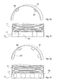
- the object is achieved by at least one protective sheath and / or multiple protective sheaths and / or multiple protective sheath segments, which or in any length and diameter design, in any body shape, for example, a semicircle ( Fig. 1a ), Quarter-arch, arched, C-shaped, elliptical, half-elliptical ( Fig. 1b ) , in regular and irregular polygons ( Fig. 1c ) can be executed or can.
- the protective sheath and / or the protective shells and / or the protective sheath segments can be formed in any way or can eg accordion ( Fig. 1d ), wavy ( Fig. 1e ), smooth ( Fig.
- transversely ribbed, trapezoidal ( Fig. 1f ), rectangular and these formations, can run in any order, for example, vertical, horizontal, diagonal.
- the protective sheath and / or the protective shells and / or the protective sheath segments in any combination or combinations of the body shape can be performed or can.
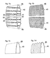
- Fig. 1g, 1h, 1i and 1j show examples of such embodiments on one and more protective shell segments, in any configuration, arrangement and combination options.
- Fig. 1g shows a semicircular protective sheath segment, in combination of smooth and concertina-shaped training, the accordion-shaped sections are perpendicular.
- Fig. 1h and Fig. 1i each show two semicircular protective sheath segments.
- Fig. 1h shows an example of two protective sheath segments in smooth training, which are suitable for the protection of straight sections of one and more lines.
- Fig. 1i shows an example of two protective shell segments, in concertina-shaped, running vertically, with smooth-shaped end faces, which are suitable for the protection of portions of one and several lines with any curve shape.
- Fig. 1j shows two semicircular protective sheath segments, in accordion-shaped training, run vertically, with smooth formation of the ends or end faces.
- the shape of the semicircle is preferred for a plurality of protective sheath segments which are movable, e.g. accordion-shaped, corrugated and preferably ends at the ends or at the ends in a smooth training.
- protective sheath is intended to stand for a protective sheath, for multiple sheaths and for any number of sheath segments.
- the protective sheath can be provided with one and / or more spacers, in which case the protective sheath and a spacer and / or a plurality of spacers are respectively detachably attached to the line or lines to be protected, and the line or lines to be protected are surrounded circumferentially and at least along a portion of the line or lines between the line to be protected or the lines and the protective jacket, a cavity (safety clearance) is generated.
- a spacer and / or a plurality of spacers may be present, which may be made of any body shape and / or more arbitrary body shapes or which arbitrarily placed on or in the protective sheath and attached in any way, as well factory-incorporated, factory pre-assembled or can be supplied for assembly.
- the spacer and / or the spacers characterized in that this or this along a portion of the line or lines, between the line or the conduits and the protective jacket, in the assembled state, a cavity (safety distance), any measure, generates or generate.
- a cavity safety distance
- any measure generates or generate.
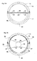
- Fig. 2a, 2b, 2c, 2d . 2e, 2f, 2g, 2h . 2i, and 2y show only a small number of examples of the numerous possible embodiments of one and / or more spacers, of which Fig. 2f, 2h and 2y a perspective view and bottom view of Fig. 2e, 2g and 2i demonstrate.
- Fig. 2a and Fig. 2c each show a spacer.
- This embodiment of the spacer has at least one clamping ring 12, which in any form, for example, a semicircle ( Fig. 2c ), Quarter arch, bow-shaped, C-shaped ( Fig. 2a ), Ellipse-shaped, semi-elliptical, in regular and irregular polygons, which is provided with at least one or more spacer ribs 13 with an outer investor ring 14, which in any shape, for example, a semicircle ( Fig. 2c ), Quarter-arch, arched, C-shaped ( Fig. 2a ), Ellipsoidal, semi-elliptical, may be executed in regular and irregular polygons and has a receiving opening 15 for mounting on the line to be protected or on the lines to be protected.
- Fig. 2b and 2d each show a spacer.
- This embodiment of the spacer has at least one clamping ring 12, which in any form, for example, a semicircle ( Fig. 2d ), Quarter arch, bow-shaped, C-shaped ( Fig. 2b ), Ellipse-shaped, semi-elliptical, may be executed in regular and irregular polygons, which is mounted with at least one or more spacer ribs 13 directly in the inside and / or in the protective jacket 11 (without investor ring 14) and has a receiving opening 15 for mounting.
- clamping ring 12 in any form, for example, a semicircle ( Fig. 2d ), Quarter arch, bow-shaped, C-shaped ( Fig. 2b ), Ellipse-shaped, semi-elliptical, may be executed in regular and irregular polygons, which is mounted with at least one or more spacer ribs 13 directly in the inside and / or in the protective jacket 11 (without investor ring 14) and has a receiving opening 15 for mounting.
- Fig. 2e and Fig. 2g show a further embodiment of a plurality of spacers 16, which consist of several arbitrarily shaped bodies, here for example in the form of Rectangles ( Fig. 2e ) and cylinders ( Fig. 2g ).
- the arbitrarily shaped bodies can be arranged on or in the inside of the protective jacket 11, vertically, horizontally or diagonally.
- the support surface or bearing surfaces 17 represent the line to be protected.
- the support surface or bearing surfaces 17 may be slightly arcuate in order to obtain an optimum adaptation to the line to be protected or to be protected lines, the support surface or the support surfaces, the line or lines to be protected must not touch.
- Fig. 2i shows a further embodiment, a spacer, extending in any body shape on the inside of the protective jacket 11, here for example in the form of a semi-ellipse 16. Wherein the running body forms the bearing surfaces 17 to be protected line or lines to be protected, but not must touch.
- Fig. 2f shows the bottom view of the Fig. 2e
- Fig. 2h shows the bottom view of the Fig. 2g
- Fig. 2j shows the bottom view of the Fig. 2i ,
- Fig. 3p shows a variant, the preferred embodiments of several spacers.
- Fig. 3p shows two spacers 16, each consisting of a square body on the inside of the protective jacket 11 extending.
- the line protection device In order to solve the existing problems of individual adaptation, the line protection device, to the numerous cable diameters of the line or lines to be protected, without manufacturing a specific line protection device specifically for the numerous line diameters and the respective specific properties, it is advantageous to have a device to create, which allows an individual adaptation to a variety of pipe diameters.
- the preferred embodiment of the line protection device includes one or more spacers and one or more devices for individual adaptation to the most varied tube diameters.
- the device is used for individual adaptation, if the outer diameter of the line or lines to be protected, not the inner diameter of the line protection device (protective sheath with spacer) corresponds.
- the required diameter is adjusted and / or by one or more built-in or factory pre-assembled or to be attached devices, by mounting the line protection device Volume of the line to be protected triggers a mechanism or this device is changed so that the Line protection device is fixed to the protected line or lines.
- the device for individual adaptation to a variety of diameters is not needed, ie this is not mounted or removed when this is detachably pre-assembled.
- the circuit protection device (protective sheath with spacer) is to be mounted alone, wherein the support surface of the spacer or spacers has direct contact with the line to be protected.
- the device for individual adaptation to a wide variety of diameters is not releasably attached, it is always used.
- the device for individual adaptation to a wide variety of diameters or the devices for individual adaptation to a wide variety of diameters characterized in that this individual adaptation and fixation of the line protection device or line protection devices to a variety of pipe diameters and their respective specific properties, to be protected Conduction or of lines allows.
- the device or devices for individual adaptation to a variety of diameters carried out in any way, arranged arbitrarily, placed anywhere on or in all elements of this line protection device or line protection devices and can be attached, and incorporated at the factory, factory pre-assembled or for assembly.
- a device or devices can be present or can, which allows a specific function. This device or devices for attachment can or can be performed in any way, arranged arbitrarily, placed anywhere in or on all elements of this line protection device or line protection devices and fixed, as well as factory incorporated, factory pre-assembled or can be included for mounting.
- a possible embodiment of a device or devices for individual adaptation to a wide variety of diameters may consist of several arbitrarily shaped body, which on or inside the protective jacket and / or on or in the spacer and / or on or in the spacers, again detachable , be placed in any order eg vertical, diagonal, horizontal.
- the attachment of the individual body can be done in any way.
- the inner diameter is individually reduced or increased, thus allowing an individual diameter adjustment.
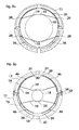
- FIG. 3a shows an example of such an embodiment of a device for individual adaptation to a variety of diameters in the assembled state, on a line to be protected 18 consisting of rectangular shaped bodies 19, preferably in an arcuate design of the support surface 24, to a better fit, at protective line or on the lines to get.
- a plug-in system Fig. 3b
- a sliding system Fig. 3c
- the spacer or protective sheath here, for example, diagonal, are attached.
- the inner diameter is reduced or increased, thus allowing a diameter adjustment, to the desired outer diameter of the line or lines to be protected.
- the support surface 24 represents.
- Another possible embodiment of a device or of devices for individual adaptation to a wide variety of diameters can be made from the use of one or more flexible or elastic materials and / or non-elastic materials which have been given elasticity by the shaping.
- the elastic material or the elastic property molding is respectively placed at the ends on or in the spacer and / or in or at the spacers and / or at or inside the protective jacket.
- the embodiment of a device for individual adaptation to the various diameters, which runs in the line protection device is pressed by the volume of the line or lines, in the direction of the protective jacket. Due to the resulting voltage, the line protection device is fixed to the line or lines to be protected.
- the attachment of this device on or in the protective jacket and / or on or in a spacer and / or on or in the spacers can be done in any way, as well as factory incorporated, factory pre-assembled or enclosed with the assembly.
- Fig. 3d, 3e, 3f, 3g and 3h show examples of such embodiments of a device or devices for individual adaptation to a variety of diameters.
- Fig. 3d shows two protective shell segments 11 attached together, with two spacers 16 which extend on the inside of each protective casing segment 11.
- the spring or the device for individual adaptation to a wide variety of diameters 19, can be additionally provided with a support surface, any shape, for example, here in the form of a rectangle 25, in a slight arcuate design. If no additional bearing surface is incorporated, represent the two springs, even the bearing surface, each with the surface that touches the line to be protected.
- the attachment of this device for individual adaptation to a variety of diameters may be on or in the protective jacket and / or on or in the spacer and / or on or in the spacers, on be made in any way, as well as factory-incorporated, factory pre-assembled or enclosed with the assembly.
- Fig. 3e, 3f and 3g show other shapes with elastic property.
- Fig. 3e shows a helical compression spring
- Fig. 3f shows a screw tension spring
- Fig. 3g shows a material in corrugated form.
- Fig. 3h shows an example of a usable elastic material, in the embodiment of a wide-shaped rubber.
- a device or devices for individual adaptation to different diameters may consist of several arbitrarily shaped bodies, which on one side, on or in a spacer and / or in or on the spacers and / or in or on the protective jacket , to be placed.
- the attachment can be made in any way, as well as factory incorporated, factory pre-assembled or included with the assembly.
- the other side of the body or arbitrarily shaped ends freely in the interior of the line protection device. Provided that in the installed state, the line protection device, the body, with the free-ending side or surface, with the line to be protected or the lines makes contact.
- the embodiment of a device for individual adaptation to a wide variety of diameters is pressed by the volume of the line or lines, in the direction of the protective jacket. Due to the resulting voltage, the line protection device is fixed to the line to be protected or to the lines.
- 3i, 3j, 3k and 3l show examples of such embodiments, a device or devices for individual adaptation to a variety of diameters, of which Fig. 3j and 3l show a detailed view.
- Fig. 3i shows a side view or detail view of two protective shell segments 11, with two spacers 16, mounted on a line 18 to be protected.
- the angled end is attached to or in the spacer and / or on or in the spacers 16 and / or on or in the protective sheath by plugging.
- the end with arcuate expression ends freely in the interior of the line protection device.
- No. 24 shows, the respective bearing surface, which is pressed in the assembled state, by the volume of the line to be protected, respectively in the direction 47 of the protective jacket and in the direction of the line protection device. Due to the resulting voltage, the entire line protection device is fixed to the line to be protected.
- Fig. 3j shows a detail view of the body, in the form of a rectangle, with a slightly curved pronounced end.
- Fig. 3k shows a side view and detailed view of two protective shell segments 11, with two spacers 16, in the assembled state, without to be protected line.
- the device for individual adaptation to a wide variety of diameters here consisting of two parallel mounted bending springs 19, which are each placed on one side of or in the spacer and / or on or in the spacers and / or on or in the protective jacket and in the assembled state free end in the interior of the line protection device.
- the two bending springs are pressed by the volume of the line to be protected or the lines, respectively in the direction 47 of the protective jacket and in the direction of the line protection device. Due to the resulting voltage, the entire line protection device is fixed to the line to be protected.
- the attachment of the device for individual adaptation to a variety of diameters, of which any number can be used, can be done in any way, as well as factory incorporated, factory pre-assembled or enclosed with the assembly.
- Fig. 3l shows a detail view of a bending spring.
- a device or devices for individual adaptation to a variety of diameters may consist of several arbitrarily shaped and flexible bodies, each on one side of or in the spacer and / or on or in the spacers and / or on or in Protective jacket, can be fixed in any way, as well as pre-assembled at the factory, factory-incorporated or supplied for assembly.
- four arbitrarily shaped bodies represent a unit, a device for individual adaptation to a wide variety of diameters and any number of these units can be used.
- two arbitrarily shaped and flexible bodies may be provided by means of one or more connecting devices in order to grip around the other body and / or to provide any arbitrarily shaped and flexible body with one or more connecting devices.
- Fig. 3m shows an example of such an embodiment of an apparatus for individual adaptation to a variety of diameters.
- Fig. 3m shows a side view of two protective shell segments 11, with two spacers 16, in the assembled state, with no line to be protected.
- a device or devices for individual adaptation to a variety of diameters may consist of several flexible or elastic materials, in any body shape.
- the arbitrarily shaped bodies are in each case at the ends on or in the spacer and / or on or in the spacers and / or on or in the inside of the protective jacket and / or by means of a special device or devices located in or on the spacer and / or in or on the spacers and / or on or in the protective jacket, so fastened or attached, that in the mounted state, the flexible or elastic body touches the line to be protected or the lines.
- the embodiment of a device or the devices for individual adaptation to the various diameters which runs in the line protection device, pressed by the volume of the conduit, in the direction of the protective jacket, wherein the ends of the or the arbitrarily shaped body, the Retain position and / or change position. Due to the resulting voltage, the line protection device is fixed to the line to be protected.
- the attachment of this device or the devices for individual adaptation to a variety of diameters can be done in any way, as well as include a special or additional device or fixtures for attachment, which allows a specific function. From this device for individual adaptation to a wide variety of diameters, can be used as many as desired, as well as incorporated at the factory, factory pre-assembled or enclosed with the assembly.
- Fig. 3n . 3o and Fig. 3p show examples of such preferred embodiments of a device or devices for individual adaptation to a variety of diameters.
- Fig. 3n shows a side view of two protective casing segments 11, with two spacers 16, each consisting of a square body, here on the inside, the respective protective casing segment 11 extending, in the assembled state, on a line to be protected 18.
- This device for stationary attachment for example, by means of a receiving device 27, which allows the introduction and attachment of the device for individual adaptation to different diameters, without shortening or mobility of the ends of the flexible bodies required and / or by means of insertion holes ( Fig. 3o No. 28), which requires at one end or the ends of the flexible bodies a mobility, at least one end, which allows a time-wise shortening of one or more ends to allow the fastening or insertion into the insertion holes and the decrease. Furthermore, it would be possible to attach the device for individual adaptation to a variety of diameters by means of hoes, eyes or the like, so that the ends can be fixed stationary.
- the embodiment of a device for individual adaptation to the various diameters 19, which runs in the line protection device is pressed by the volume of the line 18, in the direction of the protective jacket. Whereby the ends of the or the arbitrarily shaped body, maintain the position. Due to the resulting voltage, the line protection device is fixed to the line to be protected.
- this embodiment of a device for individual adaptation to a wide variety of diameters can be used, as well as incorporated at the factory, pre-assembled at the factory or supplied for assembly.
- Fig. 3p shows a side view of two protective shell segments 11, with two spacers 16, each consisting of a square body, run on the inside, the protective jacket 11, in the mounted state, on a line to be protected 18.
- the device for individual adaptation to the different diameters 19th In this embodiment, each consists of two flexible body, in a slight w-like training and arbitrary shaping of the ends, here in T-shaped design.
- one or more guide rails 29 are attached to fix the device for individual adaptation to the most varied diameters 19, which are placed arbitrarily on or in the spacer and / or on or in the spacers and / or on or in the inside of the protective jacket and can run continuously and / or in sections .
- the flexible body When using a continuous guide rail, the flexible body is inserted at the respective open ends of the guide rail. Are the guide rails only partially extending, the resulting space 31 can be used in addition to the assembly 30 of the flexible body by each compressed the ends of the flexible body, and positioned in the free space 30 and inserted into guide rails 29.
- the embodiment of a device for individual adaptation to the various diameters 19, which runs in the line protection device is pressed by the volume of the line 18 and the lines, in the direction of the protective jacket. Wherein the ends of the arbitrarily shaped body 19, the position in the guide rail or guide notes change and run in opposite directions. Due to the resulting voltage, the line protection device is fixed to the line to be protected. From this embodiment of a device for individual adaptation to a wide variety of diameters can be used as many, as well as factory pre-assembled or enclosed with the assembly.
- each type of closure whether incorporated at the factory, factory pre-assembled or for external attachment, is suitable.
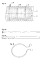
- Fig. 4a and 4b show examples of factory-incorporated closure options.
- Fig. 4d, 4e and 4f show examples of external closure options.
- Fig. 4c show the Figures 4d, 4e and 4f in the applied state.
- Fig. 4a shows an example of a preferred embodiment of a closure option, if there are a plurality of spacers consisting of a plurality of closure members and mating closure members, which are preferably incorporated directly into or on the spacers and / or attached as an extension to the spacers.
- the respective closure member 32 has a latching nose 34 which is inserted into the counter-locking member 33 designed as a locking cage. To the closure member 32 and counter-locking member 33, to solve again, pressure is exerted on the locking lugs 34.
- Fig. 4b shows a further embodiment of a closure possibility, consisting of a plurality of closure members and mating closure members, which are arbitrarily positioned and mounted on the outside of the line protection device.
- the closure member 32 has a latching nose 34 which is inserted into the counter-locking member 33 designed as a locking cage.
- the closure members and counter-locking members can be arbitrarily positioned on the protective jacket and fixed in any manner, for example by means of a connection which allows pivoting.
- Fig. 4c shows examples of externally mounted closure options on two protective shell segments 11.
- No. 35 shows a possible closure variant by means of cable trimmers
- No. 36 shows a possible closure variant by means of cable ties
- No. 37 by means of Velcro strips.
- Fig. 4f shows a detail view of a cable cutter, corresponding to No. 35.
- Fig. 4d shows a detail view of a cable tie, corresponding to No. 36.
- Fig. 4e shows a detailed view of a Velcro tape, corresponding to No. 37.
- the protective jacket and / or the protective shells and / or protective sheath segments and the selected closure variant or their placement it may be advantageous to provide the protective sheath and / or the protective shells and / or the protective sheath segments, with a device which a lateral prevents slipping.
- This device which prevents slipping sideways, can be carried out in any way and find any number of uses and is characterized in that it prevents or prevent lateral slippage or opening up of the line protection device.
- Fig. 5a and 5b show examples of such a device, which prevents lateral slippage.
- Fig. 5a shows a detailed views of two protective sheath segments 11. Where a protective sheath segment on the longitudinal edge one or more extensions in the form of a pin or stabilizing pin 38 and the other protective sheath segment at the opposite position or points has a counter recess 39 or have. When the protective sheath segments are closed, the stabilizing pin or pins 38 are inserted into the opposing counterbore or counterbores 39.
- Fig. 5b shows a detailed views of two protective casing segments 11.
- a protective casing segment along the longitudinal edge, on the outside and / or inside of the protective casing segment has one or more stabilizing pins 38, in any length and shape or have. After mounting the line protection device, this stabilizing pin 38 or these stabilizing pins prevents lateral slippage and brings during assembly the advantage that no precise insertion into a counter-recess or counter-recesses is required.
- One of the other possibilities would be to attach a plurality of stabilizing pins to the respective longitudinal edges of a protective sheath and / or protective sheaths and / or protective sheath segments.
- Fig. 5c shows two interconnected protective sheath segments 11, wherein a protective shroud segment is here provided with an externally mounted stabilizing pin 38, in the middle of the line protector length.
- the protective sheaths and / or the protective sheath segments it is advantageous to provide a device which allows a juxtaposition or joining adjacent, immediately adjacent protective shells and / or protective sheath segments, which can be performed in any way.
- Fig. 6a, 6b, 6c and 6d show examples of possible embodiments of such a device for juxtaposing or connecting adjacent, immediately adjacent protective sheaths and / or protective sheath segments.
- Fig. 6a and Fig. 6b shows an example of a detailed view of two interconnected protective sheath segments 11, which have on the front side of the protective sheath segments, a device for connecting adjacent, immediately adjacent protective shells and / or protective sheath segments.
- Fig. 6a shows two interconnected protective sheath segments 11, which at one end face with Any number of lugs 40 are provided.
- Fig. 6b shows two interconnected protective sheath segments 11, which are provided on an end face with any number of counter-recesses, the nose mold 41.
- Fig. 6a and 6b are connected by merging the lugs 40 and the respective counter-recess in nose-shaped 41 with each other.
- Fig. 6c and Fig. 6d shows an example of a detailed view of two interconnected protective sheath segments 11, which have on the front side of the protective sheath segments, a device for connecting adjacent, immediately adjacent protective shells or protective sheath segments.
- Fig. 6c has a plurality of closure members, each with a latching lug 42.
- Fig. 6d has a plurality of counter-locking members 43 in the form of a cage, for latching the locking lug on.
- the closure members with locking lug 42 and the counter-locking members 43 can be arbitrarily placed and fixed in any way, and be pivotally fixed eg by means of pin connections 44 or fixed.
- the line protection device which are characterized in that the special finishing protective sheaths and / or the final protection sheath segments, in any length and diameter configuration, in any body shape, e.g. semicircle, quarter-arch, arcuate, C-shaped, elliptical, semi-elliptical, non-circular, in regular and irregular polygons, the end caps and / or the end shields segments being of any type e.g. accordion-shaped, corrugated, smooth, cross-ribbed, trapezoidal, rectangular, and these formations may run in any arrangement, e.g. vertical, horizontal, diagonal.
- the special finishing protective sheaths and / or the final protection sheath segments in any length and diameter configuration, in any body shape, e.g. semicircle, quarter-arch, arcuate, C-shaped, elliptical, semi-elliptical, non-circular, in regular and irregular polygons
- the end caps and / or the end shields segments being of any type e.
- the design, the arrangement, the length and diameter can be performed. But no spacer or spacers and / or no device or devices for individual adaptation to a wide variety of pipe diameters must be included.
- any type of attachment is possible, which allows a juxtaposition or a connection.
- this attachment which allows a juxtaposition or a connection, it may be necessary, in order to prevent sufficient stability or solving to provide these calendarterrorismmäntel and / or the considered legion labor costsegmente with a device which connect to each other or close allows.
- Fig. 7a, 7b, 7c and 7d show examples of possible embodiments of a plurality of end protective sheath segments and examples of mounting options for lining up adjacent, immediately adjacent protective sheath or adjacent protective sheath segments and examples of a device of the lock together.
- Fig. 7a shows two end protective sheath segments 45, in combination of concertina-like and smooth training, in the body shape of a semicircle.
- the two end protective sheath segments 45 of Fig. 7a show two examples of a device of closing together, at the longitudinal edge of the end protection shell segments.
- No. 32 shows a closure member with locking lug 34, which connects or closes by inserting into the counter-closure member 33, the two end protection shell segments.
- No. 40 shows a nose which, by insertion into the counter recess 41, connects or closes off two end protective sheath segments.
- Fig. 7b shows two relievetikmantelsegmente 45, in accordion-like design and horizontal, slightly diagonal arrangement, in the form of a semi-circle, which has a diameter reduction on one end face.
- This concertina-shaped design, in a horizontal, slightly diagonal arrangement, allows additional flexibility to reduce the diameter.
- On the other end face is a device which allows the juxtaposition, adjacent adjacent protective sheath or adjacent protective sheath segments, here in the form of lugs 40.
- Fig. 7c shows a closure protective sheath segment 45, in a smooth design, in the form of a semi-circle, which has on one end a diameter reduction and on the other end a device which the juxtaposing, on adjacent immediately adjacent protective sheath or of adjacent protective sheath segments, here in the form of Noses, in angular shape 40.
- Fig. 7d shows a cover shell segment 45, in accordion-like design and vertical arrangement or vertically extending, in the form of a semi-circle, which has a diameter reduction on one end face.
- the concertina-shaped training in a vertical arrangement an additional flexibility for length adjustment is possible.
- At the other end side there is a device, which allows the juxtaposition, on adjacent directly adjacent protective sheath or of adjacent protective sheath segments, here in the form of lugs, in cube-like form 40th
- Fig. 8 shows an example of such an embodiment, a device with hinge-like property, on two semi-circular body shapes 11, which are connected to each other by means of an embossment 48, here of the same material, with each other.
- the line protection device or line protection devices with their numerous variations and elements can be additionally provided with ventilation slots or ventilation chambers and / or perforations, any shape, any size and arrangement.
- Fig. 3p shows an example of incorporated ventilation slots 46.
- line protection devices or line protection devices can be made of any suitable material or material and material combinations, as well as in any color, nuance and color combinations.
Landscapes
- Engineering & Computer Science (AREA)
- Architecture (AREA)
- Civil Engineering (AREA)
- Structural Engineering (AREA)
- General Engineering & Computer Science (AREA)
- Mechanical Engineering (AREA)
- Details Of Indoor Wiring (AREA)
- Flexible Shafts (AREA)
- Suspension Of Electric Lines Or Cables (AREA)
- Catching Or Destruction (AREA)
- Train Traffic Observation, Control, And Security (AREA)
Claims (6)
- Dispositif de protection des circuits pour la protection d'au moins un circuit(18), de toutes sortes, en particulier pour la protection des circuits des véhicules et des espaces de vie quotidiens, contre les morsures d'animaux et/ou généralement pour l'assemblage et/ou l'enveloppement d'où au moins un circuit(18), sachant que le dispositif de protection des circuits comporte au moins une gaine de protection (11) et/ou un segment de gaine de protection, qui puisse(ent) être réalisé(s) à une longueur et à un diamètre quelconques ainsi qu'à partir de formes différentes, sachant qu'au moins une entretoise et/ou au moins un dispositif d'adaptation individuel à différents diamètres est prévu et sachant que le cas échéant est prévu en outre au moins un dispositif supplémentaire, lequel empêche la gaine de glisser latéralement ou de s'écarter, caractérisé en ce quea) Le dispositif se compose d'au moins deux ressorts (19) pour s'adapter individuellement à différents diamètresb) Et que le dispositif supplémentaire comporte deux rails parallèles (26) lesquelles parcourent à l'intérieur ou sur la face intérieure du dispositif de protection des circuits.
- Le dispositif de protection des circuits selon la revendication 1, est caractérisé en ce que les deux rails parallèles (26) sont équipés de trous d'insertion.
- Le dispositif de protection des circuits selon les revendications 1 ou 2 est caractérisé en ce que les ressorts (19) sont constitués comme deux vis-ressorts de traction et/ou au moins comme deux caoutchoucs lesquels sont placés parallèlement l'un par rapport à l'autre et chacune des deux extrémités pouvant être attachés sur les côtés opposés à l'intérieur ou sur la face intérieure du dispositif de protection des circuits.
- Le dispositif de protection des circuits selon la revendication 3 est caractérisé en ce que les ressorts (19) puissent être équipés d'une surface d'appui supplémentaire, de préférence de forme légèrement curviligne.
- Le dispositif de protection des circuits selon la revendication 3 est caractérisé en ce que les ressorts (19) sont formés comme au moins deux ressorts courbes, lesquels sont placés en miroirs et inversés latéralement et pouvant être attachés chacun sur un côté, de différentes manières, à l'intérieur ou sur la face intérieure du dispositif de protection des circuits et l'autre extrémité se terminant librement à l'intérieur du dispositif de protection des circuits.
- Le dispositif de protection des circuits selon la revendication 3 est caractérisé en ce que les ressorts sont formés comme deux corps flexibles, en forme de w, avec deux extrémités de forme quelconque, de préférence en forme de T, lesquels sont placées en miroir et les deux extrémités s'attachant de manière mobile ou fixe sur la face intérieure ou à l'intérieur du dispositif de protection des circuits.
Applications Claiming Priority (2)
| Application Number | Priority Date | Filing Date | Title |
|---|---|---|---|
| DE102004018313A DE102004018313A1 (de) | 2004-04-13 | 2004-04-13 | Leitungsschutzvorrichtung |
| DE102004018313 | 2004-04-13 |
Publications (3)
| Publication Number | Publication Date |
|---|---|
| EP1587193A2 EP1587193A2 (fr) | 2005-10-19 |
| EP1587193A3 EP1587193A3 (fr) | 2006-08-02 |
| EP1587193B1 true EP1587193B1 (fr) | 2010-06-16 |
Family
ID=34585430
Family Applications (1)
| Application Number | Title | Priority Date | Filing Date |
|---|---|---|---|
| EP05005776A Expired - Lifetime EP1587193B1 (fr) | 2004-04-13 | 2005-03-16 | Dispositif protecteur de câble |
Country Status (3)
| Country | Link |
|---|---|
| EP (1) | EP1587193B1 (fr) |
| AT (1) | ATE471587T1 (fr) |
| DE (2) | DE102004018313A1 (fr) |
Cited By (2)
| Publication number | Priority date | Publication date | Assignee | Title |
|---|---|---|---|---|
| DE102020005082B3 (de) | 2020-09-02 | 2021-10-14 | G-quadrat Geokunststoffgesellschaft mbH | Flexible Textilstruktur, Bodenbauelement mit einer flexiblen Textilstruktur, Verfahren zur Herstellung eines Bodenbauelements, Erdleitungs-Schutzsystem und Verfahren zur Herstellung eines Erdleitungs-Schutzsystems sowie Verwendung des Bodenbauelements |
| EP4112967A1 (fr) * | 2021-06-28 | 2023-01-04 | Nexans | Amortisseur de vibrations |
Families Citing this family (4)
| Publication number | Priority date | Publication date | Assignee | Title |
|---|---|---|---|---|
| ES2258934B1 (es) * | 2005-12-09 | 2007-06-16 | Tom Hutchinson | Elemento de proteccion local de cables. |
| JP5638939B2 (ja) * | 2010-12-28 | 2014-12-10 | 矢崎総業株式会社 | ワイヤハーネス及びワイヤハーネスの製造方法 |
| CN111963915B (zh) * | 2020-08-13 | 2025-01-03 | 安徽信息工程学院 | 一种手电筒结构 |
| CN119400488B (zh) * | 2024-11-06 | 2025-08-05 | 东莞顺辉电业制品有限公司 | 一种复合绞线增强芯电缆及其制备方法 |
Family Cites Families (11)
| Publication number | Priority date | Publication date | Assignee | Title |
|---|---|---|---|---|
| FR1344705A (fr) * | 1963-01-16 | 1963-11-29 | Atlas Copco Ab | Dispositif de montage et de soutien pour câbles électriques |
| DE1881159U (de) * | 1963-07-18 | 1963-10-24 | E Vogelsang Fa Dipl Ing Dr | Kabelschutzrohr. |
| GB2009523B (en) * | 1977-09-13 | 1982-07-07 | Owen W J | Trunking systems for conduits or cables |
| FR2591306B1 (fr) * | 1985-12-09 | 1988-07-22 | Bourreau Bruno | Procede pour la realisation d'un reseau fixe de transport de fluide dans un batiment, dispositif de guidage et de maintien pour la realisation d'un tel reseau, et reseau obtenu par ce procede |
| DE19751611A1 (de) * | 1996-06-05 | 1999-05-27 | Georg Krain | Folien ummantelte Installationskanäle und Lichtblenden |
| US5800762A (en) * | 1996-12-06 | 1998-09-01 | Bethel; Eunice A. | Process for decorating electrical cords |
| GB9713598D0 (en) * | 1997-06-28 | 1997-09-03 | T & N Technology Ltd | Flexible protective sleeve |
| DE10031692A1 (de) * | 2000-06-29 | 2002-01-10 | Alsta Aluminium Und Stahl Gmbh | Stecksystem |
| GB2365941A (en) * | 2000-08-16 | 2002-02-27 | Balmoral Group | Protective sleeving |
| WO2002054553A2 (fr) * | 2001-01-02 | 2002-07-11 | Barry Howard | Installation de cable et composants associes |
| DE10139740C1 (de) * | 2001-08-13 | 2003-04-17 | Schlemmer Gmbh | Rohrverbindungsteil für Wellrohre mit innenliegendem Dämpfungselement |
-
2004
- 2004-04-13 DE DE102004018313A patent/DE102004018313A1/de not_active Withdrawn
-
2005
- 2005-03-16 DE DE502005009742T patent/DE502005009742D1/de not_active Expired - Lifetime
- 2005-03-16 AT AT05005776T patent/ATE471587T1/de active
- 2005-03-16 EP EP05005776A patent/EP1587193B1/fr not_active Expired - Lifetime
Cited By (2)
| Publication number | Priority date | Publication date | Assignee | Title |
|---|---|---|---|---|
| DE102020005082B3 (de) | 2020-09-02 | 2021-10-14 | G-quadrat Geokunststoffgesellschaft mbH | Flexible Textilstruktur, Bodenbauelement mit einer flexiblen Textilstruktur, Verfahren zur Herstellung eines Bodenbauelements, Erdleitungs-Schutzsystem und Verfahren zur Herstellung eines Erdleitungs-Schutzsystems sowie Verwendung des Bodenbauelements |
| EP4112967A1 (fr) * | 2021-06-28 | 2023-01-04 | Nexans | Amortisseur de vibrations |
Also Published As
| Publication number | Publication date |
|---|---|
| DE502005009742D1 (de) | 2010-07-29 |
| DE102004018313A1 (de) | 2005-06-16 |
| ATE471587T1 (de) | 2010-07-15 |
| EP1587193A3 (fr) | 2006-08-02 |
| EP1587193A2 (fr) | 2005-10-19 |
Similar Documents
| Publication | Publication Date | Title |
|---|---|---|
| DE60019475T2 (de) | Kabelbaumschaumschutz der über die Kabel einrastet | |
| DE102018217839B4 (de) | Kabelbaumschutzeinrichtung und Herstellungsverfahren für den Kabelbaum | |
| EP0268869B1 (fr) | Dispositif à tuyau protecteur en matériau synthétique pour conduites | |
| DE112013003678B4 (de) | Draht-Schutzelement | |
| EP2832943A1 (fr) | Penture recouverte dotée de liaison électrique | |
| DE10050565A1 (de) | Kabelbaum-Abwinkelvorrichtung | |
| DE112019002841T5 (de) | Kabelbaum | |
| EP1587193B1 (fr) | Dispositif protecteur de câble | |
| EP3488498A1 (fr) | Ensemble formant cadre de support muni d'un cadre de base et d'un élément de fixation et procédé d'assemblage | |
| DE112013004193T5 (de) | Führungsstruktur für elektrische Leitungen | |
| DE102009030798A1 (de) | Schutzvorrichtung für flexible Elemente | |
| EP0535712B1 (fr) | Faisceau de câble ou puits à câbles, particulièrement pour une voiture automobile | |
| DD265449A1 (de) | Kabel- und schlauchschlepp | |
| DE102016112758A1 (de) | Halteteil und verfahren zum befestigen von elektrischen leitungen sowie leitungsanordnng in einem fahrzeug | |
| DE202014101359U1 (de) | Endbefestigungsteil für Leitungsführungseinrichtung | |
| EP1119087B1 (fr) | Boíte d'encastrement pour canalisations de câbles | |
| DE102014109270B4 (de) | Leitungsfixierung, Stecker mit einer Leitungsfixierung und Verfahren zum Fixieren einer elektrischen Leitung an einem Stecker | |
| EP0709252B1 (fr) | Faisceau de câbles en particulier pour le montage dans une carosserie de voiture | |
| DE202004013160U1 (de) | Hochstromschnittstelle für Kraftfahrzeuge | |
| DE102014004931A1 (de) | Abstandshalteeinrichtung | |
| DE102004005310B4 (de) | Geschlitztes Rohr, insbesondere Wellrohr zur schützenden Ummantelung von elektrischen Kabeln in Kraftfahrzeugen, sowie ein das Rohr verschließendes Verschlußmittel | |
| DE102020208965A1 (de) | Ladeleitung für ein Elektrofahrzeug | |
| DE19943763C5 (de) | Schutzumhüllung für eine elektrische Leitung | |
| DE102012020105A1 (de) | Kabelführungseinrichtung zur Verwendung bei der Installation von Kabeln | |
| DE102018109476A1 (de) | Kabelhalter |
Legal Events
| Date | Code | Title | Description |
|---|---|---|---|
| PUAI | Public reference made under article 153(3) epc to a published international application that has entered the european phase |
Free format text: ORIGINAL CODE: 0009012 |
|
| AK | Designated contracting states |
Kind code of ref document: A2 Designated state(s): AT BE BG CH CY CZ DE DK EE ES FI FR GB GR HU IE IS IT LI LT LU MC NL PL PT RO SE SI SK TR |
|
| AX | Request for extension of the european patent |
Extension state: AL BA HR LV MK YU |
|
| PUAL | Search report despatched |
Free format text: ORIGINAL CODE: 0009013 |
|
| AK | Designated contracting states |
Kind code of ref document: A3 Designated state(s): AT BE BG CH CY CZ DE DK EE ES FI FR GB GR HU IE IS IT LI LT LU MC NL PL PT RO SE SI SK TR |
|
| AX | Request for extension of the european patent |
Extension state: AL BA HR LV MK YU |
|
| 17P | Request for examination filed |
Effective date: 20070202 |
|
| AKX | Designation fees paid |
Designated state(s): AT BE BG CH CY CZ DE DK EE ES FI FR GB GR HU IE IS IT LI LT LU MC NL PL PT RO SE SI SK TR |
|
| GRAP | Despatch of communication of intention to grant a patent |
Free format text: ORIGINAL CODE: EPIDOSNIGR1 |
|
| GRAS | Grant fee paid |
Free format text: ORIGINAL CODE: EPIDOSNIGR3 |
|
| GRAA | (expected) grant |
Free format text: ORIGINAL CODE: 0009210 |
|
| AK | Designated contracting states |
Kind code of ref document: B1 Designated state(s): AT BE BG CH CY CZ DE DK EE ES FI FR GB GR HU IE IS IT LI LT LU MC NL PL PT RO SE SI SK TR |
|
| REG | Reference to a national code |
Ref country code: CH Ref legal event code: EP |
|
| REG | Reference to a national code |
Ref country code: IE Ref legal event code: FG4D Free format text: LANGUAGE OF EP DOCUMENT: GERMAN |
|
| REF | Corresponds to: |
Ref document number: 502005009742 Country of ref document: DE Date of ref document: 20100729 Kind code of ref document: P |
|
| REG | Reference to a national code |
Ref country code: NL Ref legal event code: VDEP Effective date: 20100616 |
|
| PG25 | Lapsed in a contracting state [announced via postgrant information from national office to epo] |
Ref country code: SE Free format text: LAPSE BECAUSE OF FAILURE TO SUBMIT A TRANSLATION OF THE DESCRIPTION OR TO PAY THE FEE WITHIN THE PRESCRIBED TIME-LIMIT Effective date: 20100616 Ref country code: LT Free format text: LAPSE BECAUSE OF FAILURE TO SUBMIT A TRANSLATION OF THE DESCRIPTION OR TO PAY THE FEE WITHIN THE PRESCRIBED TIME-LIMIT Effective date: 20100616 |
|
| LTIE | Lt: invalidation of european patent or patent extension |
Effective date: 20100616 |
|
| PG25 | Lapsed in a contracting state [announced via postgrant information from national office to epo] |
Ref country code: FI Free format text: LAPSE BECAUSE OF FAILURE TO SUBMIT A TRANSLATION OF THE DESCRIPTION OR TO PAY THE FEE WITHIN THE PRESCRIBED TIME-LIMIT Effective date: 20100616 Ref country code: SI Free format text: LAPSE BECAUSE OF FAILURE TO SUBMIT A TRANSLATION OF THE DESCRIPTION OR TO PAY THE FEE WITHIN THE PRESCRIBED TIME-LIMIT Effective date: 20100616 |
|
| PG25 | Lapsed in a contracting state [announced via postgrant information from national office to epo] |
Ref country code: CY Free format text: LAPSE BECAUSE OF FAILURE TO SUBMIT A TRANSLATION OF THE DESCRIPTION OR TO PAY THE FEE WITHIN THE PRESCRIBED TIME-LIMIT Effective date: 20100616 Ref country code: PL Free format text: LAPSE BECAUSE OF FAILURE TO SUBMIT A TRANSLATION OF THE DESCRIPTION OR TO PAY THE FEE WITHIN THE PRESCRIBED TIME-LIMIT Effective date: 20100616 Ref country code: GR Free format text: LAPSE BECAUSE OF FAILURE TO SUBMIT A TRANSLATION OF THE DESCRIPTION OR TO PAY THE FEE WITHIN THE PRESCRIBED TIME-LIMIT Effective date: 20100917 |
|
| REG | Reference to a national code |
Ref country code: IE Ref legal event code: FD4D |
|
| PG25 | Lapsed in a contracting state [announced via postgrant information from national office to epo] |
Ref country code: IE Free format text: LAPSE BECAUSE OF FAILURE TO SUBMIT A TRANSLATION OF THE DESCRIPTION OR TO PAY THE FEE WITHIN THE PRESCRIBED TIME-LIMIT Effective date: 20100616 Ref country code: NL Free format text: LAPSE BECAUSE OF FAILURE TO SUBMIT A TRANSLATION OF THE DESCRIPTION OR TO PAY THE FEE WITHIN THE PRESCRIBED TIME-LIMIT Effective date: 20100616 Ref country code: EE Free format text: LAPSE BECAUSE OF FAILURE TO SUBMIT A TRANSLATION OF THE DESCRIPTION OR TO PAY THE FEE WITHIN THE PRESCRIBED TIME-LIMIT Effective date: 20100616 |
|
| PG25 | Lapsed in a contracting state [announced via postgrant information from national office to epo] |
Ref country code: RO Free format text: LAPSE BECAUSE OF FAILURE TO SUBMIT A TRANSLATION OF THE DESCRIPTION OR TO PAY THE FEE WITHIN THE PRESCRIBED TIME-LIMIT Effective date: 20100616 Ref country code: SK Free format text: LAPSE BECAUSE OF FAILURE TO SUBMIT A TRANSLATION OF THE DESCRIPTION OR TO PAY THE FEE WITHIN THE PRESCRIBED TIME-LIMIT Effective date: 20100616 Ref country code: CZ Free format text: LAPSE BECAUSE OF FAILURE TO SUBMIT A TRANSLATION OF THE DESCRIPTION OR TO PAY THE FEE WITHIN THE PRESCRIBED TIME-LIMIT Effective date: 20100616 Ref country code: IS Free format text: LAPSE BECAUSE OF FAILURE TO SUBMIT A TRANSLATION OF THE DESCRIPTION OR TO PAY THE FEE WITHIN THE PRESCRIBED TIME-LIMIT Effective date: 20101016 Ref country code: PT Free format text: LAPSE BECAUSE OF FAILURE TO SUBMIT A TRANSLATION OF THE DESCRIPTION OR TO PAY THE FEE WITHIN THE PRESCRIBED TIME-LIMIT Effective date: 20101018 |
|
| PG25 | Lapsed in a contracting state [announced via postgrant information from national office to epo] |
Ref country code: IT Free format text: LAPSE BECAUSE OF FAILURE TO SUBMIT A TRANSLATION OF THE DESCRIPTION OR TO PAY THE FEE WITHIN THE PRESCRIBED TIME-LIMIT Effective date: 20100616 |
|
| PLBE | No opposition filed within time limit |
Free format text: ORIGINAL CODE: 0009261 |
|
| STAA | Information on the status of an ep patent application or granted ep patent |
Free format text: STATUS: NO OPPOSITION FILED WITHIN TIME LIMIT |
|
| PG25 | Lapsed in a contracting state [announced via postgrant information from national office to epo] |
Ref country code: DK Free format text: LAPSE BECAUSE OF FAILURE TO SUBMIT A TRANSLATION OF THE DESCRIPTION OR TO PAY THE FEE WITHIN THE PRESCRIBED TIME-LIMIT Effective date: 20100616 |
|
| 26N | No opposition filed |
Effective date: 20110317 |
|
| REG | Reference to a national code |
Ref country code: DE Ref legal event code: R097 Ref document number: 502005009742 Country of ref document: DE Effective date: 20110316 |
|
| BERE | Be: lapsed |
Owner name: KRAMER, KARL Effective date: 20110331 Owner name: MAKOHONENKO, MASCHA ALEXANDRA Effective date: 20110331 |
|
| PG25 | Lapsed in a contracting state [announced via postgrant information from national office to epo] |
Ref country code: MC Free format text: LAPSE BECAUSE OF NON-PAYMENT OF DUE FEES Effective date: 20110331 |
|
| REG | Reference to a national code |
Ref country code: CH Ref legal event code: PL |
|
| GBPC | Gb: european patent ceased through non-payment of renewal fee |
Effective date: 20110316 |
|
| REG | Reference to a national code |
Ref country code: FR Ref legal event code: ST Effective date: 20111130 |
|
| PG25 | Lapsed in a contracting state [announced via postgrant information from national office to epo] |
Ref country code: BE Free format text: LAPSE BECAUSE OF NON-PAYMENT OF DUE FEES Effective date: 20110331 |
|
| PG25 | Lapsed in a contracting state [announced via postgrant information from national office to epo] |
Ref country code: CH Free format text: LAPSE BECAUSE OF NON-PAYMENT OF DUE FEES Effective date: 20110331 Ref country code: DE Free format text: LAPSE BECAUSE OF NON-PAYMENT OF DUE FEES Effective date: 20111001 Ref country code: LI Free format text: LAPSE BECAUSE OF NON-PAYMENT OF DUE FEES Effective date: 20110331 Ref country code: FR Free format text: LAPSE BECAUSE OF NON-PAYMENT OF DUE FEES Effective date: 20110331 |
|
| REG | Reference to a national code |
Ref country code: DE Ref legal event code: R119 Ref document number: 502005009742 Country of ref document: DE Effective date: 20111001 |
|
| PG25 | Lapsed in a contracting state [announced via postgrant information from national office to epo] |
Ref country code: GB Free format text: LAPSE BECAUSE OF NON-PAYMENT OF DUE FEES Effective date: 20110316 |
|
| REG | Reference to a national code |
Ref country code: AT Ref legal event code: MM01 Ref document number: 471587 Country of ref document: AT Kind code of ref document: T Effective date: 20110316 |
|
| PG25 | Lapsed in a contracting state [announced via postgrant information from national office to epo] |
Ref country code: AT Free format text: LAPSE BECAUSE OF NON-PAYMENT OF DUE FEES Effective date: 20110316 |
|
| PG25 | Lapsed in a contracting state [announced via postgrant information from national office to epo] |
Ref country code: LU Free format text: LAPSE BECAUSE OF NON-PAYMENT OF DUE FEES Effective date: 20110316 |
|
| PG25 | Lapsed in a contracting state [announced via postgrant information from national office to epo] |
Ref country code: TR Free format text: LAPSE BECAUSE OF FAILURE TO SUBMIT A TRANSLATION OF THE DESCRIPTION OR TO PAY THE FEE WITHIN THE PRESCRIBED TIME-LIMIT Effective date: 20100616 Ref country code: BG Free format text: LAPSE BECAUSE OF FAILURE TO SUBMIT A TRANSLATION OF THE DESCRIPTION OR TO PAY THE FEE WITHIN THE PRESCRIBED TIME-LIMIT Effective date: 20100916 |
|
| PG25 | Lapsed in a contracting state [announced via postgrant information from national office to epo] |
Ref country code: ES Free format text: LAPSE BECAUSE OF FAILURE TO SUBMIT A TRANSLATION OF THE DESCRIPTION OR TO PAY THE FEE WITHIN THE PRESCRIBED TIME-LIMIT Effective date: 20100927 Ref country code: HU Free format text: LAPSE BECAUSE OF FAILURE TO SUBMIT A TRANSLATION OF THE DESCRIPTION OR TO PAY THE FEE WITHIN THE PRESCRIBED TIME-LIMIT Effective date: 20100616 |