EP1587193B1 - Wire protection device - Google Patents
Wire protection device Download PDFInfo
- Publication number
- EP1587193B1 EP1587193B1 EP05005776A EP05005776A EP1587193B1 EP 1587193 B1 EP1587193 B1 EP 1587193B1 EP 05005776 A EP05005776 A EP 05005776A EP 05005776 A EP05005776 A EP 05005776A EP 1587193 B1 EP1587193 B1 EP 1587193B1
- Authority
- EP
- European Patent Office
- Prior art keywords
- protection device
- line
- line protection
- protective
- springs
- Prior art date
- Legal status (The legal status is an assumption and is not a legal conclusion. Google has not performed a legal analysis and makes no representation as to the accuracy of the status listed.)
- Expired - Lifetime
Links
- 230000004224 protection Effects 0.000 title claims abstract description 81
- 230000001681 protective effect Effects 0.000 claims abstract description 151
- 125000006850 spacer group Chemical group 0.000 claims description 39
- 230000009975 flexible effect Effects 0.000 claims description 18
- 238000003780 insertion Methods 0.000 claims description 7
- 230000037431 insertion Effects 0.000 claims description 7
- 230000009183 running Effects 0.000 claims description 4
- 206010002515 Animal bite Diseases 0.000 claims description 2
- 238000007906 compression Methods 0.000 claims description 2
- 230000006835 compression Effects 0.000 claims description 2
- 229920001971 elastomer Polymers 0.000 claims description 2
- 239000005060 rubber Substances 0.000 claims description 2
- 230000037237 body shape Effects 0.000 abstract description 10
- 230000008859 change Effects 0.000 abstract description 5
- 241001465754 Metazoa Species 0.000 abstract description 3
- 230000003287 optical effect Effects 0.000 abstract description 3
- 230000006978 adaptation Effects 0.000 description 56
- 238000013461 design Methods 0.000 description 10
- 210000001331 nose Anatomy 0.000 description 9
- 238000012549 training Methods 0.000 description 9
- 230000000087 stabilizing effect Effects 0.000 description 7
- 239000013013 elastic material Substances 0.000 description 5
- 230000001788 irregular Effects 0.000 description 5
- 239000000463 material Substances 0.000 description 5
- 238000004519 manufacturing process Methods 0.000 description 4
- 238000005452 bending Methods 0.000 description 3
- 230000000669 biting effect Effects 0.000 description 3
- 230000009467 reduction Effects 0.000 description 3
- 238000009423 ventilation Methods 0.000 description 3
- 239000002826 coolant Substances 0.000 description 2
- 230000006378 damage Effects 0.000 description 2
- 230000001965 increasing effect Effects 0.000 description 2
- 230000013011 mating Effects 0.000 description 2
- 230000002829 reductive effect Effects 0.000 description 2
- 238000007493 shaping process Methods 0.000 description 2
- 238000004904 shortening Methods 0.000 description 2
- 241000282342 Martes americana Species 0.000 description 1
- 238000004378 air conditioning Methods 0.000 description 1
- 230000008901 benefit Effects 0.000 description 1
- 230000015572 biosynthetic process Effects 0.000 description 1
- 230000007423 decrease Effects 0.000 description 1
- 238000011161 development Methods 0.000 description 1
- 230000026058 directional locomotion Effects 0.000 description 1
- 238000004049 embossing Methods 0.000 description 1
- 210000001508 eye Anatomy 0.000 description 1
- 239000012530 fluid Substances 0.000 description 1
- 238000009472 formulation Methods 0.000 description 1
- 239000000446 fuel Substances 0.000 description 1
- 230000014509 gene expression Effects 0.000 description 1
- 238000002347 injection Methods 0.000 description 1
- 239000007924 injection Substances 0.000 description 1
- 238000005304 joining Methods 0.000 description 1
- 230000000670 limiting effect Effects 0.000 description 1
- 230000007246 mechanism Effects 0.000 description 1
- 239000000203 mixture Substances 0.000 description 1
- 238000000465 moulding Methods 0.000 description 1
- 230000003405 preventing effect Effects 0.000 description 1
- 230000001012 protector Effects 0.000 description 1
- 230000003578 releasing effect Effects 0.000 description 1
Images








Classifications
-
- F—MECHANICAL ENGINEERING; LIGHTING; HEATING; WEAPONS; BLASTING
- F16—ENGINEERING ELEMENTS AND UNITS; GENERAL MEASURES FOR PRODUCING AND MAINTAINING EFFECTIVE FUNCTIONING OF MACHINES OR INSTALLATIONS; THERMAL INSULATION IN GENERAL
- F16L—PIPES; JOINTS OR FITTINGS FOR PIPES; SUPPORTS FOR PIPES, CABLES OR PROTECTIVE TUBING; MEANS FOR THERMAL INSULATION IN GENERAL
- F16L57/00—Protection of pipes or objects of similar shape against external or internal damage or wear
-
- B—PERFORMING OPERATIONS; TRANSPORTING
- B60—VEHICLES IN GENERAL
- B60R—VEHICLES, VEHICLE FITTINGS, OR VEHICLE PARTS, NOT OTHERWISE PROVIDED FOR
- B60R16/00—Electric or fluid circuits specially adapted for vehicles and not otherwise provided for; Arrangement of elements of electric or fluid circuits specially adapted for vehicles and not otherwise provided for
- B60R16/02—Electric or fluid circuits specially adapted for vehicles and not otherwise provided for; Arrangement of elements of electric or fluid circuits specially adapted for vehicles and not otherwise provided for electric constitutive elements
- B60R16/0207—Wire harnesses
- B60R16/0215—Protecting, fastening and routing means therefor
-
- H—ELECTRICITY
- H02—GENERATION; CONVERSION OR DISTRIBUTION OF ELECTRIC POWER
- H02G—INSTALLATION OF ELECTRIC CABLES OR LINES, OR OF COMBINED OPTICAL AND ELECTRIC CABLES OR LINES
- H02G3/00—Installations of electric cables or lines or protective tubing therefor in or on buildings, equivalent structures or vehicles
- H02G3/02—Details
- H02G3/04—Protective tubing or conduits, e.g. cable ladders or cable troughs
- H02G3/0462—Tubings, i.e. having a closed section
- H02G3/0468—Corrugated
-
- H—ELECTRICITY
- H02—GENERATION; CONVERSION OR DISTRIBUTION OF ELECTRIC POWER
- H02G—INSTALLATION OF ELECTRIC CABLES OR LINES, OR OF COMBINED OPTICAL AND ELECTRIC CABLES OR LINES
- H02G3/00—Installations of electric cables or lines or protective tubing therefor in or on buildings, equivalent structures or vehicles
- H02G3/02—Details
- H02G3/04—Protective tubing or conduits, e.g. cable ladders or cable troughs
- H02G3/0462—Tubings, i.e. having a closed section
- H02G3/0481—Tubings, i.e. having a closed section with a circular cross-section
-
- H—ELECTRICITY
- H02—GENERATION; CONVERSION OR DISTRIBUTION OF ELECTRIC POWER
- H02G—INSTALLATION OF ELECTRIC CABLES OR LINES, OR OF COMBINED OPTICAL AND ELECTRIC CABLES OR LINES
- H02G3/00—Installations of electric cables or lines or protective tubing therefor in or on buildings, equivalent structures or vehicles
- H02G3/02—Details
- H02G3/04—Protective tubing or conduits, e.g. cable ladders or cable troughs
- H02G3/0462—Tubings, i.e. having a closed section
- H02G3/0487—Tubings, i.e. having a closed section with a non-circular cross-section
-
- H—ELECTRICITY
- H02—GENERATION; CONVERSION OR DISTRIBUTION OF ELECTRIC POWER
- H02G—INSTALLATION OF ELECTRIC CABLES OR LINES, OR OF COMBINED OPTICAL AND ELECTRIC CABLES OR LINES
- H02G3/00—Installations of electric cables or lines or protective tubing therefor in or on buildings, equivalent structures or vehicles
- H02G3/02—Details
- H02G3/06—Joints for connecting lengths of protective tubing or channels, to each other or to casings, e.g. to distribution boxes; Ensuring electrical continuity in the joint
Definitions
- the invention relates to a line protection device or line protection devices for the protection of one and more lines of any kind, in particular for the protection of the lines of motor vehicles and the daily life, against animal bite and / or for the general bundling of lines, of any kind and / or the wrapping of a and several lines, of any kind, for color change and optical beautification.
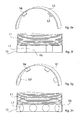
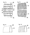
- the object is achieved by at least one protective sheath and / or multiple protective sheaths and / or multiple protective sheath segments, which or in any length and diameter design, in any body shape, for example, a semicircle ( Fig. 1a ), Quarter-arch, arched, C-shaped, elliptical, half-elliptical ( Fig. 1b ) , in regular and irregular polygons ( Fig. 1c ) can be executed or can.
- the protective sheath and / or the protective shells and / or the protective sheath segments can be formed in any way or can eg accordion ( Fig. 1d ), wavy ( Fig. 1e ), smooth ( Fig.
- transversely ribbed, trapezoidal ( Fig. 1f ), rectangular and these formations, can run in any order, for example, vertical, horizontal, diagonal.
- the protective sheath and / or the protective shells and / or the protective sheath segments in any combination or combinations of the body shape can be performed or can.
- Fig. 1g, 1h, 1i and 1j show examples of such embodiments on one and more protective shell segments, in any configuration, arrangement and combination options.
- Fig. 1g shows a semicircular protective sheath segment, in combination of smooth and concertina-shaped training, the accordion-shaped sections are perpendicular.
- Fig. 1h and Fig. 1i each show two semicircular protective sheath segments.
- Fig. 1h shows an example of two protective sheath segments in smooth training, which are suitable for the protection of straight sections of one and more lines.
- Fig. 1i shows an example of two protective shell segments, in concertina-shaped, running vertically, with smooth-shaped end faces, which are suitable for the protection of portions of one and several lines with any curve shape.
- Fig. 1j shows two semicircular protective sheath segments, in accordion-shaped training, run vertically, with smooth formation of the ends or end faces.
- the shape of the semicircle is preferred for a plurality of protective sheath segments which are movable, e.g. accordion-shaped, corrugated and preferably ends at the ends or at the ends in a smooth training.
- protective sheath is intended to stand for a protective sheath, for multiple sheaths and for any number of sheath segments.
- the protective sheath can be provided with one and / or more spacers, in which case the protective sheath and a spacer and / or a plurality of spacers are respectively detachably attached to the line or lines to be protected, and the line or lines to be protected are surrounded circumferentially and at least along a portion of the line or lines between the line to be protected or the lines and the protective jacket, a cavity (safety clearance) is generated.
- a spacer and / or a plurality of spacers may be present, which may be made of any body shape and / or more arbitrary body shapes or which arbitrarily placed on or in the protective sheath and attached in any way, as well factory-incorporated, factory pre-assembled or can be supplied for assembly.
- the spacer and / or the spacers characterized in that this or this along a portion of the line or lines, between the line or the conduits and the protective jacket, in the assembled state, a cavity (safety distance), any measure, generates or generate.
- a cavity safety distance
- any measure generates or generate.
- Fig. 2a, 2b, 2c, 2d . 2e, 2f, 2g, 2h . 2i, and 2y show only a small number of examples of the numerous possible embodiments of one and / or more spacers, of which Fig. 2f, 2h and 2y a perspective view and bottom view of Fig. 2e, 2g and 2i demonstrate.
- Fig. 2a and Fig. 2c each show a spacer.
- This embodiment of the spacer has at least one clamping ring 12, which in any form, for example, a semicircle ( Fig. 2c ), Quarter arch, bow-shaped, C-shaped ( Fig. 2a ), Ellipse-shaped, semi-elliptical, in regular and irregular polygons, which is provided with at least one or more spacer ribs 13 with an outer investor ring 14, which in any shape, for example, a semicircle ( Fig. 2c ), Quarter-arch, arched, C-shaped ( Fig. 2a ), Ellipsoidal, semi-elliptical, may be executed in regular and irregular polygons and has a receiving opening 15 for mounting on the line to be protected or on the lines to be protected.
- Fig. 2b and 2d each show a spacer.
- This embodiment of the spacer has at least one clamping ring 12, which in any form, for example, a semicircle ( Fig. 2d ), Quarter arch, bow-shaped, C-shaped ( Fig. 2b ), Ellipse-shaped, semi-elliptical, may be executed in regular and irregular polygons, which is mounted with at least one or more spacer ribs 13 directly in the inside and / or in the protective jacket 11 (without investor ring 14) and has a receiving opening 15 for mounting.
- clamping ring 12 in any form, for example, a semicircle ( Fig. 2d ), Quarter arch, bow-shaped, C-shaped ( Fig. 2b ), Ellipse-shaped, semi-elliptical, may be executed in regular and irregular polygons, which is mounted with at least one or more spacer ribs 13 directly in the inside and / or in the protective jacket 11 (without investor ring 14) and has a receiving opening 15 for mounting.
- Fig. 2e and Fig. 2g show a further embodiment of a plurality of spacers 16, which consist of several arbitrarily shaped bodies, here for example in the form of Rectangles ( Fig. 2e ) and cylinders ( Fig. 2g ).
- the arbitrarily shaped bodies can be arranged on or in the inside of the protective jacket 11, vertically, horizontally or diagonally.
- the support surface or bearing surfaces 17 represent the line to be protected.
- the support surface or bearing surfaces 17 may be slightly arcuate in order to obtain an optimum adaptation to the line to be protected or to be protected lines, the support surface or the support surfaces, the line or lines to be protected must not touch.
- Fig. 2i shows a further embodiment, a spacer, extending in any body shape on the inside of the protective jacket 11, here for example in the form of a semi-ellipse 16. Wherein the running body forms the bearing surfaces 17 to be protected line or lines to be protected, but not must touch.
- Fig. 2f shows the bottom view of the Fig. 2e
- Fig. 2h shows the bottom view of the Fig. 2g
- Fig. 2j shows the bottom view of the Fig. 2i ,
- Fig. 3p shows a variant, the preferred embodiments of several spacers.
- Fig. 3p shows two spacers 16, each consisting of a square body on the inside of the protective jacket 11 extending.
- the line protection device In order to solve the existing problems of individual adaptation, the line protection device, to the numerous cable diameters of the line or lines to be protected, without manufacturing a specific line protection device specifically for the numerous line diameters and the respective specific properties, it is advantageous to have a device to create, which allows an individual adaptation to a variety of pipe diameters.
- the preferred embodiment of the line protection device includes one or more spacers and one or more devices for individual adaptation to the most varied tube diameters.
- the device is used for individual adaptation, if the outer diameter of the line or lines to be protected, not the inner diameter of the line protection device (protective sheath with spacer) corresponds.
- the required diameter is adjusted and / or by one or more built-in or factory pre-assembled or to be attached devices, by mounting the line protection device Volume of the line to be protected triggers a mechanism or this device is changed so that the Line protection device is fixed to the protected line or lines.
- the device for individual adaptation to a variety of diameters is not needed, ie this is not mounted or removed when this is detachably pre-assembled.
- the circuit protection device (protective sheath with spacer) is to be mounted alone, wherein the support surface of the spacer or spacers has direct contact with the line to be protected.
- the device for individual adaptation to a wide variety of diameters is not releasably attached, it is always used.
- the device for individual adaptation to a wide variety of diameters or the devices for individual adaptation to a wide variety of diameters characterized in that this individual adaptation and fixation of the line protection device or line protection devices to a variety of pipe diameters and their respective specific properties, to be protected Conduction or of lines allows.
- the device or devices for individual adaptation to a variety of diameters carried out in any way, arranged arbitrarily, placed anywhere on or in all elements of this line protection device or line protection devices and can be attached, and incorporated at the factory, factory pre-assembled or for assembly.
- a device or devices can be present or can, which allows a specific function. This device or devices for attachment can or can be performed in any way, arranged arbitrarily, placed anywhere in or on all elements of this line protection device or line protection devices and fixed, as well as factory incorporated, factory pre-assembled or can be included for mounting.
- a possible embodiment of a device or devices for individual adaptation to a wide variety of diameters may consist of several arbitrarily shaped body, which on or inside the protective jacket and / or on or in the spacer and / or on or in the spacers, again detachable , be placed in any order eg vertical, diagonal, horizontal.
- the attachment of the individual body can be done in any way.
- the inner diameter is individually reduced or increased, thus allowing an individual diameter adjustment.
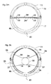
- FIG. 3a shows an example of such an embodiment of a device for individual adaptation to a variety of diameters in the assembled state, on a line to be protected 18 consisting of rectangular shaped bodies 19, preferably in an arcuate design of the support surface 24, to a better fit, at protective line or on the lines to get.
- a plug-in system Fig. 3b
- a sliding system Fig. 3c
- the spacer or protective sheath here, for example, diagonal, are attached.
- the inner diameter is reduced or increased, thus allowing a diameter adjustment, to the desired outer diameter of the line or lines to be protected.
- the support surface 24 represents.
- Another possible embodiment of a device or of devices for individual adaptation to a wide variety of diameters can be made from the use of one or more flexible or elastic materials and / or non-elastic materials which have been given elasticity by the shaping.
- the elastic material or the elastic property molding is respectively placed at the ends on or in the spacer and / or in or at the spacers and / or at or inside the protective jacket.
- the embodiment of a device for individual adaptation to the various diameters, which runs in the line protection device is pressed by the volume of the line or lines, in the direction of the protective jacket. Due to the resulting voltage, the line protection device is fixed to the line or lines to be protected.
- the attachment of this device on or in the protective jacket and / or on or in a spacer and / or on or in the spacers can be done in any way, as well as factory incorporated, factory pre-assembled or enclosed with the assembly.
- Fig. 3d, 3e, 3f, 3g and 3h show examples of such embodiments of a device or devices for individual adaptation to a variety of diameters.
- Fig. 3d shows two protective shell segments 11 attached together, with two spacers 16 which extend on the inside of each protective casing segment 11.
- the spring or the device for individual adaptation to a wide variety of diameters 19, can be additionally provided with a support surface, any shape, for example, here in the form of a rectangle 25, in a slight arcuate design. If no additional bearing surface is incorporated, represent the two springs, even the bearing surface, each with the surface that touches the line to be protected.
- the attachment of this device for individual adaptation to a variety of diameters may be on or in the protective jacket and / or on or in the spacer and / or on or in the spacers, on be made in any way, as well as factory-incorporated, factory pre-assembled or enclosed with the assembly.
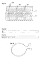
- Fig. 3e, 3f and 3g show other shapes with elastic property.
- Fig. 3e shows a helical compression spring
- Fig. 3f shows a screw tension spring
- Fig. 3g shows a material in corrugated form.
- Fig. 3h shows an example of a usable elastic material, in the embodiment of a wide-shaped rubber.
- a device or devices for individual adaptation to different diameters may consist of several arbitrarily shaped bodies, which on one side, on or in a spacer and / or in or on the spacers and / or in or on the protective jacket , to be placed.
- the attachment can be made in any way, as well as factory incorporated, factory pre-assembled or included with the assembly.
- the other side of the body or arbitrarily shaped ends freely in the interior of the line protection device. Provided that in the installed state, the line protection device, the body, with the free-ending side or surface, with the line to be protected or the lines makes contact.
- the embodiment of a device for individual adaptation to a wide variety of diameters is pressed by the volume of the line or lines, in the direction of the protective jacket. Due to the resulting voltage, the line protection device is fixed to the line to be protected or to the lines.
- 3i, 3j, 3k and 3l show examples of such embodiments, a device or devices for individual adaptation to a variety of diameters, of which Fig. 3j and 3l show a detailed view.
- Fig. 3i shows a side view or detail view of two protective shell segments 11, with two spacers 16, mounted on a line 18 to be protected.
- the angled end is attached to or in the spacer and / or on or in the spacers 16 and / or on or in the protective sheath by plugging.
- the end with arcuate expression ends freely in the interior of the line protection device.
- No. 24 shows, the respective bearing surface, which is pressed in the assembled state, by the volume of the line to be protected, respectively in the direction 47 of the protective jacket and in the direction of the line protection device. Due to the resulting voltage, the entire line protection device is fixed to the line to be protected.
- Fig. 3j shows a detail view of the body, in the form of a rectangle, with a slightly curved pronounced end.
- Fig. 3k shows a side view and detailed view of two protective shell segments 11, with two spacers 16, in the assembled state, without to be protected line.
- the device for individual adaptation to a wide variety of diameters here consisting of two parallel mounted bending springs 19, which are each placed on one side of or in the spacer and / or on or in the spacers and / or on or in the protective jacket and in the assembled state free end in the interior of the line protection device.
- the two bending springs are pressed by the volume of the line to be protected or the lines, respectively in the direction 47 of the protective jacket and in the direction of the line protection device. Due to the resulting voltage, the entire line protection device is fixed to the line to be protected.
- the attachment of the device for individual adaptation to a variety of diameters, of which any number can be used, can be done in any way, as well as factory incorporated, factory pre-assembled or enclosed with the assembly.
- Fig. 3l shows a detail view of a bending spring.
- a device or devices for individual adaptation to a variety of diameters may consist of several arbitrarily shaped and flexible bodies, each on one side of or in the spacer and / or on or in the spacers and / or on or in Protective jacket, can be fixed in any way, as well as pre-assembled at the factory, factory-incorporated or supplied for assembly.
- four arbitrarily shaped bodies represent a unit, a device for individual adaptation to a wide variety of diameters and any number of these units can be used.
- two arbitrarily shaped and flexible bodies may be provided by means of one or more connecting devices in order to grip around the other body and / or to provide any arbitrarily shaped and flexible body with one or more connecting devices.
- Fig. 3m shows an example of such an embodiment of an apparatus for individual adaptation to a variety of diameters.
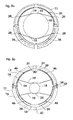
- Fig. 3m shows a side view of two protective shell segments 11, with two spacers 16, in the assembled state, with no line to be protected.
- a device or devices for individual adaptation to a variety of diameters may consist of several flexible or elastic materials, in any body shape.
- the arbitrarily shaped bodies are in each case at the ends on or in the spacer and / or on or in the spacers and / or on or in the inside of the protective jacket and / or by means of a special device or devices located in or on the spacer and / or in or on the spacers and / or on or in the protective jacket, so fastened or attached, that in the mounted state, the flexible or elastic body touches the line to be protected or the lines.
- the embodiment of a device or the devices for individual adaptation to the various diameters which runs in the line protection device, pressed by the volume of the conduit, in the direction of the protective jacket, wherein the ends of the or the arbitrarily shaped body, the Retain position and / or change position. Due to the resulting voltage, the line protection device is fixed to the line to be protected.
- the attachment of this device or the devices for individual adaptation to a variety of diameters can be done in any way, as well as include a special or additional device or fixtures for attachment, which allows a specific function. From this device for individual adaptation to a wide variety of diameters, can be used as many as desired, as well as incorporated at the factory, factory pre-assembled or enclosed with the assembly.
- Fig. 3n . 3o and Fig. 3p show examples of such preferred embodiments of a device or devices for individual adaptation to a variety of diameters.
- Fig. 3n shows a side view of two protective casing segments 11, with two spacers 16, each consisting of a square body, here on the inside, the respective protective casing segment 11 extending, in the assembled state, on a line to be protected 18.
- This device for stationary attachment for example, by means of a receiving device 27, which allows the introduction and attachment of the device for individual adaptation to different diameters, without shortening or mobility of the ends of the flexible bodies required and / or by means of insertion holes ( Fig. 3o No. 28), which requires at one end or the ends of the flexible bodies a mobility, at least one end, which allows a time-wise shortening of one or more ends to allow the fastening or insertion into the insertion holes and the decrease. Furthermore, it would be possible to attach the device for individual adaptation to a variety of diameters by means of hoes, eyes or the like, so that the ends can be fixed stationary.
- the embodiment of a device for individual adaptation to the various diameters 19, which runs in the line protection device is pressed by the volume of the line 18, in the direction of the protective jacket. Whereby the ends of the or the arbitrarily shaped body, maintain the position. Due to the resulting voltage, the line protection device is fixed to the line to be protected.
- this embodiment of a device for individual adaptation to a wide variety of diameters can be used, as well as incorporated at the factory, pre-assembled at the factory or supplied for assembly.
- Fig. 3p shows a side view of two protective shell segments 11, with two spacers 16, each consisting of a square body, run on the inside, the protective jacket 11, in the mounted state, on a line to be protected 18.
- the device for individual adaptation to the different diameters 19th In this embodiment, each consists of two flexible body, in a slight w-like training and arbitrary shaping of the ends, here in T-shaped design.
- one or more guide rails 29 are attached to fix the device for individual adaptation to the most varied diameters 19, which are placed arbitrarily on or in the spacer and / or on or in the spacers and / or on or in the inside of the protective jacket and can run continuously and / or in sections .
- the flexible body When using a continuous guide rail, the flexible body is inserted at the respective open ends of the guide rail. Are the guide rails only partially extending, the resulting space 31 can be used in addition to the assembly 30 of the flexible body by each compressed the ends of the flexible body, and positioned in the free space 30 and inserted into guide rails 29.
- the embodiment of a device for individual adaptation to the various diameters 19, which runs in the line protection device is pressed by the volume of the line 18 and the lines, in the direction of the protective jacket. Wherein the ends of the arbitrarily shaped body 19, the position in the guide rail or guide notes change and run in opposite directions. Due to the resulting voltage, the line protection device is fixed to the line to be protected. From this embodiment of a device for individual adaptation to a wide variety of diameters can be used as many, as well as factory pre-assembled or enclosed with the assembly.
- each type of closure whether incorporated at the factory, factory pre-assembled or for external attachment, is suitable.
- Fig. 4a and 4b show examples of factory-incorporated closure options.
- Fig. 4d, 4e and 4f show examples of external closure options.
- Fig. 4c show the Figures 4d, 4e and 4f in the applied state.
- Fig. 4a shows an example of a preferred embodiment of a closure option, if there are a plurality of spacers consisting of a plurality of closure members and mating closure members, which are preferably incorporated directly into or on the spacers and / or attached as an extension to the spacers.
- the respective closure member 32 has a latching nose 34 which is inserted into the counter-locking member 33 designed as a locking cage. To the closure member 32 and counter-locking member 33, to solve again, pressure is exerted on the locking lugs 34.
- Fig. 4b shows a further embodiment of a closure possibility, consisting of a plurality of closure members and mating closure members, which are arbitrarily positioned and mounted on the outside of the line protection device.
- the closure member 32 has a latching nose 34 which is inserted into the counter-locking member 33 designed as a locking cage.
- the closure members and counter-locking members can be arbitrarily positioned on the protective jacket and fixed in any manner, for example by means of a connection which allows pivoting.
- Fig. 4c shows examples of externally mounted closure options on two protective shell segments 11.
- No. 35 shows a possible closure variant by means of cable trimmers
- No. 36 shows a possible closure variant by means of cable ties
- No. 37 by means of Velcro strips.
- Fig. 4f shows a detail view of a cable cutter, corresponding to No. 35.
- Fig. 4d shows a detail view of a cable tie, corresponding to No. 36.
- Fig. 4e shows a detailed view of a Velcro tape, corresponding to No. 37.
- the protective jacket and / or the protective shells and / or protective sheath segments and the selected closure variant or their placement it may be advantageous to provide the protective sheath and / or the protective shells and / or the protective sheath segments, with a device which a lateral prevents slipping.
- This device which prevents slipping sideways, can be carried out in any way and find any number of uses and is characterized in that it prevents or prevent lateral slippage or opening up of the line protection device.
- Fig. 5a and 5b show examples of such a device, which prevents lateral slippage.
- Fig. 5a shows a detailed views of two protective sheath segments 11. Where a protective sheath segment on the longitudinal edge one or more extensions in the form of a pin or stabilizing pin 38 and the other protective sheath segment at the opposite position or points has a counter recess 39 or have. When the protective sheath segments are closed, the stabilizing pin or pins 38 are inserted into the opposing counterbore or counterbores 39.
- Fig. 5b shows a detailed views of two protective casing segments 11.
- a protective casing segment along the longitudinal edge, on the outside and / or inside of the protective casing segment has one or more stabilizing pins 38, in any length and shape or have. After mounting the line protection device, this stabilizing pin 38 or these stabilizing pins prevents lateral slippage and brings during assembly the advantage that no precise insertion into a counter-recess or counter-recesses is required.
- One of the other possibilities would be to attach a plurality of stabilizing pins to the respective longitudinal edges of a protective sheath and / or protective sheaths and / or protective sheath segments.
- Fig. 5c shows two interconnected protective sheath segments 11, wherein a protective shroud segment is here provided with an externally mounted stabilizing pin 38, in the middle of the line protector length.
- the protective sheaths and / or the protective sheath segments it is advantageous to provide a device which allows a juxtaposition or joining adjacent, immediately adjacent protective shells and / or protective sheath segments, which can be performed in any way.
- Fig. 6a, 6b, 6c and 6d show examples of possible embodiments of such a device for juxtaposing or connecting adjacent, immediately adjacent protective sheaths and / or protective sheath segments.
- Fig. 6a and Fig. 6b shows an example of a detailed view of two interconnected protective sheath segments 11, which have on the front side of the protective sheath segments, a device for connecting adjacent, immediately adjacent protective shells and / or protective sheath segments.
- Fig. 6a shows two interconnected protective sheath segments 11, which at one end face with Any number of lugs 40 are provided.
- Fig. 6b shows two interconnected protective sheath segments 11, which are provided on an end face with any number of counter-recesses, the nose mold 41.
- Fig. 6a and 6b are connected by merging the lugs 40 and the respective counter-recess in nose-shaped 41 with each other.
- Fig. 6c and Fig. 6d shows an example of a detailed view of two interconnected protective sheath segments 11, which have on the front side of the protective sheath segments, a device for connecting adjacent, immediately adjacent protective shells or protective sheath segments.
- Fig. 6c has a plurality of closure members, each with a latching lug 42.
- Fig. 6d has a plurality of counter-locking members 43 in the form of a cage, for latching the locking lug on.
- the closure members with locking lug 42 and the counter-locking members 43 can be arbitrarily placed and fixed in any way, and be pivotally fixed eg by means of pin connections 44 or fixed.
- the line protection device which are characterized in that the special finishing protective sheaths and / or the final protection sheath segments, in any length and diameter configuration, in any body shape, e.g. semicircle, quarter-arch, arcuate, C-shaped, elliptical, semi-elliptical, non-circular, in regular and irregular polygons, the end caps and / or the end shields segments being of any type e.g. accordion-shaped, corrugated, smooth, cross-ribbed, trapezoidal, rectangular, and these formations may run in any arrangement, e.g. vertical, horizontal, diagonal.
- the special finishing protective sheaths and / or the final protection sheath segments in any length and diameter configuration, in any body shape, e.g. semicircle, quarter-arch, arcuate, C-shaped, elliptical, semi-elliptical, non-circular, in regular and irregular polygons
- the end caps and / or the end shields segments being of any type e.
- the design, the arrangement, the length and diameter can be performed. But no spacer or spacers and / or no device or devices for individual adaptation to a wide variety of pipe diameters must be included.
- any type of attachment is possible, which allows a juxtaposition or a connection.
- this attachment which allows a juxtaposition or a connection, it may be necessary, in order to prevent sufficient stability or solving to provide these calendarterrorismmäntel and / or the considered legion labor costsegmente with a device which connect to each other or close allows.
- Fig. 7a, 7b, 7c and 7d show examples of possible embodiments of a plurality of end protective sheath segments and examples of mounting options for lining up adjacent, immediately adjacent protective sheath or adjacent protective sheath segments and examples of a device of the lock together.
- Fig. 7a shows two end protective sheath segments 45, in combination of concertina-like and smooth training, in the body shape of a semicircle.
- the two end protective sheath segments 45 of Fig. 7a show two examples of a device of closing together, at the longitudinal edge of the end protection shell segments.
- No. 32 shows a closure member with locking lug 34, which connects or closes by inserting into the counter-closure member 33, the two end protection shell segments.
- No. 40 shows a nose which, by insertion into the counter recess 41, connects or closes off two end protective sheath segments.
- Fig. 7b shows two relievetikmantelsegmente 45, in accordion-like design and horizontal, slightly diagonal arrangement, in the form of a semi-circle, which has a diameter reduction on one end face.
- This concertina-shaped design, in a horizontal, slightly diagonal arrangement, allows additional flexibility to reduce the diameter.
- On the other end face is a device which allows the juxtaposition, adjacent adjacent protective sheath or adjacent protective sheath segments, here in the form of lugs 40.
- Fig. 7c shows a closure protective sheath segment 45, in a smooth design, in the form of a semi-circle, which has on one end a diameter reduction and on the other end a device which the juxtaposing, on adjacent immediately adjacent protective sheath or of adjacent protective sheath segments, here in the form of Noses, in angular shape 40.
- Fig. 7d shows a cover shell segment 45, in accordion-like design and vertical arrangement or vertically extending, in the form of a semi-circle, which has a diameter reduction on one end face.
- the concertina-shaped training in a vertical arrangement an additional flexibility for length adjustment is possible.
- At the other end side there is a device, which allows the juxtaposition, on adjacent directly adjacent protective sheath or of adjacent protective sheath segments, here in the form of lugs, in cube-like form 40th
- Fig. 8 shows an example of such an embodiment, a device with hinge-like property, on two semi-circular body shapes 11, which are connected to each other by means of an embossment 48, here of the same material, with each other.
- the line protection device or line protection devices with their numerous variations and elements can be additionally provided with ventilation slots or ventilation chambers and / or perforations, any shape, any size and arrangement.
- Fig. 3p shows an example of incorporated ventilation slots 46.
- line protection devices or line protection devices can be made of any suitable material or material and material combinations, as well as in any color, nuance and color combinations.
Landscapes
- Engineering & Computer Science (AREA)
- Architecture (AREA)
- Civil Engineering (AREA)
- Structural Engineering (AREA)
- General Engineering & Computer Science (AREA)
- Mechanical Engineering (AREA)
- Details Of Indoor Wiring (AREA)
- Flexible Shafts (AREA)
- Suspension Of Electric Lines Or Cables (AREA)
- Catching Or Destruction (AREA)
- Train Traffic Observation, Control, And Security (AREA)
Abstract
Description
Die Erfindung betrifft eine Leitungsschutzvorrichtung bzw. Leitungsschutzvorrichtungen zum Schutze von einer und mehreren Leitungen jeglicher Art, insbesondere zum Schutze der Leitungen von Kraftfahrzeugen und des täglichen Lebensbereiches, vor Tierverbiss und/oder zur allgemeinen Bündelung von Leitungen, jeglicher Art und/oder zur Umhüllung von einer und mehreren Leitungen, jeglicher Art, zur farblichen Veränderung und optischen Verschönerung.The invention relates to a line protection device or line protection devices for the protection of one and more lines of any kind, in particular for the protection of the lines of motor vehicles and the daily life, against animal bite and / or for the general bundling of lines, of any kind and / or the wrapping of a and several lines, of any kind, for color change and optical beautification.
Speziell elektrische Leitungen und Fluidleitungen, beispielsweise Kühlmittelschläuche, werden insbesondere bei Nachts im Freien abgestellter Autos von Mardern durch Verbiss beschädigt, um dies zu vermeiden, ist es bekannt, den Motorraum schlupfdicht abzuzäunen, elektrisch aufladbare Drähte zu verlegen oder die Leitungen mit Schutzhülsen zu versehen. Diese Maßnahmen sind aufwendig oder können einen Marderverbiss nicht immer wirksam vermeiden.Specifically, electric lines and fluid lines, such as coolant hoses, especially at night in the open parked cars of Mardern damaged by biting, to avoid this, it is known to fend off the engine compartment slip-tight, to lay electrically rechargeable wires or to provide the lines with protective sleeves. These measures are complex or can not always effectively avoid a marten banisher.
Der Erfindung liegt die Aufgabe zugrunde, eine Leitungsschutzvorrichtung bzw. Leitungsschutzvorrichtungen zu schaffen, welche:
- ■ Sicheren Schutz vor Beschädigung durch Tierverbiss an Leitungen, jeder Art, bietet.
- ■ Sicheren Schutz für alle Leitungen eines jeden Kfz-Typen bietet, ohne hierbei spezifisch auf jede einzelne Leitung oder der Leitungen eines jeweiligen Kfz-Modells einzugehen.
- ■ Sich individuell an die unterschiedlichsten Leitungsdurchmesser, an Biegeradien bzw. Kurvenformen, an beliebigen Höhen- und Tiefenunterschieden, sogar an unterschiedliche Leitungsdurchmesser einer einzigen Leitung entlang und sich der individuellen Länge der Leitung bzw. von Leitungen problemlos anpassen lässt, ohne dabei spezifisch für die vielzähligen Leitungsdurchmesser und den jeweiligen spezifischen Eigenschaften, eine eigene Leitungsschutzvorrichtung zu fertigen.
- ■ Es ermöglicht Hindernisse problemlos, ohne Sicherheitseinbussen, zu überbrücken.
- ■ Es ermöglicht die Montage und Abnahme, ohne Werkzeugeinsatz schnell und unkompliziert durchzuführen, vor allem ohne zwischenzeitliches Lösen eines Endes oder der Enden der Leitung bzw. der Leitungen.
- ■ Wiederverwendbar ist.
- ■ Es ermöglicht kostenintensive und zeitaufwendige Reparaturen, fatale Folgeschäden durch Tierverbiss sicher zu vermeiden und geplagte Autobesitzer vor erneuten Angriffen schützt.
- ■ Es ermöglicht den Ansprüchen des Marktes gerecht zu werden, die Wünsche der Kunden vor allem der Handhabung und Eigenschaften zu erfüllen und eine sofortige Kaufentscheidung zu ermöglichen, ohne dabei Herstellungskostenintensiv und Vermarktungsaufwendig zu sein.
- ■ Die erfindungsgemäße Vorrichtung eignet sich zum Schutz von Leitungen jeder Art z.B. Hochspannungszündleitungen, Kühlmittelleitungen, Kraftstoffschläuchen, Schläuchen und Schlauchleitungen für Treibgasanlagen, Niederspannungskabeln, Bremsschläuchen, Schläuchen an Vergasern und Einspritzsystemen, Leitungen für Klimaanlagen, Schläuchen für Scheibenwaschanlagen, Elektroleitungen, diversen Schläuchen, Antennenkabeln und vielem mehr.
- ■ Die erfindungsgemäße Vorrichtung eignet sich zur Umhüllung von einer und mehreren Leitungen, jeglicher Art, zur farblichen Veränderung und optischen Verschönerung.
- ■ Die erfindungsgemäße Vorrichtung eignet sich zur Bündelung von Leitungen jeder Art z.B. als Kabelkanal zur Bündelung von Computerkabeln, Telefonkabel, Faxkabel, Stromkabel, Druckerkabel, Kabel von Fernsehgeräten, Stereoanlagen und vielem mehr.
- ■ Provides reliable protection against damage from biting animals on pipes, of any kind.
- ■ Provides safe protection for all types of wires of any vehicle type, without specifically addressing each individual wire or the wires of a given car model.
- ■ Individually adaptable to a wide variety of pipe diameters, bend radii or curve shapes, any differences in height and depth, even to different pipe diameters of a single line and the individual length of the line or lines without being specific to the many Cable diameter and the specific properties to manufacture its own line protection device.
- ■ It allows obstacles to be bridged without any loss of safety.
- ■ It allows assembly and acceptance without the use of tools quickly and easily, especially without intermediate loosening of an end or the ends of the pipe or lines.
- ■ Reusable.
- ■ It allows costly and time-consuming repairs to safely avoid fatal consequential damage through animal biting and protects plagued car owners from re-attacks.
- ■ It enables to meet the demands of the market, to fulfill the wishes of the customers above all the handling and characteristics and to enable an immediate purchase decision, without being manufacturing cost intensive and marketing consuming.
- ■ The device of the invention is suitable for the protection of lines of any kind eg Hochspannungszündleitungen, coolant lines, fuel hoses, hoses and hose lines for LPG systems, low-voltage cables, brake hoses, carburetor and injection systems hoses, cables for air conditioning systems, hoses for windscreen washer systems, electrical cables, various hoses, antenna cables and much more.
- The device according to the invention is suitable for wrapping one or more lines, of any kind, for color change and optical embellishment.
- The device according to the invention is suitable for bundling lines of any kind, for example as a cable channel for bundling computer cables, telephone cables, fax cables, power cables, printer cables, cables of television sets, stereos and much more.
Die nachfolgenden Beispiele sollen die vorliegende Erfindung unter Bezugnahme auf die Zeichnungen verdeutlichen, ohne sie einzuschränken, in diesen zeigen:
- Fig. 1a, 1b und 1c
- jeweils eine Perspektivansicht von einem Schutzmantelsegment, in verschiedenen Ausführungen der Körperform.
- Fig. 1d, 1e und 1f
- jeweils eine Vorderansicht eines Schutzmantelsegmentes, in verschiedenartigen Ausbildungen.
- Fig. 1g
- eine Vorderansicht eines Schutzmantelsegmentes, in Kombination von verschiedenen Ausbildungen.
- Fig. 1h und 1i
- jeweils eine Vorderansicht bzw. Perspektivansicht von zwei Schutzmantelsegmenten, in Kombination von verschiedenartigen Ausbildungen.
- Fig. 1j
- eine Vorderansicht bzw. Perspektivansicht von zwei Schutzmantelsegmenten.
- Fig. 2a und 2c
- jeweils eine Seitenansicht einer Ausführungsart einer Abstandhalterung bzw. von Abstandshalterungen.
- Fig. 2b und 2d
- eine Seitenansicht bzw. Perspektivansicht einer Leitungsschutzvorrichtung mit verschiedenen Ausführungsarten einer Abstandshalterung bzw. von Abstandshalterungen.
- Fig. 2e, 2g und 2i
- eine Seitenansicht bzw. Perspektivansicht von Variationsmöglichkeiten von einem oder mehreren Abstandshhalterungen.
- Fig. 2f, 2h und 2j
- eine Unteransicht der
Fig. 2e, 2g und2i - Fig. 3a
- eine Seitenansicht bzw. Perspektivansicht einer Variante einer Vorrichtung zur individuellen Anpassung an die unterschiedlichsten Durchmesser.
- Fig. 3 b und 3c
- eine Seitenansicht bzw. perspektivische Detailansicht jeweils einer Variante einer Vorrichtung zur individuellen Anpassung an die unterschiedlichsten Durchmesser.
- Fig. 3d, 3i, 3k, 3m, 3n, 3o und 3p
- eine Seitenansicht bzw. Perspektivansicht jeweils einer Variante einer Vorrichtung zur individuellen Anpassung an die unterschiedlichsten Durchmesser.
- Fig. 3e, 3f, 3g, 3h, 3j und 31
- jeweils eine perspektivische Detailansicht, einer Variante einer Vorrichtung zur individuellen Anpassung an die unterschiedlichsten Durchmesser.
- Fig. 4a und 4b
- jeweils eine Vorderansicht bzw. Perspektivansicht von zwei Schutzmantelsegmenten, mit werkseitig eingearbeiteten bzw. werkseitig vormontierten Verschlussmöglichkeiten.
- Fig. 4c
- eine Vorderansicht von zwei Schutzmantelsegmenten mit, extern angebrachten Verschlussmöglichkeiten.
- Fig. 4d, 4e und 4f
- jeweils eine Draufsicht von externen Verschlussmöglichkeiten.
- Fig. 5 a und 5b
- eine Vorderansicht bzw. eine Detailansicht von jeweils zwei Schutzmantelsegmenten, mit verschiedenen Ausführungsarten einer Vorrichtung, welche ein seitliches verrutschen verhindert.
- Fig. 5c
- eine Vorderansicht bzw. Perspektivansicht einer Leitungsschutzvorrichtung im zusammengestecktem Zustand, mit einer Ausführungsart einer Vorrichtung, welche ein seitliches verrutschen verhindert.
- Fig. 6a, 6b, 6c und 6d
- jeweils eine Vorderansicht bzw. Perspektivansicht von jeweils zwei miteinander verbundenen Schutzmantelsegmenten, welche mit verschiedenen Ausführungsarten einer Vorrichtung zur Aneinanderreihung bzw. zur Verbindung benachbarter, unmittelbar angrenzender Schutzmäntel eingearbeitet bzw. werkseitig vormontiert sind.
- Fig. 7a, 7b, 7c und 7d
- jeweils eine Vorderansicht bzw. Perspektivansicht von ein oder mehrere Abschlussschutzmantelsegmenten, wovon
Fig. 7a zusätzlich verschiedene Ausführungsarten einer Vorrichtung des miteinander Verbindens bzw. des miteinander verschliessen aufzeigt. - Fig. 8
- eine Perspektivansicht von zwei halbkreisförmigen Körperformen, welche mittels einer Prägung miteinander beweglich verbunden sind.
- Fig. 1a, 1b and 1c
- in each case a perspective view of a protective casing segment, in various embodiments of the body shape.
- Fig. 1d, 1e and 1f
- in each case a front view of a protective casing segment, in various configurations.
- Fig. 1g
- a front view of a protective shell segment, in combination of different configurations.
- Fig. 1h and 1i
- in each case a front view or perspective view of two protective shell segments, in combination of different types of training.
- Fig. 1j
- a front view and perspective view of two protective shell segments.
- Fig. 2a and 2c
- each a side view of an embodiment of a spacer or spacers.
- Fig. 2b and 2d
- a side view and perspective view of a line protection device with different embodiments of a spacer or spacers.
- Fig. 2e, 2g and 2i
- a side view or perspective view of variations of one or more Abstandshhalterungen.
- Fig. 2f, 2h and 2j
- a bottom view of the
Fig. 2e, 2g and2i - Fig. 3a
- a side view and perspective view of a variant of a device for individual adaptation to a variety of diameters.
- Fig. 3 b and 3c
- a side view and perspective detail view of a variant of a device for individual adaptation to a variety of diameters.
- Fig. 3d, 3i, 3k, 3m, 3n, 3o and 3p
- a side view and perspective view of a variant of a device for individual adaptation to a variety of diameters.
- 3e, 3f, 3g, 3h, 3j and 31st
- in each case a perspective detail view of a variant of a device for individual adaptation to a wide variety of diameters.
- Fig. 4a and 4b
- in each case a front view or perspective view of two protective shell segments, with factory-incorporated or factory pre-assembled closure options.
- Fig. 4c
- a front view of two protective shell segments with externally mounted closure options.
- Fig. 4d, 4e and 4f
- each a plan view of external closure options.
- Fig. 5 a and 5b
- a front view and a detailed view of two protective shell segments, with different embodiments of a device which prevents lateral slippage.
- Fig. 5c
- a front view and a perspective view of a line protection device in the mated state, with an embodiment of a device which prevents lateral slippage.
- Fig. 6a, 6b, 6c and 6d
- in each case a front view or perspective view of two interconnected protective shell segments, which are incorporated with different embodiments of a device for juxtaposing or for connecting adjacent, immediately adjacent protective coats or factory pre-assembled.
- Fig. 7a, 7b, 7c and 7d
- in each case a front view or perspective view of one or more end protection shell segments, of which
Fig. 7a additionally various embodiments of a device of interconnecting or closing together shows. - Fig. 8
- a perspective view of two semi-circular body shapes, which are connected to each other by means of an embossing movable.
Die Aufgabe wird gelöst durch mindestens einen Schutzmantel und/oder mehreren Schutzmäntel und/oder mehreren Schutzmantelsegmenten, welcher bzw. welche in beliebiger Länge- und Durchmessergestaltung, in jeglicher Körperform z.B. eines Halbkreises (
Insbesondere wird die Form des Halbkreises für mehrere Schutzmantelsegmente bevorzugt, welche beweglich ausgebildet sind z.B. ziehharmonikaförmig, gewellt und vorzugsweise an den Stirnseiten bzw. an den Enden in glatter Ausbildung enden.In particular, the shape of the semicircle is preferred for a plurality of protective sheath segments which are movable, e.g. accordion-shaped, corrugated and preferably ends at the ends or at the ends in a smooth training.
Um die weitere Formulierung in dieser Patentschrift zu vereinfachen soll der Begriff "Schutzmantel" für einen Schutzmantel, für mehrere Schutzmäntel und für beliebige Anzahl von Schutzmantelsegmenten stehen.To simplify the further formulation in this specification, the term "protective sheath" is intended to stand for a protective sheath, for multiple sheaths and for any number of sheath segments.
Der Schutzmantel kann mit einem und/oder mehreren Abstandshalterungen versehen sein, wobei dann der Schutzmantel und ein Abstandshalter und/oder mehrere Abstandshalterungen jeweils auf die zu schützende Leitung bzw. Leitungen, wieder lösbar aufgesteckt werden und die zu schützende Leitung bzw. Leitungen umfänglich umgeben und zumindest entlang eines Abschnittes der Leitung bzw. der Leitungen zwischen der zu schützenden Leitung bzw. den Leitungen und dem Schutzmantel ein Hohlraum (Sicherheitsabstand) erzeugt wird.The protective sheath can be provided with one and / or more spacers, in which case the protective sheath and a spacer and / or a plurality of spacers are respectively detachably attached to the line or lines to be protected, and the line or lines to be protected are surrounded circumferentially and at least along a portion of the line or lines between the line to be protected or the lines and the protective jacket, a cavity (safety clearance) is generated.
Erfindungsgemäß kann also ein Abstandshalter und/oder mehrere Abstandshalterungen vorhanden sein, welche aus einer beliebigen Körperform und/oder mehreren beliebigen Körperformen ausgeführt sein kann bzw. können, welcher bzw. welche beliebig am oder im Schutzmantel platziert und auf jede Art und Weise befestigt, sowie werkseitig eingearbeitet, werkseitig vormontiert oder zur Montage beliegen kann bzw. können.According to the invention, therefore, a spacer and / or a plurality of spacers may be present, which may be made of any body shape and / or more arbitrary body shapes or which arbitrarily placed on or in the protective sheath and attached in any way, as well factory-incorporated, factory pre-assembled or can be supplied for assembly.
Der Abstandshalter und/oder die Abstandshalterungen, ist dadurch gekennzeichnet, das dieser oder diese entlang eines Abschnittes der Leitung bzw. der Leitungen, zwischen der Leitung bzw. den Leitungen und dem Schutzmantel, im montierten Zustand, ein Hohlraum (Sicherheitsabstand), beliebigen Maßes, erzeugt bzw. erzeugen. Wobei die Auflagefläche bzw. Auflageflächen des Abstandshalters und/oder der Abstandshalterungen im montierten Zustand die Leitung nicht unbedingt berühren muss.The spacer and / or the spacers, characterized in that this or this along a portion of the line or lines, between the line or the conduits and the protective jacket, in the assembled state, a cavity (safety distance), any measure, generates or generate. Where the support surface or contact surfaces of the spacer and / or the spacers in the mounted state, the line must not necessarily touch.
Um das bestehende Probleme der individuellen Anpassung, der Leitungsschutzvorrichtung, an die vielzähligen Leitungsdurchmesser der zu schützenden Leitung bzw. Leitungen zu lösen, ohne dabei spezifisch für die vielzähligen Leitungsdurchmesser und den jeweiligen spezifischen Eigenschaften eine eigene Leitungsschutzvorrichtung zu fertigen, ist es von Vorteil, eine Vorrichtung zu schaffen, welche eine individuelle Anpassung an die unterschiedlichsten Leitungsdurchmesser ermöglicht.In order to solve the existing problems of individual adaptation, the line protection device, to the numerous cable diameters of the line or lines to be protected, without manufacturing a specific line protection device specifically for the numerous line diameters and the respective specific properties, it is advantageous to have a device to create, which allows an individual adaptation to a variety of pipe diameters.
Eine solche Vorrichtung zur individuellen Anpassung an die unterschiedlichsten Durchmesser, bringt zugleich die Vorteile einer perfekten Passform und Haltbarkeit, an geraden und beliebigen Kurvenformen mit sich. Vor allem löst diese das Problem der Überbrückung von unterschiedlichsten Durchmessern an einer einzigen Leitung entlang. Weitere Vorteile bestehen in der Entgegenwirkung von Geräuschentwicklung, der Regulierbarkeit von Engstellen und der Geringhaltung der Herstellungskosten.Such a device for individual adaptation to a variety of diameters, brings at the same time the advantages of a perfect fit and durability, in straight and arbitrary waveforms with it. Above all, this solves the problem of bridging different diameters along a single line. Further advantages are the counteracting of noise development, the controllability of bottlenecks and the low cost of production.
Die bevorzugte Ausführungsart der Leitungsschutzvorrichtung beinhaltet ein oder mehrere Abstandshalterungen und eine oder mehrere Vorrichtungen zur individuellen Anpassung an die Unterschiedlichsten Leitungsdurchmesser. In diesem Fall kommt die Vorrichtung zur individuellen Anpassung zum Einsatz, wenn der Außendurchmesser der zu schützenden Leitung oder der Leitungen, nicht dem Innendurchmesser der Leitungsschutzvornchtung (Schutzmantel mit Abstandshalter) entspricht. Je nach Ausführungsart dieser Vorrichtung zur individuellen Anpassung an die unterschiedlichsten Durchmesser, wird z.B. durch das Hinzufügen oder Lösen dieser Vorrichtung der benötige Durchmesser eingestellt und/oder durch eine oder mehrere eingebaute bzw. werkseitig vormontierte oder anzubringende Vorrichtungen, die bei Montage der Leitungsschutzvorrichtung, durch das Volumen der zu schützenden Leitung einen Mechanismus auslöst bzw. diese Vorrichtung sich so verändert, das die Leitungsschutzvorrichtung, an der zu schützenden Leitung bzw. den Leitungen, fixiert wird.The preferred embodiment of the line protection device includes one or more spacers and one or more devices for individual adaptation to the most varied tube diameters. In this case, the device is used for individual adaptation, if the outer diameter of the line or lines to be protected, not the inner diameter of the line protection device (protective sheath with spacer) corresponds. Depending on the embodiment of this device for individual adaptation to a wide variety of diameters, eg by adding or releasing this device, the required diameter is adjusted and / or by one or more built-in or factory pre-assembled or to be attached devices, by mounting the line protection device Volume of the line to be protected triggers a mechanism or this device is changed so that the Line protection device is fixed to the protected line or lines.
Entspricht der Außendurchmesser der zu schützenden Leitung bzw. der Leitungen, dem Innendurchmesser der Leitungsschutzvorrichtung, wird die Vorrichtung zur individuellen Anpassung an die unterschiedlichsten Durchmesser nicht benötigt d.h. diese wird nicht montiert oder abgenommen, wenn diese wieder lösbar vormontiert ist. In diesem Fall ist die Leitungsschutzvorrichtung (Schutzmantel mit Abstandshalter) alleinig anzubringen, wobei die Auflagefläche des oder der Abstandshalterungen direkten Kontakt mit der zu schützenden Leitung aufweist. In diesem Falle erzeugt der Abstandshalter oder die Abstandshalterungen zwischen der zu schützenden Leitung bzw. der Leitungen und dem Schutzmantel einen Hohlraum (Sicherheitsabstand), zumindest entlang eines Abschnittes der zu schützenden Leitung bzw. der zu schützenden Leitungen.
Ist aber die Vorrichtung zur individuellen Anpassung an die unterschiedlichsten Durchmesser nicht wieder lösbar angebracht, so wird diese immer verwendet.Corresponds to the outer diameter of the line to be protected or the lines, the inner diameter of the line protection device, the device for individual adaptation to a variety of diameters is not needed, ie this is not mounted or removed when this is detachably pre-assembled. In this case, the circuit protection device (protective sheath with spacer) is to be mounted alone, wherein the support surface of the spacer or spacers has direct contact with the line to be protected. In this case, creates the spacer or the spacers between the line to be protected or the lines and the protective sheath a cavity (safety distance), at least along a portion of the line to be protected or the lines to be protected.
However, if the device for individual adaptation to a wide variety of diameters is not releasably attached, it is always used.
Die Vorrichtung zur individuellen Anpassung an die unterschiedlichsten Durchmesser bzw. die Vorrichtungen zur individuellen Anpassung an die unterschiedlichsten Durchmesser, ist dadurch gekennzeichnet, das diese eine individuelle Anpassung und Fixierung der Leitungsschutzvorrichtung bzw. Leitungsschutzvorrichtungen an die unterschiedlichsten Leitungsdurchmesser und deren jeweiligen spezifischen Eigenschaften, der zu schützenden Leitung bzw. von Leitungen ermöglicht. Wobei die Vorrichtung bzw. die Vorrichtungen zur individuellen Anpassung an die unterschiedlichsten Durchmesser, auf jede Art und Weise ausgeführt, beliebig angeordnet, beliebig an oder in allen Elementen dieser Leitungsschutzvorrichtung bzw. Leitungsschutzvorrichtungen platziert und befestigt sein kann bzw. können, sowie werkseitig eingearbeitet, werkseitig vormontiert oder zur Montage beliegen können. Wobei zur Befestigung der Vorrichtung bzw. der Vorrichtungen zur individuellen Anpassung an die unterschiedlichsten Durchmesser, zusätzlich eine Vorrichtung bzw. Vorrichtungen vorhanden sein kann bzw. können, welche eine bestimmte Funktion ermöglicht. Diese Vorrichtung bzw. Vorrichtungen zur Befestigung kann bzw. können auf jede Art und Weise ausgeführt, beliebig angeordnet, beliebig in oder an allen Elementen dieser Leitungsschutzvorrichtung bzw. Leitungsschutzvorrichtungen platziert und befestigt sein, sowie werkseitig eingearbeitet, werkseitig vormontiert oder zur Montage beiliegen können.The device for individual adaptation to a wide variety of diameters or the devices for individual adaptation to a wide variety of diameters, characterized in that this individual adaptation and fixation of the line protection device or line protection devices to a variety of pipe diameters and their respective specific properties, to be protected Conduction or of lines allows. Wherein the device or devices for individual adaptation to a variety of diameters, carried out in any way, arranged arbitrarily, placed anywhere on or in all elements of this line protection device or line protection devices and can be attached, and incorporated at the factory, factory pre-assembled or for assembly. Wherein, for the attachment of the device or the devices for individual adaptation to a wide variety of diameters, in addition, a device or devices can be present or can, which allows a specific function. This device or devices for attachment can or can be performed in any way, arranged arbitrarily, placed anywhere in or on all elements of this line protection device or line protection devices and fixed, as well as factory incorporated, factory pre-assembled or can be included for mounting.
Eine mögliche Ausführungsart einer Vorrichtung bzw. von Vorrichtungen zur individuellen Anpassung an die unterschiedlichsten Durchmesser kann aus mehreren beliebig geformten Körper bestehen, welche an oder in der Innenseite des Schutzmantels und/oder am oder im Abstandhalter und/oder an oder in den Abstandshalterungen, wieder lösbar, in beliebiger Anordnung angebracht werden z.B. senkrecht, diagonal, waagrecht. Die Befestigung der einzelnen Körper kann auf jede Art und Weise erfolgen. Durch das Hinzufügen oder Lösen der einzelnen Körper, wird der Innendurchmesser individuell verringert oder vergrößert und somit eine individuelle Durchmessereinstellung ermöglicht.
Eine weitere mögliche Ausführungsart einer Vorrichtung bzw. von Vorrichtungen zur individuellen Anpassung an die unterschiedlichsten Durchmesser kann aus der Verwendung eines oder mehreren flexiblen bzw. elastischen Materialien und/oder von nicht elastischen Materialien, welche durch die Formgebung eine Elastizität erhielt bzw. erhielten, erfolgen. Das flexible bzw. elastische Material oder die Formgebung mit elastischer Eigenschaft, wird jeweils an den Enden am oder im Abstandshalter und/oder in oder an den Abstandshalterungen und/oder an oder in der Innenseite des Schutzmantels platziert. Bei Montage der Leitungsschutzvorrichtung wird die Ausführungsart einer Vorrichtung zur individuellen Anpassung an die unterschiedlichsten Durchmesser, die in der Leitungsschutzvorrichtung verläuft, durch das Volumen der Leitung bzw. der Leitungen, in Richtung des Schutzmantel gedrückt. Durch die entstandene Spannung wird die Leitungsschutzvorrichtung, an der zu schützenden Leitung bzw. den Leitungen fixiert. Die Befestigung dieser Vorrichtung am oder im Schutzmantel und/oder an oder in einem Abstandshalter und/oder an oder in den Abstandshalterungen, kann auf jede Art und Weise erfolgen, sowie werkseitig eingearbeitet, werkseitig vormontiert sein oder zur Montage beiliegen.Another possible embodiment of a device or of devices for individual adaptation to a wide variety of diameters can be made from the use of one or more flexible or elastic materials and / or non-elastic materials which have been given elasticity by the shaping. The elastic material or the elastic property molding is respectively placed at the ends on or in the spacer and / or in or at the spacers and / or at or inside the protective jacket. When mounting the line protection device, the embodiment of a device for individual adaptation to the various diameters, which runs in the line protection device, is pressed by the volume of the line or lines, in the direction of the protective jacket. Due to the resulting voltage, the line protection device is fixed to the line or lines to be protected. The attachment of this device on or in the protective jacket and / or on or in a spacer and / or on or in the spacers can be done in any way, as well as factory incorporated, factory pre-assembled or enclosed with the assembly.
Eine weitere mögliche Ausführungsart einer Vorrichtung bzw. von Vorrichtungen zur individuellen Anpassung an die unterschiedlichsten Durchmesser kann aus mehreren beliebig geformten Körpern bestehen, welche an einer Seite, am oder in einem Abstandshalter und/oder in oder an den Abstandshalterungen und/oder in oder am Schutzmantel, platziert werden. Die Befestigung kann auf jede Art und Weise erfolgen, sowie werkseitig eingearbeitet, werkseitig vormontiert oder zur Montage beiliegen. Die andere Seite des bzw. der beliebig geformten Körper, endet frei, im Innenleben der Leitungsschutzvorrichtung. Unter der Vorraussetzung, das im montierten Zustand, der Leitungsschutzvorrichtung, der Körper, mit der frei endenden Seite bzw. Fläche, mit der zu schützenden Leitung bzw. den Leitungen ein Kontakt herstellt. Durch das Volumen der zu schützenden Leitung bzw. der Leitungen wird die Ausführungsart einer Vorrichtung zur individuellen Anpassung an die unterschiedlichsten Durchmesser durch das Volumen der Leitung bzw. der Leitungen, in Richtung des Schutzmantels gedrückt. Durch die entstandene Spannung wird die Leitungsschutzvorrichtung an der zu schützenden Leitung bzw. an den Leitungen fixiert.Another possible embodiment of a device or devices for individual adaptation to different diameters may consist of several arbitrarily shaped bodies, which on one side, on or in a spacer and / or in or on the spacers and / or in or on the protective jacket , to be placed. The attachment can be made in any way, as well as factory incorporated, factory pre-assembled or included with the assembly. The other side of the body or arbitrarily shaped ends freely in the interior of the line protection device. Provided that in the installed state, the line protection device, the body, with the free-ending side or surface, with the line to be protected or the lines makes contact. Due to the volume of the line or lines to be protected, the embodiment of a device for individual adaptation to a wide variety of diameters is pressed by the volume of the line or lines, in the direction of the protective jacket. Due to the resulting voltage, the line protection device is fixed to the line to be protected or to the lines.
Eine weitere mögliche Ausführungsart einer Vorrichtung bzw. von Vorrichtungen zur individuellen Anpassung an die unterschiedlichsten Durchmesser kann aus mehreren beliebig geformten und flexiblen Körpern bestehen, welche jeweils an einer Seite am oder im Abstandshalter und/oder an oder in den Abstandshalterungen und/oder am oder im Schutzmantel, auf jede Art und Weise befestigt werden, sowie werkseitig vormontiert, werkseitig eingearbeitet oder zur Montage beliegen können. Wobei vorzugsweise vier beliebig geformte Körper eine Einheit, einer Vorrichtung zur individuellen Anpassung an die unterschiedlichsten Durchmesser darstellen und von dieser Einheit beliebig viele verwendet werden können. In dieser Ausführungsart können z.B. jeweils zwei beliebig geformte und flexible Körpern mittels einer oder mehreren Verbindungsvorrichtung versehen sein, um den anderen Körper zu umgreifen und/oder jeder beliebig geformte und flexible Körper mit einer oder mehreren Verbindungsvorrichtungen versehen sein. Unter der Vorraussetzung, das jeweils zwei Körpern, durch ihre jeweilige bzw. jeweiligen Verbindungsvorrichtungen, welche sich im montierten Zustand oberhalb und unterhalb der zu schützenden Leitung bzw. von Leitungen befinden, durch das Volumen der Leitung bzw. der Leitungen eine Spannung ergeben, die wiederum eine Fixierung an die unterschiedlichsten Durchmesser einer schützenden Leitung bzw. von Leitungen ermöglicht.Another possible embodiment of a device or devices for individual adaptation to a variety of diameters may consist of several arbitrarily shaped and flexible bodies, each on one side of or in the spacer and / or on or in the spacers and / or on or in Protective jacket, can be fixed in any way, as well as pre-assembled at the factory, factory-incorporated or supplied for assembly. Preferably, four arbitrarily shaped bodies represent a unit, a device for individual adaptation to a wide variety of diameters and any number of these units can be used. In this embodiment, e.g. in each case two arbitrarily shaped and flexible bodies may be provided by means of one or more connecting devices in order to grip around the other body and / or to provide any arbitrarily shaped and flexible body with one or more connecting devices. Provided that two bodies each, through their respective or respective connecting devices, which are in the mounted state above and below the line or lines to be protected, result in a voltage through the volume of the line or lines, which in turn allows a fixation to the different diameters of a protective line or lines.
Von dieser Vorrichtung zur individuellen Anpassung an die unterschiedlichsten Durchmesser werden, so angebracht, das diese bei Montage auf die zu schützenden Leitung, jeweils 2 miteinander verbundene Körper oberhalb der Leitung und jeweils 2 miteinander verbundene Körper sich unterhalb der zu schützenden Leitung bzw. der Leitungen befinden. Von dieser Vorrichtung bestehend aus 4 Körpern, können beliebig viele verwendet werden, wobei diese am oder in einem Abstandshalter und/oder in oder an mehreren Abstandshalterungen und/oder am oder im Schutzmantel platziert und auf jede Art und Weise befestigt, sowie werkseitig vormontiert, werkseitig eingearbeitet oder zur Montage beliegen können. Bei Montage der Leitungsschutzvorrichtung auf die zu schützende Leitung, wird durch das Volumen der zu schützenden Leitung bzw. der Leitungen, diese Vorrichtung bzw. Vorrichtungen zur individuellen Anpassung an die unterschiedlichsten Durchmesser, jeweils in Richtung des Schutzmantels gedrückt. Durch die entstandene Spannung, wird die gesamte Leitungsschutzvorrichtung an der zu schützenden Leitung bzw. Leitungen fixiert.From this device for individual adaptation to a variety of diameters are, so attached, these are when mounted on the line to be protected, each two interconnected body above the line and each two interconnected body are below the line to be protected or the lines , Of this device consisting of 4 bodies, any number can be used, these being placed on or in a spacer and / or in or on a plurality of spacers and / or on or in the protective jacket and fixed in any way, as well as factory pre-assembled, factory incorporated or for assembly. When mounting the line protection device on the line to be protected, is pressed by the volume of the line or lines to be protected, this device or devices for individual adaptation to a variety of diameters, respectively in the direction of the protective jacket. Due to the resulting voltage, the entire line protection device is fixed to the line or lines to be protected.
Eine weitere mögliche und bevorzugte Ausführungsart einer Vorrichtung bzw. von Vorrichtungen zur individuellen Anpassung an die unterschiedlichsten Durchmesser kann aus mehreren flexiblen bzw. elastischen Materialien, in beliebiger Körperform, bestehen. Die beliebig geformten Körper werden jeweils an den Enden am oder im Abstandshalter und/oder an oder in den Abstandshalterungen und/oder an oder in der Innenseite des Schutzmantels und/oder mittels einer speziellen Vorrichtung bzw. Vorrichtungen, die sich in oder am Abstandshalter und/oder in oder an den Abstandshalterungen und/oder am oder im Schutzmantel befindet, so befestigt bzw. angebracht, dass im montierten Zustand, die flexiblen bzw. elastischen Körper, die zu schützende Leitung bzw. die Leitungen berührt. Bei Montage der Leitungsschutzvorrichtung wird die Ausführungsart einer Vorrichtung bzw. die Vorrichtungen zur individuellen Anpassung an die unterschiedlichsten Durchmesser, die in der Leitungsschutzvorrichtung verläuft, durch das Volumen der Leitung, in Richtung des Schutzmantel gedrückt, wobei die Enden des oder der beliebig geformten Körper, die Position beibehalten und/oder ihre Position verändern können. Durch die entstandene Spannung wird die Leitungsschutzvorrichtung, an der zu schützenden Leitung fixiert. Die Befestigung dieser Vorrichtung bzw. der Vorrichtungen zur individuellen Anpassung an die unterschiedlichsten Durchmesser kann auf jede Art und Weise erfolgen, sowie eine spezielle bzw. zusätzliche Vorrichtung bzw. Vorrichtungen zur Befestigung beinhalten, welche eine bestimmte Funktion ermöglicht. Von dieser Vorrichtung zur individuellen Anpassung an die unterschiedlichsten Durchmesser, können beliebig viele Verwendung finden, sowie werkseitig eingearbeitet, werkseitig vormontiert oder zur Montage beiliegen.Another possible and preferred embodiment of a device or devices for individual adaptation to a variety of diameters may consist of several flexible or elastic materials, in any body shape. The arbitrarily shaped bodies are in each case at the ends on or in the spacer and / or on or in the spacers and / or on or in the inside of the protective jacket and / or by means of a special device or devices located in or on the spacer and / or in or on the spacers and / or on or in the protective jacket, so fastened or attached, that in the mounted state, the flexible or elastic body touches the line to be protected or the lines. When mounting the line protection device, the embodiment of a device or the devices for individual adaptation to the various diameters, which runs in the line protection device, pressed by the volume of the conduit, in the direction of the protective jacket, wherein the ends of the or the arbitrarily shaped body, the Retain position and / or change position. Due to the resulting voltage, the line protection device is fixed to the line to be protected. The attachment of this device or the devices for individual adaptation to a variety of diameters can be done in any way, as well as include a special or additional device or fixtures for attachment, which allows a specific function. From this device for individual adaptation to a wide variety of diameters, can be used as many as desired, as well as incorporated at the factory, factory pre-assembled or enclosed with the assembly.
Um den Schutzmantel und/oder die Schutzmäntel und/oder mehrere Schutzmantelsegmente bei Montage auf die zu schützende Leitung, miteinander zu verbinden bzw. zu schließen, ist jede Verschlussart, ob werkseitig eingearbeitet, werkseitig vormontiert oder zur externen Anbringung, geeignet.In order to connect or close the protective jacket and / or the protective sheaths and / or several protective sheath segments when mounted on the line to be protected, each type of closure, whether incorporated at the factory, factory pre-assembled or for external attachment, is suitable.
Je nach Ausführungsart des Schutzmantels und/oder der Schutzmäntel und/oder Schutzmantelsegmenten und der gewählten Verschlussvariante bzw. deren Platzierung kann es von Vorteil sein, den Schutzmantel und/oder die Schutzmäntel und/oder die Schutzmantelsegmenten, mit einer Vorrichtung zu versehen, welche ein seitliches verrutschen verhindert.Depending on the embodiment of the protective jacket and / or the protective shells and / or protective sheath segments and the selected closure variant or their placement, it may be advantageous to provide the protective sheath and / or the protective shells and / or the protective sheath segments, with a device which a lateral prevents slipping.
Diese Vorrichtung welche ein seitliches verrutschen verhindert, kann auf jede Art und Weise ausgeführt sein und beliebig viele Verwendung finden und ist dadurch gekennzeichnet, das diese ein seitliches Verrutschen bzw. Aufklaffen der Leitungsschutzvorrichtung verhindert bzw. verhindern.This device which prevents slipping sideways, can be carried out in any way and find any number of uses and is characterized in that it prevents or prevent lateral slippage or opening up of the line protection device.
Eine der weiteren Möglichkeiten wäre, mehrere Stabilisierungsstifte an den jeweiligen Längskanten eines Schutzmantels und/oder von Schutzmänteln und/oder von Schutzmantelsegmenten anzubringen.One of the other possibilities would be to attach a plurality of stabilizing pins to the respective longitudinal edges of a protective sheath and / or protective sheaths and / or protective sheath segments.
Je nach Ausführungsart der Schutzmäntel und/oder der Schutzmantelsegmente ist es von Vorteil eine Vorrichtung zu schaffen, welche eine Aneinanderreihung bzw. ein Verbinden benachbarter, unmittelbar angrenzender Schutzmäntel und/oder von Schutzmantelsegmenten ermöglicht, welche auf jede Art und Weise ausgeführt sein können.Depending on the embodiment of the protective sheaths and / or the protective sheath segments, it is advantageous to provide a device which allows a juxtaposition or joining adjacent, immediately adjacent protective shells and / or protective sheath segments, which can be performed in any way.
Weiterhin besteht die Möglichkeit, einen speziellen Abschluss, der Leitungsschutzvorrichtung zur Verfügung zu stellen, welche dadurch gekennzeichnet sind, dass die speziellen Abschlussschutzmäntel und/oder die Abschlussschutzmantelsegmente, in beliebiger Länge- und Durchmessergestaltung, in jeglicher Körperform z.B. eines Halbkreises, Viertelbogens, Bogenförmig, C-Förmig, Ellipsenförmig, Halbellipsenförmig, Unrunde, in regelmäßigen und unregelmäßigen Vielecken ausgeführt sein können, wobei die Abschlussschutzmäntel und/oder die Abschlussschutzmantelsegmente in jeglicher Art ausgebildet z.B. ziehharmonikaförmig, gewellt, glatt, quergerippt, trapezförmig, rechteckig und diese Ausbildungen in beliebiger Anordnung verlaufen können z.B. vertikal, horizontal, diagonal. Sowie die Abschlussschutzmäntel und/oder Abschlussschutzmantelsegmente in beliebiger Kombination bzw. Kombinationen der Körperform, der Ausbildung, der Anordnung, der Länge und Durchmesser ausgeführt sein können. Wobei aber kein Abstandshalter bzw. Abstandshalterungen und/oder keine Vorrichtung bzw. Vorrichtungen zur individuellen Anpassung an die unterschiedlichsten Leitungsdurchmesser enthalten sein muss.Furthermore, it is possible to provide a special termination, the line protection device, which are characterized in that the special finishing protective sheaths and / or the final protection sheath segments, in any length and diameter configuration, in any body shape, e.g. semicircle, quarter-arch, arcuate, C-shaped, elliptical, semi-elliptical, non-circular, in regular and irregular polygons, the end caps and / or the end shields segments being of any type e.g. accordion-shaped, corrugated, smooth, cross-ribbed, trapezoidal, rectangular, and these formations may run in any arrangement, e.g. vertical, horizontal, diagonal. As well as the completion guards and / or Abschlussschutzmantelsegmente in any combination or combinations of the body shape, the design, the arrangement, the length and diameter can be performed. But no spacer or spacers and / or no device or devices for individual adaptation to a wide variety of pipe diameters must be included.
Zur Befestigung der Abschlussschutzmäntel und/oder der Abschlussschutzmantelsegmente an den unmittelbar angrenzendem Schutzmantel bzw. angrenzenden Schutzmantelsegmenten, ist jede Art der Befestigung möglich, welche eine Aneinanderreihung bzw. ein Verbinden ermöglicht. Je nach Ausführungsart dieser Befestigung, welche ein Aneinanderreihen bzw. ein Verbinden ermöglich, kann es erforderlich sein, um ausreichend Stabilität bzw. ein Lösen zu verhindern auch diese Abschlussschutzmäntel und/oder die Abschlussschutzmantelsegmente mit einer Vorrichtung zu versehen, welche ein miteinander verbinden bzw. schließen ermöglicht.To attach the Abschlussschutzmäntel and / or the Abschlussschutzmantelsegmente to the immediately adjacent protective jacket or adjacent protective sheath segments, any type of attachment is possible, which allows a juxtaposition or a connection. Depending on the embodiment of this attachment, which allows a juxtaposition or a connection, it may be necessary, in order to prevent sufficient stability or solving to provide these Abschlussschutzmäntel and / or the Abschlussschutzmantelsegmente with a device which connect to each other or close allows.
Die zwei Abschlussschutzmantelsegmente 45 der
Weiterhin wäre es möglich an einer Längskante am oder im Schutzmantel und/oder an oder in den Schutzmänteln und/oder an oder in den Schutzmantelsegmenten und/oder an oder in den Abschlussschutzmänteln und/oder an oder in den Abschlussschutzmantelsegmenten und/oder an oder in einem Abstandshalter und/oder an oder in den Abstandshalterungen, Vorrichtungen beliebigen Maßes und Anzahl einzuarbeiten, werkseitig zu montieren oder zur Montage beizulegen, welche die gleichen Eigenschaften von Scharnieren aufweisen.Furthermore, it would be possible on one longitudinal edge on or in the protective jacket and / or on or in the protective sheaths and / or on or in the protective sheath segments and / or on or in the protective cover shrouds and / or on or in the protective shroud segments and / or on or in a Spacers and / or on or in the spacers to incorporate devices of any size and number, factory-mount or attach for assembly, which have the same properties of hinges.
Die Leitungsschutzvorrichtung bzw. Leitungsschutzvorrichtungen mit ihren vielzähligen Variationsmöglichkeiten und Elementen können zusätzlich mit Lüftungsschlitzen oder Lüftungskammern und/oder Perforierungen, beliebiger Formgebung, beliebiger Größe und Anordnung, versehen sein.
Alle Elemente und Ihre vielzähligen möglichen Ausführungsarten, dieser Leitungsschutzvorrichtung bzw. Leitungsschutzvorrichtungen kann bzw. können aus jedem geeigneten Material bzw. Materialien und Materialkombinationen, sowie in jeder Farbgebung, Nuancierung und Farbkombinationen hergestellt werden.All of the elements and their numerous possible embodiments, these line protection devices or line protection devices can be made of any suitable material or material and material combinations, as well as in any color, nuance and color combinations.
- 1111
- Schutzmantel oder SchutzmantelsegmentProtective jacket or protective jacket segment
- 1212
- Klammerring einer AbstandshalterungClamping ring of a spacer
- 1313
- Abstandsrippe einer AbstandshalterungSpacer rib of a spacer
- 1414
- Anlegering einer AbstandshalterungInvestoring a spacer
- 1515
- Aufnahmeöffnungreceiving opening
- 1616
- Ausführungsart eines oder mehrer AbstandshalterungenEmbodiment of one or more spacers
- 1717
- Auflagefläche einer AbstandshalterungSupport surface of a spacer
- 1818
- Leitungmanagement
- 1919
- Vorrichtung zur individuellen Anpassung an die unterschiedlichsten LeitungsdurchmesserDevice for individual adaptation to the most varied cable diameters
- 2020
- Nasenose
- 2121
- Gegenvertiefung der NaseCounter-depression of the nose
- 2222
- Schienerail
- 2323
- Gegenvertiefung der SchieneCounterbore of the rail
- 2424
- Auflagefläche, der Vorrichtung zur individuellen Anpassung an die unterschiedlichsten LeitungsdurchmesserSupport surface, the device for individual adaptation to a variety of pipe diameters
- 2525
- Zusätzliche eingearbeitete Auflagefläche, der Vorrichtung zur individuellen Anpassung an die unterschiedlichsten LeitungsdurchmesserAdditional built-in support surface, the device for individual adaptation to a variety of cable diameters
- 2626
- Schienerail
- 2727
- Aufnahmevorrichtungcradle
- 2828
- Einführlochinsertion
- 2929
- Führungsschieneguide rail
- 3030
- Freiraumfree space
- 3131
- Voll-Linie, zur Kennzeichnung des FreiraumesFull line, for the marking of the free space
- 3232
- Verschlussorganclosure member
- 3333
- GegenverschlussorganAgainst closure member
- 3434
- Rastnaselocking lug
- 3535
- KabeldrillerTwist Locks
- 3636
- Kabelbindercable ties
- 3737
- Klettbandvelcro
- 3838
- Vorrichtung zur Vermeidung des seitlichen VerrutschensDevice for avoiding lateral slippage
- 3939
- Gegenvertiefung einer Vorrichtung zur Vermeidung des seitlichen VerrutschensCounter-recess of a device for preventing lateral slippage
- 4040
- Vorrichtung zur Aneinanderreihung bzw. zur Verbindung an benachbarten unmittelbar angrenzenden Schutzmantel und/oder Schutzmantelsegmenten, in Form einer NaseDevice for stringing together or for connection to adjacent immediately adjacent protective sheath and / or protective sheath segments, in the form of a nose
- 4141
- Gegenvertiefung zu Nr. 40Counter recess to No. 40
- 4242
- Vorrichtung zur Aneinanderreihung bzw. zur Verbindung an benachbarten unmittelbar angrenzenden Schutzmantel und/oder Schutzmantelsegmenten, in Form eines Verschlussorgans mit RastnaseApparatus for stringing together or for connection to adjacent immediately adjacent protective sheath and / or protective sheath segments, in the form of a closure member with locking lug
- 4343
- Gegenverschlussorgan zu Nr. 42Counter-obturator to No. 42
- 4444
- Stiftverbindungpin connection
- 4545
- AbschlussmantelsegmentClosure shell segment
- 4646
- Lüftungsschlitzvent
- 4747
- Pfeil, zur Anzeige der RichtungsbewegungArrow, to indicate the directional movement
- 4848
- Prägung mit Scharnierähnlicher EigenschaftEmbossment with hinge-like property
Claims (6)
- Line protection device for the protection of at least one cable line (18) of any type, especially for the protection of cables in motor vehicles and in general usage, from animal bites and/or for bundling and/or for covering at least one single cable line (18), in which the line protection device has a protective casing (11) and/or segments of protective casing that can be designed for any length and diameter and for any shape, in which at least a spacer and/or at least one device for individual adjustment to different diameters and, in which, as the case may be, additionally at least one device is provided that prevents lateral dislocation or gaping of the protective casing and/or that of the segments of the protective casing, is characterized in that:a) the device for individual adjustment to different diameters consists of at least two springs(19);b) the additional device has two parallel running rails (26) each, that run along side or inside the line protection device.
- Line protection device as per Claim 1 is furthermore characterized in that the two parallel running rails (26) provided with insertion holes.
- Line protection device as per Claim 1 or 2 is furthermore characterized in that the springs (19) are designed as two helical compression springs and/or two helical tension springs and/or at least two rubber fittings, which are placed parallel to each other and in which the two ends can be fixed to the opposite sides on or inside the line protection device.
- Line protection device as per Claim 3 is furthermore characterized in that the springs (19) can be provided with an additional supporting base, preferably of a slightly arch shape.
- Line protection device as per Claim 3 is furthermore characterized in that the springs (19) are designed as at least two flex springs which are each positioned in mirror images and laterally reversed and which can be fixed on one side in any manner, on or inside the line protection device and the other end terminates freely inside the line protection device.
- Line protection device as per Claim 3 is furthermore characterized in that the springs are designed as at least two flexible bodies, in w-like shape, having any shape on both ends, preferably in a T-shape which are positioned in mirror images to each other and both the ends, that can be fixed in a movable or stationary position on or inside the line protection device.
Applications Claiming Priority (2)
| Application Number | Priority Date | Filing Date | Title |
|---|---|---|---|
| DE102004018313A DE102004018313A1 (en) | 2004-04-13 | 2004-04-13 | Electric and fluid lines, such as coolant hoses, protection device e.g. for motor vehicles, comprises protective wall or protective wall segments of any length or diameter |
| DE102004018313 | 2004-04-13 |
Publications (3)
| Publication Number | Publication Date |
|---|---|
| EP1587193A2 EP1587193A2 (en) | 2005-10-19 |
| EP1587193A3 EP1587193A3 (en) | 2006-08-02 |
| EP1587193B1 true EP1587193B1 (en) | 2010-06-16 |
Family
ID=34585430
Family Applications (1)
| Application Number | Title | Priority Date | Filing Date |
|---|---|---|---|
| EP05005776A Expired - Lifetime EP1587193B1 (en) | 2004-04-13 | 2005-03-16 | Wire protection device |
Country Status (3)
| Country | Link |
|---|---|
| EP (1) | EP1587193B1 (en) |
| AT (1) | ATE471587T1 (en) |
| DE (2) | DE102004018313A1 (en) |
Cited By (2)
| Publication number | Priority date | Publication date | Assignee | Title |
|---|---|---|---|---|
| DE102020005082B3 (en) | 2020-09-02 | 2021-10-14 | G-quadrat Geokunststoffgesellschaft mbH | Flexible textile structure, floor construction element with a flexible textile structure, method for producing a floor construction element, earth line protection system and method for producing an earth line protection system and use of the floor construction element |
| EP4112967A1 (en) * | 2021-06-28 | 2023-01-04 | Nexans | Vibration absorber |
Families Citing this family (4)
| Publication number | Priority date | Publication date | Assignee | Title |
|---|---|---|---|---|
| ES2258934B1 (en) * | 2005-12-09 | 2007-06-16 | Tom Hutchinson | ELEMENT OF LOCAL CABLE PROTECTION. |
| JP5638939B2 (en) * | 2010-12-28 | 2014-12-10 | 矢崎総業株式会社 | Wire harness and method of manufacturing wire harness |
| CN111963915B (en) * | 2020-08-13 | 2025-01-03 | 安徽信息工程学院 | A flashlight structure |
| CN119400488B (en) * | 2024-11-06 | 2025-08-05 | 东莞顺辉电业制品有限公司 | Composite stranded wire reinforced core cable and preparation method thereof |
Family Cites Families (11)
| Publication number | Priority date | Publication date | Assignee | Title |
|---|---|---|---|---|
| FR1344705A (en) * | 1963-01-16 | 1963-11-29 | Atlas Copco Ab | Mounting and support device for electric cables |
| DE1881159U (en) * | 1963-07-18 | 1963-10-24 | E Vogelsang Fa Dipl Ing Dr | CABLE PROTECTION TUBE. |
| GB2009523B (en) * | 1977-09-13 | 1982-07-07 | Owen W J | Trunking systems for conduits or cables |
| FR2591306B1 (en) * | 1985-12-09 | 1988-07-22 | Bourreau Bruno | METHOD FOR THE PRODUCTION OF A FIXED NETWORK FOR TRANSPORTING FLUID IN A BUILDING, GUIDANCE AND HOLDING DEVICE FOR THE PRODUCTION OF SUCH A NETWORK, AND NETWORK OBTAINED BY THIS PROCESS |
| DE19751611A1 (en) * | 1996-06-05 | 1999-05-27 | Georg Krain | Installation channel with sheet covering used for e.g. indirect interior lighting system |
| US5800762A (en) * | 1996-12-06 | 1998-09-01 | Bethel; Eunice A. | Process for decorating electrical cords |
| GB9713598D0 (en) * | 1997-06-28 | 1997-09-03 | T & N Technology Ltd | Flexible protective sleeve |
| DE10031692A1 (en) * | 2000-06-29 | 2002-01-10 | Alsta Aluminium Und Stahl Gmbh | Plug fit system has parts consisting of corrugated flat material bent into U-profile with arms on both sides of base; arms of one plug fit part rest on arms of another plug fit part |
| GB2365941A (en) * | 2000-08-16 | 2002-02-27 | Balmoral Group | Protective sleeving |
| WO2002054553A2 (en) * | 2001-01-02 | 2002-07-11 | Barry Howard | Cable installations and components therefor |
| DE10139740C1 (en) * | 2001-08-13 | 2003-04-17 | Schlemmer Gmbh | Pipe connection part for corrugated pipes with internal damping element |
-
2004
- 2004-04-13 DE DE102004018313A patent/DE102004018313A1/en not_active Withdrawn
-
2005
- 2005-03-16 DE DE502005009742T patent/DE502005009742D1/en not_active Expired - Lifetime
- 2005-03-16 AT AT05005776T patent/ATE471587T1/en active
- 2005-03-16 EP EP05005776A patent/EP1587193B1/en not_active Expired - Lifetime
Cited By (2)
| Publication number | Priority date | Publication date | Assignee | Title |
|---|---|---|---|---|
| DE102020005082B3 (en) | 2020-09-02 | 2021-10-14 | G-quadrat Geokunststoffgesellschaft mbH | Flexible textile structure, floor construction element with a flexible textile structure, method for producing a floor construction element, earth line protection system and method for producing an earth line protection system and use of the floor construction element |
| EP4112967A1 (en) * | 2021-06-28 | 2023-01-04 | Nexans | Vibration absorber |
Also Published As
| Publication number | Publication date |
|---|---|
| DE502005009742D1 (en) | 2010-07-29 |
| DE102004018313A1 (en) | 2005-06-16 |
| ATE471587T1 (en) | 2010-07-15 |
| EP1587193A3 (en) | 2006-08-02 |
| EP1587193A2 (en) | 2005-10-19 |
Similar Documents
| Publication | Publication Date | Title |
|---|---|---|
| DE60019475T2 (en) | Wire harness protection that snaps over the cables | |
| DE102018217839B4 (en) | Wire harness protection device and wire harness manufacturing method | |
| EP0268869B1 (en) | Synthetic protective tubing device for conduits | |
| DE112013003678B4 (en) | wire protection element | |
| EP2832943A1 (en) | Concealed hinge with electrical connection | |
| DE10050565A1 (en) | Wire bending mechanism for wire harness for slide door of motor vehicle, has pair of projections formed on link arm that are fitted into recesses formed on other link arm | |
| DE112019002841T5 (en) | Wiring harness | |
| EP1587193B1 (en) | Wire protection device | |
| EP3488498A1 (en) | Retaining frame assembly having main frame and securing element and fitting method | |
| DE112013004193T5 (en) | Guiding structure for electrical cables | |
| DE102009030798A1 (en) | Protective device for flexible elements | |
| EP0535712B1 (en) | Wire harness or wire channel, particularly for a motor vehicle | |
| DD265449A1 (en) | CABLE AND TUBING TOW | |
| DE102016112758A1 (en) | HOLDING COMPONENT AND METHOD FOR FASTENING ELECTRICAL WIRES AND LINEAR ASSEMBLY IN A VEHICLE | |
| DE202014101359U1 (en) | End fastening part for cable guide device | |
| EP1119087B1 (en) | Flush mounted box for cable conduits | |
| DE102014109270B4 (en) | Cable fixation, plug with a cable fixation and method for fixing an electrical cable to a plug | |
| EP0709252B1 (en) | Wire harness for incorporation into a vehicle body | |
| DE202004013160U1 (en) | Full-load interface for motor vehicles has a plug connector and a jack designed as a flat casing to slide onto the plug connector | |
| DE102014004931A1 (en) | Spacer means | |
| DE102004005310B4 (en) | Split cylinder tube as protective cover for electrical cables in motor vehicles has projections on opposite edges of slit held together by separate gripper | |
| DE102020208965A1 (en) | Charging cable for an electric vehicle | |
| DE19943763C5 (en) | Protective cover for an electric cable | |
| DE102012020105A1 (en) | Cable management device for use in the installation of cables | |
| DE102018109476A1 (en) | cable holder |
Legal Events
| Date | Code | Title | Description |
|---|---|---|---|
| PUAI | Public reference made under article 153(3) epc to a published international application that has entered the european phase |
Free format text: ORIGINAL CODE: 0009012 |
|
| AK | Designated contracting states |
Kind code of ref document: A2 Designated state(s): AT BE BG CH CY CZ DE DK EE ES FI FR GB GR HU IE IS IT LI LT LU MC NL PL PT RO SE SI SK TR |
|
| AX | Request for extension of the european patent |
Extension state: AL BA HR LV MK YU |
|
| PUAL | Search report despatched |
Free format text: ORIGINAL CODE: 0009013 |
|
| AK | Designated contracting states |
Kind code of ref document: A3 Designated state(s): AT BE BG CH CY CZ DE DK EE ES FI FR GB GR HU IE IS IT LI LT LU MC NL PL PT RO SE SI SK TR |
|
| AX | Request for extension of the european patent |
Extension state: AL BA HR LV MK YU |
|
| 17P | Request for examination filed |
Effective date: 20070202 |
|
| AKX | Designation fees paid |
Designated state(s): AT BE BG CH CY CZ DE DK EE ES FI FR GB GR HU IE IS IT LI LT LU MC NL PL PT RO SE SI SK TR |
|
| GRAP | Despatch of communication of intention to grant a patent |
Free format text: ORIGINAL CODE: EPIDOSNIGR1 |
|
| GRAS | Grant fee paid |
Free format text: ORIGINAL CODE: EPIDOSNIGR3 |
|
| GRAA | (expected) grant |
Free format text: ORIGINAL CODE: 0009210 |
|
| AK | Designated contracting states |
Kind code of ref document: B1 Designated state(s): AT BE BG CH CY CZ DE DK EE ES FI FR GB GR HU IE IS IT LI LT LU MC NL PL PT RO SE SI SK TR |
|
| REG | Reference to a national code |
Ref country code: CH Ref legal event code: EP |
|
| REG | Reference to a national code |
Ref country code: IE Ref legal event code: FG4D Free format text: LANGUAGE OF EP DOCUMENT: GERMAN |
|
| REF | Corresponds to: |
Ref document number: 502005009742 Country of ref document: DE Date of ref document: 20100729 Kind code of ref document: P |
|
| REG | Reference to a national code |
Ref country code: NL Ref legal event code: VDEP Effective date: 20100616 |
|
| PG25 | Lapsed in a contracting state [announced via postgrant information from national office to epo] |
Ref country code: SE Free format text: LAPSE BECAUSE OF FAILURE TO SUBMIT A TRANSLATION OF THE DESCRIPTION OR TO PAY THE FEE WITHIN THE PRESCRIBED TIME-LIMIT Effective date: 20100616 Ref country code: LT Free format text: LAPSE BECAUSE OF FAILURE TO SUBMIT A TRANSLATION OF THE DESCRIPTION OR TO PAY THE FEE WITHIN THE PRESCRIBED TIME-LIMIT Effective date: 20100616 |
|
| LTIE | Lt: invalidation of european patent or patent extension |
Effective date: 20100616 |
|
| PG25 | Lapsed in a contracting state [announced via postgrant information from national office to epo] |
Ref country code: FI Free format text: LAPSE BECAUSE OF FAILURE TO SUBMIT A TRANSLATION OF THE DESCRIPTION OR TO PAY THE FEE WITHIN THE PRESCRIBED TIME-LIMIT Effective date: 20100616 Ref country code: SI Free format text: LAPSE BECAUSE OF FAILURE TO SUBMIT A TRANSLATION OF THE DESCRIPTION OR TO PAY THE FEE WITHIN THE PRESCRIBED TIME-LIMIT Effective date: 20100616 |
|
| PG25 | Lapsed in a contracting state [announced via postgrant information from national office to epo] |
Ref country code: CY Free format text: LAPSE BECAUSE OF FAILURE TO SUBMIT A TRANSLATION OF THE DESCRIPTION OR TO PAY THE FEE WITHIN THE PRESCRIBED TIME-LIMIT Effective date: 20100616 Ref country code: PL Free format text: LAPSE BECAUSE OF FAILURE TO SUBMIT A TRANSLATION OF THE DESCRIPTION OR TO PAY THE FEE WITHIN THE PRESCRIBED TIME-LIMIT Effective date: 20100616 Ref country code: GR Free format text: LAPSE BECAUSE OF FAILURE TO SUBMIT A TRANSLATION OF THE DESCRIPTION OR TO PAY THE FEE WITHIN THE PRESCRIBED TIME-LIMIT Effective date: 20100917 |
|
| REG | Reference to a national code |
Ref country code: IE Ref legal event code: FD4D |
|
| PG25 | Lapsed in a contracting state [announced via postgrant information from national office to epo] |
Ref country code: IE Free format text: LAPSE BECAUSE OF FAILURE TO SUBMIT A TRANSLATION OF THE DESCRIPTION OR TO PAY THE FEE WITHIN THE PRESCRIBED TIME-LIMIT Effective date: 20100616 Ref country code: NL Free format text: LAPSE BECAUSE OF FAILURE TO SUBMIT A TRANSLATION OF THE DESCRIPTION OR TO PAY THE FEE WITHIN THE PRESCRIBED TIME-LIMIT Effective date: 20100616 Ref country code: EE Free format text: LAPSE BECAUSE OF FAILURE TO SUBMIT A TRANSLATION OF THE DESCRIPTION OR TO PAY THE FEE WITHIN THE PRESCRIBED TIME-LIMIT Effective date: 20100616 |
|
| PG25 | Lapsed in a contracting state [announced via postgrant information from national office to epo] |
Ref country code: RO Free format text: LAPSE BECAUSE OF FAILURE TO SUBMIT A TRANSLATION OF THE DESCRIPTION OR TO PAY THE FEE WITHIN THE PRESCRIBED TIME-LIMIT Effective date: 20100616 Ref country code: SK Free format text: LAPSE BECAUSE OF FAILURE TO SUBMIT A TRANSLATION OF THE DESCRIPTION OR TO PAY THE FEE WITHIN THE PRESCRIBED TIME-LIMIT Effective date: 20100616 Ref country code: CZ Free format text: LAPSE BECAUSE OF FAILURE TO SUBMIT A TRANSLATION OF THE DESCRIPTION OR TO PAY THE FEE WITHIN THE PRESCRIBED TIME-LIMIT Effective date: 20100616 Ref country code: IS Free format text: LAPSE BECAUSE OF FAILURE TO SUBMIT A TRANSLATION OF THE DESCRIPTION OR TO PAY THE FEE WITHIN THE PRESCRIBED TIME-LIMIT Effective date: 20101016 Ref country code: PT Free format text: LAPSE BECAUSE OF FAILURE TO SUBMIT A TRANSLATION OF THE DESCRIPTION OR TO PAY THE FEE WITHIN THE PRESCRIBED TIME-LIMIT Effective date: 20101018 |
|
| PG25 | Lapsed in a contracting state [announced via postgrant information from national office to epo] |
Ref country code: IT Free format text: LAPSE BECAUSE OF FAILURE TO SUBMIT A TRANSLATION OF THE DESCRIPTION OR TO PAY THE FEE WITHIN THE PRESCRIBED TIME-LIMIT Effective date: 20100616 |
|
| PLBE | No opposition filed within time limit |
Free format text: ORIGINAL CODE: 0009261 |
|
| STAA | Information on the status of an ep patent application or granted ep patent |
Free format text: STATUS: NO OPPOSITION FILED WITHIN TIME LIMIT |
|
| PG25 | Lapsed in a contracting state [announced via postgrant information from national office to epo] |
Ref country code: DK Free format text: LAPSE BECAUSE OF FAILURE TO SUBMIT A TRANSLATION OF THE DESCRIPTION OR TO PAY THE FEE WITHIN THE PRESCRIBED TIME-LIMIT Effective date: 20100616 |
|
| 26N | No opposition filed |
Effective date: 20110317 |
|
| REG | Reference to a national code |
Ref country code: DE Ref legal event code: R097 Ref document number: 502005009742 Country of ref document: DE Effective date: 20110316 |
|
| BERE | Be: lapsed |
Owner name: KRAMER, KARL Effective date: 20110331 Owner name: MAKOHONENKO, MASCHA ALEXANDRA Effective date: 20110331 |
|
| PG25 | Lapsed in a contracting state [announced via postgrant information from national office to epo] |
Ref country code: MC Free format text: LAPSE BECAUSE OF NON-PAYMENT OF DUE FEES Effective date: 20110331 |
|
| REG | Reference to a national code |
Ref country code: CH Ref legal event code: PL |
|
| GBPC | Gb: european patent ceased through non-payment of renewal fee |
Effective date: 20110316 |
|
| REG | Reference to a national code |
Ref country code: FR Ref legal event code: ST Effective date: 20111130 |
|
| PG25 | Lapsed in a contracting state [announced via postgrant information from national office to epo] |
Ref country code: BE Free format text: LAPSE BECAUSE OF NON-PAYMENT OF DUE FEES Effective date: 20110331 |
|
| PG25 | Lapsed in a contracting state [announced via postgrant information from national office to epo] |
Ref country code: CH Free format text: LAPSE BECAUSE OF NON-PAYMENT OF DUE FEES Effective date: 20110331 Ref country code: DE Free format text: LAPSE BECAUSE OF NON-PAYMENT OF DUE FEES Effective date: 20111001 Ref country code: LI Free format text: LAPSE BECAUSE OF NON-PAYMENT OF DUE FEES Effective date: 20110331 Ref country code: FR Free format text: LAPSE BECAUSE OF NON-PAYMENT OF DUE FEES Effective date: 20110331 |
|
| REG | Reference to a national code |
Ref country code: DE Ref legal event code: R119 Ref document number: 502005009742 Country of ref document: DE Effective date: 20111001 |
|
| PG25 | Lapsed in a contracting state [announced via postgrant information from national office to epo] |
Ref country code: GB Free format text: LAPSE BECAUSE OF NON-PAYMENT OF DUE FEES Effective date: 20110316 |
|
| REG | Reference to a national code |
Ref country code: AT Ref legal event code: MM01 Ref document number: 471587 Country of ref document: AT Kind code of ref document: T Effective date: 20110316 |
|
| PG25 | Lapsed in a contracting state [announced via postgrant information from national office to epo] |
Ref country code: AT Free format text: LAPSE BECAUSE OF NON-PAYMENT OF DUE FEES Effective date: 20110316 |
|
| PG25 | Lapsed in a contracting state [announced via postgrant information from national office to epo] |
Ref country code: LU Free format text: LAPSE BECAUSE OF NON-PAYMENT OF DUE FEES Effective date: 20110316 |
|
| PG25 | Lapsed in a contracting state [announced via postgrant information from national office to epo] |
Ref country code: TR Free format text: LAPSE BECAUSE OF FAILURE TO SUBMIT A TRANSLATION OF THE DESCRIPTION OR TO PAY THE FEE WITHIN THE PRESCRIBED TIME-LIMIT Effective date: 20100616 Ref country code: BG Free format text: LAPSE BECAUSE OF FAILURE TO SUBMIT A TRANSLATION OF THE DESCRIPTION OR TO PAY THE FEE WITHIN THE PRESCRIBED TIME-LIMIT Effective date: 20100916 |
|
| PG25 | Lapsed in a contracting state [announced via postgrant information from national office to epo] |
Ref country code: ES Free format text: LAPSE BECAUSE OF FAILURE TO SUBMIT A TRANSLATION OF THE DESCRIPTION OR TO PAY THE FEE WITHIN THE PRESCRIBED TIME-LIMIT Effective date: 20100927 Ref country code: HU Free format text: LAPSE BECAUSE OF FAILURE TO SUBMIT A TRANSLATION OF THE DESCRIPTION OR TO PAY THE FEE WITHIN THE PRESCRIBED TIME-LIMIT Effective date: 20100616 |