EP0535712B1 - Wire harness or wire channel, particularly for a motor vehicle - Google Patents
Wire harness or wire channel, particularly for a motor vehicle Download PDFInfo
- Publication number
- EP0535712B1 EP0535712B1 EP92116985A EP92116985A EP0535712B1 EP 0535712 B1 EP0535712 B1 EP 0535712B1 EP 92116985 A EP92116985 A EP 92116985A EP 92116985 A EP92116985 A EP 92116985A EP 0535712 B1 EP0535712 B1 EP 0535712B1
- Authority
- EP
- European Patent Office
- Prior art keywords
- line
- line holder
- holder according
- fixing element
- bundle
- Prior art date
- Legal status (The legal status is an assumption and is not a legal conclusion. Google has not performed a legal analysis and makes no representation as to the accuracy of the status listed.)
- Revoked
Links
Images

Classifications
-
- B—PERFORMING OPERATIONS; TRANSPORTING
- B60—VEHICLES IN GENERAL
- B60R—VEHICLES, VEHICLE FITTINGS, OR VEHICLE PARTS, NOT OTHERWISE PROVIDED FOR
- B60R16/00—Electric or fluid circuits specially adapted for vehicles and not otherwise provided for; Arrangement of elements of electric or fluid circuits specially adapted for vehicles and not otherwise provided for
- B60R16/02—Electric or fluid circuits specially adapted for vehicles and not otherwise provided for; Arrangement of elements of electric or fluid circuits specially adapted for vehicles and not otherwise provided for electric constitutive elements
- B60R16/0207—Wire harnesses
- B60R16/0215—Protecting, fastening and routing means therefor
Definitions
- the invention relates to a cable harness or a cable routing, in particular for motor vehicles, with the features of the preamble of claim 1.
- Such cable harnesses or guide channels - both referred to below as "cable holders” for short - are known.
- line holders a large number of lines are at least partially encased by a molded body in their longitudinal extent.
- the shaped body consists in certain areas of a plastic with high elasticity.
- Such a configuration of the molded body makes it possible to lay the cable bundle more easily and to adapt it to non-straight line paths.
- Line bundles of this type are known, for example, from EP-0 288 752 or EP-0 418 882.
- the term “trunk group” here stands for a single line or for several lines.
- the lines include cables, for example electrical cables or optical fibers. Hose-like lines such as windscreen washer water lines, hydraulic or pneumatic lines or the like are also meant. Lines for the transmission of mechanical energy, for example Bowden cables, are also conceivable.
- the term “motor vehicles” stands for motor vehicles and trucks.
- a line bundle with the features of the preamble of claim 1 is already known, the effective length of which can be extended elastically.
- the bundled supply lines are laid in a zigzag fashion to the longitudinal direction of the bundle and the zigzag laying is maintained by a tension spring running in the longitudinal direction of the bundle.
- the tension spring can be stretched, with the result that the zigzag laying of the supply lines can be converted into a stretched or extended position of a length which can be - until the bundle is fully stretched is proportional to the tensile or stretching force.
- This arrangement serves for an elastic adaptability of the effective length of the cable bundle to the change in position of an electrical device or the like supplied by the cable bundle, e.g. of a phone.
- an electrical device or the like supplied by the cable bundle e.g. of a phone.
- the Nuremberg scissors are used to slightly change the distance between the tablet and the stand so that the tablet can be brought close to the working position for making calls, but can be pushed back into a rest position away from the seat when the phone is not in use.
- an elastic adaptability of the line bundle serving to supply the telephone set to the effective lengths of the line path is advantageous.
- the tension spring enables a stepless and reversible change in the effective length of the cable bundle.
- the resulting mobility of the cable bundle in the longitudinal direction of the bundle contradicts the mechanically stable installation position of the cable bundle required in certain technical areas.
- the tension spring due to its inherent elasticity do not receive the predetermined effective lengths of the cable bundle in their installed position.
- Such cable bundles provided with tension springs are only suitable for technical areas in which the required effective length of the cable bundle cannot be predetermined and in which the effective length must be constantly changeable even in the installed position of the cable bundle.
- the invention is based on the object of designing a line holder containing the line bundle in such a way that the differently long line paths can be equipped with one and the same line bundle.
- the predetermined length of the cable bundle should be adapted to the mounting conditions specified in terms of dimensions for the vehicle type in question.
- the detour route of the line bundle can be advantageously used in the case of curved line route guides.
- the fixing element is also released and the deflection position of the cable bundle of the bending point of the cable routing, for example a cable duct, is adapted accordingly. If the line bundle contains several detours, which are arranged at a distance from one another in the longitudinal direction of the line, an even more flexible adaptation of one and the same line bundle to line paths of different lengths or different bends is possible.
- Claims 2 to 8 relate to preferred embodiments of the detour route. Depending on the application and location, a certain deflection position of the detour route is cheap or necessary.
- a detour route designed according to claim 4 causes an only insignificant increase in the effective cross section of the line holder in the region of Detour route. This ensures a space-saving arrangement of the detour route.
- the detour route according to claim 6 enables particularly large changes in the effective length of the line bundle.
- the shortest effective distance of the detour route and thus the largest change in effective length can be realized in a simple manner.
- Claims 11 to 18 relate to special embodiments of the fixing element. According to claim 11 known fixing elements are proposed which are separable from the line holder as separate parts.
- Claim 12 relates to a particularly simple and inexpensive manufacture of the fixing element. Elaborate connection techniques are avoided.
- Claim 13 relates to a preferred embodiment of the material connection.
- a fixed fixation of the fixing element in the line holder is guaranteed.
- the stability of the fixing element is improved. This avoids displacements or mechanical damage to the fixing element, so that the detour also remains safely in its deflected position.
- a fixing element designed according to claim 15 also ensures good stability of the line holder. Because of the material unit, the cable holder and the fixing element are easy to manufacture. The connection between The cable holder and fixing element is well protected against damage. In addition, complex connection techniques between the fixing element and the line holder are avoided.
- the stability between the line holder and the fixing element is further improved.
- a fixing element designed according to claim 17 enables a simple change in the effective length of the cable bundle. Mechanical damage to the fixing element during the loosening process is also avoided.
- Claim 18 relates to a preferred arrangement of the fixing element.
- the outer contour of the line holder in the area of the detour is therefore essentially retained.
- the fixing element does not require any additional space when laying the cable bundle in a cable route.
- Claims 19 and 20 relate to preferred embodiments of the guide channel for loose insertion of the line bundle.
- Such guide channels are suitable for protected storage and for the transport of cable bundles.
- the guide channels can be easily equipped with the cable bundle.
- the cable bundles can also be exchanged without any problems.
- Claim 21 relates to a preferred embodiment of the cable harness to protect the cable bundle from mechanical damage. In the case of electrical lines, the mechanical protection also reduces the risk of short circuits.
- a guide channel 1 has two sections running in a longitudinal direction 2 of the line and a detour 25, which is arranged between the two sections and acts as a loop 3.
- the loop 3 is ⁇ -shaped in Fig. 1.
- the loop 3 has two loop ends 4, 4 '.
- the two loop ends 4, 4 ' establish the connection between the loop 3 and the two sections of the guide channel 1 running in the longitudinal direction 2 of the line.
- the loop ends 4, 4 ' are placed against one another and connected to one another by a fixing element 5.
- the fixing element 5 in FIG. 1 is preferably designed as a material connection between the two loop ends 4, 4 '.
- the material bond is achieved, for example, by a welded connection or an adhesive.
- the guide channel 1 (FIG. 1) has an approximately rectangular cross-sectional shape (FIG. 2) with two cavities 6 and an insertion slot 7 for inserting a cable bundle.
- the insertion slot 7 runs along the longitudinal direction 2 of the line and separates the entire guide channel 1 on its outer surface. In the area of the fixing element 5, the insertion slot 7 is located on the areas of the lateral surface of the guide channel 1 which face away from one another in the longitudinal direction 2 of the line.
- the cavities 6 are arranged one above the other parallel to the longitudinal line direction 2 in a vertical direction 8 perpendicular to the longitudinal line direction 2.
- the cavity 6, which is arranged closer to the insertion slot 7 in the height direction 8, has a rectangular cross section. This cross section is considerably smaller than the approximately square cross section of the second cavity 6, which is arranged further away from the insertion slot 7 in the vertical direction 8.
- the line bundles are to remain securely in the respectively assigned cavity 6 by means of the separating webs 10, 10 '.
- the dividers 10, 10 ' are extended in the transverse direction 9 in such a way that a distance remains between them. It has the same function like the insertion slot 7.
- the cross section of the guide channel 1 is axisymmetric with respect to an axis of symmetry running parallel to the height direction 8 and penetrating the insertion slot 7.
- the guide channel 1 consists at least in the area of the loop 3 of a flexible material, e.g. from a plastic.
- the flexible material can also serve to facilitate the insertion of the cable bundle through the insertion slot 7 into the cavities 6.
- the fixing element 5 can be an integral part of the guide channel material.
- the fixing element 5 is then manufactured, for example, by original shaping in the production of the guide channel.
- a single cable 11 is provided with the detour 25.
- the detour route 25 is arranged between two sections of the cable 11 running in the longitudinal direction 2 of the line.
- it is designed essentially as a loop 3 in analogy to the detour route 25 in FIG. 1.
- the two loop ends 4, 4 ' are fixed by means of a separate bandage 12.
- the bandage 12 is wrapped around the loop ends 4, 4' in the longitudinal direction 2 of the loop and fixes the latter to one another.
- the individual cables 11 are surrounded by a common sheath 14.
- the detour section 25 of the cables 11 is arranged as a loop 3 between two areas with the sheath 14. In the area of the loop 3, the cables 11 are exposed without the jacket 14.
- the loop 3 in FIG. 4 is designed approximately in an analogous manner to that in FIGS. 1 and 3.
- the distance between the two loop ends 4, 4 'in the longitudinal direction 2 of the line is considerably larger in FIG. 4 than in FIGS. 1 and 3. This distance corresponds to the effective length 15 of the detour.
- the two loop ends 4, 4 ' are fixed to one another at a distance of the effective length 15 by two fixing webs 16.
- the two fixing webs 16 connect the two envelopes 14 to one another.
- the fixing webs 16 run parallel to one another in the longitudinal direction 2 of the line and are integrally formed on the opposite end faces of the envelopes 14. When viewed in the transverse direction 9, the fixing webs 16 are molded onto the latter in the edge regions of the envelopes 14.
- the fixing webs 16 have a rectangular, rod-like outer contour. Viewed in the longitudinal direction 2 of the line, they each contain a predetermined separation point 17, e.g. a notch. To change the active length 15, the setpoint separation point 17 is e.g. openwork or cut through a simple cut.
- the longitudinal axis 18 runs parallel to the longitudinal direction 2 of the line and penetrates the cable harness 13 in the center of its cross section.
- the loop plane formed by the longitudinal direction 2 of the line and the height direction 8 is arranged next to the longitudinal axis 18 in FIG. 1 and FIG. 3 as well as in FIG. 4 viewed in the height direction 8.
- 5 to 8 show further embodiments of a cable harness 13.
- the detour section 25 of the cable harness 13 is located between the two sections with the casing 14. It is formed by a sinusoidal wave.
- the detour route 25 contains a total of five half-waves effective as loops 3.
- the loop plane is formed by the longitudinal direction 2 and the vertical direction 8.
- the loop plane is halved when viewed from the longitudinal axis 18 in the height direction 8.
- the beginning and end of each loop 3 are cut by the longitudinal axis 18.
- the cable bundle 19 is surrounded by a flexible enveloping part 20, for example extrusion-coated with an elastic plastic.
- the enveloping part 20 has a rectangular cross section when viewed in the longitudinal direction 2 of the line. This cross section is arranged in the area of the loop ends 4, 4 ′ centrally around the longitudinal axis 18 and is substantially smaller than the rectangular cross section of the sheathing 14, which is also viewed in the longitudinal direction 2 of the wire.
- the explanations in FIG. 4 apply to the design and arrangement of the fixing webs 16.
- the fixing webs 16 have a rectangular cross section when viewed in the longitudinal direction 2 of the line. Seen in the vertical direction 8, they are arranged in the lower corner regions of the mutually facing rectangular end faces of the envelopes 14 and molded there. It is also conceivable that the fixing webs 16 are longer than the effective lengths 15. In this case, the ends of the fixing webs 16, which are not visible in FIG. 5, are surrounded by the envelopes 14.
- the wiring harness 13 shown in FIG. 5 can be seen in FIG. 6.
- the fixing webs 16 are however severed.
- the detour section of the cable harness 13 provided with the enveloping part 20 is completely stretched in the longitudinal direction 2 of the cable, so that the maximum effective length 15 of the detour section 25 is reached.
- the cable harness 13 in FIG. 7 contains two areas, each with a sheath 14.
- the design and arrangement of the sheaths 14 and the fixing webs 16 and their mutual connections essentially correspond to the description in FIG. 5 and FIG. 6.
- the line bundle 19 is surrounded by the flexible envelope part 20.
- the enveloping part 20 has a rectangular outer contour when viewed in the longitudinal direction 2 of the line. In the area of the loop ends 4, 4 ', the enveloping part 20 is arranged on the envelopes 14 analogously to the description in FIG. 5.
- the detour section 25 of the wiring harness 13 contains two loops 3. They lie on top of one another in the height direction 8. In order to ensure that the loops 3 are fixed in this way, the beginning and the end of each loop 3 - viewed in the vertical direction 8 - are connected by the fixing element 5 (FIG. 1). The loops 3 can also be held in their deflected position by means of a retaining band comprising these in the vertical direction 8 and transverse direction 9.
- This configuration of the detour section 25, seen in the longitudinal direction 2 of the line results in an only insignificantly enlarged cross-section compared to the corresponding cross-section of the cable harness 13 in the area of the envelopes 14.
- This configuration of the detour route 25 can preferably be used with ribbon cables. Even with large changes in length between two different length versions, this arrangement of the detour route 25 is favorable.
- the active length 15 can be flexibly adapted to changes in length which were not exactly known beforehand. For this purpose, only a number of fixing elements corresponding to the necessary change in the effective length is released.
- the detour 25 of the wire harness is formed by a loop 3.
- the arrangement and configuration of the loop 3 essentially corresponds to that in FIG. 4.
- the configuration of the fixing webs 16 and their arrangement on the envelopes 14 correspond to the explanations in FIGS. 5 to 7.
- the envelopes 14 have a trapezoidal cross-section as seen in the longitudinal direction 2 of the line.
- One of the two envelopes 14 is provided on all of its surfaces running in the longitudinal direction 2 of the line with incisions 21 arranged perpendicular to this direction.
- Two incisions 21 running in the transverse direction 9 and two in the vertical direction 8 form a closed circulation around the longitudinal axis 18 distributed.
- the distances themselves are formed by ribs 26 protruding radially around the line bundle 19, the cross section of which corresponds to that of the sheathing 14 not provided with the cuts 21.
- the casing 14 with the ribs 26 thus has the appearance of an accordion which is pulled apart in the longitudinal direction 2 of the line.
- Fig. 8 it can be seen that the individual cables 11 are held together by a retaining strap 22 surrounding them as a bundle 19.
- the tether 22 is in turn surrounded by the envelopes 14.
- the casing 14 provided with the ribs 26 has the advantage that cables 11 or cable bundles 19 lying in the cable harness 13 do not reach the outside in the vertical direction 8 and the cable harness 13, in contrast to smooth surfaces of the casing 14, is better protected from mechanical damage, for example by abrasion of the surface the envelope 14 is protected. This also protects the cables 11 or the bundle of lines 19 from damage. In the case of electrical lines, a risk of short-circuits is avoided.
- the incisions 21 cause the otherwise dimensionally stable envelope 14 to be bendable to a certain degree.
- the incisions 21 can also be used to snap the cable harness 13 into a holding device or to fix it in a stationary manner in some other way.
- Fig. 9 shows a guide channel 1, which is equipped with the line bundle 19.
- the detour route of the line bundle 19 is arranged and configured as a loop 3 analogous to the explanations in FIG. 8.
- the individual cables 11 of the line bundle 19 are encased by the holding band 22.
- the sheathing of the cables 11 by the retaining band 22 extends somewhat beyond the loop ends 4, 4 'in the longitudinal direction 2 of the line.
- the guide channel 1 takes over the bundling and sheathing function for the cables 11.
- the guide channel 1 has a U-shaped cross section as seen in the longitudinal direction 2 of the line.
- the guide channel 1 contains two channel side walls 23 arranged parallel to one another and running in the longitudinal direction 2 of the duct. They lie in a plane formed by the longitudinal direction 2 and the vertical direction 8.
- the channel side walls 23 lying opposite one another in the transverse direction 9 are connected to one another by a channel floor 24 corresponding to the U-base.
- Channel side walls 23 and channel floor 24 are arranged perpendicular to one another.
- the channel side walls 23 are reduced to the dimensions of the fixing webs 16. Seen in the transverse direction 9, the guide channel 1 therefore receives two opposing rectangular incisions.
- the fixing webs 16 are an integral part of the channel side walls 23 and connect the regions of the channel side walls 23 which are opposite one another in the longitudinal direction 2 of the duct and are closest to the channel bottom 24. So that the two guide channel sections can be moved in the longitudinal direction 2 of the line after the fixing webs 16 have been severed, there is no channel floor 24 in the area of the effective length 15.
- Each fixing web 16 is separated by two nominal separation points 17 into two parts of approximately the same length.
- the two predetermined separation points 17 each of a fixing web 16 are designed as V-shaped incisions in the surfaces of the fixing web 16 opposite in the vertical direction 8.
- the guide channels 1 or cable harnesses 13 shown in the figures each have a predetermined length which is oriented in the longitudinal direction 2 of the line and is adapted to the normal version of the vehicle type.
- the fixing element 5 In order to change the effective length 15 of the subject matter of the invention, the fixing element 5, the bandage 12 and / or the predetermined separation points 17 of the fixing webs 16 are severed.
- the fixing element 5 is loosened, for example, by a cut, whereby the enveloping and protective function of the guide channel 1 (FIG. 1) or of the enveloping part 20 (FIG. 7) is not impaired.
- the fixing element 5 can also be designed, for example, in the manner of a tearable plastic bottle.
- the fixing webs 16 are preferably rigid so that they can also be severed in the area of the predetermined separation point 17 by a simple break.
- the effective length 15 can be increased and the cable bundle 19 pulled apart to a length adapted to the long version in the longitudinal direction 2 of the cable.
- the loops 3 are at least partially canceled.
Description
Die Erfindung betrifft einen Kabelbaum oder eine Leitungsführung insbesondere für Kraftfahrzeuge mit den Merkmalen den Oberbegriffs des Anspruches 1.The invention relates to a cable harness or a cable routing, in particular for motor vehicles, with the features of the preamble of claim 1.
Derartige Kabelbäume oder Führungskanäle - beide nachstehend kurz "Leitungshalter" genannt - sind bekannt. Bei derartigen Leitungshaltern sind eine Vielzahl von Leitungen von einem Formkörper in ihrer Längserstreckung zumindest teilweise umhüllt. Um das Leitungsbündel an bestimmten Stellen biegen zu können, besteht der Formkörper in gewissen Bereichen aus einem Kunststoff mit hoher Elastizität. Solch eine Ausgestaltung des Formkörpers ermöglicht es, das Leitungsbündel einfacher zu verlegen und an ungeradlinige Leitungswege anzupassen. Leitungsbündel dieser Art sind z.B. aus EP-0 288 752 oder EP-0 418 882 bekannt.
Der Begriff "Leitungsbündel" steht hier stellvertretend für eine einzelne oder auch für mehrere Leitungen. Die Leitungen schließen Kabel, z.B. elektrische Kabel oder Lichtwellenleiter ein. Ebenso sind schlauchartige Leitungen wie Scheibenwaschwasserleitungen, Hydraulik- oder Pneumatikleitungen oder dergleichen gemeint. Auch Leitungen zum Weiterleiten mechanischer Energie, z.B. Bowdenzüge, sind denkbar.
Der Begriff "Kraftfahrzeuge" steht stellvertretend für Kfz und Lkw.Such cable harnesses or guide channels - both referred to below as "cable holders" for short - are known. In the case of such line holders, a large number of lines are at least partially encased by a molded body in their longitudinal extent. In order to be able to bend the cable bundle at certain points, the shaped body consists in certain areas of a plastic with high elasticity. Such a configuration of the molded body makes it possible to lay the cable bundle more easily and to adapt it to non-straight line paths. Line bundles of this type are known, for example, from EP-0 288 752 or EP-0 418 882.
The term "trunk group" here stands for a single line or for several lines. The lines include cables, for example electrical cables or optical fibers. Hose-like lines such as windscreen washer water lines, hydraulic or pneumatic lines or the like are also meant. Lines for the transmission of mechanical energy, for example Bowden cables, are also conceivable.
The term "motor vehicles" stands for motor vehicles and trucks.
Im Fahrzeugbau kommt es vor, Fahrzeugtypen in unterschiedlichen Längen serienmäßig zu fertigen. Dies erfordert auch unterschiedlich lange Leitungswege zur Versorgung derselben technischen Einrichtungen in den verschiedenen Längenversionen des Fahrzeugtyps. Die aus den obengenannten Druckschritten bekannten Leitungsbündel sind jedoch genau entsprechend der Länge des für sie bestimmten Leitungsweges dimensioniert. Sie sind deshalb nicht dazu geeignet, je nach Bedarf in allen Längenversionen des Fahrzeugtyps eingesetzt zu werden. In der Fahrzeugindustrie war es bisher üblich, Leitungsbündel unterschiedlicher vorbestimmter Längen für die verschiedenen Versionen des selben Fahrzeugtyps vorrätig zu haben. Dies bedeutet jedoch erhöhte Fertigungs- und Logistikkosten.In vehicle construction, it often happens that vehicle types of different lengths are mass-produced. This also requires lines of different lengths to supply the same technical equipment in the different length versions of the vehicle type. However, the line bundles known from the above-mentioned pressure steps are dimensioned exactly according to the length of the line route intended for them. They are therefore not suitable for use in all length versions of the vehicle type as required. It was previously common in the automotive industry to have bundles of lines of different predetermined lengths for the various To have versions of the same vehicle type in stock. However, this means increased manufacturing and logistics costs.
Das Problem, für dieselbe technische Einrichtung mehrere Längenversionen des Leitungsbündels vorrätig zu haben, tritt jedoch nicht nur in der Fahrzeugindustrie auf, sondern auch überall dort, wo dieselbe technische Einrichtung in unterschiedlichen Räumlichkeiten untergebracht werden muß. Beispiele hierfür gibt es im Büro- und Schulbereich oder im Maschinenbau.The problem of having several length versions of the line bundle in stock for the same technical device arises not only in the vehicle industry, but also wherever the same technical device has to be accommodated in different rooms. There are examples of this in the office and school area or in mechanical engineering.
Aus FR 1 152 317 ist bereits ein Leitungsbündel mit den Merkmalen des Oberbegriffes des Anspruches 1 bekannt, dessen Wirklänge elastisch verlängerbar ist. Dazu sind die gebündelten Versorgungsleitungen zickzack-artig zur Längsrichtung des Bündels gelegt und die Zickzack-Legung ist durch eine in Bündellängsrichtung verlaufende Zugfeder aufrechterhalten. Durch in Bündellängsrichtung wirksamen Zug auf das Bündel läßt sich die Zugfeder dehnen mit der Folge, daß die Zickzack-Legung der Versorgungsleitungen in eine Streck- bzw. Verlängerungslage von einer Länge überführbar ist, die sich - bis zur Erreichung der vollständigen Strecklage des Bündels im wesentlichen proportional zur Zug- bzw. Streckkraft verhält. Diese Anordnung dient einer elastischen Anpaßbarkeit der Wirklänge des Leitungsbündels an die Lageveränderung eines durch das Leitungsbündel versorgten Elektrogerätes oder dergleichen, z.B. eines Telefons. Es ist beispielsweise bekannt, einen Telefonapparat auf einem Tablett oberhalb eines Arbeitstisches anzuordnen, bei welchem das Tablett über eine Nürnberger Schere mit einem mit dem Tisch fest verbundenen Drehständer fixiert ist. Die Nürnberger Schere dient dabei zur leichten Abstandsveränderung zwischen Tablett und Ständer, um das Tablett zum Telefonieren in die Nähe der Arbeitsposition überführen zu können, bei Nichtgebrauch des Telefons dieses aber in eine sitzferne Ruheposition zurückschieben zu können. Bei solchen Einrichtungen ist eine elastische Anpaßbarkeit des der Versorgung des Telefonapparates dienenden Leitungsbündels an die Wirklänge des Leitungsweges von Vorteil.From FR 1 152 317 a line bundle with the features of the preamble of claim 1 is already known, the effective length of which can be extended elastically. For this purpose, the bundled supply lines are laid in a zigzag fashion to the longitudinal direction of the bundle and the zigzag laying is maintained by a tension spring running in the longitudinal direction of the bundle. By pulling on the bundle in the longitudinal direction of the bundle, the tension spring can be stretched, with the result that the zigzag laying of the supply lines can be converted into a stretched or extended position of a length which can be - until the bundle is fully stretched is proportional to the tensile or stretching force. This arrangement serves for an elastic adaptability of the effective length of the cable bundle to the change in position of an electrical device or the like supplied by the cable bundle, e.g. of a phone. It is known, for example, to arrange a telephone set on a tray above a work table, in which the tray is fixed by means of a pair of Nuremberg scissors with a rotating stand that is firmly connected to the table. The Nuremberg scissors are used to slightly change the distance between the tablet and the stand so that the tablet can be brought close to the working position for making calls, but can be pushed back into a rest position away from the seat when the phone is not in use. With such devices, an elastic adaptability of the line bundle serving to supply the telephone set to the effective lengths of the line path is advantageous.
Die Zugfeder ermöglicht eine stufenlose und reversible Wirklängenänderung des Leitungsbündels. Die daraus resultierende Beweglichkeit des Leitungsbündels in Bündellängsrichtung steht jedoch im Widerspruch zu einer in bestimmten technischen Bereichen erforderlichen mechanisch stabilen Einbaulage des Leitungsbündels. Weiterhin kann die Zugfeder aufgrund ihrer Eigenelastizität die vorbestimmten Wirklängen des Leitungsbündels in ihrer Einbaulage nicht erhalten. Derartige mit Zugfedern versehene Leitungsbündel sind nur für technische Bereiche geeignet, bei denen die erforderliche Wirklänge des Leitungsbündels nicht vorbestimmbar ist und bei denen die Wirklänge auch in Einbaulage des Leitungsbündels ständig veränderbar sein muß.The tension spring enables a stepless and reversible change in the effective length of the cable bundle. The resulting mobility of the cable bundle in the longitudinal direction of the bundle, however, contradicts the mechanically stable installation position of the cable bundle required in certain technical areas. Furthermore, the tension spring due to its inherent elasticity do not receive the predetermined effective lengths of the cable bundle in their installed position. Such cable bundles provided with tension springs are only suitable for technical areas in which the required effective length of the cable bundle cannot be predetermined and in which the effective length must be constantly changeable even in the installed position of the cable bundle.
Der Erfindung liegt die Aufgabe zugrunde, einen das Leitungsbündel enthaltenden Leitungshalter derart auszugestalten, daß die unterschiedlich langen Leitungswege mit ein- und demselben Leitungsbündel bestückbar sind. Dabei soll die vorbestimmte Länge des Leitungsbündels an abmessungsgemäß vorgegebene Montageverhältnisse bei dem betreffenden Fahrzeugtyp angepaßt sein.The invention is based on the object of designing a line holder containing the line bundle in such a way that the differently long line paths can be equipped with one and the same line bundle. The predetermined length of the cable bundle should be adapted to the mounting conditions specified in terms of dimensions for the vehicle type in question.
Diese Aufgabe wird durch die Merkmalskombination des Anspruches 1 gelöst.This object is achieved by the combination of features of claim 1.
Die Material-Mehrkosten fallen gegenüber der bewirkten Typenreduzierung und gegenüber der Ersparnis an Logistikkosten nicht ins Gewicht.
Außerdem läßt sich die Umwegstrecke des Leitungsbündels in vorteilhafter Weise bei gebogenen Leitungswegführungen ausnutzen. Hierzu wird das Fixierelement ebenfalls gelöst und die Auslenkstellung des Leitungsbündels der Biegestelle der Leitungswegführung, z.B. eines Kabelschachtes, entsprechend angepaßt.
Enthält das Leitungsbündel mehrere, in Leitungslängsrichtung mit Abstand voneinander angeordnete Umwegstrecken, so ist eine noch flexiblere Anpassung ein- und desselben Leitungsbündels an unterschiedlich lange oder unterschiedlich gebogene Leitungswegführungen möglich.The additional material costs are negligible compared to the reduction in type and the saving in logistics costs.
In addition, the detour route of the line bundle can be advantageously used in the case of curved line route guides. For this purpose, the fixing element is also released and the deflection position of the cable bundle of the bending point of the cable routing, for example a cable duct, is adapted accordingly.
If the line bundle contains several detours, which are arranged at a distance from one another in the longitudinal direction of the line, an even more flexible adaptation of one and the same line bundle to line paths of different lengths or different bends is possible.
Die Ansprüche 2 bis 8 betreffen bevorzugte Ausführungsformen der Umwegstrecke.
Je nach Anwendung und Einsatzort ist eine bestimmte Auslenkstellung der Umwegstrecke günstig bzw. erforderlich.
Depending on the application and location, a certain deflection position of the detour route is cheap or necessary.
Eine nach Anspruch 4 ausgestaltete Umwegstrecke bewirkt eine nur unwesentliche Vergrößerung des Wirkquerschnittes des Leitungshalters im Bereich der Umwegstrecke. Hierdurch ist eine platzsparenden Anordnung der Umwegstrecke gewährleistet.A detour route designed according to
Die Umwegstrecke gemäß Anspruch 6 ermöglicht besonders große Wirklängenänderungen des Leitungsbündels.The detour route according to claim 6 enables particularly large changes in the effective length of the line bundle.
Gemäß Anspruch 7 werden mechanische Überbeanspruchungen der Umwegstrecke durch Knickstellen vermieden. Außerdem wird der Transport von Flüssigkeiten bei Verwendung von Schläuchen als Leitungsbündel nicht behindert.According to claim 7, mechanical overstressing of the detour route by kinks is avoided. In addition, the transport of liquids is not hindered when using hoses as a bundle of lines.
Nach Anspruch 9 ist gewährleistet, daß die Umwegstrecke ohne Lösung des Fixierelementes sicher in ihrer Auslenkstellung verbleibt.According to
Gemäß Anspruch 10 kann auf einfache Weise die kürzeste Wirkstrecke der Umwegstrecke und damit auch die größte Wirklängenänderung realisiert werden.According to
Die Ansprüche 11 bis 18 betreffen besondere Ausführungsformen des Fixierelementes.
Gemäß Anspruch 11 werden grundsätzlich bekannte und von dem Leitungshalter als separate Teile trennbare Fixierelemente vorgeschlagen.
According to
Anspruch 12 betrifft eine besonders einfache und kostengünstige Herstellung des Fixierelementes. Aufwendige Verbindungstechniken werden vermieden.
Anspruch 13 betrifft eine bevorzugte Ausführungsform der Stoffschlußverbindung.
Gemäß Anspruch 14 ist eine ortsfeste Fixierung des Fixierelementes im Leitungshalter gewährleistet. Die Stabilität des Fixierelementes ist verbessert. Dadurch werden Verschiebungen oder mechanische Beschädigungen des Fixierelementes vermieden, so daß auch die Umwegstrecke sicher in ihrer Auslenkstellung verbleibt.According to
Ein nach Anspruch 15 ausgestaltetes Fixierelement gewährleistet ebenfalls eine gute Stabilität des Leitungshalters. Wegen der stofflichen Einheit sind der Leitungshalter und das Fixierelement einfach herstellbar. Die Verbindung zwischen Leitungshalter und Fixierelement ist gut vor Beschädigungen geschützt. Außerdem werden aufwendige Verbindungstechniken zwischen Fixierelment und Leitungshalter vermieden.A fixing element designed according to
Nach Anspruch 16 ist die Stabilität zwischen Leitungshalter und Fixierelement weiter verbessert.According to
Ein nach Anspruch 17 ausgestaltetes Fixierelement ermöglicht eine einfache Wirklängenänderung des Leitungsbündels. Mechanische Beschädigungen des Fixierelementes während des Lösevorganges werden ebenso vermieden.A fixing element designed according to
Anspruch 18 betrifft eine bevorzugte Anordnung des Fixierelementes. Die Außenkontur des Leitungshalters im Bereich der Umwegstrecke wird deshalb im wesentlichen beibehalten. Das Fixierelement erfordert keinen zusätzlichen Platzbedarf bei der Verlegung des Leitungsbündels in einem Leitungsweg.
Die Ansprüche 19 und 20 betreffen bevorzugte Ausführungsformen des Führungskanals zur losen Einlage des Leitungsbündels. Derartige Führungskanäle eignen sich zur geschützten Lagerung und zum Transport von Leitungsbündeln. Die Führungskanäle lassen sich bequem mit dem Leitungsbündel bestücken. Die Leitungsbündel sind auch problemlos austauschbar.
Anspruch 21 betrifft eine bevorzugte Ausführungsform des Kabelbaumes zum Schutz des Leitungsbündels vor mechanischen Beschädigungen.
Im Falle von elektrischen Leitungen ist durch den mechanischen Schutz auch die Kurzschlußgefahr verringert.
In the case of electrical lines, the mechanical protection also reduces the risk of short circuits.
Der Erfindungsgegenstand wird anhand der in den Zeichnungen dargestellten Ausführungsbeispiele näher erläutert. Es zeigen:
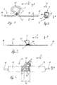
- Fig. 1
- eine Seitenansicht eines Führungskanals,
- Fig. 2
- einen vergrößerten Querschnitt durch den Führungskanal entsprechend der Schnittlinie II-II in Fig. 1,
- Fig. 3
- die Seitenansicht eines Kabels von vorbestimmter Länge,
- Fig. 4
- eine Draufsicht eines Kabelbaumes,
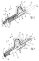
- Fig. 5
- eine perspektivische Darstellung eines weiteren Kabelbaumes,
- Fig. 6
- die perspektivische Darstellung des Kabelbaumes in Fig. 5, jedoch bei maximaler Wirklänge der Umwegstrecke,
- Fig. 7
- die perspektivische Darstellung eines weiteren Kabelbaumes,
- Fig. 8
- die perspektivische Darstellung eines weiteren Kabelbaumes,
- Fig. 9
- die perspektivische Darstellung eines in einem Führungskanal einliegenden Leitungsbündels.
- Fig. 1
- a side view of a guide channel,
- Fig. 2
- 2 shows an enlarged cross section through the guide channel according to section line II-II in FIG. 1,
- Fig. 3
- the side view of a cable of predetermined length,
- Fig. 4
- a plan view of a wire harness,
- Fig. 5
- a perspective view of another wiring harness,
- Fig. 6
- 5 shows the perspective representation of the wiring harness in FIG. 5, but with the maximum effective length of the detour,
- Fig. 7
- the perspective view of another wiring harness,
- Fig. 8
- the perspective view of another wiring harness,
- Fig. 9
- the perspective view of a cable bundle lying in a guide channel.
In Fig. 1 weist ein Führungskanal 1 zwei in einer Leitungslängsrichtung 2 verlaufende Abschnitte und eine zwischen den beiden Abschnitten angeordnete, als Schleife 3 wirksame Umwegstrecke 25 auf. Die Schleife 3 ist in Fig. 1 Ω-förmig ausgestaltet. Die Schleife 3 weist zwei Schleifenenden 4,4' auf. Die beiden Schleifenenden 4,4' stellen die Verbindung zwischen der Schleife 3 und den beiden in Leitungslängsrichtung 2 verlaufenden Abschnitten des Führungskanals 1 her. Die Schleifenenden 4,4' sind aneinandergelegt und durch ein Fixierelement 5 miteinander verbunden.In FIG. 1, a guide channel 1 has two sections running in a
Das Fixierlement 5 in Fig. 1 ist vorzugsweise als stoffschlüssige Verbindung der beiden Schleifenenden 4,4' ausgebildet. Der Stoffschluß wird beispielsweise durch eine Schweißverbindung oder eine Klebung erreicht.The fixing
Der Führungskanal 1 (Fig. 1) weist eine etwa rechteckige Querschnittsform (Fig. 2) mit zwei Kavitäten 6 und einem Einführungsschlitz 7 zum Einlegen eines Leitungsbündels auf. Der Einführungsschlitz 7 verläuft entlang der Leitungslängsrichtung 2 und trennt den gesamten Führungskanal 1 an seiner Mantelfläche auf. Im Bereich des Fixierelements 5 befindet sich der Einführungsschlitz 7 an den in Leitungslängsrichtung 2 einander abgewandten Bereichen der Mantelfläche des Führungskanals 1.The guide channel 1 (FIG. 1) has an approximately rectangular cross-sectional shape (FIG. 2) with two cavities 6 and an insertion slot 7 for inserting a cable bundle. The insertion slot 7 runs along the
Die Kavitäten 6 sind parallel zur Leitungslängsrichtung 2 übereinander in einer zur Leitungslängsrichtung 2 senkrecht stehenden Höhenrichtung 8 angeordnet. Die dem Einführungsschlitz 7 in Höhenrichtung 8 näher angeordnete Kavität 6 weist einen rechteckigen Querschnitt auf. Dieser Querschnitt ist erheblich kleiner als der etwa quadratische Querschnitt der zweiten, vom Einführungsschlitz 7 in Höhenrichtung 8 entfernter angeordneten Kavität 6. Zwischen den beiden Kavitäten 6 sind zwei in einer zur Leitungslängsrichtung 2 und Höhenrichtung 8 senkrecht angeordneten Querrichtung 9 zwei Trennstege 10,10' an die sich gegenüberliegenden Innenwände des Führungskanals 1 angeformt. Mittels der Trennstege 10,10' sollen die Leitungsbündel in der jeweils zugeordneten Kavität 6 sicher verbleiben. Die Trennstege 10,10' sind in Querrichtung 9 derart ausgedehnt, daß zwischen ihnen ein Abstand verbleibt. Er hat die selbe Funktion wie der Einführungsschlitz 7. Der Querschnitt des Führungskanals 1 ist hinsichtlich einer parallel zur Höhenrichtung 8 verlaufenden und den Einführungsschlitz 7 durchdringenden Symmetrieachse achsensymmetrisch.The cavities 6 are arranged one above the other parallel to the
Der Führungskanal 1 besteht wenigstens im Bereich der Schleife 3 aus einem flexiblen Werkstoff, z.B. aus einem Kunststoff. Der flexible Werkstoff kann auch zur erleichterten Einlage des Leitungsbündels durch den Einführungsschlitz 7 in die Kavitäten 6 dienen.The guide channel 1 consists at least in the area of the
Das Fixierelement 5 kann einteiliger Bestandteil des Führungskanalwerkstoffes sein. Das Fixierelement 5 wird dann beispielsweise durch Urformgebung bei der Herstellung des Führungskanals gefertigt.The fixing
In Fig. 3 ist ein einzelnes Kabel 11 mit der Umwegstrecke 25 versehen. Die Umwegstrecke 25 ist zwischen zwei in Leitungslängsrichtung 2 verlaufenden Abschnitten des Kabels 11 angeordnet. Sie ist in Fig. 3 im wesentlichen analog der Umwegstrecke 25 in Fig. 1 als Schleife 3 ausgebildet. Die Fixierung der beiden Schleifenenden 4,4' erfolgt mittels einer separaten Bandage 12. Die Bandage 12 ist in Leitungslängsrichtung 2 um die Schleifenenden 4,4' herumgewickelt und fixiert letztere aneinander.In Fig. 3, a
Bei einem Kabelbaum 13 gemäß Fig. 4 sind die einzelnen Kabel 11 von einer gemeinsamen Umhüllung 14 umgeben. Zwischen zwei Bereichen mit der Umhüllung 14 ist die Umwegstrecke 25 der Kabel 11 als Schleife 3 angeordnet. Im Bereich der Schleife 3 liegen die Kabel 11 ohne Umhüllung 14 frei.4, the
Die Schleife 3 in Fig. 4 ist etwa in analoger Weise wie in Fig. 1 und Fig. 3 ausgebildet. Der Abstand der beiden Schleifenenden 4,4' in Leitungslängsrichtung 2 betrachtet ist jedoch in Fig. 4 erheblich größer als in Fig. 1 und Fig. 3. Dieser Abstand entspricht der Wirklänge 15 der Umwegstrecke.
Die beiden Schleifenenden 4,4' sind im Abstand der Wirklänge 15 durch zwei Fixierstege 16 zueinander fixiert.The
The two loop ends 4, 4 'are fixed to one another at a distance of the
Die beiden Fixierstege 16 verbinden die beiden Umhüllungen 14 miteinander. Die Fixierstege 16 verlaufen parallel zueinander in Leitungslängsrichtung 2 und sind einstückig an den sich gegenüberliegenden Stirnflächen der Umhüllungen 14 angeformt. Hierbei sind die Fixierstege 16 in Querrichtung 9 betrachtet in den Randbereichen der Umhüllungen 14 an letztere angeformt.The two fixing
Die Fixierstege 16 haben eine rechteckige, stabähnliche Außenkontur. In Leitungslängsrichtung 2 betrachtet enthalten sie jeweils in ihrem mittleren Bereich eine Solltrennstelle 17, z.B. eine Einkerbung. Zur Änderung der Wirklänge 15 wird die Solltrennstelle 17 z.B. durchbrochen oder durch einen einfachen Schnitt durchtrennt.The fixing
Die Schleifenenden 4,4' tangieren eine Längsachse 18. Die Längsachse 18 verläuft parallel zur Leitungslängsrichtung 2 und durchdringt den Kabelbaum 13 im Zentrum seines Querschnitts. Die durch die Leitungslängsrichtung 2 und die Höhenrichtung 8 gebildete Schleifenebene ist in Fig. 1 und Fig. 3 ebenso wie in Fig. 4 in Höhenrichtung 8 betrachtet neben der Längsachse 18 angeordnet.The loop ends 4, 4 'tangent to a
Sofern hinreichende Elastizität des Werkstoffes der Umhüllung 14 zur Bildung der Schleife 3 (Fig. 4) gewährleistet ist, ist es auch denkbar, die Kabelabschnitte im Schleifenbereich mit dem Umhüllungswerkstoff zu umgeben.If sufficient elasticity of the material of the
In Fig. 5 bis Fig. 8 sind weitere Ausführungsformen eines Kabelbaumes 13 dargestellt.5 to 8 show further embodiments of a
In Fig. 5 ist ein Leitungsbündel 19 in Leitungslängsrichtung 2 betrachtet in zwei Abschnitten von der Umhüllung 14 umgeben. Zwischen den beiden Abschnitten mit der Umhüllung 14 befindet sich die Umwegstrecke 25 des Kabelbaums 13. Sie ist durch eine sinusartige Welle gebildet. Die Umwegstrecke 25 enthält insgesamt fünf als Schleifen 3 wirksame Halbwellen. Die Schleifenebene ist durch die Leitungslängsrichtung 2 und die Höhenrichtung 8 gebildet. Die Schleifenebene wird von der Längsachse 18 in Höhenrichtung 8 betrachtet halbiert. Schleifenanfang und Schleifenende jeder einzelnen Schleife 3 werden von der Längsachse 18 geschnitten.In FIG. 5, a
Im Bereich der Wirklänge 15 ist das Leitungsbündel 19 von einem flexiblen Hüllteil 20 umgeben, z.B. mit einem elastischen Kunststoff umspritzt. Das Hüllteil 20 hat in Leitungslängsrichtung 2 betrachtet einen rechteckigen Querschnitt. Dieser Querschnitt ist im Bereich der Schleifenenden 4,4' zentral um die Längsachse 18 angeordnet und wesentlich kleiner als der ebenfalls in Leitungslängsrichtung 2 betrachtet rechteckige Querschnitt der Umhüllung 14. Die Umhüllungen 14 bewirken eine Formstabilität des Kabelbaums 13 in den Bereichen außerhalb der Wirklänge 15.In the area of the
Zur Ausgestaltung und Anordnung der Fixierstege 16 gelten die Ausführungen in Fig. 4. Die Fixierstege 16 weisen in Leitungslängsrichtung 2 betrachtet einen rechteckigen Querschnitt auf. In Höhenrichtung 8 gesehen sind sie in den unteren Eckbereichen der einander zugewandten rechteckigen Stirnflächen der Umhüllungen 14 angeordnet und dort angeformt. Es ist auch denkbar, daß die Fixierstege 16 länger als die Wirklänge 15 sind. In diesem Fall sind die in Fig. 5 nicht sichtbaren Enden der Fixierstege 16 von den Umhüllungen 14 umgeben.The explanations in FIG. 4 apply to the design and arrangement of the fixing
In Fig. 6 ist der in Fig. 5 dargestellte Kabelbaum 13 erkennbar. Die Fixierstege 16 sind jedoch durchtrennt. Die mit dem Hüllteil 20 versehene Umwegstrecke des Kabelbaums 13 ist in Leitungslängsrichtung 2 völlig gestreckt, so daß die maximale Wirklänge 15 der Umwegstrecke 25 erreicht ist.The
Der Kabelbaum 13 in der Fig. 7 enthält wie in Fig. 5 und Fig. 6 zwei Bereiche mit jeweils einer Umhüllung 14. Die Ausgestaltung und Anordnung der Umhüllungen 14 und der Fixierstege 16 sowie ihre gegenseitigen Verbindungen entsprechen im wesentlichen der Beschreibung in Fig. 5 und Fig. 6. Zwischen den beiden Bereichen mit den Umhüllungen 14 ist das Leitungsbündel 19 von dem flexiblen Hüllteil 20 umgeben. Das Hüllteil 20 hat in Leitungslängsrichtung 2 betrachtet eine rechteckige Außenkontur. Im Bereich der Schleifenenden 4,4' ist das Hüllteil 20 analog der Beschreibung in Fig. 5 an den Umhüllungen 14 angeordnet.As in FIGS. 5 and 6, the
Entlang der Wirklänge 15 enthält die Umwegstrecke 25 des Kabelbaums 13 zwei Schleifen 3. Sie liegen in Höhenrichtung 8 aufeinander. Damit eine derartige Lagefixierung der Schleifen 3 gewährleistet ist, sind der Anfang und das Ende jeweils einer Schleife 3 - gesehen in Höhenrichtung 8 - durch das Fixierelement 5 (Fig. 1) verbunden. Die Schleifen 3 können auch durch ein diese in Höhenrichtung 8 und Querrichtung 9 umfassendes Halteband in ihrer Auslenkstellung gehalten sein.
Diese Ausgestaltung der Umwegstrecke 25 bewirkt in Leitungslängsrichtung 2 gesehen einen nur unwesentlich vergrößerten Querschnitt gegenüber dem entsprechenden Querschnitt des Kabelbaums 13 im Bereich der Umhüllungen 14.
Diese Ausgestaltung der Umwegstrecke 25 läßt sich bevorzugt bei Flachbandkabeln anwenden. Auch bei großen Längenänderungen zwischen zwei verschiedenen Längenversionen ist diese Anordnung der Umwegstrecke 25 günstig.Along the
This configuration of the
This configuration of the
Enthält der Kabelbaum 13 eine Vielzahl von Schleifen 3 gemäß Fig. 7, so ist eine flexible Anpassung der Wirklänge 15 an vorher nicht genau bekannte Längenänderungen möglich. Zu diesem Zweck wird nur eine der notwendigen Wirklängenänderung entsprechende Anzahl von Fixierelementen gelöst.If the
In Fig. 8 ist die Umwegstrecke 25 des Kabelbaums durch eine Schleife 3 gebildet. Die Anordnung und Ausgestaltung der Schleife 3 entspricht im wesentlichen derjenigen in Fig. 4. Die Ausgestaltung der Fixierstege 16 und deren Anordnung an den Umhüllungen 14 entsprechen den Ausführungen in Fig. 5 bis Fig.7.In Fig. 8, the
Die Umhüllungen 14 weisen in Leitungslängsrichtung 2 gesehen einen trapezförmigen Querschnitt auf. Eine der beiden Umhüllungen 14 ist an ihren sämtlichen in Leitungslängsrichtung 2 verlaufenden Oberflächen mit senkrecht zu dieser Richtung angeordneten Einschnitten 21 versehen. Jeweils zwei in Querrichtung 9 und zwei in Höhenrichtung 8 verlaufende Einschnitte 21 bilden einen geschlossenen Umlauf um die Längsachse 18. Der geschlossene Einschnittsumlauf bewirkt an dieser Stelle eine gegenüber der übrigen Umhüllung verkleinerte trapezförmige Außenkontur der Umhüllung 14. Die Einschnittsumläufe sind in gleichmäßigem Abstand in Leitungslängsrichtung 2 verteilt. Die Abstände selbst sind durch radial um das Leitungsbündel 19 vorstehende Rippen 26 gebildet, deren Querschnitt demjenigen der nicht mit den Einschnitten 21 versehenen Umhüllung 14 entspricht. Die Umhüllung 14 mit den Rippen 26 hat dadurch das Aussehen einer in Leitungslängsrichtung 2 auseinandergezogenen Ziehharmonika.The
In Fig. 8 ist erkennbar, daß die einzelnen Kabel 11 durch ein sie umgebendes Halteband 22 als Leitungsbündel 19 zusammengehalten sind. Das Halteband 22 wiederum ist von den Umhüllungen 14 umgeben.In Fig. 8 it can be seen that the
Die mit den Rippen 26 versehene Umhüllung 14 hat den Vorteil, daß im Kabelbaum 13 einliegende Kabel 11 oder Leitungsbündel 19 nicht in Höhenrichtung 8 nach außen gelangen und der Kabelbaum 13 im Gegensatz zu glatten Oberflächen der Umhüllung 14 besser vor mechanischen Beschädigungen z.B. durch Abscheuern der Oberfläche der Umhüllung 14 geschützt ist. Damit sind auch die Kabel 11 oder das Leitungsbündel 19 vor Beschädigungen geschützt. Im Falle von elektrischen Leitungen wird eine Kurzschlußgefahr vermieden.The
Die Einschnitte 21 bewirken, daß die ansonsten formstabile Umhüllung 14 bis zu einem bestimmten Grad biegbar ist.
Auch können die Einschnitte 21 dazu verwendet werden, den Kabelbaum 13 in eine Haltevorrichtung einzurasten oder auf andere Weise ortsfest zu fixieren.The
The
Fig. 9 läßt einen Führungskanal 1 erkennen, der mit dem Leitungsbündel 19 bestückt ist. Die Umwegstrecke des Leitungsbündels 19 ist analog den Ausführungen in Fig. 8 als Schleife 3 angeordnet und ausgestaltet.
Im Bereich der Schleife 3 sind die einzelnen Kabel 11 des Leitungsbündels 19 von dem Halteband 22 umhüllt. Die Umhüllung der Kabel 11 durch das Halteband 22 ersteckt sich etwas über die Schleifenenden 4,4' in Leitungslängsrichtung 2 hinaus. In dem größten Bereich der in Leitungslängsrichtung 2 verlaufenden Abschnitte des Leitungsbündels 19 übernimmt jedoch der Führungskanal 1 die Bündelungs- und Hüllfunktion für die Kabel 11.Fig. 9 shows a guide channel 1, which is equipped with the
In the area of the
Der Führungskanal 1 weist in Leitungslängsrichtung 2 gesehen einen U-förmigen Querschnitt auf. Entsprechend den U-Schenkeln enthält der Führungskanal 1 zwei parallel zueinander angeordnete und in Leitungslängsrichtung 2 verlaufende Kanalseitenwände 23. Sie liegen in einer durch die Leitungslängsrichtung 2 und die Höhenrichtung 8 gebildeten Ebene ein. Die sich in Querrichtung 9 gegenüberliegenden Kanalseitenwände 23 sind durch einen dem U-Grund entsprechenden Kanalboden 24 miteinander verbunden. Kanalseitenwände 23 und Kanalboden 24 sind senkrecht zueinander angeordnet.
Im Bereich der Schleife 3 sind die Kanalseitenwände 23 auf die Abmessungen der Fixierstege 16 reduziert. In Querrichtung 9 gesehen erhält der Führungskanal 1 deshalb zwei sich gegenüberliegende rechteckige Einschnitte. Die Fixierstege 16 sind einstückiger Bestandteil der Kanalseitenwände 23 und verbinden die sich in Leitungslängsrichtung 2 gegenüberliegenden, dem Kanalboden 24 am nächsten angeordneten Bereiche der Kanalseitenwände 23 miteinander. Damit die beiden Führungskanalabschnitte nach dem Durchtrennen der Fixierstege 16 in Leitungslängsrichtung 2 verschoben werden können, ist im Bereich der Wirklänge 15 kein Kanalboden 24 vorhanden.The guide channel 1 has a U-shaped cross section as seen in the
In the area of the
Jeder Fixiersteg 16 ist durch zwei Solltrennstellen 17 in zwei etwa gleichlange Teile getrennt. Die beiden Solltrennstellen 17 jeweils eines Fixiersteges 16 sind als V-förmige Einschnitte in die in Höhenrichtung 8 gegenüberliegenden Oberflächen des Fixiersteges 16 ausgebildet. Hierbei sind die Öffnungen der in Querrichtung 9 gesehen V-förmigen Solltrennstellen 17 einander abgewandt.Each fixing
Die in den Figuren dargestellten Führungskanäle 1 bzw. Kabelbäume 13 weisen jeweils eine in Leitungslängsrichtung 2 ausgerichtete, vorbestimmte, der Normalversion des Fahrzeugtyps angepaßte Länge auf.The guide channels 1 or cable harnesses 13 shown in the figures each have a predetermined length which is oriented in the
Um die Wirklänge 15 des Erfindungsgegenstandes zu verändern, werden das Fixierelement 5, die Bandage 12 und/oder die Solltrennstellen 17 der Fixierstege 16 durchtrennt. Die Lösung des Fixierelementes 5 erfolgt z.B. durch einen Schnitt, wodurch die Hüll- und Schutzfunktion des Führungskanals 1 (Fig. 1) oder des Hüllteils 20 (Fig. 7) jedoch nicht beeinträchtigt ist.
Das Fixierelement 5 kann z.B. auch nach Art einer aufreißbaren Kunststoffflasche ausgebildet sein.
Die Fixierstege 16 sind vorzugsweise starr ausgebildet, damit diese im Bereich der Solltrennstelle 17 auch durch einen einfachen Bruch durchtrennt werden können.In order to change the
The fixing
The fixing
Nach Lösung der Fixierungen des Führungskanals 1 bzw. des Kabelbaums 13 läßt sich die Wirklänge 15 vergrößern und das Leitungsbündel 19 auf eine der Langversion angepaßte Länge in Leitungslängsrichtung 2 auseinanderziehen. Hierbei werden die Schleifen 3 zumindest teilweise aufgehoben.After loosening the fixations of the guide channel 1 or the
- 11
- FührungskanalGuide channel
- 22nd
- LeitungslängsrichtungLongitudinal line
- 33rd
- Schleifeloop
- 44th
- SchleifenendeLoop end
- 4'4 '
- SchleifenendeLoop end
- 55
- FixierelementFixing element
- 66
- Kavitätcavity
- 77
- EinführungsschlitzInsertion slot
- 88th
- HöhenrichtungHeight direction
- 99
- QuerrichtungCross direction
- 1010th
- TrennstegSeparator
- 10'10 '
- TrennstegSeparator
- 1111
- Kabelelectric wire
- 1212th
- Bandagebandage
- 1313
- KabelbaumWiring harness
- 1414
- UmhüllungWrapping
- 1515
- WirklängeEffective lengths
- 1616
- FixierstegFixing bar
- 1717th
- SolltrennstelleSeparation point
- 1818th
- LängsachseLongitudinal axis
- 1919th
- LeitungsbündelTrunk group
- 2020th
- HüllteilEnvelope part
- 2121
- Einschnittincision
- 2222
- HaltebandTether
- 2323
- KanalseitenwandCanal side wall
- 2424th
- KanalbodenCanal floor
- 2525th
- UmwegstreckeDetour route
- 2626
- Ripperib
Claims (21)
- A cable harness (13) containing supply lines (11) in a bundled form or a guide channel (1) intended for receiving the supply lines (11) - both designated briefly below as "line holders" -,with a deviation path (25) of the line bundle (11, 19) arranged in the bundling zone,
characterized by
a fixing element (5, 12, 16) receiving the deviation path (25) in its functional state, by means of the irreversible release of which element the line bundle (11, 19) can be lengthened in its effective length (15) into a long version, in particular for motor vehicles, without affecting the line functions. - A line holder according to claim 1,
characterized in that
the deviation path (25) has the shape of a loop (3) lying at least partly outside the longitudinal axis (18) of the line holder (1, 11). - A line holder according to claim 2,
characterized in that
the plane of the loop lies next to the longitudinal axis (18) of the line holder (1, 11). - A line holder according to claim 2,
characterized in that
the longitudinal axis (18) extends in the plane of the loop and intersects the deviation path (25) in this arrangement. - A line holder according to one of claims 2 to 4,
characterized by
a Ω-shape of the loop (3). - A line holder according to one of claims 1 to 3,
characterized in that
the deviation path (25) contains several loops (3) disposed in series in the longitudinal line direction (2). - A line holder according to claim 4,
characterized in that
the deviation path (25) is formed by a sinusoidal wave. - A line holder according to claim 7,
characterized in that
the wave extends in the longitudinal line direction (2). - A line holder according to one or more of the preceding claims,
characterized in that
the fixing element (5, 12, 16) joins the ends (4, 4') of the deviation path (25) to each other in a path that has been shortened as compared with its length. - A line holder according to claim 9,
characterized in that
the fixing element (5, 12, 16) joins the ends (4, 4') of the deviation path (25) to each other in an adjacent position. - A line holder according to claim 10,
characterized in that
the fixing element (5, 12, 16) is a bandage, a tape or a clip. - A line holder according to one or more of the preceding claims,
characterized in that
the fixing element (5, 12, 16) is a material bond between the supply lines (11), their insulations or the zones of the line holder (1, 13), disposed in the zone of the ends (4, 4') of the deviation path (25). - A line holder according to claim 12,
characterized in that
the material is produced by a welded joint. - A line holder according to claim 9,
characterized in that
the fixing element is a connecting element (16) inserted with its ends in the line holder (1, 13). - A line holder according to claim 9,
characterized in that
the fixing element (5, 12, 16) consists of the material of the line holder (1, 13), and is integrally formed with the latter, being in particular injection-moulded from a synthetic material. - A line holder according to claim 14 or 15,
characterized in that
the fixing element integrally formed from the material of the line holder (1, 13) contains the connecting element (16) as a stiffening insert. - A line holder according to one or more of the preceding claims,
characterized in that
the fixing element (5, 12, 16) contains a predetermined breaking point (17). - A line holder according to one or more of the preceding claims,
characterized in that
at least one fixing element (5, 12, 16) is arranged on the line holder (1, 13), extending parallel to the longitudinal axis (18). - A line holder according to one or more of the preceding claims,
characterized in that
the guide channel (1) has a U-shaped cross-section outside the deviation path (25); and that the zones of the guide channel (1) adjoining the deviation path (25) are joined to each other by two fixing elements (16), in which arrangement one fixing element each connects the angular zones of the U-shape of the guide channel (1) to each other. - A line holder according to one or more of the preceding claims,
characterized in that
the guide channel (1) is a tubular conduit with an insertion slit (7) passing through its cover and extending approximately parallel to the longitudinal axis (18) for the insertion of the line bundle (11, 19). - A line holder according to one or more of the preceding claims,
characterized in that
a sheath (14) surrounding the line bundle (11, 19) has, in its zone adjoining the deviation path (25), radially projecting projections, in particular ribs (26) that are effective over the whole circumference as a mechanical protection against damage.
Applications Claiming Priority (4)
| Application Number | Priority Date | Filing Date | Title |
|---|---|---|---|
| DE9112525 | 1991-10-04 | ||
| DE9112525U | 1991-10-04 | ||
| DE9200909U | 1992-01-27 | ||
| DE9200909U DE9200909U1 (en) | 1992-01-27 | 1992-01-27 |
Publications (3)
| Publication Number | Publication Date |
|---|---|
| EP0535712A2 EP0535712A2 (en) | 1993-04-07 |
| EP0535712A3 EP0535712A3 (en) | 1993-06-30 |
| EP0535712B1 true EP0535712B1 (en) | 1995-05-10 |
Family
ID=25958730
Family Applications (1)
| Application Number | Title | Priority Date | Filing Date |
|---|---|---|---|
| EP92116985A Revoked EP0535712B1 (en) | 1991-10-04 | 1992-10-05 | Wire harness or wire channel, particularly for a motor vehicle |
Country Status (3)
| Country | Link |
|---|---|
| EP (1) | EP0535712B1 (en) |
| DE (1) | DE59202139D1 (en) |
| ES (1) | ES2073224T3 (en) |
Families Citing this family (12)
| Publication number | Priority date | Publication date | Assignee | Title |
|---|---|---|---|---|
| JP3293744B2 (en) * | 1996-07-15 | 2002-06-17 | 矢崎総業株式会社 | Assembly structure of door circuit |
| US6120327A (en) * | 1997-07-22 | 2000-09-19 | Lear Automotive Dearborn, Inc. | Foam wire harness with shape memory |
| EP0900698B1 (en) * | 1997-09-04 | 2003-04-16 | Delphi Automotive Systems Deutschland GmbH | Ignition system protection system |
| US6610929B1 (en) * | 1999-01-12 | 2003-08-26 | Autonetworks Technologies, Ltd. | Wire harness for removing from a vehicle |
| AT501303B8 (en) * | 2004-09-30 | 2007-02-15 | Siemens Transportation Systems | METHOD AND DEVICE FOR PREPARING A JUMPING HOSE CABLE |
| EP1957318A1 (en) * | 2005-11-28 | 2008-08-20 | Renault Trucks | A holding arrangement for a wire harness |
| JP5074757B2 (en) * | 2006-12-19 | 2012-11-14 | 矢崎総業株式会社 | Power feeding device and harness wiring structure using the same |
| FR2929900B1 (en) * | 2008-04-09 | 2010-06-04 | Peugeot Citroen Automobiles Sa | GUTTER FOR CABLE AND MOTOR VEHICLE COMPRISING SUCH A GUTTER |
| JP5654363B2 (en) | 2011-01-20 | 2015-01-14 | 矢崎総業株式会社 | Conductive path structure and wire harness |
| JP6346844B2 (en) * | 2014-11-04 | 2018-06-20 | 矢崎総業株式会社 | Conductive path connection member |
| CN106524024B (en) * | 2015-09-11 | 2019-07-12 | 本田技研工业(中国)投资有限公司 | Car light wiring mounting structure |
| DE102018213518A1 (en) * | 2018-08-10 | 2020-02-13 | Bayerische Motoren Werke Aktiengesellschaft | Line arrangement, component arrangement and working device |
Family Cites Families (2)
| Publication number | Priority date | Publication date | Assignee | Title |
|---|---|---|---|---|
| FR1152317A (en) * | 1956-06-13 | 1958-02-14 | Expandable electric conductor | |
| FR2611999B1 (en) * | 1987-03-05 | 1989-06-30 | Peugeot | DEVICE FOR ELECTRICALLY CONNECTING BETWEEN TWO BEAMS OF CONDUCTING WIRES AND MOTOR VEHICLE EQUIPPED WITH THIS DEVICE |
-
1992
- 1992-10-05 DE DE59202139T patent/DE59202139D1/en not_active Expired - Lifetime
- 1992-10-05 ES ES92116985T patent/ES2073224T3/en not_active Expired - Lifetime
- 1992-10-05 EP EP92116985A patent/EP0535712B1/en not_active Revoked
Also Published As
| Publication number | Publication date |
|---|---|
| ES2073224T3 (en) | 1995-08-01 |
| DE59202139D1 (en) | 1995-06-14 |
| EP0535712A3 (en) | 1993-06-30 |
| EP0535712A2 (en) | 1993-04-07 |
Similar Documents
| Publication | Publication Date | Title |
|---|---|---|
| DE102007040812B4 (en) | Folding type cable protection and routing device | |
| DE60214024T2 (en) | FASTENING DEVICE FOR CABLE TREE | |
| EP0268869B1 (en) | Synthetic protective tubing device for conduits | |
| EP0535712B1 (en) | Wire harness or wire channel, particularly for a motor vehicle | |
| DE3819549A1 (en) | PROTECTIVE DEVICE FOR BUNDLE STRAND | |
| DE102018217839A1 (en) | Harness protection device and method of manufacturing the wiring harness | |
| DE112018005871T5 (en) | Cable harness support element, cable harness provided with support element and support structure for a cable harness provided with support element | |
| DE60107000T3 (en) | Apparatus for carrying and guiding a bundle of electrical conductors which permit following movements of a front seat of a motor vehicle | |
| DE102007041663A1 (en) | Device for guiding lines, hoses or the like | |
| DE19921351C2 (en) | Harness mounting assembly | |
| DE102005053028B4 (en) | Power supply apparatus | |
| DE102005046194B4 (en) | Cable duct with channel segments | |
| DE3437448A1 (en) | DEVICE FOR PRODUCING CABLE-SPLICE CONNECTIONS, IN PARTICULAR FOR LIGHT-GUIDE CABLES | |
| DE112018007293T5 (en) | Harness protector and harness laying structure using the same | |
| DE102019214725A1 (en) | WIRING HARNESS | |
| DE3545517C2 (en) | ||
| DE102004005307B3 (en) | Closure arrangement for slotted pipes, especially corrugated pipes for protective casings for electric cables in motor vehicles is double-T support with bridge and upper and lower elements whose distance corresponds to slot dimensions | |
| DE102016112758B4 (en) | HOLDING PART AND METHOD FOR ATTACHING ELECTRICAL LINES AND LINE ARRANGEMENT IN A VEHICLE | |
| DE19606643C2 (en) | Fastening device for cable harnesses and use of the fastening device | |
| DE102017209969A1 (en) | harness | |
| DE102007014064B4 (en) | Device for the protected arrangement of optical fibers | |
| DE102021107321A1 (en) | Guard and wiring harness | |
| DE102004005310B4 (en) | Split cylinder tube as protective cover for electrical cables in motor vehicles has projections on opposite edges of slit held together by separate gripper | |
| DE102021118101B4 (en) | HOLDING PART | |
| DE102018201175A1 (en) | Cable fixing device and motor vehicle |
Legal Events
| Date | Code | Title | Description |
|---|---|---|---|
| PUAI | Public reference made under article 153(3) epc to a published international application that has entered the european phase |
Free format text: ORIGINAL CODE: 0009012 |
|
| AK | Designated contracting states |
Kind code of ref document: A2 Designated state(s): BE DE DK ES FR GB GR IE IT LU NL PT |
|
| PUAL | Search report despatched |
Free format text: ORIGINAL CODE: 0009013 |
|
| AK | Designated contracting states |
Kind code of ref document: A3 Designated state(s): BE DE DK ES FR GB GR IE IT LU NL PT |
|
| 17P | Request for examination filed |
Effective date: 19930608 |
|
| 17Q | First examination report despatched |
Effective date: 19941013 |
|
| GRAA | (expected) grant |
Free format text: ORIGINAL CODE: 0009210 |
|
| AK | Designated contracting states |
Kind code of ref document: B1 Designated state(s): BE DE DK ES FR GB GR IE IT LU NL PT |
|
| PG25 | Lapsed in a contracting state [announced via postgrant information from national office to epo] |
Ref country code: NL Free format text: LAPSE BECAUSE OF FAILURE TO SUBMIT A TRANSLATION OF THE DESCRIPTION OR TO PAY THE FEE WITHIN THE PRESCRIBED TIME-LIMIT Effective date: 19950510 Ref country code: DK Effective date: 19950510 Ref country code: BE Effective date: 19950510 |
|
| REG | Reference to a national code |
Ref country code: IE Ref legal event code: FG4D Free format text: 63750 |
|
| REF | Corresponds to: |
Ref document number: 59202139 Country of ref document: DE Date of ref document: 19950614 |
|
| GBT | Gb: translation of ep patent filed (gb section 77(6)(a)/1977) |
Effective date: 19950605 |
|
| PGFP | Annual fee paid to national office [announced via postgrant information from national office to epo] |
Ref country code: DE Payment date: 19950801 Year of fee payment: 4 |
|
| REG | Reference to a national code |
Ref country code: ES Ref legal event code: FG2A Ref document number: 2073224 Country of ref document: ES Kind code of ref document: T3 |
|
| ITF | It: translation for a ep patent filed |
Owner name: UFFICIO BREVETTI RICCARDI & C. |
|
| PG25 | Lapsed in a contracting state [announced via postgrant information from national office to epo] |
Ref country code: PT Effective date: 19950810 |
|
| ET | Fr: translation filed | ||
| PG25 | Lapsed in a contracting state [announced via postgrant information from national office to epo] |
Ref country code: GR Free format text: LAPSE BECAUSE OF FAILURE TO SUBMIT A TRANSLATION OF THE DESCRIPTION OR TO PAY THE FEE WITHIN THE PRESCRIBED TIME-LIMIT Effective date: 19950811 |
|
| PGFP | Annual fee paid to national office [announced via postgrant information from national office to epo] |
Ref country code: FR Payment date: 19950817 Year of fee payment: 4 |
|
| PGFP | Annual fee paid to national office [announced via postgrant information from national office to epo] |
Ref country code: ES Payment date: 19951023 Year of fee payment: 4 |
|
| PG25 | Lapsed in a contracting state [announced via postgrant information from national office to epo] |
Ref country code: LU Free format text: LAPSE BECAUSE OF NON-PAYMENT OF DUE FEES Effective date: 19951031 |
|
| NLV1 | Nl: lapsed or annulled due to failure to fulfill the requirements of art. 29p and 29m of the patents act | ||
| PG25 | Lapsed in a contracting state [announced via postgrant information from national office to epo] |
Ref country code: IE Free format text: LAPSE BECAUSE OF NON-PAYMENT OF DUE FEES Effective date: 19951115 |
|
| REG | Reference to a national code |
Ref country code: IE Ref legal event code: FD4D Ref document number: 63750 Country of ref document: IE |
|
| PLBI | Opposition filed |
Free format text: ORIGINAL CODE: 0009260 |
|
| PLBF | Reply of patent proprietor to notice(s) of opposition |
Free format text: ORIGINAL CODE: EPIDOS OBSO |
|
| 26 | Opposition filed |
Opponent name: BAYERISCHE MOTOREN WERKE AKTIENGESELLSCHAFT Effective date: 19960131 |
|
| PLBF | Reply of patent proprietor to notice(s) of opposition |
Free format text: ORIGINAL CODE: EPIDOS OBSO |
|
| PG25 | Lapsed in a contracting state [announced via postgrant information from national office to epo] |
Ref country code: DE Effective date: 19960921 |
|
| PLBF | Reply of patent proprietor to notice(s) of opposition |
Free format text: ORIGINAL CODE: EPIDOS OBSO |
|
| RDAH | Patent revoked |
Free format text: ORIGINAL CODE: EPIDOS REVO |
|
| RDAG | Patent revoked |
Free format text: ORIGINAL CODE: 0009271 |
|
| STAA | Information on the status of an ep patent application or granted ep patent |
Free format text: STATUS: PATENT REVOKED |
|
| GBPR | Gb: patent revoked under art. 102 of the ep convention designating the uk as contracting state |
Free format text: 961007 |
|
| 27W | Patent revoked |
Effective date: 19961007 |