EP0535712B1 - Faisceau de câble ou puits à câbles, particulièrement pour une voiture automobile - Google Patents
Faisceau de câble ou puits à câbles, particulièrement pour une voiture automobile Download PDFInfo
- Publication number
- EP0535712B1 EP0535712B1 EP92116985A EP92116985A EP0535712B1 EP 0535712 B1 EP0535712 B1 EP 0535712B1 EP 92116985 A EP92116985 A EP 92116985A EP 92116985 A EP92116985 A EP 92116985A EP 0535712 B1 EP0535712 B1 EP 0535712B1
- Authority
- EP
- European Patent Office
- Prior art keywords
- line
- line holder
- holder according
- fixing element
- bundle
- Prior art date
- Legal status (The legal status is an assumption and is not a legal conclusion. Google has not performed a legal analysis and makes no representation as to the accuracy of the status listed.)
- Revoked
Links
Images

Classifications
-
- B—PERFORMING OPERATIONS; TRANSPORTING
- B60—VEHICLES IN GENERAL
- B60R—VEHICLES, VEHICLE FITTINGS, OR VEHICLE PARTS, NOT OTHERWISE PROVIDED FOR
- B60R16/00—Electric or fluid circuits specially adapted for vehicles and not otherwise provided for; Arrangement of elements of electric or fluid circuits specially adapted for vehicles and not otherwise provided for
- B60R16/02—Electric or fluid circuits specially adapted for vehicles and not otherwise provided for; Arrangement of elements of electric or fluid circuits specially adapted for vehicles and not otherwise provided for electric constitutive elements
- B60R16/0207—Wire harnesses
- B60R16/0215—Protecting, fastening and routing means therefor
Definitions
- the invention relates to a cable harness or a cable routing, in particular for motor vehicles, with the features of the preamble of claim 1.
- Such cable harnesses or guide channels - both referred to below as "cable holders” for short - are known.
- line holders a large number of lines are at least partially encased by a molded body in their longitudinal extent.
- the shaped body consists in certain areas of a plastic with high elasticity.
- Such a configuration of the molded body makes it possible to lay the cable bundle more easily and to adapt it to non-straight line paths.
- Line bundles of this type are known, for example, from EP-0 288 752 or EP-0 418 882.
- the term “trunk group” here stands for a single line or for several lines.
- the lines include cables, for example electrical cables or optical fibers. Hose-like lines such as windscreen washer water lines, hydraulic or pneumatic lines or the like are also meant. Lines for the transmission of mechanical energy, for example Bowden cables, are also conceivable.
- the term “motor vehicles” stands for motor vehicles and trucks.
- a line bundle with the features of the preamble of claim 1 is already known, the effective length of which can be extended elastically.
- the bundled supply lines are laid in a zigzag fashion to the longitudinal direction of the bundle and the zigzag laying is maintained by a tension spring running in the longitudinal direction of the bundle.
- the tension spring can be stretched, with the result that the zigzag laying of the supply lines can be converted into a stretched or extended position of a length which can be - until the bundle is fully stretched is proportional to the tensile or stretching force.
- This arrangement serves for an elastic adaptability of the effective length of the cable bundle to the change in position of an electrical device or the like supplied by the cable bundle, e.g. of a phone.
- an electrical device or the like supplied by the cable bundle e.g. of a phone.
- the Nuremberg scissors are used to slightly change the distance between the tablet and the stand so that the tablet can be brought close to the working position for making calls, but can be pushed back into a rest position away from the seat when the phone is not in use.
- an elastic adaptability of the line bundle serving to supply the telephone set to the effective lengths of the line path is advantageous.
- the tension spring enables a stepless and reversible change in the effective length of the cable bundle.
- the resulting mobility of the cable bundle in the longitudinal direction of the bundle contradicts the mechanically stable installation position of the cable bundle required in certain technical areas.
- the tension spring due to its inherent elasticity do not receive the predetermined effective lengths of the cable bundle in their installed position.
- Such cable bundles provided with tension springs are only suitable for technical areas in which the required effective length of the cable bundle cannot be predetermined and in which the effective length must be constantly changeable even in the installed position of the cable bundle.
- the invention is based on the object of designing a line holder containing the line bundle in such a way that the differently long line paths can be equipped with one and the same line bundle.
- the predetermined length of the cable bundle should be adapted to the mounting conditions specified in terms of dimensions for the vehicle type in question.
- the detour route of the line bundle can be advantageously used in the case of curved line route guides.
- the fixing element is also released and the deflection position of the cable bundle of the bending point of the cable routing, for example a cable duct, is adapted accordingly. If the line bundle contains several detours, which are arranged at a distance from one another in the longitudinal direction of the line, an even more flexible adaptation of one and the same line bundle to line paths of different lengths or different bends is possible.
- Claims 2 to 8 relate to preferred embodiments of the detour route. Depending on the application and location, a certain deflection position of the detour route is cheap or necessary.
- a detour route designed according to claim 4 causes an only insignificant increase in the effective cross section of the line holder in the region of Detour route. This ensures a space-saving arrangement of the detour route.
- the detour route according to claim 6 enables particularly large changes in the effective length of the line bundle.
- the shortest effective distance of the detour route and thus the largest change in effective length can be realized in a simple manner.
- Claims 11 to 18 relate to special embodiments of the fixing element. According to claim 11 known fixing elements are proposed which are separable from the line holder as separate parts.
- Claim 12 relates to a particularly simple and inexpensive manufacture of the fixing element. Elaborate connection techniques are avoided.
- Claim 13 relates to a preferred embodiment of the material connection.
- a fixed fixation of the fixing element in the line holder is guaranteed.
- the stability of the fixing element is improved. This avoids displacements or mechanical damage to the fixing element, so that the detour also remains safely in its deflected position.
- a fixing element designed according to claim 15 also ensures good stability of the line holder. Because of the material unit, the cable holder and the fixing element are easy to manufacture. The connection between The cable holder and fixing element is well protected against damage. In addition, complex connection techniques between the fixing element and the line holder are avoided.
- the stability between the line holder and the fixing element is further improved.
- a fixing element designed according to claim 17 enables a simple change in the effective length of the cable bundle. Mechanical damage to the fixing element during the loosening process is also avoided.
- Claim 18 relates to a preferred arrangement of the fixing element.
- the outer contour of the line holder in the area of the detour is therefore essentially retained.
- the fixing element does not require any additional space when laying the cable bundle in a cable route.
- Claims 19 and 20 relate to preferred embodiments of the guide channel for loose insertion of the line bundle.
- Such guide channels are suitable for protected storage and for the transport of cable bundles.
- the guide channels can be easily equipped with the cable bundle.
- the cable bundles can also be exchanged without any problems.
- Claim 21 relates to a preferred embodiment of the cable harness to protect the cable bundle from mechanical damage. In the case of electrical lines, the mechanical protection also reduces the risk of short circuits.
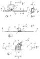
- a guide channel 1 has two sections running in a longitudinal direction 2 of the line and a detour 25, which is arranged between the two sections and acts as a loop 3.
- the loop 3 is ⁇ -shaped in Fig. 1.
- the loop 3 has two loop ends 4, 4 '.
- the two loop ends 4, 4 ' establish the connection between the loop 3 and the two sections of the guide channel 1 running in the longitudinal direction 2 of the line.
- the loop ends 4, 4 ' are placed against one another and connected to one another by a fixing element 5.
- the fixing element 5 in FIG. 1 is preferably designed as a material connection between the two loop ends 4, 4 '.
- the material bond is achieved, for example, by a welded connection or an adhesive.
- the guide channel 1 (FIG. 1) has an approximately rectangular cross-sectional shape (FIG. 2) with two cavities 6 and an insertion slot 7 for inserting a cable bundle.
- the insertion slot 7 runs along the longitudinal direction 2 of the line and separates the entire guide channel 1 on its outer surface. In the area of the fixing element 5, the insertion slot 7 is located on the areas of the lateral surface of the guide channel 1 which face away from one another in the longitudinal direction 2 of the line.
- the cavities 6 are arranged one above the other parallel to the longitudinal line direction 2 in a vertical direction 8 perpendicular to the longitudinal line direction 2.
- the cavity 6, which is arranged closer to the insertion slot 7 in the height direction 8, has a rectangular cross section. This cross section is considerably smaller than the approximately square cross section of the second cavity 6, which is arranged further away from the insertion slot 7 in the vertical direction 8.
- the line bundles are to remain securely in the respectively assigned cavity 6 by means of the separating webs 10, 10 '.
- the dividers 10, 10 ' are extended in the transverse direction 9 in such a way that a distance remains between them. It has the same function like the insertion slot 7.
- the cross section of the guide channel 1 is axisymmetric with respect to an axis of symmetry running parallel to the height direction 8 and penetrating the insertion slot 7.
- the guide channel 1 consists at least in the area of the loop 3 of a flexible material, e.g. from a plastic.
- the flexible material can also serve to facilitate the insertion of the cable bundle through the insertion slot 7 into the cavities 6.
- the fixing element 5 can be an integral part of the guide channel material.
- the fixing element 5 is then manufactured, for example, by original shaping in the production of the guide channel.
- a single cable 11 is provided with the detour 25.
- the detour route 25 is arranged between two sections of the cable 11 running in the longitudinal direction 2 of the line.
- it is designed essentially as a loop 3 in analogy to the detour route 25 in FIG. 1.
- the two loop ends 4, 4 ' are fixed by means of a separate bandage 12.
- the bandage 12 is wrapped around the loop ends 4, 4' in the longitudinal direction 2 of the loop and fixes the latter to one another.
- the individual cables 11 are surrounded by a common sheath 14.
- the detour section 25 of the cables 11 is arranged as a loop 3 between two areas with the sheath 14. In the area of the loop 3, the cables 11 are exposed without the jacket 14.
- the loop 3 in FIG. 4 is designed approximately in an analogous manner to that in FIGS. 1 and 3.
- the distance between the two loop ends 4, 4 'in the longitudinal direction 2 of the line is considerably larger in FIG. 4 than in FIGS. 1 and 3. This distance corresponds to the effective length 15 of the detour.
- the two loop ends 4, 4 ' are fixed to one another at a distance of the effective length 15 by two fixing webs 16.
- the two fixing webs 16 connect the two envelopes 14 to one another.
- the fixing webs 16 run parallel to one another in the longitudinal direction 2 of the line and are integrally formed on the opposite end faces of the envelopes 14. When viewed in the transverse direction 9, the fixing webs 16 are molded onto the latter in the edge regions of the envelopes 14.
- the fixing webs 16 have a rectangular, rod-like outer contour. Viewed in the longitudinal direction 2 of the line, they each contain a predetermined separation point 17, e.g. a notch. To change the active length 15, the setpoint separation point 17 is e.g. openwork or cut through a simple cut.
- the longitudinal axis 18 runs parallel to the longitudinal direction 2 of the line and penetrates the cable harness 13 in the center of its cross section.
- the loop plane formed by the longitudinal direction 2 of the line and the height direction 8 is arranged next to the longitudinal axis 18 in FIG. 1 and FIG. 3 as well as in FIG. 4 viewed in the height direction 8.
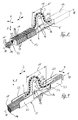
- 5 to 8 show further embodiments of a cable harness 13.
- the detour section 25 of the cable harness 13 is located between the two sections with the casing 14. It is formed by a sinusoidal wave.
- the detour route 25 contains a total of five half-waves effective as loops 3.
- the loop plane is formed by the longitudinal direction 2 and the vertical direction 8.
- the loop plane is halved when viewed from the longitudinal axis 18 in the height direction 8.
- the beginning and end of each loop 3 are cut by the longitudinal axis 18.
- the cable bundle 19 is surrounded by a flexible enveloping part 20, for example extrusion-coated with an elastic plastic.
- the enveloping part 20 has a rectangular cross section when viewed in the longitudinal direction 2 of the line. This cross section is arranged in the area of the loop ends 4, 4 ′ centrally around the longitudinal axis 18 and is substantially smaller than the rectangular cross section of the sheathing 14, which is also viewed in the longitudinal direction 2 of the wire.
- the explanations in FIG. 4 apply to the design and arrangement of the fixing webs 16.
- the fixing webs 16 have a rectangular cross section when viewed in the longitudinal direction 2 of the line. Seen in the vertical direction 8, they are arranged in the lower corner regions of the mutually facing rectangular end faces of the envelopes 14 and molded there. It is also conceivable that the fixing webs 16 are longer than the effective lengths 15. In this case, the ends of the fixing webs 16, which are not visible in FIG. 5, are surrounded by the envelopes 14.
- the wiring harness 13 shown in FIG. 5 can be seen in FIG. 6.
- the fixing webs 16 are however severed.
- the detour section of the cable harness 13 provided with the enveloping part 20 is completely stretched in the longitudinal direction 2 of the cable, so that the maximum effective length 15 of the detour section 25 is reached.
- the cable harness 13 in FIG. 7 contains two areas, each with a sheath 14.
- the design and arrangement of the sheaths 14 and the fixing webs 16 and their mutual connections essentially correspond to the description in FIG. 5 and FIG. 6.
- the line bundle 19 is surrounded by the flexible envelope part 20.
- the enveloping part 20 has a rectangular outer contour when viewed in the longitudinal direction 2 of the line. In the area of the loop ends 4, 4 ', the enveloping part 20 is arranged on the envelopes 14 analogously to the description in FIG. 5.
- the detour section 25 of the wiring harness 13 contains two loops 3. They lie on top of one another in the height direction 8. In order to ensure that the loops 3 are fixed in this way, the beginning and the end of each loop 3 - viewed in the vertical direction 8 - are connected by the fixing element 5 (FIG. 1). The loops 3 can also be held in their deflected position by means of a retaining band comprising these in the vertical direction 8 and transverse direction 9.
- This configuration of the detour section 25, seen in the longitudinal direction 2 of the line results in an only insignificantly enlarged cross-section compared to the corresponding cross-section of the cable harness 13 in the area of the envelopes 14.
- This configuration of the detour route 25 can preferably be used with ribbon cables. Even with large changes in length between two different length versions, this arrangement of the detour route 25 is favorable.
- the active length 15 can be flexibly adapted to changes in length which were not exactly known beforehand. For this purpose, only a number of fixing elements corresponding to the necessary change in the effective length is released.
- the detour 25 of the wire harness is formed by a loop 3.
- the arrangement and configuration of the loop 3 essentially corresponds to that in FIG. 4.
- the configuration of the fixing webs 16 and their arrangement on the envelopes 14 correspond to the explanations in FIGS. 5 to 7.
- the envelopes 14 have a trapezoidal cross-section as seen in the longitudinal direction 2 of the line.
- One of the two envelopes 14 is provided on all of its surfaces running in the longitudinal direction 2 of the line with incisions 21 arranged perpendicular to this direction.
- Two incisions 21 running in the transverse direction 9 and two in the vertical direction 8 form a closed circulation around the longitudinal axis 18 distributed.
- the distances themselves are formed by ribs 26 protruding radially around the line bundle 19, the cross section of which corresponds to that of the sheathing 14 not provided with the cuts 21.
- the casing 14 with the ribs 26 thus has the appearance of an accordion which is pulled apart in the longitudinal direction 2 of the line.
- Fig. 8 it can be seen that the individual cables 11 are held together by a retaining strap 22 surrounding them as a bundle 19.
- the tether 22 is in turn surrounded by the envelopes 14.
- the casing 14 provided with the ribs 26 has the advantage that cables 11 or cable bundles 19 lying in the cable harness 13 do not reach the outside in the vertical direction 8 and the cable harness 13, in contrast to smooth surfaces of the casing 14, is better protected from mechanical damage, for example by abrasion of the surface the envelope 14 is protected. This also protects the cables 11 or the bundle of lines 19 from damage. In the case of electrical lines, a risk of short-circuits is avoided.
- the incisions 21 cause the otherwise dimensionally stable envelope 14 to be bendable to a certain degree.
- the incisions 21 can also be used to snap the cable harness 13 into a holding device or to fix it in a stationary manner in some other way.
- Fig. 9 shows a guide channel 1, which is equipped with the line bundle 19.
- the detour route of the line bundle 19 is arranged and configured as a loop 3 analogous to the explanations in FIG. 8.
- the individual cables 11 of the line bundle 19 are encased by the holding band 22.
- the sheathing of the cables 11 by the retaining band 22 extends somewhat beyond the loop ends 4, 4 'in the longitudinal direction 2 of the line.
- the guide channel 1 takes over the bundling and sheathing function for the cables 11.
- the guide channel 1 has a U-shaped cross section as seen in the longitudinal direction 2 of the line.
- the guide channel 1 contains two channel side walls 23 arranged parallel to one another and running in the longitudinal direction 2 of the duct. They lie in a plane formed by the longitudinal direction 2 and the vertical direction 8.
- the channel side walls 23 lying opposite one another in the transverse direction 9 are connected to one another by a channel floor 24 corresponding to the U-base.
- Channel side walls 23 and channel floor 24 are arranged perpendicular to one another.
- the channel side walls 23 are reduced to the dimensions of the fixing webs 16. Seen in the transverse direction 9, the guide channel 1 therefore receives two opposing rectangular incisions.
- the fixing webs 16 are an integral part of the channel side walls 23 and connect the regions of the channel side walls 23 which are opposite one another in the longitudinal direction 2 of the duct and are closest to the channel bottom 24. So that the two guide channel sections can be moved in the longitudinal direction 2 of the line after the fixing webs 16 have been severed, there is no channel floor 24 in the area of the effective length 15.
- Each fixing web 16 is separated by two nominal separation points 17 into two parts of approximately the same length.
- the two predetermined separation points 17 each of a fixing web 16 are designed as V-shaped incisions in the surfaces of the fixing web 16 opposite in the vertical direction 8.
- the guide channels 1 or cable harnesses 13 shown in the figures each have a predetermined length which is oriented in the longitudinal direction 2 of the line and is adapted to the normal version of the vehicle type.
- the fixing element 5 In order to change the effective length 15 of the subject matter of the invention, the fixing element 5, the bandage 12 and / or the predetermined separation points 17 of the fixing webs 16 are severed.
- the fixing element 5 is loosened, for example, by a cut, whereby the enveloping and protective function of the guide channel 1 (FIG. 1) or of the enveloping part 20 (FIG. 7) is not impaired.
- the fixing element 5 can also be designed, for example, in the manner of a tearable plastic bottle.
- the fixing webs 16 are preferably rigid so that they can also be severed in the area of the predetermined separation point 17 by a simple break.
- the effective length 15 can be increased and the cable bundle 19 pulled apart to a length adapted to the long version in the longitudinal direction 2 of the cable.
- the loops 3 are at least partially canceled.
Claims (21)
- Faisceau de câbles (13) contenant des conduites d'alimentation (11) sous forme rassemblée, ou canal de guidage (1) destiné à recevoir les conduites d'alimentation (11) - désignés tous deux brièvement par la suite comme "porte-câbles" -, comprenant un tronçon détourné (25) du faisceau de câbles (11, 19) agencé dans une région du faisceau,
caractérisé par un élément de fixation (5, 12, 16) qui maintient effectif le tronçon détourné (25), dont la libération irréversible permet d'allonger le faisceau de câbles (11, 19), sans influence sur les fonctions de conduction, quant à sa longueur effective (15) jusqu'à une version longue, en particulier pour véhicules automobiles. - Porte-câbles selon la revendication 1, caractérisé en ce que le tronçon détourné (25) présente la forme d'une boucle (3) située au moins à l'extérieur de l'axe longitudinal (18) du porte-câbles (1, 11).
- Porte-câbles selon la revendication 2, caractérisé en ce que le plan de la boucle est disposé à côté de l'axe longitudinal (18) du porte-câbles (1, 11).
- Porte-câbles selon la revendication 2, caractérisé en ce que l'axe longitudinal (18) s'étend dans le plan de la boucle et recoupe alors le tronçon détourné (25).
- Porte-câbles selon l'une quelconque des revendications 2 à 4, caractérisé en ce que la boucle (3) a la forme d'un Ω.
- Porte-câbles selon l'une quelconque des revendications 1 à 3, caractérisé en ce que le tronçon détourné (25) comporte plusieurs boucles (3) arrangées en succession dans la direction longitudinale (2).
- Porte-câbles selon la revendication 4, caractérisé en ce que le tronçon détourné (25) est formé par une ondulation sinusoïdale.
- Porte-câbles selon la revendication 7, caractérisé en ce que l'ondulation s'étend dans la direction longitudinale (2).
- Porte-câbles selon l'une ou plusieurs des revendications précédentes, caractérisé en ce que l'élément de fixation (5, 12, 16) relie ensemble les extrémités (4, 4') du tronçon détourné (25) à une distance raccourcie par rapport à leur longueur.
- Porte-câbles selon la revendication 9, caractérisé en ce que l'élément de fixation (5, 12, 16) relie ensemble les extrémités (4, 4') du tronçon détourné (25) dans une position de contact mutuel.
- Porte-câbles selon la revendication 10, caractérisé en ce que l'élément de fixation (5, 12, 16) est un bandage, une bande ou une pince.
- Porte-câbles selon l'une ou plusieurs des revendications précédentes, caractérisé en ce que l'élément de fixation (5, 12, 16) est une jonction à intégration de matière entre les conduites d'alimentation (11), entre leurs isolations, ou entre les régions du porte-câbles (1, 13) qui sont situées dans la zone des extrémités (4, 4') du tronçon détourné (25).
- Porte-câbles selon la revendication 12, caractérisé en ce que le blocage par intégration de matière est produit par une liaison soudée.
- Porte-câbles selon la revendication 9, caractérisée en ce que l'élément de fixation est un élément de raccordement (16) qui est intégré et fixé par des ses extrémités dans le porte-câbles (1, 13).
- Porte-câbles selon la revendication 9, caractérisé en ce que l'élément de fixation (5, 12, 16) est formé à partir du matériau du porte-câbles (1, 13), et est formé d'une seule pièce avec celui-ci, en particulier injecté en matière plastique.
- Porte-câbles selon l'une ou l'autre des revendications 14 et 15, caractérisé en ce que l'élément de fixation formé d'une seule pièce à partir du matériau du porte-câbles (1, 13) contient l'élément de liaison (16) sous la forme d'un insert de renfort.
- Porte-câbles selon l'une ou plusieurs des revendications précédentes, caractérisé en ce que l'élément de fixation (5, 12, 16) comporte un emplacement de rupture désiré (17).
- Porte-câbles selon l'une ou plusieurs des revendications précédentes, caractérisé en ce qu'au moins un élément de fixation (5, 12, 16) est agencé parallèlement à l'axe longitudinal (18), en s'étendant le long du porte-câbles (1, 13).
- Porte-câbles selon l'une ou plusieurs des revendications précédentes, caractérisé en ce que le canal de guidage (1) présente à l'extérieur du tronçon détourné (25) une section transversale en forme de U, et en ce que les régions du canal de guidage (1) voisines du tronçon détourné (25) sont reliées ensemble au moyen de deux éléments de fixation (16), chaque élément de fixation reliant ensemble les régions en équerre, en vis-à-vis dans la direction longitudinale, de la forme en U du canal de guidage (1).
- Porte-câbles selon l'une ou plusieurs des revendications précédentes, caractérisé en ce que le canal de guidage (1) est une goulotte tubulaire comportant une fente d'introduction (7), qui s'étend approximativement à l'axe longitudinal (18) et traverse son enveloppe pour la mise en place du faisceau de câbles (11, 19).
- Porte-câbles selon l'une ou plusieurs des revendications précédentes, caractérisé en ce qu'une enveloppe (14) qui entoure le faisceau de câbles (11, 19), comporte dans sa région voisine du tronçon détourné (25), des saillies qui se projettent radialement, en particulier des nervures (26) qui s'étendent sur la totalité de la périphérie, en tant que protection mécanique contre les endommagements.
Applications Claiming Priority (4)
| Application Number | Priority Date | Filing Date | Title |
|---|---|---|---|
| DE9112525U | 1991-10-04 | ||
| DE9112525 | 1991-10-04 | ||
| DE9200909U | 1992-01-27 | ||
| DE9200909U DE9200909U1 (fr) | 1992-01-27 | 1992-01-27 |
Publications (3)
| Publication Number | Publication Date |
|---|---|
| EP0535712A2 EP0535712A2 (fr) | 1993-04-07 |
| EP0535712A3 EP0535712A3 (en) | 1993-06-30 |
| EP0535712B1 true EP0535712B1 (fr) | 1995-05-10 |
Family
ID=25958730
Family Applications (1)
| Application Number | Title | Priority Date | Filing Date |
|---|---|---|---|
| EP92116985A Revoked EP0535712B1 (fr) | 1991-10-04 | 1992-10-05 | Faisceau de câble ou puits à câbles, particulièrement pour une voiture automobile |
Country Status (3)
| Country | Link |
|---|---|
| EP (1) | EP0535712B1 (fr) |
| DE (1) | DE59202139D1 (fr) |
| ES (1) | ES2073224T3 (fr) |
Families Citing this family (12)
| Publication number | Priority date | Publication date | Assignee | Title |
|---|---|---|---|---|
| JP3293744B2 (ja) * | 1996-07-15 | 2002-06-17 | 矢崎総業株式会社 | ドア用回路体の組付構造 |
| US6120327A (en) * | 1997-07-22 | 2000-09-19 | Lear Automotive Dearborn, Inc. | Foam wire harness with shape memory |
| DE69720987T2 (de) * | 1997-09-04 | 2003-11-06 | Delphi Automotive Systems Gmbh | Zündungsschutzsystem |
| US6610929B1 (en) * | 1999-01-12 | 2003-08-26 | Autonetworks Technologies, Ltd. | Wire harness for removing from a vehicle |
| AT501303B8 (de) * | 2004-09-30 | 2007-02-15 | Siemens Transportation Systems | Verfahren und vorrichtung zum konfektionieren eines jumperschlauchs-kabels |
| EP1957318A1 (fr) * | 2005-11-28 | 2008-08-20 | Renault Trucks | Dispositif de maintien pour un faisceau électrique |
| JP5074757B2 (ja) * | 2006-12-19 | 2012-11-14 | 矢崎総業株式会社 | 給電装置とそれを用いたハーネス配索構造 |
| FR2929900B1 (fr) | 2008-04-09 | 2010-06-04 | Peugeot Citroen Automobiles Sa | Gouttiere pour cable et vehicule automobile comprenant une telle gouttiere |
| JP5654363B2 (ja) * | 2011-01-20 | 2015-01-14 | 矢崎総業株式会社 | 導電路構造及びワイヤハーネス |
| JP6346844B2 (ja) * | 2014-11-04 | 2018-06-20 | 矢崎総業株式会社 | 導電路接続部材 |
| CN106524024B (zh) * | 2015-09-11 | 2019-07-12 | 本田技研工业(中国)投资有限公司 | 车灯配线安装结构 |
| DE102018213518A1 (de) * | 2018-08-10 | 2020-02-13 | Bayerische Motoren Werke Aktiengesellschaft | Leitungsanordnung, Bauteilanordnung und Arbeitsvorrichtung |
Family Cites Families (2)
| Publication number | Priority date | Publication date | Assignee | Title |
|---|---|---|---|---|
| FR1152317A (fr) * | 1956-06-13 | 1958-02-14 | Conducteur électrique extensible | |
| FR2611999B1 (fr) * | 1987-03-05 | 1989-06-30 | Peugeot | Dispositif de liaison electrique entre deux faisceaux de fils conducteurs et vehicule automobile equipe de ce dispositif |
-
1992
- 1992-10-05 DE DE59202139T patent/DE59202139D1/de not_active Expired - Lifetime
- 1992-10-05 EP EP92116985A patent/EP0535712B1/fr not_active Revoked
- 1992-10-05 ES ES92116985T patent/ES2073224T3/es not_active Expired - Lifetime
Also Published As
| Publication number | Publication date |
|---|---|
| EP0535712A3 (en) | 1993-06-30 |
| ES2073224T3 (es) | 1995-08-01 |
| DE59202139D1 (de) | 1995-06-14 |
| EP0535712A2 (fr) | 1993-04-07 |
Similar Documents
| Publication | Publication Date | Title |
|---|---|---|
| DE102007040812B4 (de) | Kabelschutz- und -führungsvorrichtung vom Falttyp | |
| DE60214024T2 (de) | Befestigungsvorrichtung für kabelbaum | |
| EP0268869B1 (fr) | Dispositif à tuyau protecteur en matériau synthétique pour conduites | |
| EP0535712B1 (fr) | Faisceau de câble ou puits à câbles, particulièrement pour une voiture automobile | |
| DE3819549A1 (de) | Schutzvorrichtung fuer gebuendelte straenge | |
| DE102018217839A1 (de) | Kabelbaumschutzeinrichtung und Herstellungsverfahren für den Kabelbaum | |
| DE112018005871T5 (de) | Kabelbaum-Trägerelement, mit Trägerelement versehener Kabelbaum und Trägerstruktur für einen mit Trägerelement versehenen Kabelbaum | |
| DE60107000T3 (de) | Vorrichtung zum Tragen und Führen eines Bündels elektrischer Leiter, welche das Folgen von Bewegungen eines Vordersitzes eines Kraftfahrzeugs gestatten | |
| DE102007041663A1 (de) | Einrichtung zum Führen von Leitungen, Schläuchen oder dergleichen | |
| DE19921351C2 (de) | Kabelstrangbefestigungsanordnung | |
| DE102005053028B4 (de) | Stromversorgungsvorrichtung | |
| DE102005046194B4 (de) | Kabelkanal mit Kanalsegmenten | |
| DE3437448A1 (de) | Geraet zur herstellung von kabel-spleissverbindungen, insbesondere bei lichtleiter-kabeln | |
| DE112018007293T5 (de) | Kabelbaumschutzvorrichtung und Kabelbaumverlegestruktur unter Verwendung derselben | |
| DE102019214725A1 (de) | Kabelbaum | |
| DE3545517C2 (fr) | ||
| DE102004005307B3 (de) | Verschließmittel für geschlitzte Rohre, insbesondere Wellrohre zur schützenden Ummantelung von elektrischen Kabeln in Kraftfahrzeugen | |
| DE102016112758B4 (de) | Halteteil und verfahren zum befestigen von elektrischen leitungen sowie leitungsanordnung in einem fahrzeug | |
| DE19606643C2 (de) | Befestigungseinrichtung für Kabelbäume und Verwendung der Befestigungseinrichtung | |
| DE102017209969A1 (de) | Kabelbaum | |
| DE102007014064B4 (de) | Vorrichtung zur geschützten Anordnung optischer Fasern | |
| DE102021107321A1 (de) | Schutzvorrichtung und Kabelbaum | |
| DE102004005310B4 (de) | Geschlitztes Rohr, insbesondere Wellrohr zur schützenden Ummantelung von elektrischen Kabeln in Kraftfahrzeugen, sowie ein das Rohr verschließendes Verschlußmittel | |
| DE102021213394B4 (de) | Vorrichtung zum Anordnen von Kabeln und/oder Kabelbündeln in einem Kabelbaum und Verfahren zum Anordnen von Kabeln und/oder Kabelbündeln in einem Kabelbaum | |
| DE102021118101B4 (de) | Halteteil |
Legal Events
| Date | Code | Title | Description |
|---|---|---|---|
| PUAI | Public reference made under article 153(3) epc to a published international application that has entered the european phase |
Free format text: ORIGINAL CODE: 0009012 |
|
| AK | Designated contracting states |
Kind code of ref document: A2 Designated state(s): BE DE DK ES FR GB GR IE IT LU NL PT |
|
| PUAL | Search report despatched |
Free format text: ORIGINAL CODE: 0009013 |
|
| AK | Designated contracting states |
Kind code of ref document: A3 Designated state(s): BE DE DK ES FR GB GR IE IT LU NL PT |
|
| 17P | Request for examination filed |
Effective date: 19930608 |
|
| 17Q | First examination report despatched |
Effective date: 19941013 |
|
| GRAA | (expected) grant |
Free format text: ORIGINAL CODE: 0009210 |
|
| AK | Designated contracting states |
Kind code of ref document: B1 Designated state(s): BE DE DK ES FR GB GR IE IT LU NL PT |
|
| PG25 | Lapsed in a contracting state [announced via postgrant information from national office to epo] |
Ref country code: NL Free format text: LAPSE BECAUSE OF FAILURE TO SUBMIT A TRANSLATION OF THE DESCRIPTION OR TO PAY THE FEE WITHIN THE PRESCRIBED TIME-LIMIT Effective date: 19950510 Ref country code: DK Effective date: 19950510 Ref country code: BE Effective date: 19950510 |
|
| REG | Reference to a national code |
Ref country code: IE Ref legal event code: FG4D Free format text: 63750 |
|
| REF | Corresponds to: |
Ref document number: 59202139 Country of ref document: DE Date of ref document: 19950614 |
|
| GBT | Gb: translation of ep patent filed (gb section 77(6)(a)/1977) |
Effective date: 19950605 |
|
| PGFP | Annual fee paid to national office [announced via postgrant information from national office to epo] |
Ref country code: DE Payment date: 19950801 Year of fee payment: 4 |
|
| REG | Reference to a national code |
Ref country code: ES Ref legal event code: FG2A Ref document number: 2073224 Country of ref document: ES Kind code of ref document: T3 |
|
| ITF | It: translation for a ep patent filed |
Owner name: UFFICIO BREVETTI RICCARDI & C. |
|
| PG25 | Lapsed in a contracting state [announced via postgrant information from national office to epo] |
Ref country code: PT Effective date: 19950810 |
|
| ET | Fr: translation filed | ||
| PG25 | Lapsed in a contracting state [announced via postgrant information from national office to epo] |
Ref country code: GR Free format text: LAPSE BECAUSE OF FAILURE TO SUBMIT A TRANSLATION OF THE DESCRIPTION OR TO PAY THE FEE WITHIN THE PRESCRIBED TIME-LIMIT Effective date: 19950811 |
|
| PGFP | Annual fee paid to national office [announced via postgrant information from national office to epo] |
Ref country code: FR Payment date: 19950817 Year of fee payment: 4 |
|
| PGFP | Annual fee paid to national office [announced via postgrant information from national office to epo] |
Ref country code: ES Payment date: 19951023 Year of fee payment: 4 |
|
| PG25 | Lapsed in a contracting state [announced via postgrant information from national office to epo] |
Ref country code: LU Free format text: LAPSE BECAUSE OF NON-PAYMENT OF DUE FEES Effective date: 19951031 |
|
| NLV1 | Nl: lapsed or annulled due to failure to fulfill the requirements of art. 29p and 29m of the patents act | ||
| PG25 | Lapsed in a contracting state [announced via postgrant information from national office to epo] |
Ref country code: IE Free format text: LAPSE BECAUSE OF NON-PAYMENT OF DUE FEES Effective date: 19951115 |
|
| REG | Reference to a national code |
Ref country code: IE Ref legal event code: FD4D Ref document number: 63750 Country of ref document: IE |
|
| PLBI | Opposition filed |
Free format text: ORIGINAL CODE: 0009260 |
|
| PLBF | Reply of patent proprietor to notice(s) of opposition |
Free format text: ORIGINAL CODE: EPIDOS OBSO |
|
| 26 | Opposition filed |
Opponent name: BAYERISCHE MOTOREN WERKE AKTIENGESELLSCHAFT Effective date: 19960131 |
|
| PLBF | Reply of patent proprietor to notice(s) of opposition |
Free format text: ORIGINAL CODE: EPIDOS OBSO |
|
| PG25 | Lapsed in a contracting state [announced via postgrant information from national office to epo] |
Ref country code: DE Effective date: 19960921 |
|
| PLBF | Reply of patent proprietor to notice(s) of opposition |
Free format text: ORIGINAL CODE: EPIDOS OBSO |
|
| RDAH | Patent revoked |
Free format text: ORIGINAL CODE: EPIDOS REVO |
|
| RDAG | Patent revoked |
Free format text: ORIGINAL CODE: 0009271 |
|
| STAA | Information on the status of an ep patent application or granted ep patent |
Free format text: STATUS: PATENT REVOKED |
|
| GBPR | Gb: patent revoked under art. 102 of the ep convention designating the uk as contracting state |
Free format text: 961007 |
|
| 27W | Patent revoked |
Effective date: 19961007 |