EP0887902A2 - Enveloppe de protection flexible - Google Patents
Enveloppe de protection flexible Download PDFInfo
- Publication number
- EP0887902A2 EP0887902A2 EP98201960A EP98201960A EP0887902A2 EP 0887902 A2 EP0887902 A2 EP 0887902A2 EP 98201960 A EP98201960 A EP 98201960A EP 98201960 A EP98201960 A EP 98201960A EP 0887902 A2 EP0887902 A2 EP 0887902A2
- Authority
- EP
- European Patent Office
- Prior art keywords
- projections
- sleeve
- wall
- sleeve according
- deformable
- Prior art date
- Legal status (The legal status is an assumption and is not a legal conclusion. Google has not performed a legal analysis and makes no representation as to the accuracy of the status listed.)
- Withdrawn
Links
- 230000001681 protective effect Effects 0.000 title claims abstract description 12
- 239000004033 plastic Substances 0.000 claims description 6
- 229920003023 plastic Polymers 0.000 claims description 6
- 239000000463 material Substances 0.000 description 7
- 239000006260 foam Substances 0.000 description 6
- 239000004677 Nylon Substances 0.000 description 4
- 229920001778 nylon Polymers 0.000 description 4
- 229920000728 polyester Polymers 0.000 description 4
- 238000000034 method Methods 0.000 description 3
- 238000005299 abrasion Methods 0.000 description 2
- 238000009413 insulation Methods 0.000 description 2
- 239000004743 Polypropylene Substances 0.000 description 1
- 229920005830 Polyurethane Foam Polymers 0.000 description 1
- 238000009954 braiding Methods 0.000 description 1
- 239000011248 coating agent Substances 0.000 description 1
- 238000000576 coating method Methods 0.000 description 1
- 230000000694 effects Effects 0.000 description 1
- 239000013536 elastomeric material Substances 0.000 description 1
- 239000004744 fabric Substances 0.000 description 1
- 239000003365 glass fiber Substances 0.000 description 1
- 239000003779 heat-resistant material Substances 0.000 description 1
- 238000011065 in-situ storage Methods 0.000 description 1
- 239000011810 insulating material Substances 0.000 description 1
- 238000009940 knitting Methods 0.000 description 1
- 238000004806 packaging method and process Methods 0.000 description 1
- -1 polypropylene Polymers 0.000 description 1
- 229920001155 polypropylene Polymers 0.000 description 1
- 239000011496 polyurethane foam Substances 0.000 description 1
- 239000012858 resilient material Substances 0.000 description 1
- 229920002379 silicone rubber Polymers 0.000 description 1
- 239000004945 silicone rubber Substances 0.000 description 1
- 239000004753 textile Substances 0.000 description 1
- 238000009941 weaving Methods 0.000 description 1
Images
Classifications
-
- H—ELECTRICITY
- H02—GENERATION; CONVERSION OR DISTRIBUTION OF ELECTRIC POWER
- H02G—INSTALLATION OF ELECTRIC CABLES OR LINES, OR OF COMBINED OPTICAL AND ELECTRIC CABLES OR LINES
- H02G3/00—Installations of electric cables or lines or protective tubing therefor in or on buildings, equivalent structures or vehicles
- H02G3/02—Details
- H02G3/04—Protective tubing or conduits, e.g. cable ladders or cable troughs
- H02G3/0462—Tubings, i.e. having a closed section
- H02G3/0481—Tubings, i.e. having a closed section with a circular cross-section
Definitions
- This invention is concerned with a flexible protective sleeve for use in protecting an elongated member, such as a wire, a bundle of wires, or a pipe.
- Such sleeves conventionally, are long in relation to their width, ie at least three times the width depending on the length to be protected.
- Such sleeves comprise a generally tubular wall for at least substantially surrounding the member.
- the wall may have the form of a hollow cylinder.
- the wall of such a sleeve is made from abrasion resistant non-resilient material.
- Such sleeves may also incidently act to insulate a member from heat or to protect other components from heat from the elongated member, the wall in these cases is made from heat-resistant material.
- Such sleeves are used, for example, in the engine compartments of vehicle.
- the wall of such a sleeve comprises portions or members which are movable relative to one another to accommodate curvature of the sleeve.
- the wall of a sleeve of this type may be formed from sheet material, eg plastics material such as nylon.
- the sheet material may be formed into a convoluted tube, the convolutions being movable relative to one another to accommodate curvature moving apart on the outside of a curve and together on the inside of a curve.
- the wall of a sleeve of this type may be formed from filaments or yarns of, for example, plastics material such as nylon, polyester or polypropylene.
- the filaments or yarns are formed into a sheet by a textile operation such as braiding, weaving or knitting. Glass fibre and other organic and inorganic fibres can also be used.
- the wall can be formed as a tube or as a flat sheet which is subsequently wrapped around into a tubular form.
- the filaments or yarns are movable relative to one another, moving closer together or farther apart, to accommodate curvature of the sleeve.
- Some flexible protective sleeves have a longitudinal slit in their wall to enable the sleeve to be installed over a pipe or wire which is already in situ.
- a conventional flexible protective sleeve is a relatively loose fit over an elongated member. This can be advantageous in, for example, situations where thermal insulation is an issue but has the disadvantage is that the sleeve may rattle on the elongated member causing undesirable noise. Another disadvantage is that the sleeve can become displaced along the member in service so that it may not be appropriately positioned to perform its function.
- the invention provides a flexible protective sleeve for use in protecting an elongated member, the sleeve being long in relation to its width, the sleeve comprising a generally tubular wall for at least substantially surrounding the member, characterised in that the sleeve also comprises resiliently-deformable projections projecting from an inner surface of the wall, the projections being positioned at intervals along the inner surface of said wall, each projection being arranged so that it acts to cushion relative movement between the member and the wall.
- the projections cushion relative movement between the elongated member and the wall, thereby preventing noise-generating impacts.
- the projections can also be arranged to press the elongated member either between projections on opposite sides of the member or between a projection and the wall, thereby gripping the member and acting to prevent the sleeve from being displaced along the member.
- the projections can be arranged to hold the wall out of contact with the member. This has an advantage, in situations where thermal insulation is an issue, as the insulating effect is improved by the member being held out of contact with the wall whereas, in conventional sleeves, the wall is supported by contact with the member.
- the projections may be integral with the wall.
- they may be provided as projections from filaments forming the wall.
- plastics monofilaments are formed by the double needle bar process (used for forming eg hospital mattresses or helmet interiors) into two knitted sheets joined by filaments that run between the sheets, normally of each sheet; these filaments are cut through halfway between the sheets; and each sheet is rolled into a tubular form with the filaments on the inside and forming said projections.
- the projections may be adhered to the wall.
- a sheet of material to form the wall may have a supporting sheet which supports the projections adhered thereto before being rolled into tubular form with the projections on the inside.
- Possible supporting sheets are woven or knitted fabrics.
- the supporting sheet is made of foam having integral foam projections (a suitable material is "profile-cut" foam used in the packaging industry).
- the projections may take many forms. For example, they may be long and thin so that they are resiliently-deformable by being bent out of a their unloaded configuration.
- the projections may be plastics monofilaments, eg of polyester or nylon, having a diameter of 2.5mm to 0.1mm. The monofilaments may have the form of a hook, ie their free ends may be turned over through 90° or more.
- the projections may be made to be compressible lengthwise, eg they may take the form of columns, cones or pyramids made, eg, from elastomeric material, eg silicone rubber, or resilient foam. A loop of plastics monofilament with both its ends secured to or integral with the wall can form a lengthwise compressible projection.
- the projections may have a grip-enhancing coating thereon or their tips may be enlarged to increase grip.
- the projections may be uniformly distributed circumferentially of the sleeve, for example the projections may be uniformly distributed over the entire inner surface of the wall.
- the projections may be arranged in groups at intervals along the sleeve, for example the wall of the sleeve may be convoluted and the projections may be located on the portions of the inner surface which have the smallest diameter.
- the projections may follow a helical path along the sleeve. The number of projections per unit length of sleeve varies with the form of projection and the application in which the sleeve is to be used.
- the projections may project normally of the inner surface of the wall or may be inclined along the sleeve to improve the grip on the sleeve. Some of the projections may be inclined in one direction along the sleeve while others are inclined in the opposite direction. In one possibility, the projections are arranged in rings with the direction of inclination alternating between successive rings.
- the projections may project from the inner surface of the wall by at least 10%, eg 30%, of the width of the space surrounded by the wall. In some cases, this projection is 50% or more of said width so that the projections mingle with one another at the centre of the sleeve. Preferably, no member can be introduced into the sleeve without deforming the projections.
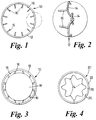
- the first illustrative flexible protective sleeve 10 is for use in protecting an elongated member, eg the wire W shown in Figure 3.
- the sleeve 10 is long in relation to its width, being 2 cms in diameter and more than 30 cms long.
- the sleeve 10 comprises a generally tubular wall 12 for surrounding the wire W.
- the wall 12 is formed from polyester monofilaments 14 having a diameter of approximately 0.5 mm. To form the wall 12, the monofilaments 14 are knitted into a sheet and the sheet is rolled into the form of a hollow cylinder.
- the sleeve 10 also comprises resiliently-deformable projections 16 projecting from an inner surface 18 of the wall 12.
- the projections 16 are positioned at intervals along the inner surface 18 and are arranged so that they act to cushion relative movement between the wire W and the wall 12, thereby preventing noise from impacts therebetween.
- the projections 16 are in the form of cylindrical monofilaments of polyester projecting from and integral with some of the monofilaments 14 forming the wall 12. Thus, the projections are integral with the wall 12.
- Each projection 16 extends normally of the surface 18 towards the centre of the sleeve 10.
- the projections 16 are uniformly distributed over the surface 18, both circumferentially about the centre of the sleeve 10 and along the sleeve, so that they press on the wire W gripping it and centralising it within the wall 12.
- the projections 16 In their unloaded configuration (shown in Figure 1), the projections 16 extend straight towards the centre of the sleeve 10, the projections 16 having their inner ends nearer to the centre of the sleeve 10 than the radius of the wire W. However, the projections 16 are resiliently-deformable by being bent out of their unloaded configuration. Thus, as shown in Figure 3, introduction of the wire W into the interior of the sleeve 10 bends the projections 16 out of their unloaded condition. In this bent condition, each projection presses on the wire W and, as the projections 16 are evenly distributed around the wire W, the wire W is centralised in the sleeve 10 by the sleeve moving to a position relative to the wire in which the forces applied by the projections 16 to the wire are balanced.
- the second illustrative sleeve 20 shown in Figure 2 is also a flexible protective sleeve for use in protecting an elongated member and is long in relation to its width.
- the sleeve 20 comprises a generally tubular wall 22 for at least substantially surrounding the member.
- the wall 22 is formed from continuous nylon sheet which is extruded in a cylindrical form and is convoluted to make it flexible.
- the sleeve 22 also comprises resiliently-deformable projections 24 projecting from an inner surface 26 of the wall.
- the projections 24 are formed from polyurethane foam and are in the form of mounds having a generally sinusoidal cross-section in both the circumferential and longitudinal directions of the sleeve.
- the projections 24 are, thus, positioned at intervals along the inner surface 26.
- the projections 24 are integral with a supporting sheet 28, also formed from foam, which is adhered to the surface 26 of said wall 22. Being formed from foam, the projections 24 are resiliently-deformable by being compressible lengthwise, ie towards the surface 26.
- the projections 24 are uniformly distributed over the surface 26 so that they are arranged so that, when they are deformed by a member surrounded by the wall 22, they cushion relative movement between the member and the wall.
- the projections 24 also press on the member and thereby act to grip the member and to centralise the member within the wall.
Landscapes
- Engineering & Computer Science (AREA)
- Architecture (AREA)
- Civil Engineering (AREA)
- Structural Engineering (AREA)
- Protection Of Pipes Against Damage, Friction, And Corrosion (AREA)
- Pipe Accessories (AREA)
- Insulating Bodies (AREA)
- Details Of Indoor Wiring (AREA)
Applications Claiming Priority (2)
| Application Number | Priority Date | Filing Date | Title |
|---|---|---|---|
| GBGB9713598.2A GB9713598D0 (en) | 1997-06-28 | 1997-06-28 | Flexible protective sleeve |
| GB9713598 | 1997-06-28 |
Publications (2)
| Publication Number | Publication Date |
|---|---|
| EP0887902A2 true EP0887902A2 (fr) | 1998-12-30 |
| EP0887902A3 EP0887902A3 (fr) | 1999-11-24 |
Family
ID=10815014
Family Applications (1)
| Application Number | Title | Priority Date | Filing Date |
|---|---|---|---|
| EP98201960A Withdrawn EP0887902A3 (fr) | 1997-06-28 | 1998-06-11 | Enveloppe de protection flexible |
Country Status (4)
| Country | Link |
|---|---|
| US (1) | US6112770A (fr) |
| EP (1) | EP0887902A3 (fr) |
| JP (1) | JPH1163372A (fr) |
| GB (2) | GB9713598D0 (fr) |
Cited By (19)
| Publication number | Priority date | Publication date | Assignee | Title |
|---|---|---|---|---|
| GB2336419A (en) * | 1998-04-18 | 1999-10-20 | Federal Mogul Technology Ltd | Protective sleeve |
| EP1587193A3 (fr) * | 2004-04-13 | 2006-08-02 | Karl Kramer | Dispositif protecteur de câble |
| CN104089149A (zh) * | 2014-06-17 | 2014-10-08 | 成都棕通石油配件有限公司 | 一种保温石油管道 |
| CN104989916A (zh) * | 2015-05-26 | 2015-10-21 | 成都高普石油工程技术有限公司 | 一种保温型石油管道 |
| CN105840955A (zh) * | 2016-06-22 | 2016-08-10 | 陈明炬 | 一种防磨损的管道防护罩装置及其安装方法 |
| CN105840954A (zh) * | 2016-06-22 | 2016-08-10 | 邴萍娟 | 一种耐腐蚀的管道安全防护结构及其安装方法 |
| CN105864577A (zh) * | 2016-06-22 | 2016-08-17 | 陈明炬 | 一种可靠性高的管道防护罩装置及其安装方法 |
| CN105864575A (zh) * | 2016-06-22 | 2016-08-17 | 陈明炬 | 一种密封性高的管道防护罩装置及其安装方法 |
| CN105864582A (zh) * | 2016-06-22 | 2016-08-17 | 陈明炬 | 一种简易的管道防护罩装置及其安装方法 |
| CN105864574A (zh) * | 2016-06-22 | 2016-08-17 | 陈明炬 | 一种牢固的管道防护罩装置及其安装方法 |
| CN105889704A (zh) * | 2016-06-22 | 2016-08-24 | 邴萍娟 | 一种易维护的管道防护罩装置及其安装方法 |
| CN105972386A (zh) * | 2016-06-22 | 2016-09-28 | 陈明炬 | 一种管道用的防护罩装置及其安装方法 |
| CN106015835A (zh) * | 2016-06-22 | 2016-10-12 | 陈明炬 | 一种方便维护的管道防护罩装置及其安装方法 |
| CN106015755A (zh) * | 2016-06-22 | 2016-10-12 | 陈明炬 | 一种结构稳固的管道防护罩装置及其安装方法 |
| CN106015834A (zh) * | 2016-06-22 | 2016-10-12 | 陈明炬 | 一种维护方便的管道防护罩装置及其安装方法 |
| CN106090532A (zh) * | 2016-06-22 | 2016-11-09 | 陈明炬 | 一种便捷的管道防护罩装置及其安装方法 |
| CN106090533A (zh) * | 2016-06-22 | 2016-11-09 | 陈明炬 | 一种保护性强的管道防护罩装置及其安装方法 |
| NO20161724A1 (no) * | 2016-11-01 | 2017-12-18 | Gep Holding As | Beskyttelseskappe for omslutning av kabel og/eller annet langstrakt element |
| NO345370B1 (en) * | 2019-06-18 | 2021-01-04 | Kaefer Energy As | A sheet and a method for providing a space between a pipeline and an insulating material |
Families Citing this family (21)
| Publication number | Priority date | Publication date | Assignee | Title |
|---|---|---|---|---|
| AUPP366298A0 (en) * | 1998-05-22 | 1998-06-18 | Derby Rubber Products Pty Ltd | A tile a ballast broom cowling |
| US6185859B1 (en) * | 1999-07-12 | 2001-02-13 | Texan Corporation | Tubing made from resilient plastics and devices made therefrom |
| US6167915B1 (en) * | 1999-08-30 | 2001-01-02 | Baker Hughes Inc. | Well pump electrical cable with internal bristle support |
| US20030218112A1 (en) * | 2002-05-21 | 2003-11-27 | All Rite Products, Inc. | ATV holding device |
| US7214880B2 (en) * | 2002-09-24 | 2007-05-08 | Adc Incorporated | Communication wire |
| HK1079895A1 (zh) * | 2002-09-24 | 2006-04-13 | Adc Inc. | 通信電線 |
| US7252117B1 (en) | 2004-08-13 | 2007-08-07 | Glenn William F | Reusable stub-out cover |
| EP1794486B1 (fr) * | 2004-09-28 | 2011-04-06 | Gall & Seitz Systems GmbH | Tuyau a paroi double |
| GB2428904A (en) * | 2005-07-29 | 2007-02-07 | Crp Group Ltd | Duct |
| FR2897877B1 (fr) * | 2006-02-28 | 2008-07-11 | Fed Mogul Systems Prot Group S | Gaine de protection aux chocs d'un tuyau, notamment pour conduite de carburant |
| US20080143057A1 (en) * | 2006-12-15 | 2008-06-19 | Ancra International, Llc. | Protective sleeve for use with ratcheting winch or cap |
| WO2010125550A2 (fr) * | 2009-04-27 | 2010-11-04 | Kingspan Holdings (Irl) Limited | Collecteur solaire |
| US8557358B1 (en) * | 2011-08-22 | 2013-10-15 | The United States Of America As Represented By The Secretary Of The Navy | Rolling textile protective system for textile structural members |
| US20130213515A1 (en) * | 2012-02-22 | 2013-08-22 | Joseph Robert Secoura | Insulation members employing standoff surfaces for insulating pipes, and related components and methods |
| WO2013170250A1 (fr) | 2012-05-11 | 2013-11-14 | Nomaco Inc. | Systèmes d'isolation faisant appel à des caractéristiques d'expansion pour isoler des contenants allongés soumis à des fluctuations de température extrêmes, et composants et procédés connexes |
| KR200465188Y1 (ko) | 2012-10-23 | 2013-02-06 | 주식회사 대원인듀스트릴 | 배관커버용 간격유지대 |
| USD707419S1 (en) | 2013-02-07 | 2014-06-24 | Nisshin Foods Inc. | Macaroni |
| JP5775541B2 (ja) * | 2013-03-08 | 2015-09-09 | 株式会社ブリヂストン | 複合管 |
| WO2017024301A1 (fr) | 2015-08-06 | 2017-02-09 | Flexible Technologies, Inc. | Conduit isolé à lame d'air et procédé d'utilisation |
| US10337652B2 (en) * | 2016-10-19 | 2019-07-02 | Subcom, Llc | Separation duct having longitudinal spacers |
| JP2021110430A (ja) * | 2020-01-15 | 2021-08-02 | 株式会社イノアック住環境 | 保護管 |
Family Cites Families (19)
| Publication number | Priority date | Publication date | Assignee | Title |
|---|---|---|---|---|
| GB653855A (fr) * | ||||
| US2551710A (en) * | 1945-05-04 | 1951-05-08 | Extruded Plastics Inc | Light diffusing thermoplastic tube to encircle an elongated lighting element |
| GB648357A (en) * | 1946-10-31 | 1951-01-03 | Rue Extrusions Ltd De | Improvements in light diffusers |
| US3102740A (en) * | 1959-05-20 | 1963-09-03 | Walter A Plummer | Protective jacket for assembly about cold fluid-conveying ducts |
| GB894490A (en) * | 1960-02-15 | 1962-04-26 | Goodrich Co B F | Closed-cell sponge rubber pipe insulation |
| FR1308239A (fr) * | 1961-10-14 | 1962-11-03 | Hackethal Draht & Kabelwerk Ag | Tubes de canalisations isolés notamment tubes calorifugés et insonorisés |
| US3240233A (en) * | 1962-02-12 | 1966-03-15 | Archibald P Johnston | Guiding conduit for wire or the like |
| US3581776A (en) * | 1968-10-02 | 1971-06-01 | Dow Chemical Co | Pipe insulation structure |
| US3758701A (en) * | 1971-08-17 | 1973-09-11 | Siemens Ag | Spacer means for a superconductive electrical cable |
| GB1413397A (en) * | 1973-07-06 | 1975-11-12 | Lilja L H | Arrangement in a pipe for enclosing insulation |
| US4484024A (en) * | 1981-10-15 | 1984-11-20 | Raychem Corporation | Overcoated bulky sleeving and electrical insulation method |
| US4501302A (en) * | 1983-10-14 | 1985-02-26 | Apx Group, Inc. | Air gap pipe |
| US4688890A (en) * | 1985-03-11 | 1987-08-25 | Goodall Rubber Company | Fiber optic cable inner duct |
| JPS6398413A (ja) * | 1986-10-15 | 1988-04-28 | Smc Corp | 二重管およびその連続製造法 |
| DE4206096A1 (de) * | 1992-02-27 | 1993-09-02 | Wolf Woco & Co Franz J | Koaxialrohr |
| DE9306378U1 (de) * | 1993-04-28 | 1993-06-24 | Greiner GmbH, 7440 Nürtingen | Halte- und Schutzschlauch für Leitungen |
| US5497809A (en) * | 1994-01-05 | 1996-03-12 | Wolf; Lawrence W. | Vented bending sleeves for coaxial tubing systems |
| US5829485A (en) * | 1997-06-10 | 1998-11-03 | Bentley-Harris Inc. | Foam coated convoluted tubing |
| US5866216A (en) * | 1997-07-17 | 1999-02-02 | Davlyn Manufacturing Co., Inc. | Sound absorbent fabric sleeves |
-
1997
- 1997-06-28 GB GBGB9713598.2A patent/GB9713598D0/en active Pending
-
1998
- 1998-06-09 US US09/094,162 patent/US6112770A/en not_active Expired - Fee Related
- 1998-06-10 GB GB9812400A patent/GB2326688B/en not_active Expired - Fee Related
- 1998-06-11 EP EP98201960A patent/EP0887902A3/fr not_active Withdrawn
- 1998-06-26 JP JP10180225A patent/JPH1163372A/ja active Pending
Cited By (28)
| Publication number | Priority date | Publication date | Assignee | Title |
|---|---|---|---|---|
| GB2336419A (en) * | 1998-04-18 | 1999-10-20 | Federal Mogul Technology Ltd | Protective sleeve |
| EP1587193A3 (fr) * | 2004-04-13 | 2006-08-02 | Karl Kramer | Dispositif protecteur de câble |
| CN104089149A (zh) * | 2014-06-17 | 2014-10-08 | 成都棕通石油配件有限公司 | 一种保温石油管道 |
| CN104989916A (zh) * | 2015-05-26 | 2015-10-21 | 成都高普石油工程技术有限公司 | 一种保温型石油管道 |
| CN105840955A (zh) * | 2016-06-22 | 2016-08-10 | 陈明炬 | 一种防磨损的管道防护罩装置及其安装方法 |
| CN105840954A (zh) * | 2016-06-22 | 2016-08-10 | 邴萍娟 | 一种耐腐蚀的管道安全防护结构及其安装方法 |
| CN105864577A (zh) * | 2016-06-22 | 2016-08-17 | 陈明炬 | 一种可靠性高的管道防护罩装置及其安装方法 |
| CN105864575A (zh) * | 2016-06-22 | 2016-08-17 | 陈明炬 | 一种密封性高的管道防护罩装置及其安装方法 |
| CN105864582A (zh) * | 2016-06-22 | 2016-08-17 | 陈明炬 | 一种简易的管道防护罩装置及其安装方法 |
| CN105864574A (zh) * | 2016-06-22 | 2016-08-17 | 陈明炬 | 一种牢固的管道防护罩装置及其安装方法 |
| CN105889704A (zh) * | 2016-06-22 | 2016-08-24 | 邴萍娟 | 一种易维护的管道防护罩装置及其安装方法 |
| CN105972386A (zh) * | 2016-06-22 | 2016-09-28 | 陈明炬 | 一种管道用的防护罩装置及其安装方法 |
| CN106015835A (zh) * | 2016-06-22 | 2016-10-12 | 陈明炬 | 一种方便维护的管道防护罩装置及其安装方法 |
| CN106015755A (zh) * | 2016-06-22 | 2016-10-12 | 陈明炬 | 一种结构稳固的管道防护罩装置及其安装方法 |
| CN106015834A (zh) * | 2016-06-22 | 2016-10-12 | 陈明炬 | 一种维护方便的管道防护罩装置及其安装方法 |
| CN106090532A (zh) * | 2016-06-22 | 2016-11-09 | 陈明炬 | 一种便捷的管道防护罩装置及其安装方法 |
| CN106090533A (zh) * | 2016-06-22 | 2016-11-09 | 陈明炬 | 一种保护性强的管道防护罩装置及其安装方法 |
| CN105864575B (zh) * | 2016-06-22 | 2017-10-10 | 鲁冀管业科技股份有限公司 | 一种密封性高的管道防护罩装置及其安装方法 |
| CN105972386B (zh) * | 2016-06-22 | 2017-10-10 | 鲁冀管业科技股份有限公司 | 一种管道用的防护罩装置及其安装方法 |
| CN105889704B (zh) * | 2016-06-22 | 2017-10-27 | 曹泽琛 | 一种易维护的管道防护罩装置及其安装方法 |
| CN106015835B (zh) * | 2016-06-22 | 2017-11-10 | 肖春槐 | 一种方便维护的管道防护罩装置及其安装方法 |
| CN106015834B (zh) * | 2016-06-22 | 2017-12-08 | 泰兴市东城水处理工程有限公司 | 一种维护方便的管道防护罩装置及其安装方法 |
| CN106090532B (zh) * | 2016-06-22 | 2017-12-08 | 泰兴市东城水处理工程有限公司 | 一种便捷的管道防护罩装置及其安装方法 |
| CN106090533B (zh) * | 2016-06-22 | 2017-12-08 | 泰兴市东城水处理工程有限公司 | 一种保护性强的管道防护罩装置及其安装方法 |
| CN106015755B (zh) * | 2016-06-22 | 2017-12-08 | 泰兴市东城水处理工程有限公司 | 一种结构稳固的管道防护罩装置及其安装方法 |
| NO20161724A1 (no) * | 2016-11-01 | 2017-12-18 | Gep Holding As | Beskyttelseskappe for omslutning av kabel og/eller annet langstrakt element |
| NO341636B1 (no) * | 2016-11-01 | 2017-12-18 | Gep Holding As | Beskyttelseskappe for omslutning av kabel og/eller annet langstrakt element |
| NO345370B1 (en) * | 2019-06-18 | 2021-01-04 | Kaefer Energy As | A sheet and a method for providing a space between a pipeline and an insulating material |
Also Published As
| Publication number | Publication date |
|---|---|
| US6112770A (en) | 2000-09-05 |
| GB9812400D0 (en) | 1998-08-05 |
| GB2326688B (en) | 2002-09-11 |
| GB2326688A (en) | 1998-12-30 |
| EP0887902A3 (fr) | 1999-11-24 |
| GB9713598D0 (en) | 1997-09-03 |
| JPH1163372A (ja) | 1999-03-05 |
Similar Documents
| Publication | Publication Date | Title |
|---|---|---|
| US6112770A (en) | Flexible protective sleeve | |
| CN101389800B (zh) | 管道、尤其是燃料管用的防冲击保护包套 | |
| US6978643B2 (en) | Multiple layer insulating sleeve | |
| KR102567646B1 (ko) | 스스로 지탱하면서 팽창된 상태와 수축된 상태를 가지는 셀프 랩핑 브레이드 직물 슬리브 및 그 제조 방법 | |
| EP1994210B1 (fr) | Manchon textile de faisceau de fils compact | |
| EP3212832B1 (fr) | Gaine textile tressée avec des états dilaté et contracté autoentretenus et procédé pour le construire | |
| EP3070034B1 (fr) | Rouleau recouvert par un revêtement réalisé en matériau tricoté et dispositif l'utilisant | |
| EP3374557A1 (fr) | Manche textile tressée avec élément anti-vrillage axialement rétractable et son procédé de construction | |
| SK282731B6 (sk) | Ohybná ochranná hadica na dlhý materiál | |
| US11168415B2 (en) | Circumferentially continuous and constrictable textile sleeve and method of construction thereof | |
| US11920266B2 (en) | Convolute woven sleeve and method of construction thereof | |
| US5866216A (en) | Sound absorbent fabric sleeves | |
| US20040222013A1 (en) | Protective device for elongated objects | |
| KR20180077192A (ko) | 통합된 개구가 있고 스스로 지탱하면서 팽창된 상태와 수축된 상태를 가지는 브레이드 직물 슬리브 및 그 제조 방법 | |
| EP3737785B1 (fr) | Manchon textile tubulaire et un procédé pour sa réalisation | |
| US20180258564A1 (en) | Abrasion resistant braided convolute textile sleeve and method of construction thereof | |
| US11421356B2 (en) | Braided, reflective textile sleeve and method of construction thereof | |
| HUP0103757A2 (hu) | Szövött tömlő gumicsőhöz | |
| EP1016177A1 (fr) | Gaines souples de protection | |
| WO1999054535A1 (fr) | Gaine de protection | |
| KR102942964B1 (ko) | 가요성 내마모성 직물 슬리브 및 그 제작 방법 | |
| JP2522620B2 (ja) | 編組式フレキシブルホ―ス | |
| KR20050016600A (ko) | 다중층 절연 슬리브 | |
| MXPA01003505A (en) | Fabric sleeve for a rubber tube | |
| GB2323975A (en) | Flexible protective sleeve with flock layer |
Legal Events
| Date | Code | Title | Description |
|---|---|---|---|
| PUAI | Public reference made under article 153(3) epc to a published international application that has entered the european phase |
Free format text: ORIGINAL CODE: 0009012 |
|
| 17P | Request for examination filed |
Effective date: 19980611 |
|
| AK | Designated contracting states |
Kind code of ref document: A2 Designated state(s): DE ES FR GB IT |
|
| AX | Request for extension of the european patent |
Free format text: AL;LT;LV;MK;RO;SI |
|
| RAP1 | Party data changed (applicant data changed or rights of an application transferred) |
Owner name: FEDERAL-MOGUL TECHNOLOGY LIMITED. |
|
| PUAL | Search report despatched |
Free format text: ORIGINAL CODE: 0009013 |
|
| AK | Designated contracting states |
Kind code of ref document: A3 Designated state(s): AT BE CH CY DE DK ES FI FR GB GR IE IT LI LU MC NL PT SE |
|
| AX | Request for extension of the european patent |
Free format text: AL;LT;LV;MK;RO;SI |
|
| AKX | Designation fees paid |
Free format text: DE ES FR GB IT |
|
| STAA | Information on the status of an ep patent application or granted ep patent |
Free format text: STATUS: THE APPLICATION IS DEEMED TO BE WITHDRAWN |
|
| 18D | Application deemed to be withdrawn |
Effective date: 20050101 |