EP1584540B1 - Steering system for vehicle - Google Patents
Steering system for vehicle Download PDFInfo
- Publication number
- EP1584540B1 EP1584540B1 EP05007397A EP05007397A EP1584540B1 EP 1584540 B1 EP1584540 B1 EP 1584540B1 EP 05007397 A EP05007397 A EP 05007397A EP 05007397 A EP05007397 A EP 05007397A EP 1584540 B1 EP1584540 B1 EP 1584540B1
- Authority
- EP
- European Patent Office
- Prior art keywords
- steering
- alteration
- transmission ratio
- assist force
- steerable wheels
- Prior art date
- Legal status (The legal status is an assumption and is not a legal conclusion. Google has not performed a legal analysis and makes no representation as to the accuracy of the status listed.)
- Expired - Lifetime
Links
- 230000005540 biological transmission Effects 0.000 claims description 181
- 230000004075 alteration Effects 0.000 claims description 123
- 238000009826 distribution Methods 0.000 claims description 81
- 230000003247 decreasing effect Effects 0.000 claims description 30
- 230000007423 decrease Effects 0.000 claims description 24
- 230000004043 responsiveness Effects 0.000 description 80
- 238000013459 approach Methods 0.000 description 6
- 238000010586 diagram Methods 0.000 description 6
- 230000001133 acceleration Effects 0.000 description 4
- 238000010276 construction Methods 0.000 description 4
- 230000008859 change Effects 0.000 description 3
- 230000008878 coupling Effects 0.000 description 3
- 238000010168 coupling process Methods 0.000 description 3
- 238000005859 coupling reaction Methods 0.000 description 3
- 238000001514 detection method Methods 0.000 description 3
- 230000007246 mechanism Effects 0.000 description 3
- 238000012545 processing Methods 0.000 description 3
- 230000009467 reduction Effects 0.000 description 3
- 238000012546 transfer Methods 0.000 description 2
- 238000012935 Averaging Methods 0.000 description 1
- 230000037396 body weight Effects 0.000 description 1
- 238000004891 communication Methods 0.000 description 1
- 238000013016 damping Methods 0.000 description 1
- 230000001419 dependent effect Effects 0.000 description 1
- 238000011161 development Methods 0.000 description 1
- 230000018109 developmental process Effects 0.000 description 1
- 239000000446 fuel Substances 0.000 description 1
- 238000012986 modification Methods 0.000 description 1
- 230000004048 modification Effects 0.000 description 1
Images


Classifications
-
- B—PERFORMING OPERATIONS; TRANSPORTING
- B62—LAND VEHICLES FOR TRAVELLING OTHERWISE THAN ON RAILS
- B62D—MOTOR VEHICLES; TRAILERS
- B62D6/00—Arrangements for automatically controlling steering depending on driving conditions sensed and responded to, e.g. control circuits
- B62D6/04—Arrangements for automatically controlling steering depending on driving conditions sensed and responded to, e.g. control circuits responsive only to forces disturbing the intended course of the vehicle, e.g. forces acting transversely to the direction of vehicle travel
-
- B—PERFORMING OPERATIONS; TRANSPORTING
- B60—VEHICLES IN GENERAL
- B60W—CONJOINT CONTROL OF VEHICLE SUB-UNITS OF DIFFERENT TYPE OR DIFFERENT FUNCTION; CONTROL SYSTEMS SPECIALLY ADAPTED FOR HYBRID VEHICLES; ROAD VEHICLE DRIVE CONTROL SYSTEMS FOR PURPOSES NOT RELATED TO THE CONTROL OF A PARTICULAR SUB-UNIT
- B60W10/00—Conjoint control of vehicle sub-units of different type or different function
- B60W10/10—Conjoint control of vehicle sub-units of different type or different function including control of change-speed gearings
-
- B—PERFORMING OPERATIONS; TRANSPORTING
- B60—VEHICLES IN GENERAL
- B60W—CONJOINT CONTROL OF VEHICLE SUB-UNITS OF DIFFERENT TYPE OR DIFFERENT FUNCTION; CONTROL SYSTEMS SPECIALLY ADAPTED FOR HYBRID VEHICLES; ROAD VEHICLE DRIVE CONTROL SYSTEMS FOR PURPOSES NOT RELATED TO THE CONTROL OF A PARTICULAR SUB-UNIT
- B60W10/00—Conjoint control of vehicle sub-units of different type or different function
- B60W10/20—Conjoint control of vehicle sub-units of different type or different function including control of steering systems
-
- B—PERFORMING OPERATIONS; TRANSPORTING
- B62—LAND VEHICLES FOR TRAVELLING OTHERWISE THAN ON RAILS
- B62D—MOTOR VEHICLES; TRAILERS
- B62D5/00—Power-assisted or power-driven steering
- B62D5/008—Changing the transfer ratio between the steering wheel and the steering gear by variable supply of energy, e.g. by using a superposition gear
-
- B—PERFORMING OPERATIONS; TRANSPORTING
- B62—LAND VEHICLES FOR TRAVELLING OTHERWISE THAN ON RAILS
- B62D—MOTOR VEHICLES; TRAILERS
- B62D6/00—Arrangements for automatically controlling steering depending on driving conditions sensed and responded to, e.g. control circuits
- B62D6/007—Arrangements for automatically controlling steering depending on driving conditions sensed and responded to, e.g. control circuits adjustable by the driver, e.g. sport mode
-
- B—PERFORMING OPERATIONS; TRANSPORTING
- B62—LAND VEHICLES FOR TRAVELLING OTHERWISE THAN ON RAILS
- B62D—MOTOR VEHICLES; TRAILERS
- B62D6/00—Arrangements for automatically controlling steering depending on driving conditions sensed and responded to, e.g. control circuits
- B62D6/008—Control of feed-back to the steering input member, e.g. simulating road feel in steer-by-wire applications
Definitions
- the present invention relates to a steering system capable of altering the mode in which steerable wheels follow to the manipulation of a steering handle, in dependence on the traveling state of a vehicle, as set out in the preamble of claim 1 or 3.
- an electric power steering device capable of altering the assist force for the steering handle manipulation in dependence on the vehicle speed
- a variable transmission ratio steering device capable of altering the transmission ratio between a steering handle and steerable wheels in dependence on the vehicle speed
- Patent Document 3 a vehicle capable of switching the vehicle drive mode between a two-wheel drive mode and a four-wheel drive mode in dependence on the traveling state
- EP-A-1 508 503 WO 03/099636 and EP-A-1 369 286 disclose a steering system as set out in the preamble of claim 1 or claim 3.
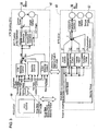
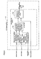
- FIG. 1 shows main components included in a steering mechanical train 32-37 and a traveling drive train 11, 17-20 of a vehicle 10 incorporating a steering system 30 according to the present invention.
- the vehicle 10 has an engine 11 mounted on the front side (left side as shown in Figure 1 ).
- a transaxle (not shown) integrated with the engine 11 is provided with a transmission, a transfer and a front differential, and the drive power of the engine 11 is transmitted to front drive shafts 13, 13 through the transmission and the front differential, so that front wheels 14, 14 are driven which correspond to steerable wheels in the present invention.
- the transfer of the transaxle has coupled thereto a front end portion of a front propeller shaft 18.
- a rear end portion of the front propeller shaft 18 is coupled to a front end portion of a rear propeller shaft 19 with a torque transmission device 20 interposed therebetween.
- a rear end portion of the rear propeller shaft 19 is coupled to a rear differential 17, and rear wheels 15 and 15 corresponding to non-steerable wheels in the present invention are attached to extreme ends of rear wheel drive shafts 16 and 16 which extend from the rear differential 17 in right and left directions.
- an input section is constituted at a portion coupled to the front propeller shaft 18, and an output section is constituted at a portion coupled to the rear propeller shaft 19.
- a clutch mechanism is provided between the input section and the output section.
- the torque transmission device 20 is controllable in dependence on a 4WD status determined by an ITCC-ECU (Electronic Control Unit for Intelligent Torque Control Coupling) 49 shown in Figure 3 .
- the 4WD status is data pertaining to the distribution of the traveling drive torques which are transmitted from the engine 11 to the front wheels 14 and the rear wheels 15.
- the 4WD status has been set so that for example, the torque distributions to the front wheels 14 and the rear wheels 15 become 100 : 0 during an ordinary traveling in which the vehicle travels straight ahead at a constant speed.
- the torque transmission device 20 (to be more exact, a clutch mechanism) is brought into an uncoupled state in dependence on the 4WD status, whereby the torque distribution from the engine 11 to the front wheels 14 becomes a hundred (100) percents, whereas the torque distribution to the engine 11 to the rear wheels 15 becomes zero (0) percent. That is, the drive mode is switched to the two-wheel drive mode in which the front wheels 14 only are driven.
- the ITCC-ECU 49 alters the 4WD status from a ratio of 100 : 0 to another ratio of 50 : 50. Then, in dependence on the 4WD status, the torque transmission device 20 is brought into a so-called "half clutch state" or "full coupling state". Thus, the traveling drive torque from the engine 11 is transmitted also to the rear wheels 15, and when the transmission device 20 is brought into the full coupling state, the torque transmission distributions from the engine 11 to the front wheels 14 and the rear wheels 15 become the ratio of 50 : 50, whereby the drive mode is switched to a full four-wheel drive state.
- the steering system 30 in the present embodiment is provided with an electric power steering device 32, an actuator 33 for the variable transmission ratio steering system, and an EPS-ECU (Electronic Control Unit for Electric Power Steering) 40 and a variable transmission ratio steering ECU (Electronic Control Unit) 41 for controlling these devices 32 and 33.
- EPS-ECU Electric Control Unit for Electric Power Steering
- ECU Electronic Control Unit
- the actuator 33 for the variable transmission ratio steering system is composed of a servomotor 38 (refer to Figure 3 ) and a reduction unit (not shown). Specifically, a stator of the servomotor 38 and a body of the reduction unit are integrated to constitute an input section of the actuator 33, whereas a rotor of the servomotor 38 and an input rotational section of the reduction unit are integrated to constitute an output section of the actuator 33.
- the input section of the actuator 33 has coupled thereto an input steering shaft 34 rotatable bodily with a steering handle 31. Further, the output section of the actuator 33 has coupled thereto an output steering shaft 35, whose extreme end is coupled to an input pinion gear of the electric power steering device 32.
- the stator and the rotor of the servomotor 38 are relatively rotated upon manipulation of the steering handle 31 to make the output section of the actuator 33 rotate relative to the input section of the same. Then, the angle which is made by adding the relative rotational amount (hereafter referred to as "ACT angle") of the actuator 33 to the rotational angle of the steering handle 31 is given to the input pinion gear (not shown) of the electric power steering device 32.
- ACT angle the angle which is made by adding the relative rotational amount
- a steering angle sensor 36 for detecting the steering angle of the steering handle 31 is provided at an intermediate portion of the input steering shaft 34. Further, a steering torque sensor 37 for detecting a steering torque applied to the steering handle 31 is provided at an extreme end portion of the output steering shaft 35.
- the aforementioned input pinion gear is rotatably provided to pass through a center axis portion of the torque sensor 37.
- the electric power steering device 32 is provided with a rack (not shown) extending in the transverse (i.e., left-right) direction of the vehicle 10. Tie rods 32R and 32R extending from opposite ends of the rack are coupled respectively to the front wheels 14 and 14.
- the electric power steering device 32 is further provided with a servomotor 39 (refer to Figure 3 ) whose center permits the rack to pass therethrough, and a rotor of the servomotor 39 and the rack are drivingly connected with each other through a ball screw mechanism (not shown). With this construction, the force which is required to manipulate the steering handle 31 in steering the front wheels 14 and 14 is assisted by the power of the servomotor 39.
- the variable transmission ratio steering ECU 41 executes a main program PG1 for variable transmission ratio steering ECU shown in Figure 2 , at a predetermined time interval, whereby the ACT angle of the actuator 33 is controlled as it is controlled by a control system which is represented by an upper block diagram in Figure 3 . That is, when the main program PG1 for variable transmission ratio steering ECU is executed, as shown in Figure 2 , the variable transmission ratio steering ECU 41 takes thereinto values from various sensors for vehicle speed, longitudinal G-force, lateral G-force, steering angle and the like (step S10) and then, takes thereinto the 4WD status from the ITCC-ECU 49 by way of a vehicle LAN (step S20).
- variable transmission ratio steering ECU 41 executes a variable transmission ratio steering control routine (step S30) to obtain an ACT command angle ⁇ 10 for variable transmission ratio steering control, executes a lead steering control routine (step S40) to obtain an ACT command angle ⁇ 20 for lead steering, and then, executes a stability control routine (step S50) to obtain an ACT command angle ⁇ 30 for stability control. Subsequently, the variable transmission ratio steering ECU 41 obtains an ACT command angle ⁇ 40 by making addition of these ACT command angles ⁇ 10, ⁇ 20 and ⁇ 30 (step S60) and then, performs a feed forward control and a feedback control so that the ACT angle of the actuator 33 follows the ACT command angle ⁇ 40 (step S70).
- the vehicle speed taken into the variable transmission ratio steering ECU 41 is obtained by averaging detection values of the vehicle speed sensors 14A and 15A provided for the front wheels 14 and the rear wheels 15 as shown in Figure 1 .
- the lateral G-force is a centrifugal force acting on the vehicle 10 during a cornering (i.e., turn at a corner), and the lateral G-force is detected by an acceleration sensor (not shown) provided on the vehicle 10. Further, the longitudinal G-force is also detected by the acceleration sensor provided on the vehicle 10, and based on the longitudinal G-force, it is judged whether the vehicle is traveling on an ascent or is traveling on a descent.
- the gradient of any slope can be inferred from the variations in the vehicle speed and the longitudinal G-force.
- the vehicle is inferred to being traveling on an ascent when a G-force directed rearward is being generated with the vehicle speed being kept constant.
- a transmission ratio decision map, a first transmission ratio alteration map and a second transmission ratio alteration map are stored in a ROM (Read-only Memory: not shown) provided in the variable transmission ratio steering ECU 41 (refer to Figure 5 ).
- Various vehicle speeds and various transmission ratios R1 are stored in the transmission ratio decision map in correlation with each other.
- the transmission ratio R1 in the present embodiment is calculated by the following expression.
- first transmission ratio alteration gain g10 is set to decrease as the torque distribution to the front wheels 14 determined by the 4WD status is decreased. More specifically, for example, where the torque distribution to the front wheels 14 is 100 percents, the first transmission ratio alteration gain g10 is set to indicate, e.g. "1".
- the first transmission ratio alteration gain g10 becomes smaller than "1" as the torque distribution to the front wheels 14 is decreased to be smaller than 100 percents and becomes to indicate a predetermined value less than "1" when the 4WD status is decreased to 50 percents to reach the full four-wheel drive state.
- a second transmission ratio alteration gain g11 which varies in dependence on whether the vehicle 10 is traveling on an ascent or on a descent is stored in a second transmission ratio alteration map.
- Values for ascent traveling of the second transmission ratio alteration gain g11 are set to be smaller than a value (e.g., "1") for horizontal traveling, whereas values for descent traveling of the second transmission ratio alteration gain g11 are set to be larger than the value for horizontal traveling.
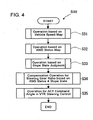
- variable transmission ratio steering ECU 41 executes the variable transmission ratio steering control routine (step S30) by reference to these maps. As shown in Figure 4 , the variable transmission ratio steering ECU 41 determines a transmission ratio R1 in dependence on the vehicle speed by reference to the transmission ratio decision map (step S31), determines a first transmission ratio alteration gain g10 in dependence on the 4WD status by reference to the first transmission ratio alteration map (step S32), and further determines a second transmission ratio alteration gain g11 in dependence on the longitudinal G-force (slope gradient) by reference to the second transmission ratio alteration map (step S33).
- a processing means at step S34 for compensating the transmission ratio R1 by multiplying the transmission ratio R1 with the first and second transmission ratio alteration gains g10 and g11 corresponds to transmission ratio alteration means in the present invention.
- the first transmission ratio alteration gain g10 becomes to be smaller.
- the steering gear is altered toward "quick" side when the vehicle drive mode approaches from the two-wheel drive mode toward the four-wheel drive mode.
- the second transmission ratio alteration gain g11 becomes to be smaller than that (e.g., "1") for horizontal traveling, in which case the compensation is performed at step S 34 to shift the steering gear toward "quick” side. To the contrary, the steering gear is shifted toward "slow” side during the descent traveling.
- the transmission ratio R1 which is determined in dependence on the vehicle speed by reference to the transmission ratio decision map is multiplied with the gains g10 and g11
- the transmission ratio decision map itself may be compensated by multiplying those parameters in the map with the gains g10 and g11, and the transmission ratio R1 may be determined in dependence on the vehicle speed by reference to the compensated transmission ratio decision map.
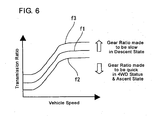
- Figure 6 shows a reference curve f1 which represents the transmission ratio decision map before compensation in the form of a graph.
- the reference curve f1 is shifted to a curve f2 at the lower side in the graph when the steering gear is shifted to the "quick” side and is shifted to another curve f3 at the upper side in the graph when the steering gear is shifted to the "slow” side.
- a responsiveness decision map, a first responsiveness alteration map and a second responsiveness alteration map are stored in the ROM (not shown) provided in the variable transmission ratio steering ECU 41 (refer to Figure 8 ).
- a lead steering gain g1 (hereafter referred to as "LS gain g1") is the gain in controlling the steered angle of the steerable wheels 14 relative to the manipulation amount of the steering handle 31, and various values of the lead steering gain g1 are set in the responsiveness decision map in correlation with various vehicle speeds.
- the first responsiveness alteration gain g20 is set to become larger as the torque distribution to the front wheels 14 determined by the 4WD status is decreased. More specifically, for example, where the torque distribution to the front wheels 14 is 100 percents, the first responsiveness alteration gain g20 is set to indicate, e.g. "1". Further, the first responsiveness alteration gain g20 becomes larger as the torque distribution to the front wheels 14 is decreased to be smaller than 100 percents and becomes to indicate a predetermined value larger than "1" when the 4WD status is decreased to 50 percents to reach the full four-wheel drive state.
- a second responsiveness alteration gain g21 which varies in dependence on whether the vehicle 10 is traveling on an ascent or on a descent is stored in the second responsiveness alteration map.
- Values for ascent traveling of the second responsiveness alteration gain g21 are set to be larger than a value (e.g., "1") for horizontal traveling, whereas values for descent traveling of the second responsiveness alteration gain g21 are set to be smaller than the value for horizontal traveling.
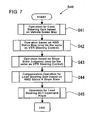
- variable transmission ratio steering ECU 41 executes the lead steering control routine (step S40) by reference to these maps. As shown in Figure 7 , the variable transmission ratio steering ECU 41 determines an LS gain g1 in dependence on the vehicle speed by reference to the responsiveness decision map (step S41), determines a first responsiveness alteration gain g20 in dependence on the 4WD status by reference to the first responsiveness alteration map (step S42), and further determines a second responsiveness alteration gain g21 in dependence on the longitudinal G-force by reference to the second responsiveness alteration map (step S43).
- a processing means at step S44 for compensating the LS gain g1 by multiplying the LS gain g1 with the first and second responsiveness alteration gains g20 and g21 corresponds to responsiveness alteration means in the present invention.
- the first responsiveness alteration gain g20 becomes larger.
- the responsiveness is altered to a higher side when the vehicle drive mode approaches from the two-wheel drive mode toward the four-wheel drive mode.
- the compensation at step S44 causes the responsiveness in the ascent traveling to be altered toward the higher side and also causes the responsiveness in the descent traveling to be altered toward a lower side.
- the LS gain g1 which is determined in dependence on the vehicle speed by reference to the responsiveness decision map is multiplied with the gains g20 and g21
- this responsiveness decision map itself may be compensated by multiplying those parameters in the map with the gains g20 and g21, and the LS gain g1 may be determined in dependence on the vehicle speed by reference to the compensated responsiveness decision map.
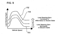
- Figure 9 shows a reference curve f10 which represents the responsiveness decision map before compensation in the form of a graph. The reference curve f10 is shifted to a curve f12 at the upper side in the graph when the responsiveness is altered toward the higher side and is shifted to another curve f11 at the lower side in the graph when the responsiveness is altered toward the lower side.
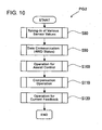
- the EPS-ECU 40 executes an EPS-ECU main program PG2 shown in Figure 10 at a predetermined time interval, whereby the assist force of the electric power steering device 32 is controlled as it is controlled by a control system which is represented by a lower block diagram in Figure 3 . That is, when the EPS-ECU main program PG2 is executed, as shown in Figure 10 , the EPS-ECU 40 takes thereinto values from various sensors for vehicle speed, longitudinal G-force, lateral G-force, steering angle and the like (step S80) and then, takes thereinto the 4WD status from the ITCC-ECU 49 by performing data communication by way of a vehicle LAN (step S90).
- the EPS-ECU 40 executes an assist control routine (step S100) to calculate a drive current command value I1. Then, the EPS-ECU 40 executes a routine for various compensation controls (torque inertia compensation control, handle return control and damping compensation control) to calculate drive current compensation command values 12, 13 and 14 (step S110). The EPS-ECU 40 then calculates an electric current command value I by adding the drive current compensation command values 12, 13 and 14 to the drive current command value I1 and performs a current feedback control so that the electric current applied to the servomotor 39 of the electric power steering device 32 coincides with the electric current command value I (step S120).
- an assist force decision map and first and second assist force alteration maps are stored in a ROM (not shown) provided in the EPS-ECU 40 (refer to Figure 12 ).
- Various values of the drive current command I1 to be applied to the servomotor 39 of the electric power steering device 32, and various values of the steering torque are stored in the assist force decision map in correlation with each other.
- Various values of a first assist force alteration gain g40 and various values of the 4WD status are stored in the first assist force alteration map in correlation with each other.
- the first assist force alteration gain g40 is set to become smaller as the torque distribution to the front wheels 14 determined by the 4WD status is decreased.
- the first assist force alteration gain g40 is set to indicate, e.g. "1". Further, the first assist force alteration gain g40 becomes smaller than "1" as the torque distribution to the front wheels 14 is decreased to be smaller than 100 percents and becomes to indicate a predetermined value smaller than "1" when the 4WD status is decreased to 50 percents to reach the full four-wheel drive state.
- a second assist force alteration gain g41 which varies in dependence on whether the vehicle 10 is in ascent traveling or descent traveling is stored in the second assist force alteration map.
- Values for ascent traveling of the second assist force alteration gain g41 are set to be smaller than a value (e.g., "1") for horizontal traveling, whereas values for descent traveling of the second assist force alteration gain g41 are set to be larger than the value for horizontal traveling.
- the EPS-ECU 40 executes the assist control routine (step S 100) by reference to these maps. As shown in Figure 11 , the EPS-ECU 40 determines a drive current command value I1 in dependence on the steering torque detected by the torque sensor 37 by reference to the assist force decision map (step S101), determines a first assist force alteration gain g40 in dependence on the 4WD status by reference to the first assist force alteration map (step S102), and further determines a second assist force alteration gain g41 in dependence on the longitudinal G-force by reference to the second assist force alteration map (step S103).
- step S104 the EPS-ECU 40 revises or compensates the drive current command value I1 by multiplying the drive current command value I1 with the gains g40 and g41 at an assist force compensation operation section 46 (refer to Figure 12 ) and thereafter leaves the assist control routine (step S100).
- a processing means at step S104 for compensating the drive current command value I1 by multiplying the same with the first and second assist force alteration gains g40 and g41 corresponds to assist force alteration means in the present invention.
- the first assist force alteration gain g40 becomes smaller.
- the assist force is altered to be increased when the vehicle drive mode approaches from the two-wheel drive mode toward the four-wheel drive mode.
- values for ascent traveling of the second assist force alteration gain g41 are set to be smaller than that (e.g., "1") for horizontal traveling, the compensation at step S104 causes the assist force in the ascent traveling to be altered toward a decreasing side and also causes the assist force in the descent traveling to be altered toward an increasing side.
- the drive current command value I1 is determined by multiplying with the gains g40 and g41 the drive current command value I1 which is determined in dependence on the steering torque by reference to the assist force decision map
- the assist force decision map itself may be compensated by multiplying those parameters in the map with the gains g40 and g41, and the drive current command value I1 may be determined in dependence on the steering torque by reference to the compensated assist force decision map.
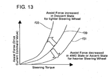
- Figure 13 shows a reference curve f20 which represents the assist force decision map before compensation in the form of a graph. The reference curve f20 is shifted to a curve f22 at the upper side in the graph when the assist force is altered to be increased and is shifted to another curve f21 at the lower side in the graph when the assist force is altered to be decreased.
- variable transmission ratio steering ECU 41 and the EPS-ECU 40 discriminate either of horizontal traveling, ascent traveling and descent traveling from one another. That is, the variable transmission ratio steering ECU 41 and the EPS-ECU 40 operates to judge whether the vehicle is traveling on a horizontal road, an ascent road or a descent road.
- variable transmission ratio steering ECU 41 alters the transmission ratio R1 to bring the steering gear into the "quick" side so that the steering resistance is made to be easily transmitted to the steering handle 31, while the EPS-ECU 40 lowers the assist force generated by the electric power steering device 32 to make the steering handle 31 heavier to manipulate. As a consequence, it can be realized to suppress the variation of the steering resistance which the driver receives on the steering handle 31.
- variable transmission ratio steering ECU 41 alters the transmission ratio R1 to bring the steering gear into the "slow" side so that the steering resistance is made hard to be transmitted to the steering handle 31, while the EPS-ECU 40 increases the assist force generated by the electric power steering device 32 to make the steering handle 31 lighter to manipulate.
- the EPS-ECU 40 increases the assist force generated by the electric power steering device 32 to make the steering handle 31 lighter to manipulate.
- variable transmission ratio steering ECU 41 alters the LS gain g1 to heighten the responsiveness. As a consequence, it can be realized to suppress the variation of the responsiveness the driver receives on the steering handle 31.
- the steering resistance (friction) that the front wheels 14 receive from the road surface increases, and this heightens the follow responsiveness of the front wheels 14 to the steering manipulation in dependence on the steering speed of the steering handle 31.
- the variable transmission ratio steering ECU 41 alters the LS gain g1 to lower the responsiveness. As a consequence, it can be realized to suppress the variation of the responsiveness the driver receives on the steering handle 31. In this manner, in the steering system 30 in the present embodiment, the steering resistance and the vehicle turn responsiveness to the steering manipulation can be kept constant regardless of whether ascent traveling or descent traveling, whereby the steering feeling can be kept stable.
- the ITCC-ECU 49 controls the torque transmission device 20 during straight-ahead traveling at a constant speed so that the torque distribution (4WD status) of the traveling drive torque to the front wheels 14 and the rear wheels 15 comes to the ratio of 100 : 0 to bring the drive mode into the two-wheel drive state in which the front wheels 14, 14 only are driven.
- the ITCC-ECU 49 shifts the drive mode toward the four-wheel drive mode by decreasing the torque distribution to the front wheels 14 from 100 percents and by increasing the torque distribution to the rear wheels 15 in order to suppress the slip of the front wheels 14.
- the ITCC-ECU 49 shifts the drive mode of the vehicle 10 toward the two-wheel drive mode by increasing the torque distribution to the front wheels 14.
- variable transmission ratio steering ECU 41 alters the transmission ratio R1 to make the steering gear "quick".
- the front wheels 14 become easily steerable by the steering manipulation of a lesser amount, whereby the variation of the steering feeling can be suppressed.
- the variable transmission ratio steering ECU 41 alters the transmission ratio R1 to make the steering gear "slow".
- a more amount of the steering manipulation is needed to steer the front wheels 14, whereby the variation of the steering feeling can be suppressed.
- the EPS-ECU 40 decreases the assist force when the torque distribution to the front wheel 14 is increased, whereby the variation of the steering feeling can be suppressed.
- the drive power given to the front wheels 14 is decreased to increase the steering resistance acting on the front wheels 14.
- the EPS-ECU 40 increases the assist force when the torque distribution to the front wheel 14 is decreased, whereby the variation of the steering feeling can be suppressed.
- variable transmission ratio steering ECU 41 alters the LS gain g1 to heighten the responsiveness, whereby the variation of the responsiveness which the driver feels on the steering handle 31 can be suppressed.
- the responsiveness in the turn of the vehicle 10 to the manipulation of the steering handle 31 rises where the torque distribution to the front wheels 14 is decreased.
- the variable transmission ratio steering ECU 41 alters the LS gain g1 to lower the responsiveness, whereby the variation of the responsiveness which the driver feels on the steering handle 31 can be suppressed.
- the steering system 30 in the present embodiment it can be realized to suppress the variation of the steering feeling which is caused by an increase or decrease in the torque distribution to the steerable wheels 14 as well as in dependence on the gradient in the ascent or descent traveling. Thus, it becomes possible to make the steering feeling stable.
- the present invention is not limited to the foregoing embodiment.
- the present invention encompasses the below-described embodiments within the technological scope thereof.
- the present invention can be practiced in various other forms than that described above insofar as it does not depart from the gist thereof.
- the transmission ratio R1 is altered by multiplying a transmission ratio R1 which is determined in dependence on the vehicle speed by reference to the transmission ratio decision map ( Figure 6 ), with a transmission ratio alteration gain g11 which is determined in dependence on the gradient in ascent traveling or descent traveling by reference to the transmission ratio alteration map.
- a transmission ratio alteration gain g11 which is determined in dependence on the gradient in ascent traveling or descent traveling by reference to the transmission ratio alteration map.
- the responsiveness of the vehicle turn to the steering manipulation lowers since the load onto the front wheels (steerable wheels) 14 decreases.
- the follow responsiveness of the steerable wheels 14 to the steering manipulation in ascent traveling is heightened compared with that in horizontal traveling.
- the responsiveness of the vehicle turn to the steering manipulation rises when the vehicle 10 gets into descent traveling.
- the follow responsiveness of the steerable wheels 14 to the steering manipulation in descent traveling is lowered compared with that in horizontal traveling, and thus, it can be realized to suppress the variation in the responsiveness to the vehicle turn. In this way, in the steering system 30, it becomes possible to make the steering feeling stable.
- the responsiveness is altered to increase the steering manipulation amount necessary to steer the steerable wheels 14 by multiplying a lead steering gain g1 which is determined in dependence on the vehicle speed by reference to the responsiveness decision map ( Figure 9 ), with a responsiveness alteration gain g21 which is determined in dependence on the gradient of the road surface by reference to the responsiveness alteration map.
- a lead steering gain g1 which is determined in dependence on the vehicle speed by reference to the responsiveness decision map ( Figure 9 )
- a responsiveness alteration gain g21 which is determined in dependence on the gradient of the road surface by reference to the responsiveness alteration map.
- the steering resistance which the steering handle 31 receives from the road surface decreases compared with that in horizontal traveling, thereby to make the steering manipulation lighter.
- the assist force for the steering manipulation in ascent traveling is decreased compared with that in horizontal traveling.
- the steering resistance which the steering handle 31 receives from the road surface increases thereby to make the steering manipulation heavier.
- the assist force for the steering manipulation in descent traveling is increased compared with that in horizontal traveling.
- it can be realized to suppress the variation of the steering feeling. In this way, it becomes possible to make the steering feeling stable in the steering system 30.
- the assist force is altered by multiplying a command value I1 of the assist force which is determined in dependence on the steering torque by reference to the assist force decision map ( Figure 13 ), with an assist force alteration gain g41 which is determined in dependence on the gradient in ascent traveling or descent traveling by reference to the assist force alteration map.
- the transmission ratio R1 is altered so that the manipulation amount of the steering handle 31 necessary to steer the steerable wheels 14 is decreased when the torque distribution to the steerable wheels 14 is increased.
- the steerable wheels 14 is enabled to be steered by a smaller steering manipulation, whereby it can be realized to suppress the variation of the steering feeling.
- the torque distribution to the steerable wheels 14 is decreased, the traveling direction becomes liable to be changed.
- the transmission ratio R1 is altered so that the manipulation amount of the steering handle 31 necessary to steer the steerable wheels 14 is increased when the torque distribution to the steerable wheels 14 is decreased.
- the steering manipulation comes to need much more steering manipulation to steer the steerable wheels 14, whereby it can be realized to suppress the variation of the steering feeling. In this way, it becomes possible to make the steering feeling stable in the steering system 30.
- the transmission ratio R1 is altered by multiplying a transmission ratio R1 which is determined in dependence on the vehicle speed by reference to the transmission ratio decision map ( Figure 6 ), with a transmission ratio alteration gain g10 which is determined in dependence on the torque distribution to the steerable wheels 14 and the non-steerable wheels 15 by reference to the transmission ratio alteration map.
- a transmission ratio alteration gain g10 which is determined in dependence on the torque distribution to the steerable wheels 14 and the non-steerable wheels 15 by reference to the transmission ratio alteration map.
- the responsiveness of the vehicle turn to the steering manipulation lowers when the torque distribution to the steerable wheels 14 is increased.
- the follow responsiveness of the steerable wheels 14 to the steering manipulation is heightened when the torque distribution to the steerable wheels 14 is increased.
- the responsiveness of the vehicle turn to the steering manipulation is suppressed to lower when the torque distribution to the steerable wheels 14 is decreased.
- the follow responsiveness of the steerable wheels 14 to the steering manipulation is lowered when the torque distribution to the steerable wheels 14 is decreased, whereby it can be realized to suppress the variation of the responsiveness in the vehicle turn. In this way, it becomes possible to make the steering feeling stable in the steering system 30.
- the responsiveness alteration means 41 c alters the responsiveness g1 by multiplying a lead steering gain g1 which is determined in dependence on the vehicle speed by reference to the responsiveness decision map ( Figure 9 ), with a responsiveness alteration gain g20 which is determined in dependence on the torque distribution to the steerable wheels 14 and the non-steerable wheels 15 by reference to the responsiveness alteration map.
- a lead steering gain g1 which is determined in dependence on the vehicle speed by reference to the responsiveness decision map ( Figure 9 )
- a responsiveness alteration gain g20 which is determined in dependence on the torque distribution to the steerable wheels 14 and the non-steerable wheels 15 by reference to the responsiveness alteration map.
- the drive power given to the steerable wheels 14 is increased to lower the steering resistance acting on the steering handle 31.
- the assist force is lowered when the torque distribution to the steerable wheels 14 is increased, whereby it can be realized to suppress the variation of the steering feeling.
- the drive power given to the steerable wheels 14 is also decreased to increase the steering resistance acting on the steering handle 31.
- the assist force is increased when the torque distribution to the steerable wheels 14 is decreased, whereby it can be realized to suppress the variation of the steering feeling. In this way, it becomes possible to make the steering feeling stable in the steering system 30.
- the assist force alteration means 46 alters the assist force 11 by multiplying a command value I1 of the assist force which is determined in dependence on the steering torque by reference to the assist force decision map ( Figure 13 ), with an assist force alteration gain g40 which is determined in dependence on the torque distribution to the steerable wheels 14 and the non-steerable wheels 15 by reference to the assist force alteration map.
- a command value I1 of the assist force which is determined in dependence on the steering torque by reference to the assist force decision map ( Figure 13 )
- an assist force alteration gain g40 which is determined in dependence on the torque distribution to the steerable wheels 14 and the non-steerable wheels 15 by reference to the assist force alteration map.
- the transmission ratio R1 is altered by multiplying a transmission ratio R1 which is determined in dependence on the vehicle speed by reference to the transmission ratio decision map ( Figure 6 ), with a first transmission ratio alteration gain g10 which is determined in dependence on the torque distribution to the steerable wheels 14 and the non-steerable wheels 15 by reference to the first transmission ratio alteration map.
- a transmission ratio R1 which is determined in dependence on the vehicle speed by reference to the transmission ratio decision map ( Figure 6 )
- a first transmission ratio alteration gain g10 which is determined in dependence on the torque distribution to the steerable wheels 14 and the non-steerable wheels 15 by reference to the first transmission ratio alteration map.
- the transmission ratio R1 is altered by multiplying the transmission ratio R1 which is determined in dependence on the vehicle speed by reference to the transmission ratio decision map ( Figure 6 ), with a second transmission ratio alteration gain g11 which is determined in dependence on the gradient in ascent traveling or descent traveling by reference to the second transmission ratio alteration map.
- a second transmission ratio alteration gain g11 which is determined in dependence on the gradient in ascent traveling or descent traveling by reference to the second transmission ratio alteration map.
- the responsiveness is altered by multiplying a lead steering gain g1 which is determined in dependence on the vehicle speed by reference to the responsiveness decision map ( Figure 9 ), with a first responsiveness alteration gain g20 which is determined in dependence on the torque distribution to the steerable wheels 14 and the non-steerable wheels 15 by reference to the first responsiveness alteration map.
- a lead steering gain g1 which is determined in dependence on the vehicle speed by reference to the responsiveness decision map ( Figure 9 )
- a first responsiveness alteration gain g20 which is determined in dependence on the torque distribution to the steerable wheels 14 and the non-steerable wheels 15 by reference to the first responsiveness alteration map.
- the responsiveness is altered by multiplying the lead steering gain g1 which is determined in dependence on the vehicle speed by reference to the responsiveness decision map ( Figure 9 ), with a second responsiveness alteration gain g21 which is determined in dependence on the angle of the gradient in ascent traveling or descent traveling by reference to the second responsiveness alteration map.
- the assist force I1 is altered by multiplying a command value I1 of the assist force which is determined in dependence on the steering torque by reference to the assist force decision map ( Figure 13 ), with a first assist force alteration gain g40 which is determined in dependence on the torque distribution to the steerable wheels 14 and the non-steerable wheels 15 by reference to the first assist force alteration map.
- a command value I1 of the assist force which is determined in dependence on the steering torque by reference to the assist force decision map ( Figure 13 )
- a first assist force alteration gain g40 which is determined in dependence on the torque distribution to the steerable wheels 14 and the non-steerable wheels 15 by reference to the first assist force alteration map.
- the assist force I1 is altered by multiplying the command value I1 of the assist force which is determined in dependence on the steering torque by reference to the assist force decision map ( Figure 13 ), with a second assist force alteration gain g41 which is determined in dependence on the gradient in ascent traveling or descent traveling by reference to the second assist force alteration map.
- a second assist force alteration gain g41 which is determined in dependence on the gradient in ascent traveling or descent traveling by reference to the second assist force alteration map.
- a transmission ratio R1 which is determined in dependence on the vehicle speed by reference to a transmission ratio decision map is multiplied with a first transmission ratio alteration gain g10 which is determined in dependence on the distribution of a traveling drive torque from an engine 11 to front wheels 14 and rear wheels 15, thereby to alter the ratio R1 of steering torque distribution from a steering handle 31 to the front wheels 14, whereby the variation of the steering feeling due to an increase or decrease in the distribution of the traveling drive torque to the front wheels 14 can be suppressed.
- the transmission ratio R1 is multiplied with a second transmission ratio alteration gain g11 which is determined in dependence on the gradient of the road surface by reference to a second transmission ratio alteration map, thereby to alter the transmission ratio R1, whereby the variation of the steering feeling due to the variation of the gradient can also be suppressed.
Landscapes
- Engineering & Computer Science (AREA)
- Chemical & Material Sciences (AREA)
- Combustion & Propulsion (AREA)
- Transportation (AREA)
- Mechanical Engineering (AREA)
- Steering Control In Accordance With Driving Conditions (AREA)
- Arrangement And Driving Of Transmission Devices (AREA)
- Power Steering Mechanism (AREA)
Applications Claiming Priority (2)
| Application Number | Priority Date | Filing Date | Title |
|---|---|---|---|
| JP2004112782A JP2005297622A (ja) | 2004-04-07 | 2004-04-07 | 操舵システム |
| JP2004112782 | 2004-04-07 |
Publications (3)
| Publication Number | Publication Date |
|---|---|
| EP1584540A2 EP1584540A2 (en) | 2005-10-12 |
| EP1584540A3 EP1584540A3 (en) | 2006-01-25 |
| EP1584540B1 true EP1584540B1 (en) | 2008-09-10 |
Family
ID=34909495
Family Applications (1)
| Application Number | Title | Priority Date | Filing Date |
|---|---|---|---|
| EP05007397A Expired - Lifetime EP1584540B1 (en) | 2004-04-07 | 2005-04-05 | Steering system for vehicle |
Country Status (5)
| Country | Link |
|---|---|
| US (1) | US7257474B2 (enExample) |
| EP (1) | EP1584540B1 (enExample) |
| JP (1) | JP2005297622A (enExample) |
| CN (1) | CN1680160A (enExample) |
| DE (1) | DE602005009597D1 (enExample) |
Families Citing this family (18)
| Publication number | Priority date | Publication date | Assignee | Title |
|---|---|---|---|---|
| US6587835B1 (en) * | 2000-02-09 | 2003-07-01 | G. Victor Treyz | Shopping assistance with handheld computing device |
| DE102004024458A1 (de) * | 2004-05-14 | 2005-12-08 | Continental Teves Ag & Co. Ohg | Verfahren zur Kompensation des Steigungseinflusses bei der Bestimmung einer Referenzgeschwindigkeit |
| JP4484036B2 (ja) * | 2004-05-21 | 2010-06-16 | 株式会社ジェイテクト | 車両の制御システム |
| JP4684658B2 (ja) * | 2005-01-11 | 2011-05-18 | 富士重工業株式会社 | 4輪駆動車のパワーステアリング装置 |
| JP4793008B2 (ja) * | 2006-02-09 | 2011-10-12 | 株式会社デンソー | 車両用操舵装置 |
| US7624836B2 (en) * | 2006-10-30 | 2009-12-01 | Caterpillar Inc. | Steering system having multiple strategies and variable deadzone |
| JP5613537B2 (ja) * | 2010-11-18 | 2014-10-22 | カヤバ工業株式会社 | 電動パワーステアリング装置の調整装置及び調整方法 |
| JP5591837B2 (ja) | 2012-01-25 | 2014-09-17 | 本田技研工業株式会社 | 車両及び操舵装置 |
| CN104108386B (zh) * | 2013-04-16 | 2019-06-25 | 博世汽车部件(苏州)有限公司 | 提高车辆行驶稳定性的方法和装置 |
| GB201316039D0 (en) * | 2013-09-09 | 2013-10-23 | Jaguar Land Rover Ltd | Vehicle control system and method |
| GB2518146A (en) * | 2013-09-10 | 2015-03-18 | Jaguar Land Rover Ltd | System and method for controlling configuration of vehicle power steering based on driveline operation |
| CN104554435B (zh) * | 2014-12-29 | 2017-06-30 | 长城汽车股份有限公司 | 汽车四驱控制方法及系统 |
| JP7060225B2 (ja) * | 2017-10-04 | 2022-04-26 | 株式会社大谷機械製作所 | 加工装置 |
| US10829153B1 (en) * | 2017-12-12 | 2020-11-10 | Nissan Motor Co., Ltd. | Vehicle steering control method and vehicle steering control device |
| US20200063401A1 (en) * | 2018-08-22 | 2020-02-27 | Deere & Company | Terrain Feed Forward Calculation |
| KR102808602B1 (ko) * | 2019-09-11 | 2025-05-20 | 에이치엘만도 주식회사 | 조향 제어 장치 및 그 방법, 그리고 조향 시스템 |
| JP7234968B2 (ja) * | 2020-02-17 | 2023-03-08 | トヨタ自動車株式会社 | 転舵装置 |
| CN112918553B (zh) * | 2021-03-12 | 2022-08-09 | 合肥工业大学 | 纵向坡道车辆自适应转向控制方法及装置 |
Family Cites Families (23)
| Publication number | Priority date | Publication date | Assignee | Title |
|---|---|---|---|---|
| JPS5414368B2 (enExample) * | 1973-03-15 | 1979-06-06 | ||
| US4658927A (en) * | 1984-11-19 | 1987-04-21 | Mazda Motor Corporation | Steering system for vehicle |
| JPH02227381A (ja) * | 1989-02-28 | 1990-09-10 | Mazda Motor Corp | 車両の後輪操舵とパワーステアリングの協調制御装置 |
| JPH03232032A (ja) | 1990-02-08 | 1991-10-16 | Toshiba Corp | メモリ制御装置 |
| JPH0443165A (ja) * | 1990-06-08 | 1992-02-13 | Mazda Motor Corp | 車両のパワーステアリング装置 |
| US5270930A (en) * | 1990-11-30 | 1993-12-14 | Mitsubishi Jidosha Kogyo Kabushiki Kaisha | Four wheel driving vehicle of a front/rear wheel differential operation limiting type |
| DE4201146C2 (de) * | 1991-01-18 | 2003-01-30 | Hitachi Ltd | Vorrichtung zur Steuerung des Kraftfahrzeugverhaltens |
| US6205374B1 (en) * | 1993-07-01 | 2001-03-20 | Mazda Motor Corporation | Vehicle characteristic change system and method |
| KR950028978A (ko) * | 1994-04-06 | 1995-11-22 | 전성원 | 급경사 및 급커브 주행시의 시프트패턴 제어장치 및 그 방법 |
| US6155377A (en) * | 1997-08-01 | 2000-12-05 | Honda Giken Kogyo Kabushiki Kaisha | Variable gear ratio steering system |
| JP3232032B2 (ja) | 1997-09-18 | 2001-11-26 | 本田技研工業株式会社 | 可変舵角比操舵装置 |
| JP3644343B2 (ja) | 2000-03-13 | 2005-04-27 | 豊田工機株式会社 | 電動パワーステアリング装置の制御装置 |
| JP2003127690A (ja) | 2001-10-30 | 2003-05-08 | Toyoda Mach Works Ltd | 4輪駆動車の駆動力配分方法および配分制御装置 |
| EP1355209A1 (en) | 2002-04-18 | 2003-10-22 | Ford Global Technologies, LLC | Vehicle control system |
| JP3970094B2 (ja) | 2002-05-27 | 2007-09-05 | 株式会社ジェイテクト | 操舵装置 |
| US7212896B2 (en) | 2002-05-29 | 2007-05-01 | Ford Global Technologies, Llc | Vehicle control |
| JP4459561B2 (ja) | 2002-09-04 | 2010-04-28 | 富士重工業株式会社 | コーナリングパワー制御装置およびコーナリングパワー制御方法 |
| JP2004106663A (ja) | 2002-09-17 | 2004-04-08 | Toyota Motor Corp | 総合駆動制御システムおよび総合駆動制御方法 |
| BRPI0410220A (pt) | 2003-05-13 | 2006-05-09 | Continental Teves Ag & Co Ohg | sistema de controle de dinámica de acionamento para veìculos |
| FR2857912B1 (fr) | 2003-07-23 | 2006-03-24 | Gie Psa Peugeot Citroen | Procede de reglage d'organes reglables d'un vehicule automobile pour adapter son comportement, systeme et support d'enregistrement pour mettre en oeuvre ce procede |
| JP2005112007A (ja) | 2003-10-02 | 2005-04-28 | Toyoda Mach Works Ltd | 車両の統合制御装置 |
| WO2005042294A1 (de) | 2003-11-04 | 2005-05-12 | Zf Friedrichshafen Ag | Verfahren zum beeinflussen von lastwechselreaktionen |
| US7073622B2 (en) * | 2004-06-15 | 2006-07-11 | Ford Global Technologies, Llc | On and off road steering ratios |
-
2004
- 2004-04-07 JP JP2004112782A patent/JP2005297622A/ja not_active Withdrawn
-
2005
- 2005-04-04 CN CNA2005100649198A patent/CN1680160A/zh active Pending
- 2005-04-04 US US11/097,131 patent/US7257474B2/en not_active Expired - Fee Related
- 2005-04-05 EP EP05007397A patent/EP1584540B1/en not_active Expired - Lifetime
- 2005-04-05 DE DE602005009597T patent/DE602005009597D1/de not_active Expired - Lifetime
Also Published As
| Publication number | Publication date |
|---|---|
| JP2005297622A (ja) | 2005-10-27 |
| CN1680160A (zh) | 2005-10-12 |
| EP1584540A2 (en) | 2005-10-12 |
| DE602005009597D1 (de) | 2008-10-23 |
| EP1584540A3 (en) | 2006-01-25 |
| US20050224277A1 (en) | 2005-10-13 |
| US7257474B2 (en) | 2007-08-14 |
Similar Documents
| Publication | Publication Date | Title |
|---|---|---|
| EP1584540B1 (en) | Steering system for vehicle | |
| EP1172278B1 (en) | Electric power steering system for vehicle | |
| CN113891827B (zh) | 车辆用转向装置 | |
| US6449542B1 (en) | Method for automatically controlling the lateral dynamics of a vehicle with front-axle steering | |
| US6556909B2 (en) | Lane keep control for vehicle | |
| US7740102B2 (en) | Steering control device for vehicle | |
| EP1808360B1 (en) | Electric power steering apparatus | |
| US6112845A (en) | Reactive steering control system | |
| US6360153B1 (en) | Co-operative control system for a vehicle | |
| EP2020363B1 (en) | Vehicle steering apparatus | |
| EP1892176A1 (en) | Steering system of vehicle | |
| US20040199316A1 (en) | Vehicle motion control method and vehicle motion control apparatus | |
| US20090182468A1 (en) | Understeer/Oversteer Correction for All Wheel Drive Vehicle | |
| EP1800994A1 (en) | Controller of electric power steering device of vehicle in which steered wheels are driven | |
| JP2006264392A (ja) | 反力装置の制御方法 | |
| EP1650072B1 (en) | Driving force distribution control apparatus of vehicle | |
| EP1700773B1 (en) | Variable steering ratio system and steering method | |
| EP2239179A1 (en) | Vehicle steering system | |
| JP4715472B2 (ja) | 車輌の操舵制御装置 | |
| JP5407407B2 (ja) | 車両舵角制御装置及び車両舵角制御方法 | |
| JP3731410B2 (ja) | 車輌の加速スリップ制御装置 | |
| JP4675655B2 (ja) | 反力装置の制御方法 | |
| JP4781726B2 (ja) | 車両の前後駆動力配分制御装置 | |
| JP4684754B2 (ja) | 車両の前後駆動力配分制御装置 | |
| JP2007113408A (ja) | 車両のエンジン出力制御装置 |
Legal Events
| Date | Code | Title | Description |
|---|---|---|---|
| PUAI | Public reference made under article 153(3) epc to a published international application that has entered the european phase |
Free format text: ORIGINAL CODE: 0009012 |
|
| AK | Designated contracting states |
Kind code of ref document: A2 Designated state(s): AT BE BG CH CY CZ DE DK EE ES FI FR GB GR HU IE IS IT LI LT LU MC NL PL PT RO SE SI SK TR |
|
| AX | Request for extension of the european patent |
Extension state: AL BA HR LV MK YU |
|
| PUAL | Search report despatched |
Free format text: ORIGINAL CODE: 0009013 |
|
| RIC1 | Information provided on ipc code assigned before grant |
Ipc: B62D 103/00 19900101ALN20050629BHEP Ipc: B62D 6/04 19850101ALI20051201BHEP Ipc: B62D 5/00 19680901AFI20050629BHEP Ipc: B62D 6/00 19850101ALI20051201BHEP Ipc: B62D 137/00 19900101ALN20050629BHEP |
|
| AK | Designated contracting states |
Kind code of ref document: A3 Designated state(s): AT BE BG CH CY CZ DE DK EE ES FI FR GB GR HU IE IS IT LI LT LU MC NL PL PT RO SE SI SK TR |
|
| AX | Request for extension of the european patent |
Extension state: AL BA HR LV MK YU |
|
| 17P | Request for examination filed |
Effective date: 20060703 |
|
| 17Q | First examination report despatched |
Effective date: 20060811 |
|
| AKX | Designation fees paid |
Designated state(s): DE FR GB |
|
| RAP1 | Party data changed (applicant data changed or rights of an application transferred) |
Owner name: JTEKT CORPORATION |
|
| RIN1 | Information on inventor provided before grant (corrected) |
Inventor name: MOMIYAMA, MINEKAZUJTEKT CORPORATION Inventor name: OHNO, AKIHIROJTEKT CORPORATION Inventor name: MURAKAMI, TSUYOSHIJTEKT CORPORATION Inventor name: KATO, HIROAKIJTEKT CORPORATION Inventor name: TAKEUCHI, SHINJIJTEKT CORPORATION |
|
| 17Q | First examination report despatched |
Effective date: 20060811 |
|
| GRAP | Despatch of communication of intention to grant a patent |
Free format text: ORIGINAL CODE: EPIDOSNIGR1 |
|
| RIC1 | Information provided on ipc code assigned before grant |
Ipc: B62D 5/00 20060101AFI20080305BHEP Ipc: B62D 6/04 20060101ALI20080305BHEP Ipc: B62D 6/00 20060101ALI20080305BHEP |
|
| GRAS | Grant fee paid |
Free format text: ORIGINAL CODE: EPIDOSNIGR3 |
|
| GRAA | (expected) grant |
Free format text: ORIGINAL CODE: 0009210 |
|
| AK | Designated contracting states |
Kind code of ref document: B1 Designated state(s): DE FR GB |
|
| REG | Reference to a national code |
Ref country code: GB Ref legal event code: FG4D |
|
| REF | Corresponds to: |
Ref document number: 602005009597 Country of ref document: DE Date of ref document: 20081023 Kind code of ref document: P |
|
| PLBE | No opposition filed within time limit |
Free format text: ORIGINAL CODE: 0009261 |
|
| STAA | Information on the status of an ep patent application or granted ep patent |
Free format text: STATUS: NO OPPOSITION FILED WITHIN TIME LIMIT |
|
| 26N | No opposition filed |
Effective date: 20090611 |
|
| GBPC | Gb: european patent ceased through non-payment of renewal fee |
Effective date: 20090405 |
|
| PG25 | Lapsed in a contracting state [announced via postgrant information from national office to epo] |
Ref country code: GB Free format text: LAPSE BECAUSE OF NON-PAYMENT OF DUE FEES Effective date: 20090405 |
|
| PGFP | Annual fee paid to national office [announced via postgrant information from national office to epo] |
Ref country code: DE Payment date: 20120419 Year of fee payment: 8 |
|
| PGFP | Annual fee paid to national office [announced via postgrant information from national office to epo] |
Ref country code: FR Payment date: 20120504 Year of fee payment: 8 |
|
| PG25 | Lapsed in a contracting state [announced via postgrant information from national office to epo] |
Ref country code: DE Free format text: LAPSE BECAUSE OF NON-PAYMENT OF DUE FEES Effective date: 20131101 |
|
| REG | Reference to a national code |
Ref country code: FR Ref legal event code: ST Effective date: 20131231 |
|
| REG | Reference to a national code |
Ref country code: DE Ref legal event code: R119 Ref document number: 602005009597 Country of ref document: DE Effective date: 20131101 |
|
| PG25 | Lapsed in a contracting state [announced via postgrant information from national office to epo] |
Ref country code: FR Free format text: LAPSE BECAUSE OF NON-PAYMENT OF DUE FEES Effective date: 20130430 |