EP1582615B1 - Nähmaschine - Google Patents
Nähmaschine Download PDFInfo
- Publication number
- EP1582615B1 EP1582615B1 EP05006698A EP05006698A EP1582615B1 EP 1582615 B1 EP1582615 B1 EP 1582615B1 EP 05006698 A EP05006698 A EP 05006698A EP 05006698 A EP05006698 A EP 05006698A EP 1582615 B1 EP1582615 B1 EP 1582615B1
- Authority
- EP
- European Patent Office
- Prior art keywords
- drive
- sewing machine
- thread
- driving lever
- machine according
- Prior art date
- Legal status (The legal status is an assumption and is not a legal conclusion. Google has not performed a legal analysis and makes no representation as to the accuracy of the status listed.)
- Expired - Lifetime
Links
Images



Classifications
-
- D—TEXTILES; PAPER
- D05—SEWING; EMBROIDERING; TUFTING
- D05B—SEWING
- D05B3/00—Sewing apparatus or machines with mechanism for lateral movement of the needle or the work or both for making ornamental pattern seams, for sewing buttonholes, for reinforcing openings or for fastening articles, e.g. buttons, by sewing
- D05B3/06—Sewing apparatus or machines with mechanism for lateral movement of the needle or the work or both for making ornamental pattern seams, for sewing buttonholes, for reinforcing openings or for fastening articles, e.g. buttons, by sewing for sewing buttonholes
-
- D—TEXTILES; PAPER
- D05—SEWING; EMBROIDERING; TUFTING
- D05B—SEWING
- D05B3/00—Sewing apparatus or machines with mechanism for lateral movement of the needle or the work or both for making ornamental pattern seams, for sewing buttonholes, for reinforcing openings or for fastening articles, e.g. buttons, by sewing
- D05B3/06—Sewing apparatus or machines with mechanism for lateral movement of the needle or the work or both for making ornamental pattern seams, for sewing buttonholes, for reinforcing openings or for fastening articles, e.g. buttons, by sewing for sewing buttonholes
- D05B3/08—Sewing apparatus or machines with mechanism for lateral movement of the needle or the work or both for making ornamental pattern seams, for sewing buttonholes, for reinforcing openings or for fastening articles, e.g. buttons, by sewing for sewing buttonholes for buttonholes with eyelet ends
-
- D—TEXTILES; PAPER
- D05—SEWING; EMBROIDERING; TUFTING
- D05B—SEWING
- D05B3/00—Sewing apparatus or machines with mechanism for lateral movement of the needle or the work or both for making ornamental pattern seams, for sewing buttonholes, for reinforcing openings or for fastening articles, e.g. buttons, by sewing
-
- D—TEXTILES; PAPER
- D05—SEWING; EMBROIDERING; TUFTING
- D05B—SEWING
- D05B65/00—Devices for severing the needle or lower thread
-
- D—TEXTILES; PAPER
- D05—SEWING; EMBROIDERING; TUFTING
- D05D—INDEXING SCHEME ASSOCIATED WITH SUBCLASSES D05B AND D05C, RELATING TO SEWING, EMBROIDERING AND TUFTING
- D05D2207/00—Use of special elements
- D05D2207/02—Pneumatic or hydraulic devices
Definitions
- the invention relates to a sewing machine according to the preamble of claim 1.
- an eye-buttonhole sewing machine which has a thread-cutting device with which both the needle thread and the looper thread and possibly also sewn to the looper thread Gimp thread will be cut off shortly.
- the thread-cutting device is designed in the manner of a pair of scissors with two mutually pivotable scissor parts. The shear parts are driven to close their cutting edges by means of a linear drive. The movement apart of the cutting edges under opening thereof takes place by the force of prestressed springs.
- the invention is therefore based on the object, a sewing machine of the generic type so that the reliability of the thread-cutting device is permanently guaranteed.
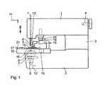
- an eye-buttonhole sewing machine C-shaped that is, it has an upper arm 1, a lower, cabinet-like base plate 2 and an interconnecting, approximately vertical stand 3 on.
- an arm shaft 4 is mounted in a conventional manner, which is driven by a drive motor, not shown.
- the drive of a vertical in the z direction movable needle bar with a needle 5 are derived in a conventional manner.
- a needle thread 6 is supplied from a needle thread supply, not shown.
- a gripper bearing 7 is arranged with grippers, not shown, in the base plate 2, which are rotatably driven about a vertical axis 8.
- the drive of the gripper bearing 7 takes place in the usual manner, as for example from the DE 198 07 771 A1 (corresponding U.S. Patent 6,095,066 ) is known.
- a stitch hole approach 9 is arranged in the base plate 2, pierces through which the needle 5.
- an xy-table 10 is arranged, which is thus a in two horizontal coordinate directions, namely the x-direction and the y-direction, displaceable cross slide.
- the xy-table 10 is formed in a conventional manner, as for example from the DE 198 07 771 A1 (corresponding U.S. Patent 6,095,066 ) is known.
- the drive of the xy-table 10 by means of an x-drive and a y-drive, in which it is positionable electric motors, so preferably preferably stepper motors, but also controllable DC motors. These drives are not shown.
- a two-piece support plate On the xy table 10, a two-piece support plate is arranged, which therefore consists of two partial support plates 11 and 11 '. These partial support plates 11 and 11 'are positively on the xy table 10, but removable held.
- a fabric clamp 13 which has a two-armed pivotable bearing lever 14.
- the pivotal drive of the bearing lever 14 and thus also the upper clamp plate 15 is effected by means of a drive located in the base plate 2, not shown, in detail from the EP 1 354 993 A2 (corresponding US 6,647,905 B2 ) is known.
- the upper clamp plate 15 is associated with a lower clamp plate 16 which is mounted on the part support plate 11. The space above the partial support plates 11, 11 'is covered by a cover 17, which of course leaves the lower clamp plate 16 free and adjoins it.
- a buttonhole cutter 18 is arranged in the y-direction behind the upper clamp plate 15, that is between this and the stand 3.
- the cutting device 18 has an arranged in the base plate 2, immovable in the z-direction cutting blade 19 and an arm 1 vertically above the cutting blade 19 arranged anvil 20 which is drivable in the z-direction down to the cutting blade 19 and back up.
- Such a configuration is for example from the DE 199 16 660 C1 (corresponding US 6,220,192 B1 ), to which reference may be made.
- the sewing material clamp 13 is inserted between the upper clamp plate 15 and the lower clamp plate 16 to be sewn fabric part 21.
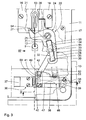
- a scissors thread cutting device 22 On the - in Fig. 2 shown on the right - part support plate 11 is designed as a scissors thread cutting device 22 is mounted. It has a lower first shearing part 23 and an upper second shaving part 24, which are fastened by means of a screw 25 acting as a joint on the sub-supporting plate 11, that is for fastening, adjustment and rotary connection for the shear parts 23, 24 on the part Support plate 11 is used.
- the shear parts 23, 24 have at their one end in each case a first cutting edge 26 and a second cutting edge 27, which can be moved against each other for cutting.
- both arms 28, 29 of different lengths On the sides facing away from the two cutting edges 26, 27, ie on the sides of the scissor parts 23, 24 lying beyond the joint 25, are two arms 28, 29 of different lengths, namely a first, longer arm 28 on the first shearing part 23 and a short second arm 29 on the second shearing part 24, formed. Both arms of different length 28, 29 have two mutually facing, so towards each other open, formed as a so-called throat recesses 30, 31, namely a first recess 30 and a second recess 31, on. In these recesses 30, 31 engages a two-armed actuating lever 32 which is mounted approximately in its center by means of a part of the support plate 11 passing through the shaft 33 at the latter.
- the double-armed actuating lever 32 has a first lever arm 34, which engages with its end in a form-fitting manner in the first recess 30 of the first shearing part 23. He further has a second lever arm 34 which engages positively with its end in the second recess 31 of the second shearing part 24.
- the double-armed actuating lever 32 is pivotally driven by means of a linear drive 36 formed by a pneumatically actuated piston-cylinder drive.
- This drive 36 has a relative to the x-y table 10 fixed cylinder 37, the piston rod 38 is linearly movable with a corresponding pneumatic actuation of the cylinder 37.
- the pneumatic actuation of the cylinder 37 via a controllable by the control of the sewing machine, not shown solenoid valve, wherein the compressed air supply from a compressed air source, also not shown here takes place.
- the piston rod 38 is guided near its outer free end by means of a guide bearing 39.
- a drive block 40 is fixed, which has a transverse to the direction of movement of the piston rod 38 and vertically extending guide link 41.
- one end of a drive lever 42 is guided by means of a guide roller 43.
- the drive lever 42 by means of a clamping connection 44 rotatably connected to the shaft 33.
- the drive block 40 is slidably supported on a sliding plate 45 arranged below the piston rod 38.
- a positional fuse 46 is provided for the drive lever 42, the drive lever 42 in the in the Fig. 3 and 5 illustrated opening position or rest position of the thread-cutting device 22 holds when the part-support plate 11 together with the thread-cutting device 22 is lifted from the xy-table 10.
- This position assurance 46 has a leaf spring designed as safety tab 47, one end of which in the vicinity of the guide bearing 39 by means of a screw 48 on the underside of the sub-support plate 11, ie on the linear drive 36 side facing attached is.
- the tab 47 thus extends over the entire actuating travel of the drive block 40 between the open position or rest position of the thread cutting device 22 and the dot-dash line position of the drive lever 42 in the closed position or working position of the thread cutting device 22
- Lever 42 has on its side facing away from the guide roller 43, the part of the support plate 11 side facing a cylindrical securing pin 49.
- On the drive block 40 a formed by a pin with a half-round head release member 50 is mounted, which abuts in the xy table 10 inserted part support plate 11 against the securing tab 47 and pushes upwards in the direction of the part-support plate 11, such as it in Fig. 5 is shown.
- the securing lug 47 has a projection 51 which lies in the displacement path of the guide roller 43 and which has a securing surface 52, behind which the securing pin 49 in the in Fig. 3 shown in rest position of the drive 48, which thus corresponds to the open position of the thread cutting device 22, can put. If - as already mentioned - the partial support plate 11 is lifted with the thread-cutting device 22 from the xy-table 10, then the securing tab 47 is disengaged from the release member 50 so that the securing tab 47 is deflected down and the securing pin 49 passes behind the securing surface 52 of the securing tab 47. An unintentional pivoting or or adjustment of the drive lever 42 is thus excluded with disassembled thread cutting device 22. When the sub-tray 11 is again inserted into the xy table 10 with the thread cutter 22, the guide roller 43 is forcibly inserted into the guide slot 41 of the drive block 40; Malfunction and the resulting damage to the thread cutter 22 are thus excluded.
- an end portion 54 of the looper thread 12 extends from the stitch hole approach 9 to the eye buttonhole seam 53.
- the thread cutting device 22 out of her in Fig. 3 open position shown in her in Fig. 7 shown closed position, whereby the end portion 54 of the looper thread 12 immediately adjacent to the eye-buttonhole seam 53 is cut.
- the piston rod 38 is again inserted into the cylinder 37, whereby the thread cutting device 22 is opened. For reasons of clarity, only the cutting of the looper thread 12 is shown.
Landscapes
- Engineering & Computer Science (AREA)
- Textile Engineering (AREA)
- Sewing Machines And Sewing (AREA)
Description
- Die Erfindung betrifft eine Nähmaschine nach dem Oberbegriff des Anspruches 1.
- Aus dem Prospekt der Dürkopp Adler AG "Doppelkettenstich-Augenknopflochautomat mit CNC-Schrittmotortechnik 579/589" ist eine AugenKnopfloch-Nähmaschine bekannt, die eine Faden-Schneideinrichtung aufweist, mit der sowohl der Nadelfaden als auch der Greiferfaden und gegebenenfalls auch ein mit dem Greiferfaden vernähter Gimpenfaden kurz abgeschnitten werden. Die Faden-Schneideinrichtung ist nach Art einer Schere mit zwei gegeneinander verschwenkbaren Scherenteilen ausgebildet. Der Antrieb der Scherenteile zum Schließen ihrer Schneiden erfolgt durch einen Linear-Antrieb. Die Auseinanderbewegung der Schneiden unter Öffnen derselben erfolgt durch die Kraft von vorgespannten Federn. Beim Fadenschneiden fällt ein feiner Staub an, der die Bewegbarkeit der Scherenteile gegeneinander so stark beeinträchtigen kann, dass das Öffnen der Schneiden mittels der Federn nicht mehr gewährleistet ist. Hierdurch bedingt kann es zu einer Kollision zwischen der Nadel und einem Scherenteil und damit zum Nadelbruch und weiteren Beschädigungen der Nähmaschine kommen. Diese Schwergängigkeit mit den geschilderten Folgen kann auch eintreten, wenn die beiden Scherenteile beim Justieren zu stark gegeneinander verspannt werden.
- Aus der
DE 100 63 003 A1 ist eine Nähmaschine nach dem Oberbegriff des Anspruchs 1 bekannt, bei der Obermesser und Untermesser derart scherenartig miteinander gekoppelt sind, dass das Öffnen und Schließen über den Antrieb erfolgt. Die Art der Kopplung ist nicht betriebssicher. - Der Erfindung liegt daher die Aufgabe zu Grunde, eine Nähmaschine der gattungsgemäßen Art so weiterzubilden, dass die Betriebssicherheit der Faden-Schneideinrichtung dauerhaft gewährleistet ist.
- Diese Aufgabe wird erfindungsgemäß durch das Merkmal im Kennzeichnungsteil des Anspruches 1 gelöst. Durch die erfindungsgemäßen Maßnahmen ist sichergestellt, dass die Faden-Schneideinrichtung nicht nur zwangsweise zum Fadenschneiden geschlossen, sondern durch den Antrieb anschließend zwangsweise auch wieder geöffnet wird, da eine einfache Zwangskopplung zwischen den beiden Scherenteilen erreicht wird.
- Durch die Weiterbildung nach Anspruch 2 und 3 wird in einfacher Weise ermöglicht, einen Linear-Antrieb zur Erzeugung der Schwenkbewegung der Scherenteile einzusetzen, sodass beispielsweise ein pneumatisch beaufschlagbarer Kolben-Zylinder-Antrieb eingesetzt werden kann.
- Um eine einfache Demontage der Faden-Schneideinrichtung von der Nähmaschine zu ermöglichen, ist die Weiterbildung nach Anspruch 4 vorgesehen, wobei die weiteren vorteilhaften Maßnahmen nach den Ansprüchen 5 bis 7 sicherstellen, dass die Faden-Schneideinrichtung auch in demontiertem Zustand eine definierte Endlage einnimmt, sodass beim Wiedereinsetzen in die Nähmaschine Fehlpositionierungen vermieden werden, die zu einer Beschädigung der Nähmaschine führen könnten.
- Weitere Einzelheiten der Erfindung ergeben sich aus der nachfolgenden Beschreibung eines Ausführungsbeispiels an Hand der Zeichnung. Es zeigt
- Fig. 1
- eine Seiten-Längs-Ansicht einer Augen-Knopfloch-Nähmaschine, wobei ein x-y-Tisch gegenüber einer Nadel in einer Stellung gezeigt ist, in der ein zu benähendes Nähgutteil eingelegt werden kann,
- Fig. 2
- eine vergrößerte Ansicht auf einen geöffneten Bereich des x-y-Tisches entsprechend dem Sichtpfeil II in
Fig. 1 , wobei die Darstellung um 90° entgegen dem Uhrzeigersinn gedreht ist und wobei eine Faden-Schneideinrichtung in ihrer Ruhelage dargestellt ist, - Fig. 3
- eine vergrößerte, teilweise aufgebrochene Teil-Darstellung aus
Fig. 2 , - Fig. 4
- eine Seitenansicht der Faden-Schneideinrichtung entsprechend dem Sichtpfeil IV in
Fig. 3 , - Fig. 5
- eine Schnittdarstellung in vergrößertem Maßstab entsprechend der Schnittlinie V-V in
Fig. 3 , wobei die Faden-Schneideinrichtung in ihrer Ruhelage dargestellt ist, - Fig. 6
- eine Teil-Darstellung aus
Fig. 5 mit der Faden-Schneideinrichtung in vom x-y-Tisch abgenommenen Zustand, in dem eine Lage-Sicherung die Faden-Schneidein-richtung in ihrer Ruhelage sichert und - Fig. 7
- eine Draufsicht auf die Faden-Schneideinrichtung in geschlossenem Zustand nach Durchtrennen eines Fadens.
- Wie
Fig. 1 entnehmbar ist, ist eine Augen-Knopfloch-Nähmaschine C-förmig ausgebildet, d. h. sie weist einen oberen Arm 1, eine untere, gehäuseartig ausgebildete Grundplatte 2 und einen beide verbindenden, etwa vertikalen Ständer 3 auf. Im Arm 1 ist in üblicher Weise eine Armwelle 4 gelagert, die von einem nicht dargestellten Antriebsmotor antreibbar ist. Von der Armwelle 4 werden in üblicher Weise der Antrieb einer vertikalen in z-Richtung verschiebbaren Nadelstange mit einer Nadel 5 abgeleitet. Mittels der Nadel 5 wird ein Nadelfaden 6 von einem nicht dargestellten Nadelfaden-Vorrat zugeführt. Unterhalb der Nadelstange mit Nadel 5 ist in der Grundplatte 2 ein Greiferlager 7 mit nicht dargestellten Greifern angeordnet, die um eine vertikale Achse 8 drehantreibbar sind. Der Antrieb des Greiferlagers 7 erfolgt in üblicher Weise, wie es beispielsweise aus derDE 198 07 771 A1 (entsprechendUS-PS 6,095,066 ) bekannt ist. Oberhalb des Greiferlagers 7 ist in der Grundplatte 2 ein Stichloch-Ansatz 9 angeordnet, durch den die Nadel 5 einsticht. - Auf der Grundplatte 2 ist ein x-y-Tisch 10 angeordnet, bei dem es sich also um einen in zwei horizontalen Koordinatenrichtungen, nämlich der x-Richtung und der y-Richtung, verschiebbaren Kreuzschlitten handelt. Der x-y-Tisch 10 ist in üblicher Weise ausgebildet, wie es beispielsweise aus der
DE 198 07 771 A1 (entsprechendUS-PS 6,095,066 ) bekannt ist. Der Antrieb des x-y-Tisches 10 erfolgt mittels eines x-Antriebes und eines y-Antriebes, bei dem es sich um positionierbare Elektromotoren, in der Regel also bevorzugt Schrittmotoren, aber auch regelbare Gleichstrommotoren handelt. Diese Antriebe sind nicht dargestellt. - Auf dem x-y-Tisch 10 ist eine zweiteilige Tragplatte angeordnet, die also aus zwei Teil-Tragplatten 11 und 11' besteht. Diese Teil-Tragplatten 11 bzw. 11' sind auf dem x-y-Tisch 10 formschlüssig, jedoch abnehmbar gehalten. Die Teil-Tragplatten 11, 11' überdecken das Greiferlager 7 und müssen zum Einziehen eines Greiferfadens 12 abgenommen werden, der von einem nicht dargestellten Greiferfaden-Vorrat zugeführt wird. Es kann auch ein Gimpenfaden zugeführt werden, was nicht gesondert dargestellt ist, da es allgemein bekannt ist.
- Es ist eine Nähgut-Klammer 13 vorgesehen, die einen doppelarmigen schwenkbaren Lagerhebel 14 aufweist. Der Lagerhebel 14 trägt an seinem freien Ende eine obere Klammerplatte 15. Der Schwenkantrieb des Lagerhebels 14 und damit auch der oberen Klammerplatte 15 erfolgt mittels eines in der Grundplatte 2 befindlichen nicht dargestellten Antriebs, der im Einzelnen aus der
EP 1 354 993 A2 (entsprechendUS 6,647,905 B2 ) bekannt ist. Der oberen Klammerplatte 15 ist eine untere Klammerplatte 16 zugeordnet, die auf der Teil-Tragplatte 11 befestigt ist. Der Raum oberhalb der Teil-Tragplatten 11, 11' ist durch eine Abdeckung 17 abgedeckt, die selbstverständlich die untere Klammerplatte 16 frei lässt und an diese anschließt. - In y-Richtung hinter der oberen Klammerplatte 15, also zwischen dieser und dem Ständer 3 ist eine Knopfloch-Schneideinrichtung 18 angeordnet. Die Schneideinrichtung 18 weist ein in der Grundplatte 2 angeordnetes, in z-Richtung unverschiebbares Schneidmesser 19 und einen im Arm 1 senkrecht über dem Schneidmesser 19 angeordneten Amboss 20 auf, der in z-Richtung nach unten zum Schneidmesser 19 und zurück nach oben antreibbar ist. Eine derartige Ausgestaltung ist beispielsweise aus der
DE 199 16 660 C1 (entsprechendUS 6,220,192 B1 ) bekannt, worauf verwiesen werden kann. In die Nähgut-Klammer 13 ist zwischen die obere Klammerplatte 15 und die untere Klammerplatte 16 ein zu nähendes Nähgutteil 21 eingelegt. - Auf der - in
Fig. 2 rechts dargestellten - Teil-Tragplatte 11 ist eine als Schere ausgebildete Faden-Schneideinrichtung 22 angebracht. Sie weist ein unteres erstes Scherenteil 23 und ein oberes zweites Scherenteil 24 auf, die mittels einer als Gelenk 25 dienenden Schraube auf der Teil-Tragplatte 11 befestigt sind, die also zur Befestigung, Einstellung und Drehverbindung für die Scherenteile 23, 24 auf der Teil-Tragplatte 11 dient. Die Scherenteile 23, 24 weisen an ihrem einen Ende jeweils eine erste Schneide 26 bzw. eine zweite Schneide 27 auf, die zum Schneiden gegeneinander bewegt werden können. - An den den beiden Schneiden 26, 27 abgewandten Seiten, also auf den - von den Schneiden 26, 27 her gesehen - jenseits des Gelenks 25 liegenden Seiten der Scherenteile 23, 24, sind zwei unterschiedlich lange Arme 28, 29, nämlich ein erster längerer Arm 28 am ersten Scherenteil 23 und ein kurzer zweiter Arm 29 am zweiten Scherenteil 24, ausgebildet. Beide unterschiedlich langen Arme 28, 29 weisen zwei einander zugewandte, also zueinander hin offene, als sogenannte Rachen ausgebildete Ausnehmungen 30, 31, nämlich eine erste Ausnehmung 30 und eine zweite Ausnehmung 31, auf. In diese Ausnehmungen 30, 31 greift ein doppelarmiger Betätigungs-Hebel 32 ein, der etwa in seiner Mitte mittels einer die Teil-Tragplatte 11 durchsetzenden Welle 33 an letzterer gelagert ist. Der doppelarmige Betätigungs-Hebel 32 weist einen ersten Hebelarm 34 auf, der mit seinem Ende formschlüssig in die erste Ausnehmung 30 des ersten Scherenteils 23 eingreift. Er weist weiterhin einen zweiten Hebelarm 34 auf, der mit seinem Ende formschlüssig in die zweite Ausnehmung 31 des zweiten Scherenteils 24 eingreift. Bei Verschwenkungen des BetätigungsHebels 32 um seine Welle 33 werden die Scherenteile 23, 24 zwangsweise relativ zueinander um ihr Gelenk 25 verschwenkt, sodass ein Schließen der Faden-Schneideinrichtung 22 zum Schneiden eines Fadens und das Öffnen der Faden-Schneideinrichtung 22 jeweils zwangsgeführt erfolgt.
- Der doppelarmige Betätigungs-Hebel 32 ist mittels eines durch einen pneumatisch beaufschlagbaren Kolben-Zylinder-Antrieb gebildeten Linear-Antrieb 36 schwenkantreibbar. Dieser Antrieb 36 weist einen gegenüber dem x-y-Tisch 10 ortsfesten Zylinder 37 auf, dessen Kolbenstange 38 bei entsprechender pneumatischer Beaufschlagung des Zylinders 37 linear bewegbar ist. Die pneumatische Beaufschlagung des Zylinders 37 erfolgt über ein von der Steuerung der Nähmaschine ansteuerbares, nicht dargestelltes Magnetventil, wobei die Druckluftversorgung von einer ebenfalls nicht dargestellten Druckluftquelle her erfolgt.
- Die Kolbenstange 38 ist in der Nähe ihres äußeren freien Endes mittels eines Führungslagers 39 geführt. Auf der Kolbenstange 38 ist ein Antriebsblock 40 befestigt, der eine quer zur Bewegungsrichtung der Kolbenstange 38 und vertikal verlaufende Führungs-Kulisse 41 aufweist. In dieser Führungs-Kulisse 41 ist ein Ende eines Antriebs-Hebels 42 mittels einer Führungsrolle 43 geführt. An seinem anderen Ende ist der Antriebs-Hebel 42 mittels einer Klemm-Verbindung 44 drehfest mit der Welle 33 verbunden. Der Antriebsblock 40 ist auf einer unterhalb der Kolbenstange 38 angeordneten Gleitplatte 45 verschiebbar abgestützt. Wenn die Kolbenstange 38 aus dem Zylinder 37 - in
Fig. 3 und5 nach rechts - ausgefahren wird, dann wird der Antriebsblock 40 mit dem Antriebs-Hebel 42 aus der inFig. 3 ausgezogen dargestellten Position in die strichpunktiert angedeutete Position verfahren und hierdurch der Betätigungs-Hebel 32 im Gegenuhrzeigersinn verschwenkt, wodurch die die Faden-Schneideinrichtung 22 bildende Schere geschlossen, also in ihre Arbeitsstellung verbracht wird, wie es inFig. 7 dargestellt ist. - An der die Faden-Schneideinrichtung 22 tragenden Teil-Tragplatte 11 ist eine Lage-Sicherung 46 für den Antriebs-Hebel 42 vorgesehen, die den Antriebs-Hebel 42 in der in den
Fig. 3 und5 dargestellten ÖffnungsStellung bzw. Ruhelage der Faden-Schneideinrichtung 22 hält, wenn die Teil-Tragplatte 11 samt Faden-Schneideinrichtung 22 vom x-y-Tisch 10 abgehoben wird. Diese Lage-Sicherung 46 weist eine als Blattfeder ausgebildete Sicherungs-Lasche 47 auf, deren eines Ende in der Nähe des Führungslagers 39 mittels einer Schraube 48 an der Unterseite der Teil-Tragplatte 11, also auf deren dem Linear-Antrieb 36 zugewandten Seite, befestigt ist. Die Lasche 47 erstreckt sich also über den gesamten Betätigungsweg des Antriebsblocks 40 zwischen der ausgezogen dargestellten Öffnungsstellung bzw. Ruhelage der Faden-Schneideinrichtung 22 und der strichpunktiert angedeuteten Stellung des Antriebs-Hebels 42 bei der Schließstellung bzw. Arbeitsstellung der Faden-Schneideinrichtung 22. Der Antriebs-Hebel 42 weist auf seiner der Führungs-Rolle 43 abgewandten, der Teil-Tragplatte 11 zugewandten Seite einen zylindrischen Sicherungs-Zapfen 49 auf. Auf dem Antriebsblock 40 ist ein durch einen Stift mit Halbrundkopf gebildetes Entsicherungsteil 50 angebracht, das bei in den x-y-Tisch 10 eingesetzter Teil-Tragplatte 11 gegen die Sicherungs-Lasche 47 anliegt und diese nach oben in Richtung zur Teil-Tragplatte 11 drückt, wie es inFig. 5 dargestellt ist. Wenn dagegen bei aus dem x-y-Tisch 10 herausgenommener Trag-Platte 11 das Entsicherungsteil 50 nicht mehr an der Sicherungs-Lasche 47 anliegt, dann ist diese - wieFig. 6 erkennen lässt - auf Grund ihrer Ausgestaltung als Blattfeder elastisch nach unten ausgelenkt. - Die Sicherungs-Lasche 47 weist einen Vorsprung 51 auf, der im Verschiebeweg der Führungsrolle 43 liegt und der eine Sicherungsfläche 52 aufweist, hinter die sich der Sicherungs-Zapfen 49 in der in
Fig. 3 ausgezogen dargestellten Ruhelage des Antriebs 48, die also der Öffnungsstellung der Faden-Schneideinrichtung 22 entspricht, legen kann. Wenn - wie bereits erwähnt - die Teil-Tragplatte 11 mit der Faden-Schneideinrichtung 22 vom x-y-Tisch 10 abgehoben wird, dann kommt die Sicherungs-Lasche 47 außer Eingriff mit dem Entsicherungsteil 50, sodass die Sicherungs-Lasche 47 nach unten ausgelenkt wird und der Sicherungs-Zapfen 49 hinter die Sicherungs-Fläche 52 der Sicherungs-Lasche 47 gelangt. Ein unbeabsichtigtes Verschwenken oder bzw. Verstellen des Antriebs-Hebels 42 ist damit bei demontierter Faden-Schneideinrichtung 22 ausgeschlossen. Wenn die Teil-Tragplatte 11 mit der Faden-Schneideinrichtung 22 wieder in den x-y-Tisch 10 eingesetzt wird, wird damit zwangsweise die Führungsrolle 43 in die Führungskulisse 41 des Antriebsblocks 40 eingesetzt; Fehlfunktionen und die daraus resultierenden Beschädigungen der Faden-Schneideinrichtung 22 sind damit ausgeschlossen. - Nach dem Nähen einer Augen-Knopfloch-Naht 53 in dem Nähgutteil 21 verläuft ein Endabschnitt 54 des Greiferfadens 12 von dem Stichloch-Ansatz 9 zur Augen-Knopfloch-Naht 53. Durch die bereits geschilderte Betätigung des Linear-Antriebs 36 wird die Faden-Schneideinrichtung 22 aus ihrer in
Fig. 3 geöffnet dargestellten Stellung in ihre inFig. 7 geschlossen dargestellte Position verbracht, wodurch der Endabschnitt 54 des Greiferfadens 12 unmittelbar benachbart zur Augen-Knopfloch-Naht 53 durchgeschnitten wird. Im Anschluss daran wird die Kolbenstange 38 wieder in den Zylinder 37 eingeführt, wodurch die Faden-Schneideinrichtung 22 geöffnet wird. Aus Gründen der Übersichtlichkeit ist nur das Schneiden des Greiferfadens 12 dargestellt.
Claims (8)
- Nähmaschine zum Erzeugen einer Naht (53) mit einem Endabschnitt (54) eines Greiferfadens (12),- mit einem Arm (1),- mit einer mittels einer am Arm (1) gelagerten Armwelle (4) in einer z-Richtung antreibbaren Nadel (5) zur Führung eines Nadelfadens (6),- mit einer Grundplatte (2),- mit einem auf der Grundplatte (2) in einer x-Richtung und einer y-Richtung verschiebbaren x-y-Tisch (10),- mit einer auf dem x-y-Tisch (10) angeordneten Nähgut-Klammer (13),- mit einem an der Grundplatte (2) angeordneten, drehantreibbaren Greiferlager (7) mit einem unterhalb der Nadel (5) angeordneten Stichloch-Ansatz (9) zur Zuführung des Greiferfadens (12),- mit einer am x-y-Tisch (10) angeordneten, nach Art einer Schere ausgebildeten Faden-Schneideinrichtung (22), die- ein erstes Scherenteil (23) mit einer ersten Schneide (26)
und- ein zweites Scherenteil (24) mit einer zweiten Schneide (27) aufweist, die gegeneinander verschwenkbar zum Schließen und Öffnen der Schneiden (26, 27) gelagert sind,- mit einem Antrieb (36) zur Verschwenkung des ersten und zweiten Scherenteils (23, 24) gegeneinander zur Ausführung einer Schneidbewegung der ersten und zweiten Schneide (26, 27) unter Schließen der Schneiden (26, 27),- wobei zwischen dem Antrieb (36) und dem ersten Scherenteil (23)
und dem zweiten Scherenteil (24) eine Zwangskopplung derart vorgesehen ist, dass auch das Öffnen der Schneiden (26, 27) durch den Antrieb (36) erfolgt,
dadurch gekennzeichnet,
dass die Scherenteile (23, 24) mittels eines schwenkbar gelagerten Betätigungs-Hebels (32) miteinander gekoppelt sind, der mit dem Antrieb (36) schwenkantreibbar verbunden ist und
dass der Betätigungs-Hebel (32) doppelarmig ausgebildet ist und mit seinen Enden formschlüssig in einander zugewandte Ausnehmungen (30, 31) der Scherenteile (23, 24) eingreift. - Nähmaschine nach Anspruch 1, dadurch gekennzeichnet,
dass der Antrieb als Linear-Antrieb (36) ausgebildet ist, der mittels eines Antriebs-Hebels (42) mit dem Betätigungs-Hebel (32) gekoppelt ist. - Nähmaschine nach Anspruch 2, dadurch gekennzeichnet,
dass der Linear-Antrieb (36) mit einem verschiebbaren Antriebsblock (40) versehen ist, der eine Führung für den Antriebs-Hebel (42) aufweist. - Nähmaschine nach Anspruch 2 oder 3, dadurch gekennzeichnet, dass der Antriebs-Hebel (42) lösbar mit dem Linear-Antrieb (36) gekoppelt ist.
- Nähmaschine nach einem der Ansprüche 2 bis 4, dadurch gekennzeichnet,
dass eine Lage-Sicherung (46) für den Antriebs-Hebel (42) bei vom Antrieb (36) entkoppeltem Antriebs-Hebel (42) vorgesehen ist. - Nähmaschine nach Anspruch 5, dadurch gekennzeichnet,
dass die Lage-Sicherung (46) eine Sicherungs-Lasche (47) aufweist, die den Antriebs-Hebel (42) in vom Antrieb (36) entkoppeltem Zustand in einer Endlage blockiert. - Nähmaschine nach Anspruch 6, dadurch gekennzeichnet,
dass der Antrieb (36) ein Entsicherungsteil (50) aufweist, das die Sicherungs-Lasche (47) bei mit dem Antrieb (36) gekoppeltem Antriebs-Hebel (42) außer Eingriff mit dem Antriebs-Hebel (42) bringt. - Nähmaschine nach einem der Ansprüche 1 bis 7, dadurch gekennzeichnet,
dass die Nähmaschine als Augenknopfloch-Nähmaschine ausgebildet ist.
Applications Claiming Priority (2)
| Application Number | Priority Date | Filing Date | Title |
|---|---|---|---|
| DE102004016836A DE102004016836B3 (de) | 2004-04-01 | 2004-04-01 | Nähmaschine |
| DE102004016836 | 2004-04-01 |
Publications (3)
| Publication Number | Publication Date |
|---|---|
| EP1582615A2 EP1582615A2 (de) | 2005-10-05 |
| EP1582615A3 EP1582615A3 (de) | 2006-09-27 |
| EP1582615B1 true EP1582615B1 (de) | 2011-08-31 |
Family
ID=34485688
Family Applications (1)
| Application Number | Title | Priority Date | Filing Date |
|---|---|---|---|
| EP05006698A Expired - Lifetime EP1582615B1 (de) | 2004-04-01 | 2005-03-26 | Nähmaschine |
Country Status (7)
| Country | Link |
|---|---|
| EP (1) | EP1582615B1 (de) |
| JP (1) | JP4734010B2 (de) |
| KR (1) | KR101165461B1 (de) |
| CN (1) | CN1676722B (de) |
| AT (1) | ATE522649T1 (de) |
| DE (1) | DE102004016836B3 (de) |
| TW (1) | TWI375738B (de) |
Cited By (1)
| Publication number | Priority date | Publication date | Assignee | Title |
|---|---|---|---|---|
| DE102021128687A1 (de) | 2021-11-04 | 2023-05-04 | Bundesdruckerei Gmbh | Klemmvorrichtung für einen Hinter- oder Unterfaden einer Nähmaschine |
Families Citing this family (8)
| Publication number | Priority date | Publication date | Assignee | Title |
|---|---|---|---|---|
| JP4760190B2 (ja) * | 2005-07-28 | 2011-08-31 | ブラザー工業株式会社 | 鳩目穴かがりミシンの糸切り装置 |
| DE102006019193A1 (de) * | 2006-04-21 | 2007-10-25 | Dürkopp Adler AG | Doppelsteppstichnähmaschine |
| DE102012205049A1 (de) * | 2012-03-29 | 2013-10-02 | Dürkopp Adler AG | Faden-Schneid-Baugruppe für eine Schnürloch-Nähmaschine |
| KR200472828Y1 (ko) | 2013-03-15 | 2014-06-10 | 오덕남 | 실 절단장치 및 그를 구비하는 재봉틀 |
| CN106120196B (zh) * | 2016-08-10 | 2019-11-22 | 湖州冠炯机电科技有限公司 | 绣花机自动剪绳装置 |
| CN106120197B (zh) * | 2016-08-10 | 2019-10-25 | 湖州冠炯机电科技有限公司 | 剪绳装置 |
| CN106120194B (zh) * | 2016-08-10 | 2019-08-23 | 湖州冠炯机电科技有限公司 | 绳绣机自动剪线的方法 |
| CN111218778B (zh) * | 2020-02-27 | 2024-08-02 | 温州新固泰机械科技有限公司 | 一种起针无线头装置 |
Family Cites Families (14)
| Publication number | Priority date | Publication date | Assignee | Title |
|---|---|---|---|---|
| US1927950A (en) * | 1932-01-06 | 1933-09-26 | Reece Button Hole Machine Co | Thread trimmer for buttonhole sewing machines |
| NL6717780A (de) * | 1967-12-29 | 1969-07-01 | ||
| NL6917054A (de) * | 1969-11-13 | 1971-05-17 | ||
| DE2813392A1 (de) * | 1978-03-28 | 1979-10-04 | Freire P Ind | Universalfadenabschneider und zusatzvorrichtungen zur anbringung an naehmaschinen |
| IT1128812B (it) * | 1980-06-19 | 1986-06-04 | Prandi Elevezio | Dispositivo tagliafilo per macchine per cucire |
| JP3426709B2 (ja) * | 1994-05-30 | 2003-07-14 | ブラザー工業株式会社 | 鳩目穴かがりミシンの糸切り装置 |
| DE19606289C2 (de) * | 1996-02-21 | 2002-06-13 | Altin Naehtechnik Gmbh | Vorrichtung zum Trennen der Nähfäden in der Naht an Überwendlich-Nähmaschinen |
| JP4245222B2 (ja) * | 1999-03-24 | 2009-03-25 | Juki株式会社 | ミシンの下糸切断装置 |
| JP2000317178A (ja) * | 1999-05-07 | 2000-11-21 | Juki Corp | 糸切り駆動装置 |
| JP4237338B2 (ja) * | 1999-06-14 | 2009-03-11 | Juki株式会社 | ミシンの糸切り装置 |
| JP4686025B2 (ja) * | 1999-12-16 | 2011-05-18 | Juki株式会社 | ミシンの糸切り装置 |
| JP4468550B2 (ja) * | 2000-05-16 | 2010-05-26 | Juki株式会社 | 鳩目穴かがりミシンの糸切り装置 |
| DE10136543C1 (de) * | 2001-07-26 | 2002-07-18 | Duerkopp Adler Ag | Nähmaschine, insbesondere Knopfloch-Nähmaschine, mit einer Nadelfaden-Klemm- und -Schneid-Einrichtung |
| JP3779921B2 (ja) * | 2001-12-13 | 2006-05-31 | Juki株式会社 | ボタン穴かがり縫いミシン |
-
2004
- 2004-04-01 DE DE102004016836A patent/DE102004016836B3/de not_active Expired - Fee Related
-
2005
- 2005-03-26 EP EP05006698A patent/EP1582615B1/de not_active Expired - Lifetime
- 2005-03-26 AT AT05006698T patent/ATE522649T1/de active
- 2005-03-30 KR KR1020050026334A patent/KR101165461B1/ko not_active Expired - Fee Related
- 2005-03-31 TW TW094110267A patent/TWI375738B/zh not_active IP Right Cessation
- 2005-03-31 JP JP2005101788A patent/JP4734010B2/ja not_active Expired - Fee Related
- 2005-04-01 CN CN2005100630011A patent/CN1676722B/zh not_active Expired - Fee Related
Cited By (2)
| Publication number | Priority date | Publication date | Assignee | Title |
|---|---|---|---|---|
| DE102021128687A1 (de) | 2021-11-04 | 2023-05-04 | Bundesdruckerei Gmbh | Klemmvorrichtung für einen Hinter- oder Unterfaden einer Nähmaschine |
| DE102021128687B4 (de) | 2021-11-04 | 2026-05-13 | Bundesdruckerei Gmbh | Klemmvorrichtung für einen Hinter- oder Unterfaden einer Nähmaschine |
Also Published As
| Publication number | Publication date |
|---|---|
| EP1582615A3 (de) | 2006-09-27 |
| DE102004016836B3 (de) | 2005-05-25 |
| JP4734010B2 (ja) | 2011-07-27 |
| CN1676722B (zh) | 2011-07-13 |
| EP1582615A2 (de) | 2005-10-05 |
| CN1676722A (zh) | 2005-10-05 |
| ATE522649T1 (de) | 2011-09-15 |
| JP2005288177A (ja) | 2005-10-20 |
| TWI375738B (en) | 2012-11-01 |
| KR101165461B1 (ko) | 2012-07-12 |
| TW200533802A (en) | 2005-10-16 |
| KR20060044975A (ko) | 2006-05-16 |
Similar Documents
| Publication | Publication Date | Title |
|---|---|---|
| DE102007045598B4 (de) | Nähmaschine | |
| DE10136543C1 (de) | Nähmaschine, insbesondere Knopfloch-Nähmaschine, mit einer Nadelfaden-Klemm- und -Schneid-Einrichtung | |
| DE2313717B2 (de) | Einrichtung zur Herstellung von Paspelöffnungen in Zuschnitteilen von Bekleidungsstücken | |
| DE102004016836B3 (de) | Nähmaschine | |
| DE10063003B4 (de) | Fadenschneider für eine Nähmaschine | |
| EP1722021B1 (de) | Knopfloch-Nähmaschine | |
| DE19916660C1 (de) | Knopfloch-Nähmaschine | |
| DE10013799B4 (de) | Vorrichtung zum Abschneiden eines Spulenfadens in einer Nähmaschine | |
| EP2644764B1 (de) | Faden-Schneid-Baugruppe für eine Schnürloch-Nähmaschine | |
| EP1321555B1 (de) | CNC-gesteuerte Knopfloch-Nähmaschine | |
| DE10225511C1 (de) | Knopfloch-Nähmaschine | |
| EP1391547A1 (de) | Knopfloch-Nähmaschine | |
| DE10215012A1 (de) | Knopflochnähmaschine | |
| DE602006000727T2 (de) | Stopfbreiteeinstellungsvorrichtung für Nähmaschine | |
| EP1584725B1 (de) | Augen-Knopfloch-Nähmaschine | |
| EP1354993B1 (de) | Knopfloch-Nähmaschine | |
| EP0768418B1 (de) | Stickmaschine, insbesondere Schifflistickmaschine, mit einer Vorderfadenschneid- und -klemmeinrichtung | |
| DE4436613C1 (de) | Fadenabschneidvorrichtung | |
| DE2743727C3 (de) | Vorrichtung zum Abschneiden des Nadel- und Spulenfadens an einer automatischen Nähmaschine | |
| DE19942798B4 (de) | Automatische Nähgutzuführvorrichtung für eine Nähmaschine | |
| DE817993C (de) | Naehmaschine zur Herstellung von Loechern, Augen, Knopfloechern o. dgl. | |
| DE829253C (de) | Fadenabzugs- und -schneidvorrichtung fuer Naehmaschinen | |
| DE69109743T2 (de) | Nähanlage, insbesondere für Sitzgarnituren von Automobilen. | |
| EP3736369A1 (de) | Nähmaschine sowie gegenmesser-baugruppe für eine maschine | |
| DE221402C (de) |
Legal Events
| Date | Code | Title | Description |
|---|---|---|---|
| PUAI | Public reference made under article 153(3) epc to a published international application that has entered the european phase |
Free format text: ORIGINAL CODE: 0009012 |
|
| AK | Designated contracting states |
Kind code of ref document: A2 Designated state(s): AT BE BG CH CY CZ DE DK EE ES FI FR GB GR HU IE IS IT LI LT LU MC NL PL PT RO SE SI SK TR |
|
| AX | Request for extension of the european patent |
Extension state: AL BA HR LV MK YU |
|
| PUAL | Search report despatched |
Free format text: ORIGINAL CODE: 0009013 |
|
| AK | Designated contracting states |
Kind code of ref document: A3 Designated state(s): AT BE BG CH CY CZ DE DK EE ES FI FR GB GR HU IE IS IT LI LT LU MC NL PL PT RO SE SI SK TR |
|
| AX | Request for extension of the european patent |
Extension state: AL BA HR LV MK YU |
|
| RIC1 | Information provided on ipc code assigned before grant |
Ipc: D05B 3/08 20060101AFI20050617BHEP Ipc: D05B 65/00 20060101ALI20060822BHEP |
|
| 17P | Request for examination filed |
Effective date: 20070217 |
|
| AKX | Designation fees paid |
Designated state(s): AT BE BG CH CY CZ DE DK EE ES FI FR GB GR HU IE IS IT LI LT LU MC NL PL PT RO SE SI SK TR |
|
| 17Q | First examination report despatched |
Effective date: 20080724 |
|
| GRAP | Despatch of communication of intention to grant a patent |
Free format text: ORIGINAL CODE: EPIDOSNIGR1 |
|
| GRAS | Grant fee paid |
Free format text: ORIGINAL CODE: EPIDOSNIGR3 |
|
| GRAA | (expected) grant |
Free format text: ORIGINAL CODE: 0009210 |
|
| AK | Designated contracting states |
Kind code of ref document: B1 Designated state(s): AT BE BG CH CY CZ DE DK EE ES FI FR GB GR HU IE IS IT LI LT LU MC NL PL PT RO SE SI SK TR |
|
| REG | Reference to a national code |
Ref country code: GB Ref legal event code: FG4D Free format text: NOT ENGLISH Ref country code: CH Ref legal event code: EP |
|
| REG | Reference to a national code |
Ref country code: IE Ref legal event code: FG4D Free format text: LANGUAGE OF EP DOCUMENT: GERMAN |
|
| REG | Reference to a national code |
Ref country code: RO Ref legal event code: EPE |
|
| REG | Reference to a national code |
Ref country code: DE Ref legal event code: R096 Ref document number: 502005011830 Country of ref document: DE Effective date: 20111124 |
|
| REG | Reference to a national code |
Ref country code: NL Ref legal event code: VDEP Effective date: 20110831 |
|
| LTIE | Lt: invalidation of european patent or patent extension |
Effective date: 20110831 |
|
| PG25 | Lapsed in a contracting state [announced via postgrant information from national office to epo] |
Ref country code: NL Free format text: LAPSE BECAUSE OF FAILURE TO SUBMIT A TRANSLATION OF THE DESCRIPTION OR TO PAY THE FEE WITHIN THE PRESCRIBED TIME-LIMIT Effective date: 20110831 Ref country code: FI Free format text: LAPSE BECAUSE OF FAILURE TO SUBMIT A TRANSLATION OF THE DESCRIPTION OR TO PAY THE FEE WITHIN THE PRESCRIBED TIME-LIMIT Effective date: 20110831 Ref country code: IS Free format text: LAPSE BECAUSE OF FAILURE TO SUBMIT A TRANSLATION OF THE DESCRIPTION OR TO PAY THE FEE WITHIN THE PRESCRIBED TIME-LIMIT Effective date: 20111231 Ref country code: LT Free format text: LAPSE BECAUSE OF FAILURE TO SUBMIT A TRANSLATION OF THE DESCRIPTION OR TO PAY THE FEE WITHIN THE PRESCRIBED TIME-LIMIT Effective date: 20110831 Ref country code: SE Free format text: LAPSE BECAUSE OF FAILURE TO SUBMIT A TRANSLATION OF THE DESCRIPTION OR TO PAY THE FEE WITHIN THE PRESCRIBED TIME-LIMIT Effective date: 20110831 |
|
| PG25 | Lapsed in a contracting state [announced via postgrant information from national office to epo] |
Ref country code: SI Free format text: LAPSE BECAUSE OF FAILURE TO SUBMIT A TRANSLATION OF THE DESCRIPTION OR TO PAY THE FEE WITHIN THE PRESCRIBED TIME-LIMIT Effective date: 20110831 Ref country code: GR Free format text: LAPSE BECAUSE OF FAILURE TO SUBMIT A TRANSLATION OF THE DESCRIPTION OR TO PAY THE FEE WITHIN THE PRESCRIBED TIME-LIMIT Effective date: 20111201 Ref country code: CY Free format text: LAPSE BECAUSE OF FAILURE TO SUBMIT A TRANSLATION OF THE DESCRIPTION OR TO PAY THE FEE WITHIN THE PRESCRIBED TIME-LIMIT Effective date: 20110831 |
|
| REG | Reference to a national code |
Ref country code: IE Ref legal event code: FD4D |
|
| PG25 | Lapsed in a contracting state [announced via postgrant information from national office to epo] |
Ref country code: IE Free format text: LAPSE BECAUSE OF FAILURE TO SUBMIT A TRANSLATION OF THE DESCRIPTION OR TO PAY THE FEE WITHIN THE PRESCRIBED TIME-LIMIT Effective date: 20110831 Ref country code: SK Free format text: LAPSE BECAUSE OF FAILURE TO SUBMIT A TRANSLATION OF THE DESCRIPTION OR TO PAY THE FEE WITHIN THE PRESCRIBED TIME-LIMIT Effective date: 20110831 |
|
| PG25 | Lapsed in a contracting state [announced via postgrant information from national office to epo] |
Ref country code: IT Free format text: LAPSE BECAUSE OF FAILURE TO SUBMIT A TRANSLATION OF THE DESCRIPTION OR TO PAY THE FEE WITHIN THE PRESCRIBED TIME-LIMIT Effective date: 20110831 Ref country code: PL Free format text: LAPSE BECAUSE OF FAILURE TO SUBMIT A TRANSLATION OF THE DESCRIPTION OR TO PAY THE FEE WITHIN THE PRESCRIBED TIME-LIMIT Effective date: 20110831 Ref country code: PT Free format text: LAPSE BECAUSE OF FAILURE TO SUBMIT A TRANSLATION OF THE DESCRIPTION OR TO PAY THE FEE WITHIN THE PRESCRIBED TIME-LIMIT Effective date: 20120102 Ref country code: EE Free format text: LAPSE BECAUSE OF FAILURE TO SUBMIT A TRANSLATION OF THE DESCRIPTION OR TO PAY THE FEE WITHIN THE PRESCRIBED TIME-LIMIT Effective date: 20110831 |
|
| PG25 | Lapsed in a contracting state [announced via postgrant information from national office to epo] |
Ref country code: DK Free format text: LAPSE BECAUSE OF FAILURE TO SUBMIT A TRANSLATION OF THE DESCRIPTION OR TO PAY THE FEE WITHIN THE PRESCRIBED TIME-LIMIT Effective date: 20110831 |
|
| PLBE | No opposition filed within time limit |
Free format text: ORIGINAL CODE: 0009261 |
|
| STAA | Information on the status of an ep patent application or granted ep patent |
Free format text: STATUS: NO OPPOSITION FILED WITHIN TIME LIMIT |
|
| 26N | No opposition filed |
Effective date: 20120601 |
|
| REG | Reference to a national code |
Ref country code: DE Ref legal event code: R097 Ref document number: 502005011830 Country of ref document: DE Effective date: 20120601 |
|
| BERE | Be: lapsed |
Owner name: DURKOPP ADLER A.G. Effective date: 20120331 |
|
| PG25 | Lapsed in a contracting state [announced via postgrant information from national office to epo] |
Ref country code: MC Free format text: LAPSE BECAUSE OF NON-PAYMENT OF DUE FEES Effective date: 20120331 |
|
| REG | Reference to a national code |
Ref country code: CH Ref legal event code: PL |
|
| GBPC | Gb: european patent ceased through non-payment of renewal fee |
Effective date: 20120326 |
|
| REG | Reference to a national code |
Ref country code: FR Ref legal event code: ST Effective date: 20121130 |
|
| PG25 | Lapsed in a contracting state [announced via postgrant information from national office to epo] |
Ref country code: LI Free format text: LAPSE BECAUSE OF NON-PAYMENT OF DUE FEES Effective date: 20120331 Ref country code: BE Free format text: LAPSE BECAUSE OF NON-PAYMENT OF DUE FEES Effective date: 20120331 Ref country code: CH Free format text: LAPSE BECAUSE OF NON-PAYMENT OF DUE FEES Effective date: 20120331 Ref country code: GB Free format text: LAPSE BECAUSE OF NON-PAYMENT OF DUE FEES Effective date: 20120326 Ref country code: FR Free format text: LAPSE BECAUSE OF NON-PAYMENT OF DUE FEES Effective date: 20120402 |
|
| PG25 | Lapsed in a contracting state [announced via postgrant information from national office to epo] |
Ref country code: ES Free format text: LAPSE BECAUSE OF FAILURE TO SUBMIT A TRANSLATION OF THE DESCRIPTION OR TO PAY THE FEE WITHIN THE PRESCRIBED TIME-LIMIT Effective date: 20111211 |
|
| REG | Reference to a national code |
Ref country code: AT Ref legal event code: MM01 Ref document number: 522649 Country of ref document: AT Kind code of ref document: T Effective date: 20120326 |
|
| PG25 | Lapsed in a contracting state [announced via postgrant information from national office to epo] |
Ref country code: BG Free format text: LAPSE BECAUSE OF FAILURE TO SUBMIT A TRANSLATION OF THE DESCRIPTION OR TO PAY THE FEE WITHIN THE PRESCRIBED TIME-LIMIT Effective date: 20111130 |
|
| PG25 | Lapsed in a contracting state [announced via postgrant information from national office to epo] |
Ref country code: AT Free format text: LAPSE BECAUSE OF NON-PAYMENT OF DUE FEES Effective date: 20120326 |
|
| PG25 | Lapsed in a contracting state [announced via postgrant information from national office to epo] |
Ref country code: TR Free format text: LAPSE BECAUSE OF FAILURE TO SUBMIT A TRANSLATION OF THE DESCRIPTION OR TO PAY THE FEE WITHIN THE PRESCRIBED TIME-LIMIT Effective date: 20110831 |
|
| PG25 | Lapsed in a contracting state [announced via postgrant information from national office to epo] |
Ref country code: LU Free format text: LAPSE BECAUSE OF NON-PAYMENT OF DUE FEES Effective date: 20120326 |
|
| PG25 | Lapsed in a contracting state [announced via postgrant information from national office to epo] |
Ref country code: HU Free format text: LAPSE BECAUSE OF FAILURE TO SUBMIT A TRANSLATION OF THE DESCRIPTION OR TO PAY THE FEE WITHIN THE PRESCRIBED TIME-LIMIT Effective date: 20050326 |
|
| PGFP | Annual fee paid to national office [announced via postgrant information from national office to epo] |
Ref country code: RO Payment date: 20220316 Year of fee payment: 18 Ref country code: CZ Payment date: 20220324 Year of fee payment: 18 |
|
| P01 | Opt-out of the competence of the unified patent court (upc) registered |
Effective date: 20230510 |
|
| PGFP | Annual fee paid to national office [announced via postgrant information from national office to epo] |
Ref country code: DE Payment date: 20230526 Year of fee payment: 19 |
|
| PG25 | Lapsed in a contracting state [announced via postgrant information from national office to epo] |
Ref country code: RO Free format text: LAPSE BECAUSE OF NON-PAYMENT OF DUE FEES Effective date: 20230326 Ref country code: CZ Free format text: LAPSE BECAUSE OF NON-PAYMENT OF DUE FEES Effective date: 20230326 |
|
| REG | Reference to a national code |
Ref country code: DE Ref legal event code: R119 Ref document number: 502005011830 Country of ref document: DE |
|
| PG25 | Lapsed in a contracting state [announced via postgrant information from national office to epo] |
Ref country code: DE Free format text: LAPSE BECAUSE OF NON-PAYMENT OF DUE FEES Effective date: 20241001 |
|
| PG25 | Lapsed in a contracting state [announced via postgrant information from national office to epo] |
Ref country code: DE Free format text: LAPSE BECAUSE OF NON-PAYMENT OF DUE FEES Effective date: 20241001 |