EP1580858A2 - Kabelhalter - Google Patents
Kabelhalter Download PDFInfo
- Publication number
- EP1580858A2 EP1580858A2 EP05004016A EP05004016A EP1580858A2 EP 1580858 A2 EP1580858 A2 EP 1580858A2 EP 05004016 A EP05004016 A EP 05004016A EP 05004016 A EP05004016 A EP 05004016A EP 1580858 A2 EP1580858 A2 EP 1580858A2
- Authority
- EP
- European Patent Office
- Prior art keywords
- cable holder
- module
- cable
- aircraft
- base member
- Prior art date
- Legal status (The legal status is an assumption and is not a legal conclusion. Google has not performed a legal analysis and makes no representation as to the accuracy of the status listed.)
- Granted
Links
- 239000000853 adhesive Substances 0.000 claims description 7
- 230000001070 adhesive effect Effects 0.000 claims description 7
- 239000004033 plastic Substances 0.000 claims description 5
- 238000009736 wetting Methods 0.000 claims description 5
- 238000013461 design Methods 0.000 description 5
- 238000006073 displacement reaction Methods 0.000 description 3
- 238000004519 manufacturing process Methods 0.000 description 3
- 239000000463 material Substances 0.000 description 3
- 238000000465 moulding Methods 0.000 description 3
- 238000005516 engineering process Methods 0.000 description 2
- 238000009434 installation Methods 0.000 description 2
- 239000004952 Polyamide Substances 0.000 description 1
- 230000015572 biosynthetic process Effects 0.000 description 1
- 238000004891 communication Methods 0.000 description 1
- 238000010276 construction Methods 0.000 description 1
- 238000011161 development Methods 0.000 description 1
- 239000003292 glue Substances 0.000 description 1
- 238000001746 injection moulding Methods 0.000 description 1
- 238000003780 insertion Methods 0.000 description 1
- 230000037431 insertion Effects 0.000 description 1
- 210000001331 nose Anatomy 0.000 description 1
- 229920002647 polyamide Polymers 0.000 description 1
- 230000003716 rejuvenation Effects 0.000 description 1
- 238000000926 separation method Methods 0.000 description 1
Images

Classifications
-
- B—PERFORMING OPERATIONS; TRANSPORTING
- B64—AIRCRAFT; AVIATION; COSMONAUTICS
- B64C—AEROPLANES; HELICOPTERS
- B64C1/00—Fuselages; Constructional features common to fuselages, wings, stabilising surfaces or the like
- B64C1/40—Sound or heat insulation, e.g. using insulation blankets
- B64C1/403—Arrangement of fasteners specially adapted therefor, e.g. of clips
- B64C1/406—Arrangement of fasteners specially adapted therefor, e.g. of clips in combination with supports for lines, e.g. for pipes or cables
-
- B—PERFORMING OPERATIONS; TRANSPORTING
- B64—AIRCRAFT; AVIATION; COSMONAUTICS
- B64D—EQUIPMENT FOR FITTING IN OR TO AIRCRAFT; FLIGHT SUITS; PARACHUTES; ARRANGEMENT OR MOUNTING OF POWER PLANTS OR PROPULSION TRANSMISSIONS IN AIRCRAFT
- B64D47/00—Equipment not otherwise provided for
-
- H—ELECTRICITY
- H02—GENERATION; CONVERSION OR DISTRIBUTION OF ELECTRIC POWER
- H02G—INSTALLATION OF ELECTRIC CABLES OR LINES, OR OF COMBINED OPTICAL AND ELECTRIC CABLES OR LINES
- H02G3/00—Installations of electric cables or lines or protective tubing therefor in or on buildings, equivalent structures or vehicles
- H02G3/26—Installations of cables, lines, or separate protective tubing therefor directly on or in walls, ceilings, or floors
-
- H—ELECTRICITY
- H02—GENERATION; CONVERSION OR DISTRIBUTION OF ELECTRIC POWER
- H02G—INSTALLATION OF ELECTRIC CABLES OR LINES, OR OF COMBINED OPTICAL AND ELECTRIC CABLES OR LINES
- H02G3/00—Installations of electric cables or lines or protective tubing therefor in or on buildings, equivalent structures or vehicles
- H02G3/30—Installations of cables or lines on walls, floors or ceilings
- H02G3/32—Installations of cables or lines on walls, floors or ceilings using mounting clamps
Definitions
- the present invention relates to the mounting and guiding of lines, line routes, Cable bundles and cables in aircraft.
- the present invention relates a cable holder for an aircraft, a basic element for a cable holder for an aircraft, a cable holder module for a cable holder for an aircraft, a cable holder kit and a Airplane with a corresponding cable holder.
- the cabin systems must be installed on the cabin components (side panels, Toilets, etc.) are electrically wired.
- Known cable holders are usually associated with the corresponding structures of the Aircraft or the cabin bolted. Such cable holders are often also called Cable clamps called. As a rule, such cable holders are disadvantageous Screw and thread inserts on a high weight and require a high Installation height. Moreover, their use is inflexible, as additional cable bundles add extra Holder and accordingly new holes in the corresponding structures of the Aircraft require. This requires a high production cost for cabin components.
- a cable holder for an aircraft comprising Basic element and a cable holder module.
- the base element has means for attachment a structure of the aircraft.
- the cable holder module is for receiving at least formed a line.
- the base element and the cable holder module are detachable connected with each other.
- a cable holder is advantageous for example for electrical Cables specified, which is modular. For example, at already assembled, screwed or glued element for laying additional Line routes to replace the cable holder module with another cable holder module, which is designed to accommodate further lines.
- the means for attachment to the base element at least one pin to be inserted into a recess in an area of the structure of the aircraft is trained.
- the at least one pin has a corrugation.
- this cable holder has no plurality of components, such as Screws and washers on, which can be lost. Especially when installing in Aircraft this is an advantage, since such lost components found again, of course and must be removed, since such freely moving components represent safety risks can.
- the cable holder module has at least one latching lug for engagement with the base element such that the cable holder module is supported on the base member when the at least one locking lug is engaged. It can, for example, a catch with a Barbs are designed.
- the latch can also be configured as a simple pin be used, for example, in conjunction with another locking lug, which is used to hold the Cable holder module is provided on the base member, only a lateral displacement to prevent the cable holder module on the base element.
- the pin has a corrugation such that a wetting with a Adhesive is optimized.
- a Cable holder specified, in particular for bonding with, for example Cab components such as honeycomb or laminate is suitable.
- the corrugation of the Spigot allows a very good wetting or distribution of the adhesive used.
- a basic element for a cable holder for an aircraft which is a Has basic element and means for securing the base member to a structure of the Aircraft.
- the means is advantageous for insertion into a recess in a surface of the Structure of the aircraft is formed.
- the base member 2 is preferably for use designed with a cable holder module such that it is releasably connectable with this.
- a basic element for a cable holder is specified, which without screws, d. H. without loose components like screws and washers, can be installed.
- this basic element can be used with a variety of Cable holder modules that can be configured differently, be equipped, which a modular use of the primitive is enabled.
- this allows Basic element advantageous flexible extension, for example, when laying additional Cable bundle, since only the cable holder module against a larger cable holder module is to exchange, the primitive may remain in the structure of the aircraft.
- a cable holder module for a cable holder for an aircraft comprising a cable holder element.
- the cable holder element is for receiving at least a cable, wherein the cable holder element releasably connected to a base element is connectable, which has by attachment to a structure of the aircraft.
- the cable holder module in a modular manner with a variety of basic elements, for example, already firmly with structures of Glued aircraft are used.
- a cable holder kit comprising Basic element, at least a first cable holder module and at least a second Cable holder module.
- the first and the second cable holder module are for holding a different number of trunk groups and / or trunk groups with formed different diameters.
- a Kit which flexibly uses for various cabling problems depending on, for example, the number or size of the fastened Line bundles or line routes the respective cable holder module to a base element, each of which may have the same design, can be placed.
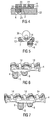
- Fig. 1 shows a perspective view of a first embodiment of a cable holder for an aircraft according to the present invention.
- Reference numeral 2 in Fig. 1 denotes a A base member having pins 6 for attachment to a structure of the aircraft.
- the pins 6 each have a corrugation 6.
- the ribbing of the Pin 6 is such as to facilitate and facilitate wetting with an adhesive.
- the pin can be coated with adhesive in such a way that the grooves of the Corrugation 8 are filled with adhesive.
- the pin 6 in corresponding d. H. corresponding dimensioned recesses introduced in the structure.
- the Ribbing at the ends of the corrugation flexible design that then when inserting the Pin 6 in a slightly smaller recess of the glue stuck in the structure of the aircraft is pressed.
- Reference numeral 4 in Fig. 1 denotes the cable holder module.
- the cable holder module 4 is detachable arranged on the base element 2.
- the base element 2 has a profile 10.
- the Cable holder module has a corresponding profile 12, wherein this profile 12 lugs has, which in each case reach over constrictions of the profile 10.
- the tabs of the profile 12 are flexible, for example by a Material rejuvenation of the material at this point, designed. This can, for example the cable holder module 4 brought to an already mounted base element 2 in cover be and by a firm pressure on the back of the cable holder module 4 firmly on the Base element 2 are pressed. This snapping the noses of the profile 12 in the Constrictions of the profile 10. By a tight train, the cable holder module 4 then be solved again by the basic element 2.
- the cable holder module 4 has a molding 14, which advantageously cable diameter or diameter of cable bundles or on outer shapes of lines to be fastened is adjusted.
- the base member 2 and the cable holder module 4 are made of plastic formed, such as polyamide.
- the basic element 2 and the cable holder module 4 can be easily and inexpensively, for example, by means of an injection molding process produce.
- the cable holder according to the present invention allows for installation on Cabin components, which are usually made of honeycomb or laminate.
- the cable holder module 4 by means of design of the profiles 10 and 12 be supported on the base element 2.
- Snap-fit connections or pins used in fits or with Barbs are used.
- the holder can be optimally integrated in the production process of the Cabin components are integrated.
- the separation of attachment of the holder on Cab component and the attachment of the cable bundle allows maximum flexibility to.
- the cable holder has up to 45% less weight according to the present invention.
- Fig. 2 shows the cable holder of Fig. 1, wherein the base member 2 and the Cable holder module 4 are separated from each other.
- Cable holder module 4 at least one locking lug 20 for engagement with a corresponding Recess in the base element 2.
- the locking lugs 20 can once with, for example barbed and next to a rotation or Protection against displacement of the cable holder module 4 on the base element 2 also for mounting of the cable holder module 4 on the base element 2 serve. In this way can be the function of the locking lugs 20 in addition to the function of the profiles 10 and 12 impact.
- the pins 20 as a simple cylindrical pins without barbs be formed and more or less only to the displacement or rotation of the basic element 2 with respect to the cable holder module 4.
- the actual holder of the cable holder module 4 on the base element 2 is then by cooperation of the Profiles 10 and 12 causes.
- the Tenon 20 or locking lugs alone be sufficient.
- a pin 6 for example at very light line routes or even a larger number such as three, four or five Pin 6 for heavier line routes or for a greater number of line routes provided.
- Fig. 3 shows another perspective view of the cable holder of Fig. 1, wherein a Top view of the cable holder module 4 is shown.
- the reference numeral 30 in Fig. 3 denotes Forming slots through which cable ties, not shown, can be pulled for fixing the cables, bundles of cables, bundles of cables or cables on the Cable holder module 4.
- FIG. 4 shows a sectional view of the cable holder of FIG. 1 along the section line A - A ', wherein the cable holder is shown mounted in a structure 32 of the aircraft.
- the pin 6 in a correspondingly dimensioned Recess 24 inserted in the structure 32 of the aircraft.
- the recess 24 may be have a slightly smaller extent than an outer diameter of the pin 6.
- the pin 6 is glued to the structure 32 of the aircraft.
- the structure 32 of the aircraft is for example a part of a cabin component or a Cabin system.
- the structure 32 may for example consist of laminate or honeycomb.
- the cable holder module 4 has pins 20, each having a have different lengths.
- the pin 20 shown on the right in Fig. 4 has a Length corresponding to approximately a thickness of the base member 2.
- the left in Fig. 4 Pin 20 of the cable holder module 4 has a length which is substantially greater than that Thickness of the base element 2.
- the left pin 20 of the cable holder module 4 is on the Cable holder module 4 arranged to be in a corresponding recess 22 in the Base element 2 is inserted, which is incorporated in the material of the pin 6.
- the base member 2 has a recess 22 for engagement with a Pin 20 of the cable holder module, wherein the recess 22 formed in the pin 6 is.
- FIG. 5 shows a sectional view of the cable holder of FIG. 3 along the section line B - B ', wherein in the cable receiving formation 14, a cable 36 or a line route 36 is provided. There are shown cables with two different diameters. Of the Section 5 of FIG. Can also be the operation of the locking lugs or the locking lug of the profile 12 of the cable holder module 4, in the constriction of the profile 10th engage or snap near the bottom of the base element 2.
- Fig. 6 shows a perspective view of a second embodiment of a Cable holder for an aircraft according to the present invention.
- the cable holder module 4 does not have a Forming 14 for receiving the cable, but two moldings 14.
- Das Basic element 2 has the same construction as the basic element 2 shown in FIG.
- Fig. 7 shows a perspective view of a third embodiment of a Cable holder according to the present invention.
- the base member 2 has the same structure as in Figs. 1 to 6 on. Only the cable holder module 4 is now to accommodate a larger number of Cables designed.
- the embodiment shown in Fig. 7 are three Forms 14 provided for receiving cable routes or cables.
Landscapes
- Engineering & Computer Science (AREA)
- Architecture (AREA)
- Civil Engineering (AREA)
- Structural Engineering (AREA)
- Aviation & Aerospace Engineering (AREA)
- Mechanical Engineering (AREA)
- Installation Of Indoor Wiring (AREA)
- Insertion, Bundling And Securing Of Wires For Electric Apparatuses (AREA)
- Connection Of Plates (AREA)
Abstract
Description
Claims (16)
- Kabelhalter für ein Flugzeug, umfassend:wobei das Grundelement Mittel (6) zur Befestigung an einer Struktur (32) des Flugzeugs aufweist;ein Grundelement (2); undein Kabelhaltermodul (4);
wobei das Kabelhaltermodul (4) zur Aufnahme von zumindest einer Leitung (36) ausgebildet ist; und
wobei das Grundelement (2) und das Kabelhaltermodul (4) lösbar miteinander verbunden sind. - Kabelhalter nach Anspruch 1,
wobei das Mittel (6) zur Befestigung zumindest einen ersten Zapfen (6) aufweist, der zum Einführen in eine erste Aussparung (26) in einer Fläche der Struktur (32) des Flugzeugs ausgebildet ist;
wobei der zumindest eine erste Zapfen (6) eine Riffelung (8) aufweist. - Kabelhalter nach einem der Ansprüche 1 oder 2,
wobei das Kabelhaltermodul (4) zumindest eine Rastnase zum Eingriff mit dem Grundelement (2) derart aufweist, dass das Kabelhaltermodul (4) auf dem Grundelement (2) gehaltert ist wenn die zumindest eine Rastnase in Eingriff mit dem Grundelement (2) ist. - Kabelhalter nach einem der Ansprüche 1 bis 3,
wobei der zumindest eine Zapfen (6) eine Riffelung (8) derart aufweist, dass eine Benetzung mit einem Klebstoff optimiert wird. - Kabelhalter nach einem der Ansprüche 1 bis 4,
wobei das Grundelement (2) und das Kabelhaltermodul (4) im Wesentlichen aus Kunststoff bestehen. - Kabelhalter nach einem der Ansprüche 1 bis 5,
wobei der Kabelhalter zur Anbringung von Leitungsbündeln auf Kabinenbauteilen (32) aus Honigwabe oder Laminat ausgebildet ist. - Kabelhalter nach einem der Ansprüche 2 bis 6,
wobei zumindest eine zweite Aussparung in dem Grundmodul (2) zum Eingriff mit zumindest einem zweiten Zapfen (20) des Kabelhaltermoduls vorgesehen ist. - Grundelementmodul für einen Kabelhalter für ein Flugzeug, umfassend:wobei das Mittel (6) zur Befestigung zumindest einen ersten Zapfen (6) aufweist, der zum Einführen in eine erste Aussparung (24) in einer Fläche der Struktur (32) des Flugzeugs ausgebildet ist; undein Grundelement (2);Mittel (6) zur Befestigung an einer Struktur des Flugzeugs;
wobei das Grundelement (2) mit einem Kabelhaltermodul (4) lösbar verbindbar ist. - Grundelementmodul nach Anspruch 8,
wobei der zumindest eine Zapfen (6) eine Riffelung (8) aufweist;
wobei das Grundelement (2) zum Eingriff mit einer Rastnase eines Kabelhaltermoduls (4) derart ausgebildet ist, dass das Kabelhaltermodul (4) auf dem Grundelement (2) gehaltert ist, wenn die Rastnase in Eingriff mit dem Grundelement ist. - Grundelementmodul nach einem der Ansprüche 8 oder 9,
wobei der zumindest eine Zapfen (6) eine Riffelung (8) derart aufweist, dass eine Benetzung mit einem Klebstoff optimiert wird; und
wobei das Grundelement im Wesentlichen aus Kunststoff besteht. - Grundelementmodul nach einem der Ansprüche 8 bis 10,
wobei das Grundelement eine zweite Aussparung (22) zum Eingriff eines zweiten Zapfens der Kabelhaltermoduls (4) aufweist. - Kabelhaltermodul für einen Kabelhalter für ein Flugzeug, umfassend:wobei das Kabelhalterelement (4) zur Aufnahme von zumindest einer Leitung (36) ausgebildet ist; undein Kabelhalterelement (4);
wobei das Kabelhalterelement (4) lösbar mit einem Grundelement (2) welches Mittel zur Anbringung an einer Struktur (32) des Flugzeugs aufweist, verbindbar ist. - Kabelhaltermodul nach Anspruch 12,
wobei das Kabelhalterelement (4) eine Rastnase zum Eingriff mit dem Grundelement (2) derart aufweist, dass das Kabelhalterelement (4) auf dem Grundelement (2) gehaltert ist wenn die Rastnase in Eingriff mit dem Grundelement (4) ist. - Kabelhaltermodul nach einem der Ansprüche 12 bis 13,
wobei das Kabelhalterelement (4) im Wesentlichen aus Kunststoff besteht; - Kabelhalterkit, umfassend:wobei das erste und das zweite Kabelhaltermodul zur Halterung von einer unterschiedlichen Anzahl von Leitungsbündeln und/oder von Leitungsbündeln mit unterschiedlichen Durchmessern ausgebildet sind.zumindest ein Grundelement (2);zumindest ein erstes Kabelhaltermodul (4); undzumindest ein zweites Kabelhaltermodul (4);
- Flugzeug mit einem Kabelhalter nach einem der Ansprüche 1 bis 7.
Applications Claiming Priority (4)
| Application Number | Priority Date | Filing Date | Title |
|---|---|---|---|
| DE102004009967A DE102004009967B4 (de) | 2004-03-01 | 2004-03-01 | Kabelhalter für ein Flugzeug, Kabelhalterkit und Flugzeug mit einem Kabelhalter |
| DE102004009967 | 2004-03-01 | ||
| US59827304P | 2004-08-03 | 2004-08-03 | |
| US598273P | 2004-08-03 |
Publications (3)
| Publication Number | Publication Date |
|---|---|
| EP1580858A2 true EP1580858A2 (de) | 2005-09-28 |
| EP1580858A3 EP1580858A3 (de) | 2006-07-26 |
| EP1580858B1 EP1580858B1 (de) | 2011-05-11 |
Family
ID=34877213
Family Applications (1)
| Application Number | Title | Priority Date | Filing Date |
|---|---|---|---|
| EP05004016A Expired - Lifetime EP1580858B1 (de) | 2004-03-01 | 2005-02-24 | Kabelhalter |
Country Status (4)
| Country | Link |
|---|---|
| US (1) | US7505665B2 (de) |
| EP (1) | EP1580858B1 (de) |
| AT (1) | ATE509409T1 (de) |
| DE (1) | DE102004009967B4 (de) |
Families Citing this family (6)
| Publication number | Priority date | Publication date | Assignee | Title |
|---|---|---|---|---|
| DE102009017977A1 (de) | 2009-04-21 | 2010-10-28 | Airbus Deutschland Gmbh | Haltevorrichtung für innerhalb eines Flugzeugrumpfs verlegte Anbauteile |
| DE102009019337B4 (de) | 2009-04-30 | 2015-05-13 | Airbus Operations Gmbh | Modulare Haltevorrichtung für innerhalb eines Flugzeugrumpfs verlegte Anbauteile |
| GB2494422A (en) * | 2011-09-07 | 2013-03-13 | Tyco Electronics Ltd Uk | Two component device for supporting and retaining wires and cables in a channel |
| DE102011120936B4 (de) | 2011-12-14 | 2017-04-06 | Diehl Comfort Modules GmbH | Modulare Kabelhalterungsvorrichtung |
| WO2014143288A1 (en) * | 2013-03-15 | 2014-09-18 | United Technologies Corporation | Modular mount assembly |
| FR3127647B1 (fr) * | 2021-09-29 | 2026-01-16 | Airbus Operations Sas | Procede et systeme de guidage a double courbure d’un collier de serrage |
Family Cites Families (26)
| Publication number | Priority date | Publication date | Assignee | Title |
|---|---|---|---|---|
| US3648560A (en) * | 1970-06-09 | 1972-03-14 | Keystone Consolidated Ind Inc | Self-extruding screw |
| DE7730437U1 (de) * | 1977-10-01 | 1978-01-12 | Fa. A. Raymond, 7850 Loerrach | Trägerplatte zur Halterung von Kabel- oder Schlauchklemmen |
| GB2027479B (en) * | 1978-05-30 | 1982-03-24 | Ford Motor Co | Holders for cables and conduits |
| DE2849257C2 (de) * | 1978-11-14 | 1981-01-22 | Sauer, Heinrich, 6501 Ober-Olm | Verbrennungskraftmaschine |
| US4618114A (en) * | 1982-09-29 | 1986-10-21 | Lof Plastics Inc. | Conduit spacer and support |
| DD251445A1 (de) * | 1986-07-22 | 1987-11-11 | Geraete & Regler Werke Veb | Adapterelement |
| DE3933305A1 (de) | 1989-10-05 | 1991-04-18 | United Carr Gmbh Trw | Halteelement aus kunststoff |
| DE4034546C2 (de) | 1990-10-30 | 1993-09-30 | United Carr Gmbh Trw | Halteelement aus Kunststoff |
| DE4213231A1 (de) * | 1990-10-30 | 1993-10-28 | United Carr Gmbh Trw | Halteelement aus Kunststoff |
| US5106040A (en) * | 1991-01-02 | 1992-04-21 | Yazaki Eds Engineering, Inc. | Steering column wire protector |
| US5316245A (en) | 1991-10-25 | 1994-05-31 | Trw United Carr Gmbh & Co., Kg | Plastic holding element |
| FR2730871B1 (fr) * | 1995-02-21 | 1997-04-11 | Rapid Sa | Dispositif de fixation d'un faisceau de cables sur une structure quelconque |
| US5601262A (en) * | 1995-03-29 | 1997-02-11 | Osram Sylvania Inc. | Cable locator |
| US5578034A (en) * | 1995-06-07 | 1996-11-26 | Danek Medical, Inc. | Apparatus for preventing screw backout in a bone plate fixation system |
| DE19607205A1 (de) * | 1996-02-26 | 1997-09-04 | United Carr Gmbh Trw | Befestigungselement auf Kunststoff |
| JP3425861B2 (ja) * | 1998-02-20 | 2003-07-14 | 富士通株式会社 | 光交換機 |
| US6249913B1 (en) * | 1998-10-09 | 2001-06-19 | General Dynamics Ots (Aerospace), Inc. | Aircraft data management system |
| DE19946890C2 (de) * | 1999-09-30 | 2003-08-14 | Raymond A & Cie | Halteelement zur unverlierbaren Halterung von Kopfschrauben |
| FR2805408B1 (fr) * | 2000-02-18 | 2005-01-21 | Plombelec | Systeme d'attache orientable et modulaire pour cables |
| DE60222815T2 (de) * | 2001-04-03 | 2008-07-03 | AUTONETWORKS Technologies, LTD., Yokkaichi | Optischer Stecker, Halterungsvorrichtung für optisches Element und Montageteil für einen optischen Stecker |
| TW563821U (en) * | 2001-09-12 | 2003-11-21 | Hon Hai Prec Ind Co Ltd | Optical switch |
| JP4068331B2 (ja) * | 2001-10-17 | 2008-03-26 | 株式会社ニフコ | クランプ |
| TW492535U (en) * | 2001-11-07 | 2002-06-21 | Hon Hai Prec Ind Co Ltd | Retaining device for optical fiber |
| WO2003084000A1 (en) * | 2002-03-27 | 2003-10-09 | Molex Incorporated | Differential signal connector assembly with improved retention capabilities |
| DE10256144A1 (de) | 2002-11-29 | 2004-06-17 | Newfrey Llc, Newark | Befestigungsvorrichtung für einen länglichen Gegenstand, insbesondere Kabelbaum |
| US7053300B2 (en) * | 2004-07-09 | 2006-05-30 | Denier Electric Company, Inc. | Multi-functional electric support bracket |
-
2004
- 2004-03-01 DE DE102004009967A patent/DE102004009967B4/de not_active Expired - Fee Related
-
2005
- 2005-02-24 EP EP05004016A patent/EP1580858B1/de not_active Expired - Lifetime
- 2005-02-24 AT AT05004016T patent/ATE509409T1/de active
- 2005-02-28 US US11/067,814 patent/US7505665B2/en not_active Expired - Fee Related
Also Published As
| Publication number | Publication date |
|---|---|
| ATE509409T1 (de) | 2011-05-15 |
| US7505665B2 (en) | 2009-03-17 |
| DE102004009967B4 (de) | 2010-03-18 |
| EP1580858B1 (de) | 2011-05-11 |
| US20050196121A1 (en) | 2005-09-08 |
| EP1580858A3 (de) | 2006-07-26 |
| DE102004009967A1 (de) | 2005-09-22 |
Similar Documents
| Publication | Publication Date | Title |
|---|---|---|
| DE19726500A1 (de) | Trennvorrichtung für eine Kabelbahn | |
| DE60025752T2 (de) | Fahrzeug-teppichanordnung mit rohrleitung | |
| EP1133039A1 (de) | Kabelhalter zur Befestigung von Kabeln in Fahrzeugen | |
| EP0555811B1 (de) | Kabelbaumartige Leitungseinheit insbesondere für Automobile | |
| DE102010039133B4 (de) | Luft- oder Raumfahrzeug mit einer Halterungsanordnung zur Halterung von Systemen | |
| EP1580858B1 (de) | Kabelhalter | |
| DE202015101776U1 (de) | Rangierwabe | |
| EP2240985B1 (de) | Installationskasten, insbesondere verteilerkasten, zur aufputzinstallation | |
| EP3281253B1 (de) | Rangierwabe | |
| DE102019121480B4 (de) | Verbindungsbrücke sowie System zur Führung von Lichtwellenleitern | |
| DE202010009722U1 (de) | Kabel- und Leitungsführung | |
| DE102017116679A1 (de) | Kabelkanal | |
| EP1674790B1 (de) | Befestigungssystem zur Montage von Leuchten in einem Lichtband | |
| DE102005046194B4 (de) | Kabelkanal mit Kanalsegmenten | |
| EP2863497B1 (de) | Verteilerschrank oder -kasten der Elektroinstallation von Gebäuden | |
| DE102011008548A1 (de) | Vorrichtung für den Anschluss von Stromkabeln | |
| DE102007018333B4 (de) | Kabelführungseinrichtung und Kabelführungsanordnung zur Verlegung von Kabeln um eine Kante | |
| DE9113317U1 (de) | Anschlußdose für elektrische Leiter von Kabeln und/oder Schnüren der Telekommunikationstechnik | |
| DE102010021919A1 (de) | Leitungssystem | |
| DE102007005059A1 (de) | Leitungsanordnung | |
| DE102025134040A1 (de) | Adapter zum befestigen einer vorrichtung auf einer tragschiene | |
| DE19757749C2 (de) | Befestigungsprofil für elektrische Geräte | |
| EP1122844B1 (de) | Kabelkanal | |
| DE102023135686A1 (de) | Verbinder für längliche Tragprofile eines Leuchtentragschienensystems | |
| DE202022103966U1 (de) | Paneelverbinder |
Legal Events
| Date | Code | Title | Description |
|---|---|---|---|
| PUAI | Public reference made under article 153(3) epc to a published international application that has entered the european phase |
Free format text: ORIGINAL CODE: 0009012 |
|
| AK | Designated contracting states |
Kind code of ref document: A2 Designated state(s): AT BE BG CH CY CZ DE DK EE ES FI FR GB GR HU IE IS IT LI LT LU MC NL PL PT RO SE SI SK TR |
|
| AX | Request for extension of the european patent |
Extension state: AL BA HR LV MK YU |
|
| PUAL | Search report despatched |
Free format text: ORIGINAL CODE: 0009013 |
|
| AK | Designated contracting states |
Kind code of ref document: A3 Designated state(s): AT BE BG CH CY CZ DE DK EE ES FI FR GB GR HU IE IS IT LI LT LU MC NL PL PT RO SE SI SK TR |
|
| AX | Request for extension of the european patent |
Extension state: AL BA HR LV MK YU |
|
| 17P | Request for examination filed |
Effective date: 20070105 |
|
| 17Q | First examination report despatched |
Effective date: 20070301 |
|
| AKX | Designation fees paid |
Designated state(s): AT BE BG CH CY CZ DE DK EE ES FI FR GB GR HU IE IS IT LI LT LU MC NL PL PT RO SE SI SK TR |
|
| GRAP | Despatch of communication of intention to grant a patent |
Free format text: ORIGINAL CODE: EPIDOSNIGR1 |
|
| GRAS | Grant fee paid |
Free format text: ORIGINAL CODE: EPIDOSNIGR3 |
|
| RAP1 | Party data changed (applicant data changed or rights of an application transferred) |
Owner name: AIRBUS OPERATIONS GMBH |
|
| GRAA | (expected) grant |
Free format text: ORIGINAL CODE: 0009210 |
|
| AK | Designated contracting states |
Kind code of ref document: B1 Designated state(s): AT BE BG CH CY CZ DE DK EE ES FI FR GB GR HU IE IS IT LI LT LU MC NL PL PT RO SE SI SK TR |
|
| REG | Reference to a national code |
Ref country code: GB Ref legal event code: FG4D Free format text: NOT ENGLISH |
|
| REG | Reference to a national code |
Ref country code: CH Ref legal event code: EP |
|
| REG | Reference to a national code |
Ref country code: IE Ref legal event code: FG4D |
|
| REG | Reference to a national code |
Ref country code: DE Ref legal event code: R096 Ref document number: 502005011354 Country of ref document: DE Effective date: 20110622 |
|
| REG | Reference to a national code |
Ref country code: NL Ref legal event code: VDEP Effective date: 20110511 |
|
| PG25 | Lapsed in a contracting state [announced via postgrant information from national office to epo] |
Ref country code: PT Free format text: LAPSE BECAUSE OF FAILURE TO SUBMIT A TRANSLATION OF THE DESCRIPTION OR TO PAY THE FEE WITHIN THE PRESCRIBED TIME-LIMIT Effective date: 20110912 Ref country code: SE Free format text: LAPSE BECAUSE OF FAILURE TO SUBMIT A TRANSLATION OF THE DESCRIPTION OR TO PAY THE FEE WITHIN THE PRESCRIBED TIME-LIMIT Effective date: 20110511 Ref country code: LT Free format text: LAPSE BECAUSE OF FAILURE TO SUBMIT A TRANSLATION OF THE DESCRIPTION OR TO PAY THE FEE WITHIN THE PRESCRIBED TIME-LIMIT Effective date: 20110511 |
|
| PG25 | Lapsed in a contracting state [announced via postgrant information from national office to epo] |
Ref country code: GR Free format text: LAPSE BECAUSE OF FAILURE TO SUBMIT A TRANSLATION OF THE DESCRIPTION OR TO PAY THE FEE WITHIN THE PRESCRIBED TIME-LIMIT Effective date: 20110812 Ref country code: CY Free format text: LAPSE BECAUSE OF FAILURE TO SUBMIT A TRANSLATION OF THE DESCRIPTION OR TO PAY THE FEE WITHIN THE PRESCRIBED TIME-LIMIT Effective date: 20110511 Ref country code: FI Free format text: LAPSE BECAUSE OF FAILURE TO SUBMIT A TRANSLATION OF THE DESCRIPTION OR TO PAY THE FEE WITHIN THE PRESCRIBED TIME-LIMIT Effective date: 20110511 Ref country code: ES Free format text: LAPSE BECAUSE OF FAILURE TO SUBMIT A TRANSLATION OF THE DESCRIPTION OR TO PAY THE FEE WITHIN THE PRESCRIBED TIME-LIMIT Effective date: 20110822 Ref country code: SI Free format text: LAPSE BECAUSE OF FAILURE TO SUBMIT A TRANSLATION OF THE DESCRIPTION OR TO PAY THE FEE WITHIN THE PRESCRIBED TIME-LIMIT Effective date: 20110511 Ref country code: IS Free format text: LAPSE BECAUSE OF FAILURE TO SUBMIT A TRANSLATION OF THE DESCRIPTION OR TO PAY THE FEE WITHIN THE PRESCRIBED TIME-LIMIT Effective date: 20110911 |
|
| REG | Reference to a national code |
Ref country code: IE Ref legal event code: FD4D |
|
| PG25 | Lapsed in a contracting state [announced via postgrant information from national office to epo] |
Ref country code: NL Free format text: LAPSE BECAUSE OF FAILURE TO SUBMIT A TRANSLATION OF THE DESCRIPTION OR TO PAY THE FEE WITHIN THE PRESCRIBED TIME-LIMIT Effective date: 20110511 |
|
| PG25 | Lapsed in a contracting state [announced via postgrant information from national office to epo] |
Ref country code: IE Free format text: LAPSE BECAUSE OF FAILURE TO SUBMIT A TRANSLATION OF THE DESCRIPTION OR TO PAY THE FEE WITHIN THE PRESCRIBED TIME-LIMIT Effective date: 20110511 Ref country code: EE Free format text: LAPSE BECAUSE OF FAILURE TO SUBMIT A TRANSLATION OF THE DESCRIPTION OR TO PAY THE FEE WITHIN THE PRESCRIBED TIME-LIMIT Effective date: 20110511 Ref country code: CZ Free format text: LAPSE BECAUSE OF FAILURE TO SUBMIT A TRANSLATION OF THE DESCRIPTION OR TO PAY THE FEE WITHIN THE PRESCRIBED TIME-LIMIT Effective date: 20110511 |
|
| PG25 | Lapsed in a contracting state [announced via postgrant information from national office to epo] |
Ref country code: DK Free format text: LAPSE BECAUSE OF FAILURE TO SUBMIT A TRANSLATION OF THE DESCRIPTION OR TO PAY THE FEE WITHIN THE PRESCRIBED TIME-LIMIT Effective date: 20110511 Ref country code: PL Free format text: LAPSE BECAUSE OF FAILURE TO SUBMIT A TRANSLATION OF THE DESCRIPTION OR TO PAY THE FEE WITHIN THE PRESCRIBED TIME-LIMIT Effective date: 20110511 Ref country code: SK Free format text: LAPSE BECAUSE OF FAILURE TO SUBMIT A TRANSLATION OF THE DESCRIPTION OR TO PAY THE FEE WITHIN THE PRESCRIBED TIME-LIMIT Effective date: 20110511 Ref country code: RO Free format text: LAPSE BECAUSE OF FAILURE TO SUBMIT A TRANSLATION OF THE DESCRIPTION OR TO PAY THE FEE WITHIN THE PRESCRIBED TIME-LIMIT Effective date: 20110511 |
|
| PLBE | No opposition filed within time limit |
Free format text: ORIGINAL CODE: 0009261 |
|
| STAA | Information on the status of an ep patent application or granted ep patent |
Free format text: STATUS: NO OPPOSITION FILED WITHIN TIME LIMIT |
|
| 26N | No opposition filed |
Effective date: 20120214 |
|
| PG25 | Lapsed in a contracting state [announced via postgrant information from national office to epo] |
Ref country code: IT Free format text: LAPSE BECAUSE OF FAILURE TO SUBMIT A TRANSLATION OF THE DESCRIPTION OR TO PAY THE FEE WITHIN THE PRESCRIBED TIME-LIMIT Effective date: 20110511 |
|
| REG | Reference to a national code |
Ref country code: DE Ref legal event code: R097 Ref document number: 502005011354 Country of ref document: DE Effective date: 20120214 |
|
| BERE | Be: lapsed |
Owner name: AIRBUS OPERATIONS G.M.B.H. Effective date: 20120228 |
|
| PG25 | Lapsed in a contracting state [announced via postgrant information from national office to epo] |
Ref country code: MC Free format text: LAPSE BECAUSE OF NON-PAYMENT OF DUE FEES Effective date: 20120229 |
|
| REG | Reference to a national code |
Ref country code: CH Ref legal event code: PL |
|
| PG25 | Lapsed in a contracting state [announced via postgrant information from national office to epo] |
Ref country code: LI Free format text: LAPSE BECAUSE OF NON-PAYMENT OF DUE FEES Effective date: 20120229 Ref country code: CH Free format text: LAPSE BECAUSE OF NON-PAYMENT OF DUE FEES Effective date: 20120229 |
|
| PG25 | Lapsed in a contracting state [announced via postgrant information from national office to epo] |
Ref country code: BE Free format text: LAPSE BECAUSE OF NON-PAYMENT OF DUE FEES Effective date: 20120228 |
|
| REG | Reference to a national code |
Ref country code: AT Ref legal event code: MM01 Ref document number: 509409 Country of ref document: AT Kind code of ref document: T Effective date: 20120224 |
|
| PG25 | Lapsed in a contracting state [announced via postgrant information from national office to epo] |
Ref country code: AT Free format text: LAPSE BECAUSE OF NON-PAYMENT OF DUE FEES Effective date: 20120224 Ref country code: BG Free format text: LAPSE BECAUSE OF FAILURE TO SUBMIT A TRANSLATION OF THE DESCRIPTION OR TO PAY THE FEE WITHIN THE PRESCRIBED TIME-LIMIT Effective date: 20110811 |
|
| PG25 | Lapsed in a contracting state [announced via postgrant information from national office to epo] |
Ref country code: TR Free format text: LAPSE BECAUSE OF FAILURE TO SUBMIT A TRANSLATION OF THE DESCRIPTION OR TO PAY THE FEE WITHIN THE PRESCRIBED TIME-LIMIT Effective date: 20110511 |
|
| PG25 | Lapsed in a contracting state [announced via postgrant information from national office to epo] |
Ref country code: LU Free format text: LAPSE BECAUSE OF NON-PAYMENT OF DUE FEES Effective date: 20120224 |
|
| PG25 | Lapsed in a contracting state [announced via postgrant information from national office to epo] |
Ref country code: HU Free format text: LAPSE BECAUSE OF FAILURE TO SUBMIT A TRANSLATION OF THE DESCRIPTION OR TO PAY THE FEE WITHIN THE PRESCRIBED TIME-LIMIT Effective date: 20050224 |
|
| REG | Reference to a national code |
Ref country code: FR Ref legal event code: PLFP Year of fee payment: 12 |
|
| REG | Reference to a national code |
Ref country code: DE Ref legal event code: R082 Ref document number: 502005011354 Country of ref document: DE Representative=s name: LKGLOBAL | LORENZ & KOPF PARTG MBB PATENTANWAE, DE Ref country code: DE Ref legal event code: R082 Ref document number: 502005011354 Country of ref document: DE Representative=s name: KOPF WESTENBERGER WACHENHAUSEN PATENTANWAELTE , DE |
|
| PGFP | Annual fee paid to national office [announced via postgrant information from national office to epo] |
Ref country code: FR Payment date: 20160218 Year of fee payment: 12 Ref country code: GB Payment date: 20160217 Year of fee payment: 12 |
|
| PGFP | Annual fee paid to national office [announced via postgrant information from national office to epo] |
Ref country code: DE Payment date: 20170217 Year of fee payment: 13 |
|
| GBPC | Gb: european patent ceased through non-payment of renewal fee |
Effective date: 20170224 |
|
| REG | Reference to a national code |
Ref country code: FR Ref legal event code: ST Effective date: 20171031 |
|
| PG25 | Lapsed in a contracting state [announced via postgrant information from national office to epo] |
Ref country code: FR Free format text: LAPSE BECAUSE OF NON-PAYMENT OF DUE FEES Effective date: 20170228 |
|
| PG25 | Lapsed in a contracting state [announced via postgrant information from national office to epo] |
Ref country code: GB Free format text: LAPSE BECAUSE OF NON-PAYMENT OF DUE FEES Effective date: 20170224 |
|
| REG | Reference to a national code |
Ref country code: DE Ref legal event code: R119 Ref document number: 502005011354 Country of ref document: DE |
|
| PG25 | Lapsed in a contracting state [announced via postgrant information from national office to epo] |
Ref country code: DE Free format text: LAPSE BECAUSE OF NON-PAYMENT OF DUE FEES Effective date: 20180901 |