EP1579046B2 - Method and apparatus for joining the edges of a tubular knitted article - Google Patents
Method and apparatus for joining the edges of a tubular knitted article Download PDFInfo
- Publication number
- EP1579046B2 EP1579046B2 EP03772671.8A EP03772671A EP1579046B2 EP 1579046 B2 EP1579046 B2 EP 1579046B2 EP 03772671 A EP03772671 A EP 03772671A EP 1579046 B2 EP1579046 B2 EP 1579046B2
- Authority
- EP
- European Patent Office
- Prior art keywords
- semi
- rank
- removal
- crown
- stitches
- Prior art date
- Legal status (The legal status is an assumption and is not a legal conclusion. Google has not performed a legal analysis and makes no representation as to the accuracy of the status listed.)
- Expired - Lifetime
Links
Images


Classifications
-
- D—TEXTILES; PAPER
- D04—BRAIDING; LACE-MAKING; KNITTING; TRIMMINGS; NON-WOVEN FABRICS
- D04B—KNITTING
- D04B9/00—Circular knitting machines with independently-movable needles
- D04B9/42—Circular knitting machines with independently-movable needles specially adapted for producing goods of particular configuration
- D04B9/46—Circular knitting machines with independently-movable needles specially adapted for producing goods of particular configuration stockings, or portions thereof
- D04B9/56—Circular knitting machines with independently-movable needles specially adapted for producing goods of particular configuration stockings, or portions thereof heel or toe portions
-
- D—TEXTILES; PAPER
- D04—BRAIDING; LACE-MAKING; KNITTING; TRIMMINGS; NON-WOVEN FABRICS
- D04B—KNITTING
- D04B15/00—Details of, or auxiliary devices incorporated in, weft knitting machines, restricted to machines of this kind
- D04B15/02—Loop-transfer points
-
- D—TEXTILES; PAPER
- D04—BRAIDING; LACE-MAKING; KNITTING; TRIMMINGS; NON-WOVEN FABRICS
- D04B—KNITTING
- D04B15/00—Details of, or auxiliary devices incorporated in, weft knitting machines, restricted to machines of this kind
- D04B15/18—Dials
-
- D—TEXTILES; PAPER
- D04—BRAIDING; LACE-MAKING; KNITTING; TRIMMINGS; NON-WOVEN FABRICS
- D04B—KNITTING
- D04B9/00—Circular knitting machines with independently-movable needles
- D04B9/02—Circular knitting machines with independently-movable needles with one set of needles
-
- D—TEXTILES; PAPER
- D04—BRAIDING; LACE-MAKING; KNITTING; TRIMMINGS; NON-WOVEN FABRICS
- D04B—KNITTING
- D04B9/00—Circular knitting machines with independently-movable needles
- D04B9/40—Circular knitting machines with independently-movable needles with provision for transfer of knitted goods from one machine to another
Definitions
- the present invention refers to an apparatus for joining the edges of a tubular knitted article, such as a stocking, upon the completion of the latter on a circular machine.
- the object of the present invention is to overcome the said drawbacks.
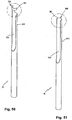
- an apparatus comprises a movable carrier 300 which is moved close to and away from a knitting head 100, and can be rotated and vertically displaced as well.
- Figs. 85 and 86 show schematically the movement of carrier 300.
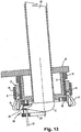
- the movable carrier 300 is supported by a relevant arm 10 horizontally disposed.
- the arm 10 is keyed on the sleeve 302 which is fitted on a relevant hollow column 301.
- a pneumatic lifting cylinder 303 Provided inside the column 301 is a pneumatic lifting cylinder 303, whose rod 308 is fixed inside the sleeve 302 in correspondence of the proximal end 307 of the arm 10.
- an extension of rod 308 corresponds to a lift of the arm 10 and of the movable carrier 300 as well supported by the latter.
- the lower portion 309 of the sleeve 302 is provided with a toothing 305.
- the toothing 305 moves to a height Q corresponding to the vertical travel of the sleeve onto the column 301 (or longer than the latter); this allows rotating the arm 10 while displacing it up to different levels.
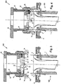
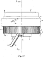
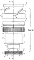
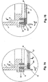
- the knitting head 100 is provided, in a known manner, with a cylinder 1, needles 2, sinkers 3, and a sinkers case 4.
- the completion of an article 6, such as a stocking, is made on the knitting head 100 with the use of a plate group 5.
- the stocking or article 6 has the configuration in which the tubular part is knitted and the toe remains open.
- the plate 5 is lifted (see Fig. 2 ) in a known manner which, therefore, will not be described herein in detail.
- the needles 2 of the knitting head 100 are lifted so as to move each stitch of article 6 to the position so-called “unloaded” in technical jargon, that is, to a level along the needle which is below the latch 201 of the needle 2 (numeral 200 indicating the needle's head).
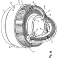
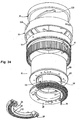
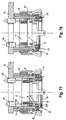
- the apparatus in question comprises the movable carrier 300 supported by the arm 10 which allows the vertical and rotational movement thereof.
- the movable carrier 300 After the plate 5 is moved away, the movable carrier 300, provided with means for the removal of the article, is superimposed to the knitting head 100. In this phase, the needles 2 are further lifted so as to move the stitches above the sinkers 3.
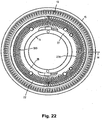
- the movable carrier 300 exhibits a support body 11 on which relevant hooks 14 are fixed and intended to move the stitches during the removal of the needles 2 from the knitting head 100.
- the supporting body 11 has a hollow cylindrical shape with two cross-sections: one upper cross-section of greater diameter 110 and one lower cross-section of smaller diameter 111.
- the hooks 14 are inserted into a corresponding number of slots 130 vertically disposed and presented by a hook-supporting crown 13 located externally and coaxially to the body 11 which supports the movable carrier 300.
- the support body 11 exhibits, in correspondence of the region connecting the upper 110 with the lower 111 section, a projecting peripheral edge or frame 112.
- a hollow cylindrical element 12 which defines a cam.
- the cam element 12 results interposed between the body 11 and the crown 13 supporting the hooks 14.
- the hooks 14 have, when viewed laterally, a substantially "L" shape, with the short leg 145 of the "L” being disposed below.
- the upper end 140 of the hooks 14 is inserted into an annular cavity 131, of rectangular cross-section, formed on the outside of crown 13.
- the hooks 14 exhibit a groove 141 on their outer side (that is, on the side facing centrifugally relative to the movable carrier 300).
- the end 140 On the inner side (that is, centripetally with respect to carrier 300), the end 140 has a triangular portion defining a step 142 connected with the apex 144 of the upper end 140 via an oblique portion 143, that is, a portion with oblique edge to the longitudinal development of the stem of hook 14.
- an elastic ring (designated by numeral 8 in Fig. 13 only, for the sake of clarity) which retains the said ends 140 inside the cavity 131 of crown 13.
- the oblique portions 143 of the hooks result in contact with and parallel to the vertical wall of cavity 131, as they are kept so retained by the elastic reaction force of the above mentioned ring.
- This determines an outwardly inclination of the stems of hooks 14, which, owing to the action of the elastic ring, result in an open configuration such as that shown also in Figs. 3 and 4 .
- the presence of the step or tooth 142 determines a restraint to the downward displacement of the hooks 14 within the slots 130 where they are inserted.
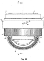
- a ring 15 (hereinafter also referred to as "hook-closing ring") intended for moving the hooks 14.
- the ring 15 is fitted on the crown 13 and is able to slide vertically relative to the same crown.
- Provided on the hook-closing ring 15 are one or more helicoidal slots 150.
- the helicoidal slots 150 act like cams able to determine the vertical movement of the hook-closing ring 15 in correspondence of the rotational movement of relevant pivots inserted into the slots 150.
- oblique slots 120 are formed on the cam element 12 to receive corresponding pivots 132 (in Fig. 28 , numeral 132 designates the axis of one of the pivots 132) which connect the cam element 12 with the crown 13 so as to allow the vertical movement of the latter upon the displacement of pivots 132 within the cams defined by the oblique slots 120.
- numeral 134 designates a hole
- numeral 135 designates the axis of the pivot inserted therein and able to connect the support body 11 with the crown 15.
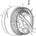
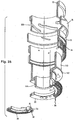
- a group of removal members 26, 25 (also called punches in the present description) to be associated, respectively, with the first and second semi-rank of the article knitted on the knitting machine 100.
- removal members 26, 25 also called punches in the present description
- only one punch or removal member 25 or 26 is shown, for the sake of clarity, when a plurality of these members is provided in repeating series, such as in Figs. 23 , 25 , 28 , 29 and others.
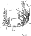
- a crown 20 fixed in the left side of the lower portion of the support body 11 is a crown 20 supporting the removal members 25 of the second semi-rank.
- the crown 20 has a half thereof provided with seats for the punches 25.
- the removal members 26 of the first semi-rank are disposed on a semicrown 21 supported by a semicircular sector 22 hinged to the lower portion 11 of body 11 in correspondence of two diametrically opposite hinges 23.
- the semicircular sector 22 can be rotated through 180° so as to dispose the semicrown 21 of the first semi-rank below the crown 20 of the second semi-rank.
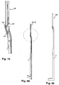
- the removal members 26 of the first semi-rank are essentially made up of a rectilinear and flat body which is tapered in its distal end 251. In correspondence of said end 251, on the side in which the taper begins, a notch 252 is formed within the thickness of the said body to receive the needle 2 of the knitting head 100 during the removal phase (as illustrated in Figs. 68-70 ). On the opposite or proximal side, the removal member 26 exhibits a stem 250 by which it is retained firmly by the support means defined by the semicrown 21.
- the removal members 25 of the second semi-rank are like those of the first semi-rank above described, as far as the free end 251 and the cavity 252 allowing the engagement thereof with the needle of the knitting machine are concerned, but they differ in the stem's region.
- numerals 25 and 26 refer generically to a removal member which is similar for both first and second semi-rank;
- Fig. 70 also shows a generic stem 250 as this part is similar for the first and second semi-rank).
- the above characteristic differentiation of the stem's region is due to the difference of the support means (that is, crown 20) which allow an oscillatory movement with radial direction, that is, with "in-out” direction with respect to the circumference of the needles.
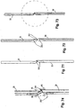
- the term "covering” refers to the partial overlapping of two elements (for example, two removal members, or one removal member and one needle) to allow the passage of a stitch from one to another of said elements without having any dead regions or times in which the stitch is not engaged by one of the two elements.
- two stitches of the article 6 are schematically represented as they are made to pass from the removal member 26 to the removal member 25, thanks to the above said covering situation.
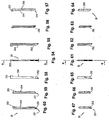
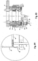
- Fig. 75-80 show how the removal member 25 is inclined either inwardly or outwardly according to the operating phase.
- Fig. 75 shows (partially) the movable carrier in removal position in which the removal member 25 is kept facing outwardly (direction indicated by the arrow V); on the contrary, in Fig. 76 the removal member is in a stitch-transfer position and is kept facing inwardly by the action of spring 19 (an elastic ring in the illustrated example) being not opposed by the semi-ring 24 which, in fact, lies in the profile 254 of the removal member; again in this figure an arrow (W) indicates the direction of displacement of the removal member 25.
- spring 19 an elastic ring in the illustrated example
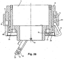
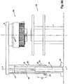
- Figs. 75-83 are shown some details that do not appear in the preceding figures, for example, pneumatic cylinders 29 provided on the arm 10.
- the pneumatic cylinders 29 operate via relevant rods 90 on a support element 17 exhibiting vertical bars 16 facing downwards.
- the support element 17 is vertically slidable inside the support body 11, and springs 18 are disposed between the latter and the support element 17 to provide a reaction able to push the element 17 upwards, that is, in a direction opposite to that of the downward thrust of rods 90.
- the springs 18 are represented only partially.
- the activation of the cylinder 29 causes the lowering of the rod 90, with the consequent downward displacement of the support element 17.
- Figs. 81-84 show an alternative embodiment of the said removal members 25.
- each removal member 25 is fixed on the relevant crown 20, and the covering condition is obtained by disposing the removal members 26 of the first semi-rank and those of the second semi-rank over two ideal circumferences of different radius and/or providing a group (for example, the punches 26) of larger size with respect to the other group of punches.
- a group for example, the punches 26
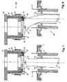
- the movable carrier 300 is placed above the knitting machine 100.
- the removal members 25 and 26 are moved closer to the respective needle heads, and the interaction between the needles 2 and removal members 25, 26 is similar to that illustrated in Figs. 68-70 .
- the hook-closing ring 15 is lowered, thereby determining the positioning of the hooks 14 below the stitches to be removed which are, therefore, in their closed configuration.
- the support crown 13 is lifted, along with the hooks 14 supported by the same crown, so that the hooks move the article's stitches upwards and the latter disengage from the needles 2 to pass onto the removal members 25 and 26. Thereafter ( Figs.
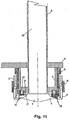
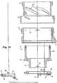
- the movable carrier 300 is further lifted and moved away form the knitting head 100 to take the article on to a hook-up station provided with an inside-out turning tube 30 in which the article 6 is inserted.
- the moving of article 6 away from the knitting head 100 can be effected soon after removing the stitches from the needles of the knitting head, as above described, or it can be effected afterwards, for example, in a possible alternative embodiment of the method, after the phase - to be described later on - in which the stitches of the two semi-ranks are moved close to each other.
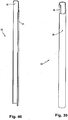
- Figs. 36-53 illustrate embodiments, to be described later on in details, of the inside-out-turning tube 30.
- the general structure of said tube can be imagined, for example, like a tubular body inside which the article is inserted when the stitches of the last semi-rank, that is, the removed stitches, are still disposed around a circumference, that is, prior to the overturning through 180° of the first semi-rank. Thereafter, by a longitudinal movement, the article engaged on the tube is forced to pass through the open end of the tube, thereby causing the inside-out turning of the article, with the stocking that will be fitted outside the tubular body.
- the inside-out-turning tube 30 is then lifted ( Figs. 9-11 ) thus causing the inside-out turning of the article which results fitted on the outside of the tube 30, with the initial end of the same article facing upwards and above the rank of stitches removed by the removal members.
- the inside-out turning tube 30 is engaged with relevant support means (not shown) in correspondence of its upper end, whereas the lower end of the tube remains free and above the plane of the removed stitches.
- inside-out turning phases above described, and those to be described below for preparing the hook-up operation can be carried out at any point of the path of the movable carrier, that is, at positions different from the one described herein by way of example.
- the hook-closing ring 15 is moved upwards thereby determining the opening of the hooks 14, that is, their displacement in centripetal direction.
- each removal member 26 of the first semi-rank lies in correspondence of a removal member 25 of the second semi-rank, with the respective free ends close to each other in a configuration similar to that described with reference to Figs. 71-74 ; in this configuration, each stitch of the first semi-rank results juxtaposed and coaxial to the corresponding stitch of the second semi-rank.
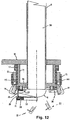
- a stitch-pushing semi-crown 28 makes the stitches slide along the removal members 26 to take them up onto the removal members 25 of the second semi-ranks located above.
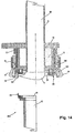
- Fig. 14 Depicted in the lower side of Fig. 14 is a portion of the hook-up machine 400, comprising a support body 42, a crown 41 with relevant hook-up spines 40, all being well known elements which, therefore, need not to be described in detail.
- the hook-up spines 40 are moved close to the removal members 25 which, as already mentioned, support the two overlapping semi-ranks of the article; afterwards, owing to the downwardly directed push of a stitch-pushing semi-crown 27 coaxial to the circumference formed by the removal members 25, the stitches are transferred onto the spines 40.
- the semi-crowns 27 and 28 are shaped alike a semicircular comb, with a series of slots 270 and 280 angularly spaced apart by such extents which correspond to the angular displacement between the removal members 26 and 25, so that the same semi-crowns are able to slide along the removal members while guided vertically by the latter.
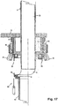
- Shown in Fig. 17 is a hook-up needle 43, by means of which the hook-up of stitches and/or pairs of stitches being fitted on spines is performed in a known manner by carrying out the necessary chain-closing knots.
- the pairs of stitches of the two semi-ranks can be supported - during the closing/hooking-up of the toe of stocking 6 - by the punches 25 of the second semi-rank, and a hook-up needle 43 can be brought close to the latter, which needle, instead of operating the hook-up on spines provided for this purpose, will perform such operation by exploiting the punches 25 which, advantageously, exhibit the said cavity 252, that is, the one used for the engagement of the needle 2.
- This operation can be carried out by using a bar 32 to be inserted into the tube 30 by an extent sufficient to complete the right-side-out arrangement of the article which, after such operation, is definitely ejected.
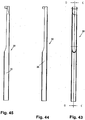
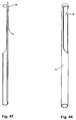
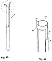
- Figs. 36-53 show exemplary embodiments of the inside-out-turning tube 30.
- One way to perform the introduction of the article into the inside-out-turning tube 30 may consist in aspirating the article inside a single tubular element.
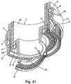
- the body of tube 30 may consist of two coaxial elements 35, 36 whose front or upper ends 350, 360, that is, those facing the article before the inside-out-turning thereof, are so shaped as to define alternately a closed or open ring by a rotation of said two elements relative to each other and about the common longitudinal axis.
- a so-formed device allows inserting the article thereinside by a transverse movement when the mouth portion is in open condition (semi-ring configuration) and definitely "trapping" the same article by a closing of its perimeter.
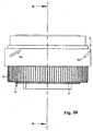
- the outer tubular element 35 has below a cylindrical closed shape; from its mid portion upwards, it exhibits a semi-cylindrical shape, that is, a wall 353 developing through about 180° on one side only with respect to the longitudinal axis, thereby defining a corresponding lateral opening or port 352 having longitudinal development; in the upper end, the element 35 exhibits a semi-ring 351 defined by a cylindrical surface of a relatively limited height and extending approximately through 180° on the side opposite to the wall 353.
- the inner tubular element 36 has in its lower part, likewise the element 35, a closed cylindrical shape; from its mid portion up to the upper end 360, it exhibits a semi-cylindrical shape, that is, a wall 363 developing through approximately 180° on one side only with respect to the longitudinal axis, thereby defining a corresponding lateral opening or port 362 having longitudinal development; the upper end 360 is thus defined by the upper edge 361 of the wall 363.
- the semi-ring 351 of the outer element 35 encircles the edge 361 of the inner element; in this way, it is possible to introduce the article 6 inside the tube by a simple translation movement without the need of moving the tube vertically downwards by a stroke which would be substantially equal to the length of the knitted article. This brings about a significant reduction of the apparatus overall dimensions. Thereafter, by a simple relative rotation of the two elements 35 and 36 the tube 30 is closed, thereby allowing the inside-out-turning operation.
- the structure of the said tube can be imagined, for example, like a tubular body inside which the article is inserted when the stitches of the last semi-rank, that is, the removed stitches, are still disposed around a circumference, that is, prior to the overturning through 180° of the first semi-rank. Thereafter, by a longitudinal movement, the article engaged on the tube is forced to pass through the open end of the tube and is thus turned inside-out. It will be appreciated that, at this point, the stocking is fitted outside the tubular body. The said tubular body, after the said movement, remains engaged with a support located on the side opposite to the article.
- the now closed toe of the article will result in proximity of the tube's mouth, so that, by inserting a core of suitable size into the tube's mouth, the same core will be in contact with the article's fabric and, by keeping to move downwards will drive the same article along with it and the latter, by sliding over the edge of the tube will move thereinside by taking up the right-side out configuration which it had originally.
- Such operation can be carried out and/or assisted by a pneumatic or suction flow.
Landscapes
- Engineering & Computer Science (AREA)
- Textile Engineering (AREA)
- Knitting Machines (AREA)
- Treatment Of Fiber Materials (AREA)
- Sewing Machines And Sewing (AREA)
- Replacement Of Web Rolls (AREA)
Priority Applications (1)
| Application Number | Priority Date | Filing Date | Title |
|---|---|---|---|
| SI200331392T SI1579046T1 (sl) | 2002-10-21 | 2003-10-17 | Postopek in naprava za zdruĹľevanje robov cevastopletenega artikla |
Applications Claiming Priority (3)
| Application Number | Priority Date | Filing Date | Title |
|---|---|---|---|
| ITFI20020199 | 2002-10-21 | ||
| IT000199A ITFI20020199A1 (it) | 2002-10-21 | 2002-10-21 | Metodo e apparato per unire i lembi di un manufatto tubolare tessuto a maglia |
| PCT/IT2003/000638 WO2004035894A1 (en) | 2002-10-21 | 2003-10-17 | Method and apparatus for joining the edges of a tubular knitted article |
Publications (3)
| Publication Number | Publication Date |
|---|---|
| EP1579046A1 EP1579046A1 (en) | 2005-09-28 |
| EP1579046B1 EP1579046B1 (en) | 2008-07-16 |
| EP1579046B2 true EP1579046B2 (en) | 2018-02-14 |
Family
ID=32104760
Family Applications (1)
| Application Number | Title | Priority Date | Filing Date |
|---|---|---|---|
| EP03772671.8A Expired - Lifetime EP1579046B2 (en) | 2002-10-21 | 2003-10-17 | Method and apparatus for joining the edges of a tubular knitted article |
Country Status (18)
| Country | Link |
|---|---|
| US (1) | US7107797B2 (enExample) |
| EP (1) | EP1579046B2 (enExample) |
| JP (1) | JP4268136B2 (enExample) |
| KR (1) | KR101068371B1 (enExample) |
| CN (1) | CN1723308B (enExample) |
| AT (1) | ATE401442T1 (enExample) |
| AU (1) | AU2003279562A1 (enExample) |
| BR (1) | BR0315448A (enExample) |
| DE (1) | DE60322262D1 (enExample) |
| DK (1) | DK1579046T3 (enExample) |
| ES (1) | ES2310675T3 (enExample) |
| IT (1) | ITFI20020199A1 (enExample) |
| MX (1) | MXPA05004221A (enExample) |
| PT (1) | PT1579046E (enExample) |
| RU (1) | RU2300584C2 (enExample) |
| SI (1) | SI1579046T1 (enExample) |
| TW (1) | TWI292786B (enExample) |
| WO (1) | WO2004035894A1 (enExample) |
Families Citing this family (63)
| Publication number | Priority date | Publication date | Assignee | Title |
|---|---|---|---|---|
| ITMI20042084A1 (it) * | 2004-11-02 | 2005-02-02 | Cesare Colosio S P A | Dispositivo di cucitura automatica particolarmente per macchine per calze |
| ITFI20060080A1 (it) * | 2006-03-28 | 2007-09-29 | Conti P | Dispositivo per chiudere la punta di un calzino |
| WO2007135697A1 (en) | 2006-05-22 | 2007-11-29 | Orion Srl | Integrated system and relative device for closing the stocking on circular machines for the production of semi-finished tubular knitting |
| ITMI20061720A1 (it) * | 2006-09-08 | 2008-03-09 | Sangiacomo Spa | Dispositivo rovesciatore di manufatti tubolari,particolarmente per macchine circolari per maglieria dotate di una stazione di chiusura di un'estremita' assiale del manufatto tubolare. |
| ITMI20061717A1 (it) * | 2006-09-08 | 2008-03-09 | Sangiacomo Spa | Dispositivo rovesciatore di manufatti tubolari,particolarmente per macchine circolari per maglieria dotate di una stazione di chiusura di un'estremita assiale del manufatto tubolare |
| ITMI20080397A1 (it) | 2008-03-10 | 2009-09-11 | Lonati Spa | Procedimento ed apparecchiatura per eseguire la chiusura di un manufatto tubolare a maglia in corrispondenza di una sua estremita' assiale, al termine del suo ciclo di produzione su una macchina circolare per maglieria, calzetteria o simile. |
| ITMI20080399A1 (it) * | 2008-03-10 | 2009-09-11 | Lonati Spa | Dispositivo rovesciatore di manufatti tubolari a maglia, particolarmente per stazioni di cucitura o di rimagliatura per la chiusura automatizzata dei manufatti tubolari in corrispondenza di una loro estremita' assiale. |
| ITMI20080398A1 (it) * | 2008-03-10 | 2009-09-11 | Lonati Spa | Dispositivo prelevatore per operare il prelievo di un manufatto tubolare a maglia da una macchina circolare per maglieria, calzetteria o simile e il suo trasferimento ad un'unita' atta ad eseguire ulteriori operazioni sul manufatto. |
| IT1392646B1 (it) * | 2009-01-30 | 2012-03-16 | N T A S R L | Dispositivo di prelievo di una calza da un macchinario cilindrico per la produzione di manufatti tubolari con estremita cucita |
| CN101929028B (zh) * | 2009-06-19 | 2014-10-29 | 马西莫·比安基 | 用于封闭管状针织袜制品末端处的袜头的装置和方法 |
| CN102644155A (zh) * | 2012-04-06 | 2012-08-22 | 东阳市创亿针织机械有限公司 | 织袜机防扭曲装置 |
| US8443633B1 (en) * | 2012-09-05 | 2013-05-21 | Da Kong Enterprise Co., Ltd. | Apparatus and method for transferring loops from the knitting machine needle |
| CN102885408B (zh) * | 2012-09-30 | 2015-03-25 | 浙江罗速设备制造有限公司 | 织袜、缝头一体式袜机 |
| ITMI20130050A1 (it) * | 2013-01-16 | 2014-07-17 | Lonati Spa | Procedimento per attuare la chiusura automatizzata di un'estremita' assiale di un manufatto tubolare e il suo scarico in assetto a rovescio ed apparecchiatura per la sua esecuzione. |
| ITFI20130081A1 (it) | 2013-04-12 | 2014-10-13 | Gianni Conti | "metodo e macchina per la tessitura di manufatti tubolari a maglia" |
| TWI539050B (zh) * | 2013-11-15 | 2016-06-21 | Da Kong Entpr Co Ltd | Sewing sock machine needle plate |
| TWI509121B (zh) * | 2013-11-15 | 2015-11-21 | Da Kong Entpr Co Ltd | Socks sewing device |
| TW201536975A (zh) * | 2014-03-25 | 2015-10-01 | Da Kong Entpr Co Ltd | 翻襪裝置及翻襪方法 |
| JP5854364B1 (ja) * | 2014-08-29 | 2016-02-09 | 永田精機株式会社 | 丸編機の編地縫合方法及び丸編機システム |
| EP3187633B1 (en) * | 2014-08-29 | 2019-03-06 | Nagata Seiki Co., Ltd. | Circular knitting machine knitted fabric seaming method and circular knitting machine system |
| JP5813192B1 (ja) * | 2014-08-29 | 2015-11-17 | 永田精機株式会社 | 丸編機の編地移し方法及び装置 |
| TWI683045B (zh) * | 2014-10-01 | 2020-01-21 | 義大利商史陶伯利義大利公司 | 用於編織管狀編織物件的方法及機器 |
| SI3204544T1 (sl) * | 2014-10-10 | 2019-05-31 | Staubli Italia S.P.A. | Postopek in naprava za pletenje cevastih pletenih izdelkov |
| TWI589747B (zh) * | 2015-03-04 | 2017-07-01 | Coil folding device | |
| DE102015103639B4 (de) * | 2015-03-12 | 2020-04-23 | Terrot Gmbh | Nadelzylinder und Rundstrickmaschine |
| CN104818571B (zh) * | 2015-04-24 | 2017-02-01 | 绍兴市越发机械制造有限公司 | 一种全成形袜子生产装置及生产工艺 |
| CN104818575A (zh) * | 2015-04-24 | 2015-08-05 | 绍兴市越发机械制造有限公司 | 一种成形袜机袜子转移装置 |
| KR102596015B1 (ko) | 2015-10-21 | 2023-10-30 | 스타우블리 이탈리아 에스.피.에이. | 원형 편물기로부터 관형상 편성 물품을 픽업하는 장치 및 방법 |
| CN105887312B (zh) * | 2015-12-07 | 2018-08-07 | 浙江海润精工机械有限公司 | 转移缝头 |
| CN105887323B (zh) * | 2015-12-07 | 2018-08-07 | 浙江海润精工机械有限公司 | 转移缝合装置 |
| CN105887317B (zh) * | 2015-12-07 | 2018-05-04 | 浙江海润精工机械有限公司 | 一种织袜缝合方法 |
| CN105887318B (zh) * | 2015-12-07 | 2018-11-16 | 浙江海润精工机械有限公司 | 一种具有翻袜功能的一体式袜机 |
| CN105887310B (zh) * | 2015-12-07 | 2018-04-24 | 浙江海润精工机械有限公司 | 一种织袜缝合及翻袜方法 |
| CN105887316B (zh) * | 2015-12-07 | 2018-11-16 | 浙江海润精工机械有限公司 | 从袜机的针筒转移袜子的转移方法 |
| CN105887313B (zh) * | 2015-12-07 | 2018-04-24 | 浙江海润精工机械有限公司 | 一种织袜缝合方法 |
| CN105887325B (zh) * | 2015-12-07 | 2018-05-18 | 浙江海润精工机械有限公司 | 一种织袜缝合方法 |
| CN105887319B (zh) * | 2015-12-07 | 2018-10-16 | 浙江海润精工机械有限公司 | 转移缝合装置 |
| CN105887322B (zh) * | 2015-12-07 | 2018-05-18 | 浙江海润精工机械有限公司 | 转移缝头 |
| CN105887321B (zh) * | 2015-12-07 | 2018-04-24 | 浙江海润精工机械有限公司 | 转移缝合装置 |
| CN105887315B (zh) * | 2015-12-07 | 2018-03-02 | 浙江海润精工机械有限公司 | 一种织袜缝合方法 |
| CN105887324B (zh) * | 2015-12-07 | 2018-05-18 | 浙江海润精工机械有限公司 | 转移缝头 |
| CN105887320B (zh) * | 2015-12-07 | 2018-01-16 | 浙江海润精工机械有限公司 | 一体式袜机 |
| ITUA20162241A1 (it) | 2016-04-01 | 2017-10-01 | Staeubli Italia S P A | Dispositivo di rimagliatura e macchina comprendente detto dispositivo |
| CN106120130B (zh) * | 2016-06-29 | 2019-03-12 | 浙江海润精工机械有限公司 | 一种转移袜针上的袜线的方法 |
| IT201600072994A1 (it) * | 2016-07-13 | 2018-01-13 | Lonati Spa | Dispositivo prelevatore per operare il prelievo di un manufatto tubolare a maglia da una macchina circolare per maglieria, calzetteria o simile e il suo trasferimento ad un’unita’ atta ad eseguire ulteriori operazioni sul manufatto. |
| CN106037119A (zh) * | 2016-07-25 | 2016-10-26 | 信泰(福建)科技有限公司 | 一体鞋面制造方法及一体编织鞋面 |
| WO2019197928A1 (en) * | 2018-04-11 | 2019-10-17 | Santoni S.P.A. | Turning device for tubular knitted items and method for turning tubular knitted items |
| TWI726304B (zh) * | 2018-08-20 | 2021-05-01 | 大康織機股份有限公司 | 從針織機的織針轉移線圈以及縫紉之機制 |
| TWI748170B (zh) * | 2018-08-20 | 2021-12-01 | 大康織機股份有限公司 | 管狀織物之翻面機構及其方法 |
| CN110230145B (zh) * | 2018-11-02 | 2024-07-05 | 浙江叶晓针织机械有限公司 | 一种袜机 |
| PT3715511T (pt) * | 2019-03-26 | 2022-12-07 | Staeubli Italia S P A | Método e dispositivo para inverter um artigo tubular tricotado numa máquina de tricotar circular |
| IT201900005636A1 (it) | 2019-04-11 | 2020-10-11 | Gianni Conti | Metodo ed apparecchiatura per la produzione di manufatti tubolari a maglia a punta chiusa |
| IT201900005838A1 (it) | 2019-04-16 | 2020-10-16 | Lonati Spa | Dispositivo prelevatore per operare il prelievo di un manufatto tubolare a maglia da una macchina circolare per maglieria, calzetteria o simile e il suo trasferimento ad un'unità atta ad eseguire ulteriori operazioni sul manufatto. |
| TWD207731S (zh) * | 2019-06-12 | 2020-10-11 | 義大利商聖東尼股份公司 | 紡織機組件 |
| IT201900023433A1 (it) * | 2019-12-10 | 2021-06-10 | Lonati Spa | Dispositivo prelevatore per operare il prelievo di un manufatto tubolare a maglia da una macchina circolare per maglieria, calzetteria o simile |
| IT201900023577A1 (it) * | 2019-12-11 | 2021-06-11 | Lonati Spa | Dispositivo prelevatore per operare il prelievo di un manufatto tubolare a maglia da una macchina circolare per maglieria, calzetteria o simile. |
| IT201900024108A1 (it) * | 2019-12-16 | 2021-06-16 | Sgm Automazioni S R L | Procedimento per chiudere un’estremità di un manufatto tubolare direttamente su macchine circolari per calzetteria e maglieria e relativa macchina circolare |
| HRP20250281T1 (hr) * | 2020-03-24 | 2025-04-25 | Lonati S.P.A. | Stroj za kružno pletenje za proizvodnju cjevastih proizvoda |
| CN111304821B (zh) * | 2020-04-09 | 2021-06-29 | 大康织机股份有限公司 | 导袜针组 |
| CN111621912B (zh) * | 2020-05-27 | 2022-03-25 | 华尔科技集团股份有限公司 | 一种针织鞋面编织方法 |
| CN111809300A (zh) * | 2020-07-13 | 2020-10-23 | 浙江凯强轻纺机械有限公司 | 移袜抓取装置 |
| MX2023000493A (es) * | 2020-10-01 | 2023-02-13 | Lonati Spa | Procedimiento para cerrar un producto tubular tricotado en un extremo axial del mismo. |
| CN113943999B (zh) * | 2021-10-15 | 2023-03-14 | 浙江嘉志利智能科技有限公司 | 用于缝合管状织物的方法 |
Citations (7)
| Publication number | Priority date | Publication date | Assignee | Title |
|---|---|---|---|---|
| US1068853A (en) † | 1912-07-06 | 1913-07-29 | Louis N D Williams | Stitch-transferring device. |
| US1188125A (en) † | 1915-08-06 | 1916-06-20 | Louis N D Williams | Stitch transferring and uniting device. |
| US1192328A (en) † | 1912-05-31 | 1916-07-25 | John Lawson | Circular-knitting machine. |
| EP0592376A1 (fr) † | 1992-10-09 | 1994-04-13 | FABRIC & MANUFACTURING PRINCIPLES, INC. | Procédé et dispositif pour réaliser l'union de deux bords d'un produit manufacturé tubulaire tricoté au terme de sa formation |
| US5487281A (en) † | 1993-07-12 | 1996-01-30 | Fabritex S.R.L. | Method and apparatus for joining two edges of a knitted tubular article |
| US5551260A (en) † | 1993-07-29 | 1996-09-03 | Fabritex, S.R.L. | Method for joining two edges of a knitted tubular article upon completion thereof |
| IT1277396B1 (it) † | 1995-07-28 | 1997-11-10 | Matec Srl | Procedimento e dispositivo per eseguire l'unione di due lembi di un manufatto tubolare al termine della sua formazione particolarmente |
Family Cites Families (9)
| Publication number | Priority date | Publication date | Assignee | Title |
|---|---|---|---|---|
| IT1269117B (it) * | 1994-06-16 | 1997-03-21 | Golden Lady Spa | Dispositivo per la automatica formazione iniziale di una punta chiusa in un manufatto tubolare a maglia su macchine da maglieria circolari |
| IT1277395B1 (it) * | 1995-07-28 | 1997-11-10 | Matec Srl | Procedimento per la produzione di calze o simili a punta chiusa con una macchina circolare monocilindrica |
| IT1281598B1 (it) * | 1996-01-08 | 1998-02-20 | Matec Srl | Macchina circolare monocilindrica per maglieria calzetteria o simile ad elevata versatilita' di impiego |
| IT1297377B1 (it) * | 1997-12-04 | 1999-09-01 | Fabritex Srl | Metodo e dispositivo per la fabbricazione di manufatti tessili tubolari |
| ITFI980039A1 (it) * | 1998-02-20 | 1999-08-20 | Fabritex Srl | Metodo ed apparecchiatura per unire i lembi di manufatti tessuti a maglia. |
| RU2168574C2 (ru) * | 1998-02-20 | 2001-06-10 | Фабритекс С.р.л. | Способ сшивания краев трубчатого вязаного изделия, устройство для сшивания краев трубчатого вязаного изделия |
| IT1304868B1 (it) * | 1998-07-07 | 2001-04-05 | Golden Lady Spa | Metodo e dispositivo per la chiusura della punta di un manufattotubolare su una macchina da maglieria |
| ITCO990009A1 (it) * | 1999-03-03 | 2000-09-03 | Franco Sciacca | Metodo ed apparecchiatura per la produzione di articoli tubolari di maglieria forniti di una o piu' aperture e o bretelle complete e prodott |
| ITFI20010038A1 (it) * | 2001-03-08 | 2002-09-08 | Metalworking And Finance Group | Dispositivo per il prelievo di un manufatto tubolare a maglia da una macchina da maglieria e per la cucitura della punta |
-
2002
- 2002-10-21 IT IT000199A patent/ITFI20020199A1/it unknown
-
2003
- 2003-10-17 MX MXPA05004221A patent/MXPA05004221A/es active IP Right Grant
- 2003-10-17 BR BR0315448-3A patent/BR0315448A/pt not_active IP Right Cessation
- 2003-10-17 DE DE60322262T patent/DE60322262D1/de not_active Expired - Fee Related
- 2003-10-17 RU RU2005115254/12A patent/RU2300584C2/ru not_active IP Right Cessation
- 2003-10-17 AT AT03772671T patent/ATE401442T1/de not_active IP Right Cessation
- 2003-10-17 SI SI200331392T patent/SI1579046T1/sl unknown
- 2003-10-17 ES ES03772671T patent/ES2310675T3/es not_active Expired - Lifetime
- 2003-10-17 DK DK03772671T patent/DK1579046T3/da active
- 2003-10-17 AU AU2003279562A patent/AU2003279562A1/en not_active Abandoned
- 2003-10-17 CN CN2003801037770A patent/CN1723308B/zh not_active Expired - Lifetime
- 2003-10-17 WO PCT/IT2003/000638 patent/WO2004035894A1/en not_active Ceased
- 2003-10-17 US US10/532,063 patent/US7107797B2/en not_active Expired - Lifetime
- 2003-10-17 PT PT03772671T patent/PT1579046E/pt unknown
- 2003-10-17 KR KR1020057006909A patent/KR101068371B1/ko not_active Expired - Fee Related
- 2003-10-17 EP EP03772671.8A patent/EP1579046B2/en not_active Expired - Lifetime
- 2003-10-17 JP JP2004544695A patent/JP4268136B2/ja not_active Expired - Lifetime
-
2004
- 2004-01-29 TW TW093101950A patent/TWI292786B/zh not_active IP Right Cessation
Patent Citations (7)
| Publication number | Priority date | Publication date | Assignee | Title |
|---|---|---|---|---|
| US1192328A (en) † | 1912-05-31 | 1916-07-25 | John Lawson | Circular-knitting machine. |
| US1068853A (en) † | 1912-07-06 | 1913-07-29 | Louis N D Williams | Stitch-transferring device. |
| US1188125A (en) † | 1915-08-06 | 1916-06-20 | Louis N D Williams | Stitch transferring and uniting device. |
| EP0592376A1 (fr) † | 1992-10-09 | 1994-04-13 | FABRIC & MANUFACTURING PRINCIPLES, INC. | Procédé et dispositif pour réaliser l'union de deux bords d'un produit manufacturé tubulaire tricoté au terme de sa formation |
| US5487281A (en) † | 1993-07-12 | 1996-01-30 | Fabritex S.R.L. | Method and apparatus for joining two edges of a knitted tubular article |
| US5551260A (en) † | 1993-07-29 | 1996-09-03 | Fabritex, S.R.L. | Method for joining two edges of a knitted tubular article upon completion thereof |
| IT1277396B1 (it) † | 1995-07-28 | 1997-11-10 | Matec Srl | Procedimento e dispositivo per eseguire l'unione di due lembi di un manufatto tubolare al termine della sua formazione particolarmente |
Also Published As
| Publication number | Publication date |
|---|---|
| EP1579046B1 (en) | 2008-07-16 |
| US7107797B2 (en) | 2006-09-19 |
| MXPA05004221A (es) | 2005-09-20 |
| TWI292786B (en) | 2008-01-21 |
| ATE401442T1 (de) | 2008-08-15 |
| JP4268136B2 (ja) | 2009-05-27 |
| DK1579046T3 (da) | 2008-11-17 |
| TW200525061A (en) | 2005-08-01 |
| AU2003279562A8 (en) | 2004-05-04 |
| CN1723308B (zh) | 2010-08-18 |
| HK1086310A1 (en) | 2006-09-15 |
| SI1579046T1 (sl) | 2008-12-31 |
| RU2005115254A (ru) | 2006-01-27 |
| KR101068371B9 (ko) | 2023-05-16 |
| KR20050083795A (ko) | 2005-08-26 |
| DE60322262D1 (de) | 2008-08-28 |
| ES2310675T3 (es) | 2009-01-16 |
| AU2003279562A1 (en) | 2004-05-04 |
| KR101068371B1 (ko) | 2011-09-28 |
| WO2004035894A1 (en) | 2004-04-29 |
| CN1723308A (zh) | 2006-01-18 |
| JP2006503991A (ja) | 2006-02-02 |
| RU2300584C2 (ru) | 2007-06-10 |
| BR0315448A (pt) | 2005-08-16 |
| EP1579046A1 (en) | 2005-09-28 |
| US20060144095A1 (en) | 2006-07-06 |
| PT1579046E (pt) | 2008-10-07 |
| ITFI20020199A1 (it) | 2004-04-22 |
Similar Documents
| Publication | Publication Date | Title |
|---|---|---|
| EP1579046B2 (en) | Method and apparatus for joining the edges of a tubular knitted article | |
| EP0942086B1 (en) | Method and apparatus for seaming edges of knitted articles | |
| CN101970737B (zh) | 在用于袜类等的圆型针织机上管状针织物件的生产循环结束时用于在其轴向端封闭管状针织物件的方法和装置 | |
| KR940009400A (ko) | 마무리 됐을때 짜여진 관상의 물품의 두변부를 꿰매어 맞추는 장치와 방법 | |
| CN108291340B (zh) | 用于从圆形针织机拾取管状针织物品的装置和方法 | |
| JP2006503991A5 (enExample) | ||
| CN101970740A (zh) | 尤其是用于在管状物件的轴向端自动封闭管状物件的缝织或钩织工位的用于管状针织物件的翻转装置 | |
| RU2130094C1 (ru) | Способ заделывания исходного конца трикотажного изделия, такого как носок и тому подобного изделия, и устройство для его осуществления | |
| US5551260A (en) | Method for joining two edges of a knitted tubular article upon completion thereof | |
| EP1417365B9 (en) | Method and apparatus for moving the stitches of a knitted tubular article to an operating station | |
| CN114008258B (zh) | 翻转装置、含其的圆形针织机及翻转管状针织物品的方法 | |
| RU96103624A (ru) | Устройство и способ заделывания исходного конца трикотажного изделия, такого, как носок или т.п. | |
| WO2008028575A1 (en) | Device for reversing tubular articles, particularly for circular knitting machines provided with a station for closing an axial end of the tubular article | |
| EP0803599B1 (en) | Single-cylinder circular hosiery-making or knitting machine particularly for manufacturing tubular items closed at one of their axial ends | |
| HK1086310B (en) | Method and apparatus for joining the edges of a tubular knitted article | |
| EP0962567A2 (en) | Circular knitting machine with flip-over half-dial | |
| CZ20023028A3 (en) | Device for closing toes in knitting machine |
Legal Events
| Date | Code | Title | Description |
|---|---|---|---|
| PUAI | Public reference made under article 153(3) epc to a published international application that has entered the european phase |
Free format text: ORIGINAL CODE: 0009012 |
|
| 17P | Request for examination filed |
Effective date: 20050422 |
|
| AK | Designated contracting states |
Kind code of ref document: A1 Designated state(s): AT BE BG CH CY CZ DE DK EE ES FI FR GB GR HU IE IT LI LU MC NL PT RO SE SI SK TR |
|
| AX | Request for extension of the european patent |
Extension state: AL LT LV MK |
|
| DAX | Request for extension of the european patent (deleted) | ||
| RIN1 | Information on inventor provided before grant (corrected) |
Inventor name: FRULLINI, PAOLO Inventor name: FRULLINI, ALBERTO |
|
| GRAP | Despatch of communication of intention to grant a patent |
Free format text: ORIGINAL CODE: EPIDOSNIGR1 |
|
| GRAS | Grant fee paid |
Free format text: ORIGINAL CODE: EPIDOSNIGR3 |
|
| GRAA | (expected) grant |
Free format text: ORIGINAL CODE: 0009210 |
|
| RAP1 | Party data changed (applicant data changed or rights of an application transferred) |
Owner name: FABRITEX S.R.L Owner name: SANTONI S.P.A. |
|
| AK | Designated contracting states |
Kind code of ref document: B1 Designated state(s): AT BE BG CH CY CZ DE DK EE ES FI FR GB GR HU IE IT LI LU MC NL PT RO SE SI SK TR |
|
| REG | Reference to a national code |
Ref country code: GB Ref legal event code: FG4D |
|
| REG | Reference to a national code |
Ref country code: CH Ref legal event code: EP |
|
| REF | Corresponds to: |
Ref document number: 60322262 Country of ref document: DE Date of ref document: 20080828 Kind code of ref document: P |
|
| REG | Reference to a national code |
Ref country code: IE Ref legal event code: FG4D |
|
| REG | Reference to a national code |
Ref country code: PT Ref legal event code: SC4A Free format text: AVAILABILITY OF NATIONAL TRANSLATION Effective date: 20080924 |
|
| REG | Reference to a national code |
Ref country code: SE Ref legal event code: TRGR |
|
| REG | Reference to a national code |
Ref country code: RO Ref legal event code: EPE |
|
| REG | Reference to a national code |
Ref country code: CH Ref legal event code: NV Representative=s name: BRAUNPAT BRAUN EDER AG |
|
| REG | Reference to a national code |
Ref country code: GR Ref legal event code: EP Ref document number: 20080402773 Country of ref document: GR |
|
| REG | Reference to a national code |
Ref country code: DK Ref legal event code: T3 |
|
| PGFP | Annual fee paid to national office [announced via postgrant information from national office to epo] |
Ref country code: NL Payment date: 20081031 Year of fee payment: 6 |
|
| REG | Reference to a national code |
Ref country code: EE Ref legal event code: FG4A Ref document number: E002555 Country of ref document: EE Effective date: 20081014 |
|
| REG | Reference to a national code |
Ref country code: ES Ref legal event code: FG2A Ref document number: 2310675 Country of ref document: ES Kind code of ref document: T3 |
|
| PGFP | Annual fee paid to national office [announced via postgrant information from national office to epo] |
Ref country code: CH Payment date: 20081015 Year of fee payment: 6 Ref country code: DE Payment date: 20081021 Year of fee payment: 6 Ref country code: DK Payment date: 20081027 Year of fee payment: 6 Ref country code: EE Payment date: 20081020 Year of fee payment: 6 Ref country code: IE Payment date: 20081020 Year of fee payment: 6 Ref country code: LU Payment date: 20081030 Year of fee payment: 6 Ref country code: MC Payment date: 20081020 Year of fee payment: 6 |
|
| PGFP | Annual fee paid to national office [announced via postgrant information from national office to epo] |
Ref country code: AT Payment date: 20081030 Year of fee payment: 6 Ref country code: ES Payment date: 20081020 Year of fee payment: 6 Ref country code: FI Payment date: 20081020 Year of fee payment: 6 Ref country code: PT Payment date: 20081017 Year of fee payment: 6 Ref country code: RO Payment date: 20081015 Year of fee payment: 6 Ref country code: SK Payment date: 20080910 Year of fee payment: 6 |
|
| PGFP | Annual fee paid to national office [announced via postgrant information from national office to epo] |
Ref country code: BG Payment date: 20081021 Year of fee payment: 6 Ref country code: SE Payment date: 20081027 Year of fee payment: 6 Ref country code: CY Payment date: 20081020 Year of fee payment: 6 Ref country code: BE Payment date: 20081105 Year of fee payment: 6 |
|
| PLBI | Opposition filed |
Free format text: ORIGINAL CODE: 0009260 |
|
| PGFP | Annual fee paid to national office [announced via postgrant information from national office to epo] |
Ref country code: FR Payment date: 20081029 Year of fee payment: 6 |
|
| 26 | Opposition filed |
Opponent name: MANNUCCI, MICHELE Effective date: 20090401 |
|
| PLAX | Notice of opposition and request to file observation + time limit sent |
Free format text: ORIGINAL CODE: EPIDOSNOBS2 |
|
| PGFP | Annual fee paid to national office [announced via postgrant information from national office to epo] |
Ref country code: GB Payment date: 20081020 Year of fee payment: 6 Ref country code: GR Payment date: 20081022 Year of fee payment: 6 Ref country code: SI Payment date: 20081017 Year of fee payment: 6 |
|
| NLR1 | Nl: opposition has been filed with the epo |
Opponent name: MANNUCCI, MICHELE |
|
| PLAF | Information modified related to communication of a notice of opposition and request to file observations + time limit |
Free format text: ORIGINAL CODE: EPIDOSCOBS2 |
|
| PLAF | Information modified related to communication of a notice of opposition and request to file observations + time limit |
Free format text: ORIGINAL CODE: EPIDOSCOBS2 |
|
| PLBB | Reply of patent proprietor to notice(s) of opposition received |
Free format text: ORIGINAL CODE: EPIDOSNOBS3 |
|
| PGFP | Annual fee paid to national office [announced via postgrant information from national office to epo] |
Ref country code: HU Payment date: 20081111 Year of fee payment: 6 |
|
| REG | Reference to a national code |
Ref country code: HU Ref legal event code: AG4A Ref document number: E006660 Country of ref document: HU |
|
| REG | Reference to a national code |
Ref country code: PT Ref legal event code: MM4A Free format text: LAPSE DUE TO NON-PAYMENT OF FEES Effective date: 20100419 |
|
| BERE | Be: lapsed |
Owner name: SANTONI S.P.A. Effective date: 20091031 Owner name: FABRITEX S.R.L Effective date: 20091031 |
|
| PG25 | Lapsed in a contracting state [announced via postgrant information from national office to epo] |
Ref country code: MC Free format text: LAPSE BECAUSE OF NON-PAYMENT OF DUE FEES Effective date: 20091031 |
|
| REG | Reference to a national code |
Ref country code: CH Ref legal event code: PL |
|
| EUG | Se: european patent has lapsed | ||
| REG | Reference to a national code |
Ref country code: DK Ref legal event code: EBP |
|
| REG | Reference to a national code |
Ref country code: EE Ref legal event code: MM4A Ref document number: E002555 Country of ref document: EE Effective date: 20091031 |
|
| REG | Reference to a national code |
Ref country code: NL Ref legal event code: V1 Effective date: 20100501 |
|
| REG | Reference to a national code |
Ref country code: SK Ref legal event code: MM4A Ref document number: E 4250 Country of ref document: SK Effective date: 20091017 |
|
| REG | Reference to a national code |
Ref country code: IE Ref legal event code: MM4A |
|
| REG | Reference to a national code |
Ref country code: FR Ref legal event code: ST Effective date: 20100630 |
|
| PG25 | Lapsed in a contracting state [announced via postgrant information from national office to epo] |
Ref country code: HU Free format text: LAPSE BECAUSE OF NON-PAYMENT OF DUE FEES Effective date: 20091018 Ref country code: DE Free format text: LAPSE BECAUSE OF NON-PAYMENT OF DUE FEES Effective date: 20100501 Ref country code: PT Free format text: LAPSE BECAUSE OF NON-PAYMENT OF DUE FEES Effective date: 20100419 Ref country code: EE Free format text: LAPSE BECAUSE OF NON-PAYMENT OF DUE FEES Effective date: 20091031 Ref country code: FR Free format text: LAPSE BECAUSE OF NON-PAYMENT OF DUE FEES Effective date: 20091102 |
|
| PG25 | Lapsed in a contracting state [announced via postgrant information from national office to epo] |
Ref country code: SK Free format text: LAPSE BECAUSE OF NON-PAYMENT OF DUE FEES Effective date: 20091017 Ref country code: AT Free format text: LAPSE BECAUSE OF NON-PAYMENT OF DUE FEES Effective date: 20091017 Ref country code: FI Free format text: LAPSE BECAUSE OF NON-PAYMENT OF DUE FEES Effective date: 20091017 |
|
| REG | Reference to a national code |
Ref country code: SI Ref legal event code: KO00 Effective date: 20100806 |
|
| PG25 | Lapsed in a contracting state [announced via postgrant information from national office to epo] |
Ref country code: BE Free format text: LAPSE BECAUSE OF NON-PAYMENT OF DUE FEES Effective date: 20091031 Ref country code: CH Free format text: LAPSE BECAUSE OF NON-PAYMENT OF DUE FEES Effective date: 20091031 Ref country code: CY Free format text: LAPSE BECAUSE OF NON-PAYMENT OF DUE FEES Effective date: 20091017 Ref country code: GR Free format text: LAPSE BECAUSE OF NON-PAYMENT OF DUE FEES Effective date: 20100504 Ref country code: IE Free format text: LAPSE BECAUSE OF NON-PAYMENT OF DUE FEES Effective date: 20091019 Ref country code: LI Free format text: LAPSE BECAUSE OF NON-PAYMENT OF DUE FEES Effective date: 20091031 Ref country code: NL Free format text: LAPSE BECAUSE OF NON-PAYMENT OF DUE FEES Effective date: 20100501 |
|
| PG25 | Lapsed in a contracting state [announced via postgrant information from national office to epo] |
Ref country code: GB Free format text: LAPSE BECAUSE OF NON-PAYMENT OF DUE FEES Effective date: 20091017 Ref country code: SI Free format text: LAPSE BECAUSE OF NON-PAYMENT OF DUE FEES Effective date: 20091018 |
|
| PG25 | Lapsed in a contracting state [announced via postgrant information from national office to epo] |
Ref country code: DK Free format text: LAPSE BECAUSE OF NON-PAYMENT OF DUE FEES Effective date: 20091031 |
|
| PG25 | Lapsed in a contracting state [announced via postgrant information from national office to epo] |
Ref country code: RO Free format text: LAPSE BECAUSE OF NON-PAYMENT OF DUE FEES Effective date: 20091017 |
|
| REG | Reference to a national code |
Ref country code: ES Ref legal event code: FD2A Effective date: 20110325 |
|
| PG25 | Lapsed in a contracting state [announced via postgrant information from national office to epo] |
Ref country code: BG Free format text: LAPSE BECAUSE OF FAILURE TO SUBMIT A TRANSLATION OF THE DESCRIPTION OR TO PAY THE FEE WITHIN THE PRESCRIBED TIME-LIMIT Effective date: 20091031 |
|
| PG25 | Lapsed in a contracting state [announced via postgrant information from national office to epo] |
Ref country code: LU Free format text: LAPSE BECAUSE OF NON-PAYMENT OF DUE FEES Effective date: 20091017 |
|
| PG25 | Lapsed in a contracting state [announced via postgrant information from national office to epo] |
Ref country code: SE Free format text: LAPSE BECAUSE OF NON-PAYMENT OF DUE FEES Effective date: 20091018 |
|
| PG25 | Lapsed in a contracting state [announced via postgrant information from national office to epo] |
Ref country code: ES Free format text: LAPSE BECAUSE OF NON-PAYMENT OF DUE FEES Effective date: 20110314 |
|
| PG25 | Lapsed in a contracting state [announced via postgrant information from national office to epo] |
Ref country code: ES Free format text: LAPSE BECAUSE OF NON-PAYMENT OF DUE FEES Effective date: 20091018 |
|
| RIC2 | Information provided on ipc code assigned after grant |
Ipc: D01G 15/86 20060101AFI20121218BHEP |
|
| APAH | Appeal reference modified |
Free format text: ORIGINAL CODE: EPIDOSCREFNO |
|
| APBM | Appeal reference recorded |
Free format text: ORIGINAL CODE: EPIDOSNREFNO |
|
| APBP | Date of receipt of notice of appeal recorded |
Free format text: ORIGINAL CODE: EPIDOSNNOA2O |
|
| APBQ | Date of receipt of statement of grounds of appeal recorded |
Free format text: ORIGINAL CODE: EPIDOSNNOA3O |
|
| APBU | Appeal procedure closed |
Free format text: ORIGINAL CODE: EPIDOSNNOA9O |
|
| PUAH | Patent maintained in amended form |
Free format text: ORIGINAL CODE: 0009272 |
|
| STAA | Information on the status of an ep patent application or granted ep patent |
Free format text: STATUS: PATENT MAINTAINED AS AMENDED |
|
| 27A | Patent maintained in amended form |
Effective date: 20180214 |
|
| AK | Designated contracting states |
Kind code of ref document: B2 Designated state(s): AT BE BG CH CY CZ DE DK EE ES FI FR GB GR HU IE IT LI LU MC NL PT RO SE SI SK TR |
|
| REG | Reference to a national code |
Ref country code: DE Ref legal event code: R102 Ref document number: 60322262 Country of ref document: DE |
|
| PG25 | Lapsed in a contracting state [announced via postgrant information from national office to epo] |
Ref country code: GR Free format text: LAPSE BECAUSE OF FAILURE TO SUBMIT A TRANSLATION OF THE DESCRIPTION OR TO PAY THE FEE WITHIN THE PRESCRIBED TIME-LIMIT Effective date: 20180515 |
|
| PG25 | Lapsed in a contracting state [announced via postgrant information from national office to epo] |
Ref country code: BG Free format text: LAPSE BECAUSE OF FAILURE TO SUBMIT A TRANSLATION OF THE DESCRIPTION OR TO PAY THE FEE WITHIN THE PRESCRIBED TIME-LIMIT Effective date: 20170808 |
|
| PGFP | Annual fee paid to national office [announced via postgrant information from national office to epo] |
Ref country code: TR Payment date: 20221011 Year of fee payment: 20 Ref country code: IT Payment date: 20221005 Year of fee payment: 20 Ref country code: CZ Payment date: 20221005 Year of fee payment: 20 |
|
| P01 | Opt-out of the competence of the unified patent court (upc) registered |
Effective date: 20230526 |
|
| PG25 | Lapsed in a contracting state [announced via postgrant information from national office to epo] |
Ref country code: CZ Free format text: LAPSE BECAUSE OF EXPIRATION OF PROTECTION Effective date: 20231017 |