EP1577196B1 - Structure de corps avant de vehicule - Google Patents
Structure de corps avant de vehicule Download PDFInfo
- Publication number
- EP1577196B1 EP1577196B1 EP03780703A EP03780703A EP1577196B1 EP 1577196 B1 EP1577196 B1 EP 1577196B1 EP 03780703 A EP03780703 A EP 03780703A EP 03780703 A EP03780703 A EP 03780703A EP 1577196 B1 EP1577196 B1 EP 1577196B1
- Authority
- EP
- European Patent Office
- Prior art keywords
- vehicle
- front side
- collision
- body structure
- connecting member
- Prior art date
- Legal status (The legal status is an assumption and is not a legal conclusion. Google has not performed a legal analysis and makes no representation as to the accuracy of the status listed.)
- Expired - Lifetime
Links
- 230000007246 mechanism Effects 0.000 claims 3
- 239000000725 suspension Substances 0.000 claims 1
Images


Classifications
-
- B—PERFORMING OPERATIONS; TRANSPORTING
- B62—LAND VEHICLES FOR TRAVELLING OTHERWISE THAN ON RAILS
- B62D—MOTOR VEHICLES; TRAILERS
- B62D21/00—Understructures, i.e. chassis frame on which a vehicle body may be mounted
- B62D21/15—Understructures, i.e. chassis frame on which a vehicle body may be mounted having impact absorbing means, e.g. a frame designed to permanently or temporarily change shape or dimension upon impact with another body
- B62D21/152—Front or rear frames
- B62D21/155—Sub-frames or underguards
Definitions
- the present invention relates to a front body structure of a vehicle, and specifically to a front body structure of a vehicle for reducing the impact acting on occupants at the time when the vehicle such as an automobile comes into frontal collision.
- a front sub-frame is supported by bolts to brackets which are fixed to a main frame and in which rear-end opening slits are formed, and the bolts on the rear side slip from the rear-end openings of the slits at the time of frontal collision. Accordingly, the main frame can be crushed without the interruption of the front sub-frame.
- JP-A Japanese Patent Application Laid-Open
- a front cross member extending on a front edge of the vehicle along the transverse direction thereof is divided at a substantially central portion of the front cross member into right and left two cross members, and a compass mechanism for symmetrically restricting the rotational movement of the right and left cross members with the respective substantially central portions thereof being as a rotational center is provided at a connecting portion between the right and left cross members.
- This structure is disclosed in, for example, JP-A No. 11-198854 .
- JP-A No. 11-171046 even when the vehicle comes into offset collision, the right and left bolts on the rear side slip from the rear-end openings of the slits, and the impact is absorbed only by the collided front side member. Therefore, the amount of impact absorption in the case of offset collision is less than that in the case of full-lapped collision (full collision), and satisfactory impact absorption cannot be achieved. Further, in the structure of JP-A No. 11-198854 , the satisfactory impact absorption is limited by the problem of strength of the compass mechanism against a large collision load.
- an object of the present invention is to obtain a front body structure of a vehicle, in which satisfactory impact absorption can be achieved both at the time of offset collision and at the time of full-lapped collision.
- the front body structure of a vehicle comprises: a pair of right and left front side members disposed at a front portion of a vehicle body along a longitudinal direction of the vehicle body; a connecting member including front ends and rear ends in a transverse direction of the vehicle, the front ends and the rear ends being respectively fixed to front fixing portions and rear fixing portions of the pair of right and left front side members; and fixing mechanisms disposed on the right and left rear fixing portions, the fixing mechanisms releasing, when a load applied to the front side members from a front side of the vehicle is equal to or more than a predetermined value at a time of full-lapped collision, a state in which the front side members are fixed to the connecting member, and maintaining, at a time of offset collision, a state in which the collided front side member is fixed to the connecting member.
- the state in which the collided front side member is fixed to the connecting member is maintained by the fixing mechanism disposed at the rear fixing portions of the collided front side member and the connecting member.
- the collided front side member receives a part of the load and is deformed so that the impact can be absorbed
- the fixing mechanism also receives a part of the load and is deformed so that the impact can be absorbed.
- the other front side member also receives a part of the load via the fixing mechanism and is deformed so that the impact can be absorbed.
- the connecting member may be a front suspension member.
- the front suspension member can be used as the connecting member, there is no need to provide a particular connecting member and the structure is thus simplified.
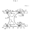
- FIG. 1 An embodiment of a front body structure of a vehicle according to the present invention will be described with reference to Figs. 1 to 8 .
- Arrows FR indicate the front direction of the vehicle, and Arrows UP indicate the upper direction thereof.
- a pair of right and left front side members 10, 12 are disposed at a front portion of a vehicle body along the longitudinal direction thereof.
- a front bumper (not shown) is suspended between front ends 10A, 12A of the front side members 10, 12.
- a front suspension member 20 serving as a connecting member is suspended between front portions of the pair of right and left front side members 10, 12.
- the front suspension member 20 is structured such that a front cross member 26 and a rear cross member 28 are suspended between two linear side rails 22, 24 extending along the longitudinal direction of the vehicle.
- the front cross member 26 is shaped in an arc bulging toward the rear side of the vehicle, in a plan view.
- the rear cross member 28 is shaped in an arc bulging considerably toward the front side of the vehicle, in a plan view.
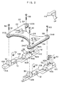
- Front mounting brackets 30, 32 are respectively disposed on lower surfaces 10B, 12B of the front portions of the pair of right and left front side members 10, 12. Front ends 22A, 24A of the side rails 22, 24 are respectively fixed to the front mounting brackets 30, 32 by bolts 38, 40, which respectively pass through front rubber mounts 34, 36 fitting in the front ends 22A, 24A of the side rails 22, 24.
- Rear mounting brackets 50, 52 serving as fixing mechanisms are respectively disposed on lower surfaces 10C, 12C of rear portions of the pair of right and left front side members 10, 12.
- Rear ends 22B, 24B of the side rails 22, 24 are respectively fixed to the rear mounting brackets 50, 52 by bolts 58, 60, which respectively pass through rear rubber mounts 54, 56 fitting in the rear ends 22B, 24B of the side rails 22, 24.
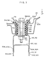
- each of the rear rubber mounts 54, 56 has a well-known structure in which an inner pipe 62 is connected to an outer ring 64 via an elastic member 66.
- a center ring 68 for adjusting the spring constant is embedded in the elastic member 66.
- the front suspension member 20 has a closed cross-sectional structure in which an upper panel 20A and a lower panel 20B are integrally welded.
- Each of the rear mounting brackets 50, 52 is formed by bending a plate member and extends along the longitudinal direction of the vehicle body.
- the cross-sectional shape of the rear mounting brackets 50, 52 viewed from the longitudinal direction of the vehicle is a squared U-shape whose opening is oriented to the upper side of the vehicle.
- Upper edges of side walls 50A, 52A are respectively welded to side walls 10D, 12D of the front side members 10, 12.
- Reference numeral 72 indicates a nut into which the bolt 58 or 60 is screwed
- Reference numeral 74 indicates a washer
- slits 82 opening toward the rear side of the vehicle are respectively formed in bottom walls 50B, 52B of the rear mounting brackets 50, 52.
- Branches 82B (first branches) branching toward the inner rear side of the vehicle are respectively formed near rear-end openings 82A of the slits 82.
- the collided front side member 10 receives a part of the collision load and is deformed so that a part of the impact can be absorbed.
- the front suspension member 20 receives a part of the collision load and is deformed so that a part of the impact can be absorbed.
- the spring constant of the front suspension member 20 along the longitudinal direction of the vehicle is determined as K3
- the front suspension member 20 can be used as a connecting member, there is no need to provide a particular connecting member and the structure is thus simplified.
- the bolts 58, 60 are fit into the branches 82B of the slits 82 formed in the rear mounting brackets 50, 52 serving as fixing mechanisms.
- bolt-movement restraint mechanisms 82C for restraining the movement of the bolts 58, 60, such as irregular surfaces or large friction surfaces, are formed in inner peripheral surfaces of the slits 82, as shown in Fig. 8 .
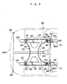
- collision detection sensors 86, 88 are respectively disposed near both ends of a front portion 84A of a vehicle body 84 in the transverse direction of the vehicle, and lock bars 92 serving as lock mechanisms, which open and close the opening ends 82A of the slits 82 of the rear mounting brackets 50, 52 due to operation of actuators 90, are respectively disposed near the opening ends of the slits 82.
- the actuator 90 of the offset-collided front side member 10 is operated by a controller 94 based on detection signals from the collision detection sensors 86, 88, and the lock bar 92 is thereby rotated in Arrow C direction so as to move from a position where the opening end 82A of the slit 82 is opened (illustrated by solid lines in Fig. 9 ) to a lock position where the opening end 82A of the slit 82 is closed (illustrated by two-dotted chain lines in Fig. 9 ).
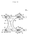
- the branches 82B branching toward the inner rear sides of the vehicle and branches 82D (second branches) branching toward the outer rear sides of the vehicle are respectively formed near the rear-end openings 82A of the slits 82.
- the bolt 58 has passed through the rear-end opening 82A of the slit 82 in the offset-collided front side member 10
- the bolt 60 fits into the branch 82D of the slit 82 in the other front side member 12 so that the impact absorption effect at the time of offset collision can be prevented from being reduced.
- the front suspension member 20 is used as a connecting member.
- the connecting member is not limited to the front suspension member, and may be another member such as a front sub-frame or an engine, or a special member.
- the present invention can provide a front body structure of a vehicle, which has an advantage that satisfactory impact absorption can be achieved both at the time of offset collision and at the time of full-lapped collision.
Landscapes
- Engineering & Computer Science (AREA)
- Chemical & Material Sciences (AREA)
- Combustion & Propulsion (AREA)
- Transportation (AREA)
- Mechanical Engineering (AREA)
- Body Structure For Vehicles (AREA)
Claims (6)
- Structure de corps avant d'un véhicule, comportant :une paire d'éléments latéraux avant droit et gauche (10, 12) disposés au niveau d'une partie avant d'un corps de véhicule le long d'une direction longitudinale du corps de véhicule;un élément de raccordement (20) dans une direction transversale du véhicule, comprenant des extrémités avant (22A, 24A) et des extrémités arrière (22B, 24B), les extrémités avant (22A, 24A) et les extrémités arrière (22B, 24B) étant fixées de manière respective sur des parties de fixation avant (10B, 12B) et des parties de fixation arrière (10C, 12C) de la paire d'éléments latéraux avant droit et gauche (10, 12) ; etdes mécanismes de fixation (50, 52) disposés sur les parties de fixation arrière droite et gauche (10C, 12C), qui comprennent des fentes (82) s'étendant parallèlement aux éléments latéraux avant (10, 12),caractérisée en ce que
les mécanismes de fixation (50, 52) comprennent en outre des premières branches (82B) partant depuis des voisinages d'ouvertures d'extrémité arrière (82A) des fentes (82) vers des côtés arrière intérieurs du véhicule,
des éléments de fixation (58 60, 72) de l'élément de raccordement (20) pouvant se déplacer dans les fentes (82) et les premières branches (82B), et
les premières branches (82B) étant structurées de telle sorte que, au moment d'une collision décalée, les éléments de fixation (58 ou 60, et 72) qui fixent l'élément de raccordement (20) sur l'élément latéral avant en collision (10 ou 12) se déplacent et se logent dans la première branche (82B) de la fente (82),
de telle sorte que les mécanismes de fixation (50, 52) libèrent, quand une charge appliquée sur les éléments latéraux avant (10, 12) depuis un côté avant du véhicule est égale ou supérieure à une valeur prédéterminée au moment d'une collision frontale, un état dans lequel les éléments latéraux avant (10, 12) sont fixés sur l'élément de raccordement (20), et maintiennent, au moment d'une collision décalée, un état dans lequel l'élément latéral avant en collision (10 ou 12) est fixé sur l'élément de raccordement (20). - Structure de corps avant d'un véhicule selon la revendication 1, dans laquelle l'élément de raccordement (20) est un élément de suspension avant (20).
- Structure de corps avant d'un véhicule selon la revendication 1, dans laquelle les fentes (82) comprennent en outre des deuxièmes branches (82D) partant vers des côtés extérieurs arrière du véhicule.
- Structure de corps avant d'un véhicule selon la revendication 3, dans laquelle les deuxièmes branches (82D) sont structurées de telle sorte que, au moment d'une collision décalée, les éléments de fixation (58 ou 60, et 72) qui fixent l'élément de raccordement (20) sur l'autre élément latéral avant (10 ou 12) à l'opposé de l'élément latéral avant en collision (10 ou 12) se déplacent et se logent dans la deuxième branche (82D) de la fente (82).
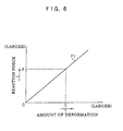
- Structure de corps avant d'un véhicule selon la revendication 1, structurée de telle sorte qu'une force de réaction (F1) des éléments latéraux avant droit et gauche (10, 12) au moment d'une collision frontale devient sensiblement égale à une force de réaction totale (F5) au moment d'une collision décalée.
- Structure de corps avant d'un véhicule selon la revendication 5, structurée de telle sorte que, au moment d'une collision décalée, l'élément de raccordement (20) reçoit une partie de la charge de collision que l'élément latéral avant en collision (10 ou 12) reçoit de telle sorte qu'une partie de l'impact peut être absorbée.
Applications Claiming Priority (3)
| Application Number | Priority Date | Filing Date | Title |
|---|---|---|---|
| JP2002376242 | 2002-12-26 | ||
| JP2002376242A JP4144350B2 (ja) | 2002-12-26 | 2002-12-26 | 車両のフロントボデー構造 |
| PCT/JP2003/015806 WO2004058559A1 (fr) | 2002-12-26 | 2003-12-10 | Structure de corps avant de vehicule |
Publications (3)
| Publication Number | Publication Date |
|---|---|
| EP1577196A1 EP1577196A1 (fr) | 2005-09-21 |
| EP1577196A4 EP1577196A4 (fr) | 2006-05-17 |
| EP1577196B1 true EP1577196B1 (fr) | 2008-03-19 |
Family
ID=32677359
Family Applications (1)
| Application Number | Title | Priority Date | Filing Date |
|---|---|---|---|
| EP03780703A Expired - Lifetime EP1577196B1 (fr) | 2002-12-26 | 2003-12-10 | Structure de corps avant de vehicule |
Country Status (6)
| Country | Link |
|---|---|
| US (1) | US7380829B2 (fr) |
| EP (1) | EP1577196B1 (fr) |
| JP (1) | JP4144350B2 (fr) |
| CN (1) | CN100390008C (fr) |
| DE (1) | DE60319874T2 (fr) |
| WO (1) | WO2004058559A1 (fr) |
Families Citing this family (66)
| Publication number | Priority date | Publication date | Assignee | Title |
|---|---|---|---|---|
| DE102004005571B4 (de) * | 2004-02-05 | 2008-07-10 | Daimler Ag | Verbindungsbereich zur Anbindung eines Anbauteils an eine Fahrzeugkarosserie |
| JP4649849B2 (ja) * | 2004-03-02 | 2011-03-16 | トヨタ自動車株式会社 | 蓄電機構の取付構造 |
| JP4231473B2 (ja) * | 2004-10-19 | 2009-02-25 | 本田技研工業株式会社 | ステアリングギヤボックス取付構造 |
| FR2887211B1 (fr) * | 2005-06-20 | 2007-09-07 | Vallourec Vitry | Voie basse guidee pour avant de vehicule automobile |
| JP4478654B2 (ja) * | 2006-02-13 | 2010-06-09 | 本田技研工業株式会社 | 車体フロア構造 |
| JP5141026B2 (ja) * | 2006-02-27 | 2013-02-13 | トヨタ自動車株式会社 | 蓄電パックの車載構造 |
| JP4804969B2 (ja) * | 2006-03-16 | 2011-11-02 | 本田技研工業株式会社 | 燃料電池自動車の前部構造 |
| US20070251751A1 (en) * | 2006-05-01 | 2007-11-01 | Textron Inc. | Cast Aluminum Frame Component for Golf Cars and Small Utility Vehicles |
| US7717465B2 (en) * | 2007-01-11 | 2010-05-18 | Ford Motor Company | Vehicle having an engine support structure |
| KR101065234B1 (ko) * | 2007-02-01 | 2011-09-16 | 도요타 지도샤(주) | 차량 단부 구조 |
| JP4479740B2 (ja) * | 2007-03-23 | 2010-06-09 | 日産自動車株式会社 | 車体前部構造及び車体前部配管固定用ブラケット |
| JP4901688B2 (ja) * | 2007-10-17 | 2012-03-21 | 本田技研工業株式会社 | 車体前部構造 |
| JP4585585B2 (ja) | 2008-08-06 | 2010-11-24 | 本田技研工業株式会社 | 車体構造 |
| KR20100045800A (ko) * | 2008-10-24 | 2010-05-04 | 현대자동차주식회사 | 서스펜션용 서브 프레임 |
| JP4878646B2 (ja) * | 2009-05-28 | 2012-02-15 | 本田技研工業株式会社 | 車体後部構造 |
| US8308193B2 (en) * | 2010-02-26 | 2012-11-13 | Honda Motor Co., Ltd. | Vehicle frame assembly and method |
| US8348333B2 (en) * | 2010-06-10 | 2013-01-08 | C.R.F. SOCIETá CONSORTILE PER AZIONI | Motor-vehicle structure having a front module constituted by elements made of plastic and/or composite material |
| JP5867027B2 (ja) * | 2011-11-29 | 2016-02-24 | スズキ株式会社 | サスペンションフレームの周辺構造 |
| FR2984839A1 (fr) * | 2011-12-22 | 2013-06-28 | Peugeot Citroen Automobiles Sa | Interface de fixation d'un plancher pour fixation d'un berceau moteur de vehicule et vehicule presentant une telle interface. |
| JP5468101B2 (ja) * | 2012-03-27 | 2014-04-09 | 富士重工業株式会社 | 車体前部構造 |
| DE102012009567A1 (de) * | 2012-05-10 | 2013-11-14 | Audi Ag | Achsträgeranordnung an einem Fahrzeug,insbesondere an einem Kraftfahrzeug |
| US8851520B2 (en) * | 2012-10-22 | 2014-10-07 | Honda Motor Co., Ltd. | Front subframe for a narrow offset collision |
| FR2997673B1 (fr) * | 2012-11-08 | 2016-08-26 | Peugeot Citroen Automobiles Sa | Cadre support pour groupe electro-propulseur pourvu d'organes de repartition d'effort de choc |
| US8746741B2 (en) * | 2012-11-14 | 2014-06-10 | The United States Of America As Represented By The Secretary Of The Army | Truncated V underbody protection enhancement |
| JP5713033B2 (ja) * | 2013-01-21 | 2015-05-07 | トヨタ自動車株式会社 | 車両構造 |
| JP5790714B2 (ja) * | 2013-06-20 | 2015-10-07 | トヨタ自動車株式会社 | 車両下部構造 |
| JP6077402B2 (ja) * | 2013-06-28 | 2017-02-08 | 富士重工業株式会社 | 車体前部構造 |
| MX2016000338A (es) * | 2013-07-11 | 2016-05-05 | F Tech Inc | Sub-bastidor para vehiculo. |
| KR101526748B1 (ko) | 2013-12-18 | 2015-06-05 | 현대자동차주식회사 | 충돌 하중을 저감 시키는 충전구 브라켓 |
| ES2609932T3 (es) * | 2014-02-03 | 2017-04-25 | Autotech Engineering Deutschland GmbH | Falso chasis para un automóvil, en particular falso chasis de eje delantero, y carrocería con un falso chasis de este tipo |
| JP6063406B2 (ja) * | 2014-03-06 | 2017-01-18 | 本田技研工業株式会社 | 燃料電池スタックのマウント構造 |
| KR101542995B1 (ko) * | 2014-04-15 | 2015-08-07 | 현대자동차 주식회사 | 차량용 쇽 업소버 하우징 및 그 장착구조 |
| CN104828140B (zh) * | 2014-07-08 | 2017-08-04 | 北汽福田汽车股份有限公司 | 前副车架及安装支架总成和具有它的车辆 |
| JP6344118B2 (ja) * | 2014-07-28 | 2018-06-20 | スズキ株式会社 | サスペンションフレーム構造 |
| KR101575335B1 (ko) * | 2014-08-13 | 2015-12-07 | 현대자동차 주식회사 | 전방 차체 보강구조 |
| JP6044796B2 (ja) * | 2014-08-29 | 2016-12-14 | マツダ株式会社 | 車両の前部車体構造 |
| SE540075C2 (en) * | 2015-05-19 | 2018-03-13 | Ningbo Geely Automobile Res & Development Co Ltd | Sub-frame method and arrangement for releasing a front section of the sub-frame |
| KR101703596B1 (ko) * | 2015-07-24 | 2017-02-07 | 현대자동차 주식회사 | 전방 차체 구조 |
| US9616931B2 (en) | 2015-09-16 | 2017-04-11 | GM Global Technology Operations LLC | Releasable cradle to body joint |
| JP6264352B2 (ja) * | 2015-09-29 | 2018-01-24 | トヨタ自動車株式会社 | サスペンションメンバのロアアームブラケット構造 |
| JP6269636B2 (ja) * | 2015-11-10 | 2018-01-31 | マツダ株式会社 | リヤサブフレーム構造 |
| US9676418B1 (en) * | 2016-01-15 | 2017-06-13 | Fca Us Llc | Vehicle crossmember assembly with pedestal detachment |
| DE102017200984B4 (de) * | 2016-02-01 | 2024-09-05 | Ford Global Technologies, Llc | Kraftfahrzeug mit Hilfsrahmen und wenigstens einem Hilfsrahmenlager |
| US10081245B2 (en) * | 2016-06-24 | 2018-09-25 | GM Global Technology Operations LLC | Cradle to body joint release mechanism |
| KR101765640B1 (ko) * | 2016-07-18 | 2017-08-23 | 현대자동차 주식회사 | 서브 프레임용 마운팅 유닛 |
| US10703413B2 (en) * | 2016-08-31 | 2020-07-07 | Ford Global Technologies, Llc | Rear drive unit detachment system and method |
| DE102016223946A1 (de) * | 2016-12-01 | 2018-06-07 | Bayerische Motoren Werke Aktiengesellschaft | Halteanordnung eines Vorderachsträgers an wenigstens einem Längsträger eines Personenkraftwagens |
| US10370035B2 (en) * | 2016-12-08 | 2019-08-06 | Inevit Llc | Motor guidance component configured to direct movement of a dislodged electric motor of an electric vehicle in response to crash forces |
| DE102016125335B3 (de) * | 2016-12-22 | 2017-12-28 | Benteler Automobiltechnik Gmbh | Verstärkungsstrebe für ein Kraftfahrzeug |
| JP6900768B2 (ja) * | 2017-04-28 | 2021-07-07 | トヨタ自動車株式会社 | 車両前部構造 |
| JP6819476B2 (ja) * | 2017-06-16 | 2021-01-27 | トヨタ自動車株式会社 | 車両前部構造 |
| US20190118632A1 (en) * | 2017-10-23 | 2019-04-25 | Ford Global Technologies, Llc | Vehicle and powertrain component mounting system |
| KR101977529B1 (ko) * | 2018-01-17 | 2019-08-28 | 지엠 글로벌 테크놀러지 오퍼레이션스 엘엘씨 | 횡 방향 움직임의 증가를 위한 크로스 부재를 포함하는 전기 자동차 |
| JP7024589B2 (ja) * | 2018-05-10 | 2022-02-24 | トヨタ自動車株式会社 | 電気機器の車載構造 |
| US10703415B2 (en) * | 2018-06-08 | 2020-07-07 | Ford Global Technologies, Llc | Vehicle frame assembly |
| SG11202111702VA (en) * | 2019-05-15 | 2021-11-29 | Trinity Highway Products Llc | Crash attenuator with release plate hinge assembly, release plate hinge assembly and method for the use thereof |
| US11286001B2 (en) * | 2019-09-05 | 2022-03-29 | Fca Us Llc | Angled cross member for a vehicle |
| US11299206B2 (en) * | 2019-09-12 | 2022-04-12 | GM Global Technology Operations LLC | Vehicle structure for a cross-vehicle load path |
| JP7197524B2 (ja) * | 2020-01-14 | 2022-12-27 | トヨタ自動車株式会社 | 自動車ボデーの前部構造 |
| US11390327B2 (en) | 2020-04-14 | 2022-07-19 | Toyota Motor Engineering & Manufacturing North America, Inc. | Subframe brace apparatus and related assemblies for use with vehicles |
| KR102829341B1 (ko) * | 2020-05-19 | 2025-07-03 | 현대자동차주식회사 | 전기차량용 차체 |
| GB2598571B (en) * | 2020-09-02 | 2023-06-07 | Jaguar Land Rover Ltd | Modular crash structure for a vehicle |
| US11623690B2 (en) | 2020-10-20 | 2023-04-11 | Ford Global Technologies, Llc | Cross members on rear rails in a unibody truck |
| CN114426062A (zh) * | 2022-02-09 | 2022-05-03 | 奇瑞汽车股份有限公司 | 副车架焊接总成和车辆 |
| EP4299420A1 (fr) * | 2022-07-01 | 2024-01-03 | Autotech Engineering S.L. | Châssis auxiliaire pour un véhicule, en particulier véhicule électrique |
| JP2024054026A (ja) * | 2022-10-04 | 2024-04-16 | 株式会社Subaru | 車体前部構造 |
Family Cites Families (17)
| Publication number | Priority date | Publication date | Assignee | Title |
|---|---|---|---|---|
| DE3912501A1 (de) * | 1989-04-17 | 1990-10-18 | Daimler Benz Ag | Anordnung eines hinterachstraegers an der karosserieunterseite eines personenkraftwagens |
| JPH08164869A (ja) * | 1994-12-15 | 1996-06-25 | Fuji Heavy Ind Ltd | 車両の前部フレーム構造 |
| JP3458674B2 (ja) * | 1997-10-09 | 2003-10-20 | 日産自動車株式会社 | フロントサイドメンバ根元部構造 |
| JP3954709B2 (ja) | 1997-12-12 | 2007-08-08 | 本田技研工業株式会社 | 車両におけるサブフレーム支持構造 |
| JP3464756B2 (ja) * | 1997-12-12 | 2003-11-10 | 本田技研工業株式会社 | 車両における衝撃吸収車体構造 |
| JPH11198854A (ja) | 1998-01-09 | 1999-07-27 | Nissan Motor Co Ltd | 自動車のフロントクロスメンバ構造 |
| JP3089472B2 (ja) * | 1999-02-19 | 2000-09-18 | 本田技研工業株式会社 | フロントサブフレーム構造 |
| JP3765234B2 (ja) | 2001-02-14 | 2006-04-12 | 日産自動車株式会社 | 車体前部構造 |
| EP1245477B1 (fr) * | 2001-03-28 | 2007-09-05 | Fuji Jukogyo Kabushiki Kaisha | Structure de support d'un châssis auxiliaire d'un système de suspension d'un véhicule |
| JP3575439B2 (ja) * | 2001-06-04 | 2004-10-13 | 日産自動車株式会社 | 自動車のパワーユニット配置構造 |
| JP3900048B2 (ja) * | 2001-11-19 | 2007-04-04 | 日産自動車株式会社 | 車体前部構造 |
| US6742808B1 (en) * | 2001-12-10 | 2004-06-01 | Hayes Lemmerz International, Inc. | Cast aluminum vehicle subframe with tension/compression struts |
| JP4010169B2 (ja) * | 2002-04-09 | 2007-11-21 | 三菱自動車工業株式会社 | 車体構造 |
| JP4122887B2 (ja) * | 2002-08-05 | 2008-07-23 | 日産自動車株式会社 | 車体前部構造 |
| JP3842204B2 (ja) * | 2002-11-11 | 2006-11-08 | 本田技研工業株式会社 | 前部車体構造 |
| JP4403719B2 (ja) * | 2003-05-12 | 2010-01-27 | トヨタ自動車株式会社 | 車両、及び乗員保護装置の起動制御装置 |
| JP4103834B2 (ja) * | 2004-04-06 | 2008-06-18 | 日産自動車株式会社 | 車体前部構造 |
-
2002
- 2002-12-26 JP JP2002376242A patent/JP4144350B2/ja not_active Expired - Fee Related
-
2003
- 2003-12-10 EP EP03780703A patent/EP1577196B1/fr not_active Expired - Lifetime
- 2003-12-10 CN CNB2003801074708A patent/CN100390008C/zh not_active Expired - Fee Related
- 2003-12-10 DE DE60319874T patent/DE60319874T2/de not_active Expired - Lifetime
- 2003-12-10 WO PCT/JP2003/015806 patent/WO2004058559A1/fr not_active Ceased
- 2003-12-10 US US10/537,807 patent/US7380829B2/en not_active Expired - Fee Related
Also Published As
| Publication number | Publication date |
|---|---|
| US20060113784A1 (en) | 2006-06-01 |
| JP2004203274A (ja) | 2004-07-22 |
| WO2004058559A1 (fr) | 2004-07-15 |
| EP1577196A4 (fr) | 2006-05-17 |
| JP4144350B2 (ja) | 2008-09-03 |
| CN100390008C (zh) | 2008-05-28 |
| DE60319874T2 (de) | 2009-04-23 |
| CN1732105A (zh) | 2006-02-08 |
| EP1577196A1 (fr) | 2005-09-21 |
| DE60319874D1 (de) | 2008-04-30 |
| US7380829B2 (en) | 2008-06-03 |
Similar Documents
| Publication | Publication Date | Title |
|---|---|---|
| EP1577196B1 (fr) | Structure de corps avant de vehicule | |
| US8132845B2 (en) | Vehicle door structure | |
| US6575525B2 (en) | Reinforced door frame for a motor vehicle | |
| US7216924B2 (en) | Body to frame energy transfer brackets | |
| EP1465785B1 (fr) | Porte de vehicule | |
| US20080290693A1 (en) | Device for Protecting Passengers in a Motor Vehicle in the Event of Energy Input Caused by a Collision and Oriented at the Motor Vehicle Door | |
| JPH11310036A (ja) | 車両用側部ドア構造 | |
| US7118126B2 (en) | Side airbag deployment signal enhancement | |
| JP3331861B2 (ja) | 側面衝突センサの取付構造 | |
| US6957844B2 (en) | Mounting plate for vehicle door reinforcement members | |
| JP4188141B2 (ja) | 車両用ドアの補強構造 | |
| JP4917976B2 (ja) | 車両用ドア構造 | |
| JP3446655B2 (ja) | 車両用bピラー下部構造 | |
| KR100196410B1 (ko) | 자동차 측면 충돌시 도어 침입차단장치 | |
| KR100828804B1 (ko) | 차량의 도어 밀림방지용 후크구조 | |
| JPH0732945A (ja) | 自動車の乗員保護装置 | |
| KR200152952Y1 (ko) | 자동차 도어의 임팩트바 취부구조물 | |
| KR100315360B1 (ko) | 자동차용 시트의 측면 충돌 대응용 스토퍼 | |
| KR200140912Y1 (ko) | 차량용 시트 프레임 | |
| JP2000318527A (ja) | 車両のステップ | |
| KR970005728A (ko) | 자동차용 도어의 보강재 취부구조 | |
| JP2000142283A (ja) | 車両用側面衝突検知センサの取付構造 | |
| KR0139456B1 (ko) | 자동차 도어의 임팩트 빔 고정구조 | |
| KR0119211Y1 (ko) | 도어 로크 스트라이커 고정구 | |
| KR200159443Y1 (ko) | 자동차의 센터필러 밀림방지구조 |
Legal Events
| Date | Code | Title | Description |
|---|---|---|---|
| PUAI | Public reference made under article 153(3) epc to a published international application that has entered the european phase |
Free format text: ORIGINAL CODE: 0009012 |
|
| 17P | Request for examination filed |
Effective date: 20050609 |
|
| AK | Designated contracting states |
Kind code of ref document: A1 Designated state(s): AT BE BG CH CY CZ DE DK EE ES FI FR GB GR HU IE IT LI LU MC NL PT RO SE SI SK TR |
|
| RBV | Designated contracting states (corrected) |
Designated state(s): DE FR GB IT |
|
| A4 | Supplementary search report drawn up and despatched |
Effective date: 20060331 |
|
| RIC1 | Information provided on ipc code assigned before grant |
Ipc: B62D 21/15 20060101AFI20060327BHEP Ipc: B62D 21/11 20060101ALI20060327BHEP |
|
| 17Q | First examination report despatched |
Effective date: 20070329 |
|
| GRAP | Despatch of communication of intention to grant a patent |
Free format text: ORIGINAL CODE: EPIDOSNIGR1 |
|
| GRAS | Grant fee paid |
Free format text: ORIGINAL CODE: EPIDOSNIGR3 |
|
| GRAA | (expected) grant |
Free format text: ORIGINAL CODE: 0009210 |
|
| AK | Designated contracting states |
Kind code of ref document: B1 Designated state(s): DE FR GB IT |
|
| REG | Reference to a national code |
Ref country code: GB Ref legal event code: FG4D |
|
| REF | Corresponds to: |
Ref document number: 60319874 Country of ref document: DE Date of ref document: 20080430 Kind code of ref document: P |
|
| ET | Fr: translation filed | ||
| PLBE | No opposition filed within time limit |
Free format text: ORIGINAL CODE: 0009261 |
|
| STAA | Information on the status of an ep patent application or granted ep patent |
Free format text: STATUS: NO OPPOSITION FILED WITHIN TIME LIMIT |
|
| 26N | No opposition filed |
Effective date: 20081222 |
|
| REG | Reference to a national code |
Ref country code: GB Ref legal event code: 746 Effective date: 20120917 |
|
| REG | Reference to a national code |
Ref country code: DE Ref legal event code: R084 Ref document number: 60319874 Country of ref document: DE Effective date: 20120924 |
|
| PGFP | Annual fee paid to national office [announced via postgrant information from national office to epo] |
Ref country code: GB Payment date: 20141210 Year of fee payment: 12 Ref country code: DE Payment date: 20141202 Year of fee payment: 12 |
|
| PGFP | Annual fee paid to national office [announced via postgrant information from national office to epo] |
Ref country code: FR Payment date: 20141208 Year of fee payment: 12 |
|
| PGFP | Annual fee paid to national office [announced via postgrant information from national office to epo] |
Ref country code: IT Payment date: 20141127 Year of fee payment: 12 |
|
| REG | Reference to a national code |
Ref country code: DE Ref legal event code: R119 Ref document number: 60319874 Country of ref document: DE |
|
| GBPC | Gb: european patent ceased through non-payment of renewal fee |
Effective date: 20151210 |
|
| REG | Reference to a national code |
Ref country code: FR Ref legal event code: ST Effective date: 20160831 |
|
| PG25 | Lapsed in a contracting state [announced via postgrant information from national office to epo] |
Ref country code: DE Free format text: LAPSE BECAUSE OF NON-PAYMENT OF DUE FEES Effective date: 20160701 Ref country code: GB Free format text: LAPSE BECAUSE OF NON-PAYMENT OF DUE FEES Effective date: 20151210 |
|
| PG25 | Lapsed in a contracting state [announced via postgrant information from national office to epo] |
Ref country code: FR Free format text: LAPSE BECAUSE OF NON-PAYMENT OF DUE FEES Effective date: 20151231 |
|
| PG25 | Lapsed in a contracting state [announced via postgrant information from national office to epo] |
Ref country code: IT Free format text: LAPSE BECAUSE OF NON-PAYMENT OF DUE FEES Effective date: 20151210 |