EP1577196B1 - Front body structure of vehicle - Google Patents
Front body structure of vehicle Download PDFInfo
- Publication number
- EP1577196B1 EP1577196B1 EP03780703A EP03780703A EP1577196B1 EP 1577196 B1 EP1577196 B1 EP 1577196B1 EP 03780703 A EP03780703 A EP 03780703A EP 03780703 A EP03780703 A EP 03780703A EP 1577196 B1 EP1577196 B1 EP 1577196B1
- Authority
- EP
- European Patent Office
- Prior art keywords
- vehicle
- front side
- collision
- body structure
- connecting member
- Prior art date
- Legal status (The legal status is an assumption and is not a legal conclusion. Google has not performed a legal analysis and makes no representation as to the accuracy of the status listed.)
- Expired - Lifetime
Links
- 239000000725 suspension Substances 0.000 claims description 26
- 230000007246 mechanism Effects 0.000 claims description 15
- 238000006243 chemical reaction Methods 0.000 claims description 13
- 238000010521 absorption reaction Methods 0.000 description 10
- 230000000052 comparative effect Effects 0.000 description 4
- 230000000694 effects Effects 0.000 description 4
- 238000001514 detection method Methods 0.000 description 3
- 238000005452 bending Methods 0.000 description 1
- 230000005489 elastic deformation Effects 0.000 description 1
- 230000001788 irregular Effects 0.000 description 1
- 230000002093 peripheral effect Effects 0.000 description 1
- 239000004033 plastic Substances 0.000 description 1
- 230000000452 restraining effect Effects 0.000 description 1
Images


Classifications
-
- B—PERFORMING OPERATIONS; TRANSPORTING
- B62—LAND VEHICLES FOR TRAVELLING OTHERWISE THAN ON RAILS
- B62D—MOTOR VEHICLES; TRAILERS
- B62D21/00—Understructures, i.e. chassis frame on which a vehicle body may be mounted
- B62D21/15—Understructures, i.e. chassis frame on which a vehicle body may be mounted having impact absorbing means, e.g. a frame designed to permanently or temporarily change shape or dimension upon impact with another body
- B62D21/152—Front or rear frames
- B62D21/155—Sub-frames or underguards
Definitions
- the present invention relates to a front body structure of a vehicle, and specifically to a front body structure of a vehicle for reducing the impact acting on occupants at the time when the vehicle such as an automobile comes into frontal collision.
- a front sub-frame is supported by bolts to brackets which are fixed to a main frame and in which rear-end opening slits are formed, and the bolts on the rear side slip from the rear-end openings of the slits at the time of frontal collision. Accordingly, the main frame can be crushed without the interruption of the front sub-frame.
- JP-A Japanese Patent Application Laid-Open
- a front cross member extending on a front edge of the vehicle along the transverse direction thereof is divided at a substantially central portion of the front cross member into right and left two cross members, and a compass mechanism for symmetrically restricting the rotational movement of the right and left cross members with the respective substantially central portions thereof being as a rotational center is provided at a connecting portion between the right and left cross members.
- This structure is disclosed in, for example, JP-A No. 11-198854 .
- JP-A No. 11-171046 even when the vehicle comes into offset collision, the right and left bolts on the rear side slip from the rear-end openings of the slits, and the impact is absorbed only by the collided front side member. Therefore, the amount of impact absorption in the case of offset collision is less than that in the case of full-lapped collision (full collision), and satisfactory impact absorption cannot be achieved. Further, in the structure of JP-A No. 11-198854 , the satisfactory impact absorption is limited by the problem of strength of the compass mechanism against a large collision load.
- an object of the present invention is to obtain a front body structure of a vehicle, in which satisfactory impact absorption can be achieved both at the time of offset collision and at the time of full-lapped collision.
- the front body structure of a vehicle comprises: a pair of right and left front side members disposed at a front portion of a vehicle body along a longitudinal direction of the vehicle body; a connecting member including front ends and rear ends in a transverse direction of the vehicle, the front ends and the rear ends being respectively fixed to front fixing portions and rear fixing portions of the pair of right and left front side members; and fixing mechanisms disposed on the right and left rear fixing portions, the fixing mechanisms releasing, when a load applied to the front side members from a front side of the vehicle is equal to or more than a predetermined value at a time of full-lapped collision, a state in which the front side members are fixed to the connecting member, and maintaining, at a time of offset collision, a state in which the collided front side member is fixed to the connecting member.
- the state in which the collided front side member is fixed to the connecting member is maintained by the fixing mechanism disposed at the rear fixing portions of the collided front side member and the connecting member.
- the collided front side member receives a part of the load and is deformed so that the impact can be absorbed
- the fixing mechanism also receives a part of the load and is deformed so that the impact can be absorbed.
- the other front side member also receives a part of the load via the fixing mechanism and is deformed so that the impact can be absorbed.
- the connecting member may be a front suspension member.
- the front suspension member can be used as the connecting member, there is no need to provide a particular connecting member and the structure is thus simplified.
- FIG. 1 An embodiment of a front body structure of a vehicle according to the present invention will be described with reference to Figs. 1 to 8 .
- Arrows FR indicate the front direction of the vehicle, and Arrows UP indicate the upper direction thereof.
- a pair of right and left front side members 10, 12 are disposed at a front portion of a vehicle body along the longitudinal direction thereof.
- a front bumper (not shown) is suspended between front ends 10A, 12A of the front side members 10, 12.
- a front suspension member 20 serving as a connecting member is suspended between front portions of the pair of right and left front side members 10, 12.
- the front suspension member 20 is structured such that a front cross member 26 and a rear cross member 28 are suspended between two linear side rails 22, 24 extending along the longitudinal direction of the vehicle.
- the front cross member 26 is shaped in an arc bulging toward the rear side of the vehicle, in a plan view.
- the rear cross member 28 is shaped in an arc bulging considerably toward the front side of the vehicle, in a plan view.
- Front mounting brackets 30, 32 are respectively disposed on lower surfaces 10B, 12B of the front portions of the pair of right and left front side members 10, 12. Front ends 22A, 24A of the side rails 22, 24 are respectively fixed to the front mounting brackets 30, 32 by bolts 38, 40, which respectively pass through front rubber mounts 34, 36 fitting in the front ends 22A, 24A of the side rails 22, 24.
- Rear mounting brackets 50, 52 serving as fixing mechanisms are respectively disposed on lower surfaces 10C, 12C of rear portions of the pair of right and left front side members 10, 12.
- Rear ends 22B, 24B of the side rails 22, 24 are respectively fixed to the rear mounting brackets 50, 52 by bolts 58, 60, which respectively pass through rear rubber mounts 54, 56 fitting in the rear ends 22B, 24B of the side rails 22, 24.
- each of the rear rubber mounts 54, 56 has a well-known structure in which an inner pipe 62 is connected to an outer ring 64 via an elastic member 66.
- a center ring 68 for adjusting the spring constant is embedded in the elastic member 66.
- the front suspension member 20 has a closed cross-sectional structure in which an upper panel 20A and a lower panel 20B are integrally welded.
- Each of the rear mounting brackets 50, 52 is formed by bending a plate member and extends along the longitudinal direction of the vehicle body.
- the cross-sectional shape of the rear mounting brackets 50, 52 viewed from the longitudinal direction of the vehicle is a squared U-shape whose opening is oriented to the upper side of the vehicle.
- Upper edges of side walls 50A, 52A are respectively welded to side walls 10D, 12D of the front side members 10, 12.
- Reference numeral 72 indicates a nut into which the bolt 58 or 60 is screwed
- Reference numeral 74 indicates a washer
- slits 82 opening toward the rear side of the vehicle are respectively formed in bottom walls 50B, 52B of the rear mounting brackets 50, 52.
- Branches 82B (first branches) branching toward the inner rear side of the vehicle are respectively formed near rear-end openings 82A of the slits 82.
- the collided front side member 10 receives a part of the collision load and is deformed so that a part of the impact can be absorbed.
- the front suspension member 20 receives a part of the collision load and is deformed so that a part of the impact can be absorbed.
- the spring constant of the front suspension member 20 along the longitudinal direction of the vehicle is determined as K3
- the front suspension member 20 can be used as a connecting member, there is no need to provide a particular connecting member and the structure is thus simplified.
- the bolts 58, 60 are fit into the branches 82B of the slits 82 formed in the rear mounting brackets 50, 52 serving as fixing mechanisms.
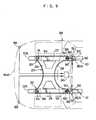
- bolt-movement restraint mechanisms 82C for restraining the movement of the bolts 58, 60, such as irregular surfaces or large friction surfaces, are formed in inner peripheral surfaces of the slits 82, as shown in Fig. 8 .
- collision detection sensors 86, 88 are respectively disposed near both ends of a front portion 84A of a vehicle body 84 in the transverse direction of the vehicle, and lock bars 92 serving as lock mechanisms, which open and close the opening ends 82A of the slits 82 of the rear mounting brackets 50, 52 due to operation of actuators 90, are respectively disposed near the opening ends of the slits 82.
- the actuator 90 of the offset-collided front side member 10 is operated by a controller 94 based on detection signals from the collision detection sensors 86, 88, and the lock bar 92 is thereby rotated in Arrow C direction so as to move from a position where the opening end 82A of the slit 82 is opened (illustrated by solid lines in Fig. 9 ) to a lock position where the opening end 82A of the slit 82 is closed (illustrated by two-dotted chain lines in Fig. 9 ).
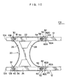
- the branches 82B branching toward the inner rear sides of the vehicle and branches 82D (second branches) branching toward the outer rear sides of the vehicle are respectively formed near the rear-end openings 82A of the slits 82.
- the bolt 58 has passed through the rear-end opening 82A of the slit 82 in the offset-collided front side member 10
- the bolt 60 fits into the branch 82D of the slit 82 in the other front side member 12 so that the impact absorption effect at the time of offset collision can be prevented from being reduced.
- the front suspension member 20 is used as a connecting member.
- the connecting member is not limited to the front suspension member, and may be another member such as a front sub-frame or an engine, or a special member.
- the present invention can provide a front body structure of a vehicle, which has an advantage that satisfactory impact absorption can be achieved both at the time of offset collision and at the time of full-lapped collision.
Description
- The present invention relates to a front body structure of a vehicle, and specifically to a front body structure of a vehicle for reducing the impact acting on occupants at the time when the vehicle such as an automobile comes into frontal collision.
- In a front body structure of a vehicle according to the portion of appended claim 1 for reducing the impact acting on occupants at the time when the vehicle such as an automobile comes into frontal collision, a front sub-frame is supported by bolts to brackets which are fixed to a main frame and in which rear-end opening slits are formed, and the bolts on the rear side slip from the rear-end openings of the slits at the time of frontal collision. Accordingly, the main frame can be crushed without the interruption of the front sub-frame. This structure is disclosed in, for example, Japanese Patent Application Laid-Open (
JP-A) No. 11-171046 - Further, in another front body structure of a vehicle for reducing the impact acting on occupants at the time when the vehicle such as an automobile comes into frontal collision, a front cross member extending on a front edge of the vehicle along the transverse direction thereof is divided at a substantially central portion of the front cross member into right and left two cross members, and a compass mechanism for symmetrically restricting the rotational movement of the right and left cross members with the respective substantially central portions thereof being as a rotational center is provided at a connecting portion between the right and left cross members. This structure is disclosed in, for example,
JP-A No. 11-198854 - However, in the structure of
JP-A No. 11-171046 JP-A No. 11-198854 - In view of the above facts, an object of the present invention is to obtain a front body structure of a vehicle, in which satisfactory impact absorption can be achieved both at the time of offset collision and at the time of full-lapped collision.
- This object is achieved by a front body structure of a vehicle according to appended claim 1.
- In order to solve the above problems, the front body structure of a vehicle according to the present invention comprises: a pair of right and left front side members disposed at a front portion of a vehicle body along a longitudinal direction of the vehicle body; a connecting member including front ends and rear ends in a transverse direction of the vehicle, the front ends and the rear ends being respectively fixed to front fixing portions and rear fixing portions of the pair of right and left front side members; and fixing mechanisms disposed on the right and left rear fixing portions, the fixing mechanisms releasing, when a load applied to the front side members from a front side of the vehicle is equal to or more than a predetermined value at a time of full-lapped collision, a state in which the front side members are fixed to the connecting member, and maintaining, at a time of offset collision, a state in which the collided front side member is fixed to the connecting member.
- When the vehicle comes into full-lapped collision, the state in which the front side members are fixed to the connecting member is released by the fixing mechanisms disposed at the rear fixing portions of the front side members and the connecting member. As a result, the right and left front side members receive the load and are deformed so that the impact can be absorbed.
- On the other hand, when the vehicle comes into offset collision, the state in which the collided front side member is fixed to the connecting member is maintained by the fixing mechanism disposed at the rear fixing portions of the collided front side member and the connecting member. As a result, the collided front side member receives a part of the load and is deformed so that the impact can be absorbed, and the fixing mechanism also receives a part of the load and is deformed so that the impact can be absorbed. Further, the other front side member also receives a part of the load via the fixing mechanism and is deformed so that the impact can be absorbed.
- As a result, even in the case of offset collision, substantially the same impact absorption effect as in the case of full-lapped collision can be obtained, and satisfactory impact absorption can be thus achieved both at the time of offset collision and at the time of full-lapped collision.
- Further, in the front body structure of a vehicle according to the present invention, the connecting member may be a front suspension member.
- Accordingly, since the front suspension member can be used as the connecting member, there is no need to provide a particular connecting member and the structure is thus simplified.
-
-
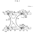
Fig. 1 is a plan view showing a front body structure of a vehicle, according to an embodiment of the present invention, seen from a lower side of the vehicle. -
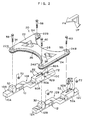
Fig. 2 is an exploded perspective view showing the front body structure of the vehicle, according to the embodiment of the present invention, seen from a lower front side of the vehicle at an angle. -
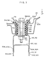
Fig. 3 is an enlarged cross-sectional view seen along Line 3-3 inFig. 1 . -
Fig. 4 is a plan view showing a full-lapped collision state of the front body structure of the vehicle, according to the embodiment of the present invention, seen from the lower side of the vehicle. -
Fig. 5 is a plan view showing an offset collision state of the front body structure of the vehicle, according to the embodiment of the present invention, seen from the lower side of the vehicle. -
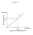
Fig. 6 is a graph showing reaction force characteristics in the full-lapped collision state of the front body structure of the vehicle, according to the embodiment of the present invention. -
Fig. 7 is a graph showing reaction force characteristics in the offset collision state of the front body structure of the vehicle, according to the embodiment of the present invention. -
Fig. 8 is a plan view showing a front body structure of a vehicle, according to a comparative example, seen from a lower side of the vehicle. -
Fig. 9 is a plan view showing a front body structure of a vehicle, according to a comparative example, seen from a lower side of the vehicle. -
Fig. 10 is a plan view showing a front body structure of a vehicle, according to another embodiment of the present invention, seen from a lower side of the vehicle. - An embodiment of a front body structure of a vehicle according to the present invention will be described with reference to
Figs. 1 to 8 . - In these figures, Arrows FR indicate the front direction of the vehicle, and Arrows UP indicate the upper direction thereof.
- As shown in
Fig. 1 , in this embodiment, a pair of right and leftfront side members front ends front side members front suspension member 20 serving as a connecting member is suspended between front portions of the pair of right and leftfront side members - As shown in
Fig. 2 , thefront suspension member 20 is structured such that afront cross member 26 and arear cross member 28 are suspended between twolinear side rails front cross member 26 is shaped in an arc bulging toward the rear side of the vehicle, in a plan view. Therear cross member 28 is shaped in an arc bulging considerably toward the front side of the vehicle, in a plan view. -
Front mounting brackets lower surfaces front side members Front ends 22A, 24A of theside rails front mounting brackets bolts front rubber mounts front ends 22A, 24A of theside rails -
Rear mounting brackets lower surfaces front side members Rear ends 22B, 24B of theside rails rear mounting brackets bolts rear rubber mounts rear ends 22B, 24B of theside rails - As shown in
Fig. 3 , each of therear rubber mounts inner pipe 62 is connected to anouter ring 64 via anelastic member 66. Acenter ring 68 for adjusting the spring constant is embedded in theelastic member 66. Thefront suspension member 20 has a closed cross-sectional structure in which anupper panel 20A and alower panel 20B are integrally welded. A cup-shaped holder 70, into which therear rubber mount Fig. 3 ), is welded between theupper panel 20A and thelower panel 20B. - Each of the
rear mounting brackets rear mounting brackets side walls side walls front side members - In
Fig. 3 ,Reference numeral 72 indicates a nut into which thebolt Reference numeral 74 indicates a washer. - As shown in
Fig. 2 , slits 82 opening toward the rear side of the vehicle are respectively formed inbottom walls rear mounting brackets Branches 82B (first branches) branching toward the inner rear side of the vehicle are respectively formed near rear-end openings 82A of theslits 82. - Thus, as shown in
Fig. 4 , when the vehicle comes into full-lapped collision with awall 86 or the like, and the load applied to the right and leftfront side members bolts front suspension member 20 move toward the rear side of the vehicle (in Arrow A direction inFig. 4 ) along theslits 82 of therear mounting brackets front side members bolts end openings 82A of theslits 82. Accordingly, the state in which the right and leftfront side members front suspension member 20 is released. - On the other hand, as shown in
Fig. 5 , when the vehicle comes into offset collision with thewall 86 or the like, and the load applied to the collidedfront side member 10 from the front side of the vehicle is equal to or more than a predetermined value, the collidedfront side member 10 is deformed. Thus, thefront suspension member 20 rotates in Arrow B direction inFig. 5 . As a result, thebolt 58 passing through thefront suspension member 20 moves toward the rear side of the vehicle along theslit 82 of therear mounting bracket 50 disposed on thefront side member 10, and then thebolt 58 fits into thebranch 82B of theslit 82. Accordingly, the state in which the collidedfront side member 10 is fixed to thefront suspension member 20 is maintained. - Next, operation of this embodiment will be described.
- In this embodiment, as shown in
Fig. 4 , when the vehicle comes into full-lapped collision with thewall 86 or the like, and the load applied to the right and leftfront side members bolts front suspension member 20 move toward the rear side of the vehicle (in Arrow A direction inFig. 4 ) along theslits 82 of therear mounting brackets front side members bolts end openings 82A of theslits 82. Accordingly, the state in which the right and leftfront side members front suspension member 20 is released. - As a result, the right and left
front side members front side members front side members Fig. 6 . When 1 = K2, then F1 = 2 • K1 • S. - On the other hand, as shown in
Fig. 5 , when the vehicle comes into offset collision with thewall 86 or the like, and the load applied to the collidedfront side member 10 from the front side of the vehicle is equal to or more than a predetermined value, the collidedfront side member 10 is deformed. Thus, thefront suspension member 20 rotates in Arrow B direction inFig. 5 . As a result, thebolt 58 passing through thefront suspension member 20 fits into thebranch 82B of theslit 82 of the rear mountingbracket 50 disposed on the collidedfront side member 10. Accordingly, the state in which the collidedfront side member 10 is fixed to thefront suspension member 20 is maintained. - As a result, the collided
front side member 10 receives a part of the collision load and is deformed so that a part of the impact can be absorbed. In this case, the reaction force on the collided side, F2, is proportional to the deformation stroke S of the collidedfront side member 10, i.e., F2 = K1 • S, as shown in the graph ofFig. 7 . - In the case of offset collision, since the state in which the collided
front side member 10 is fixed to thefront suspension member 20 is maintained, thefront suspension member 20 receives a part of the collision load and is deformed so that a part of the impact can be absorbed. In this case, when the spring constant of thefront suspension member 20 along the longitudinal direction of the vehicle is determined as K3, the reaction force of thefront suspension member 20, F3, is proportional to the deformation stroke S, i.e., F3 = K3 • S. - Further, in the case of offset collision, the reaction force against the rotation of the
front suspension member 20, F4, is generated at the otherfront side member 12, wherein F4 = α• S (α is a constant). - Accordingly, the total reaction force in the case of offset collision, F5, is proportional to the deformation stroke S of the collided
front side member 10, i.e., F5 = F2 + F3 + F4 = K1 • S + K3• S + α • S, as shown in the graph ofFig. 7 . - As a result, since the reaction force at the time of full-lapped collision, F1 = 2 • K1 • S, if K3 (the spring constant of the front suspension member 20) and α (the constant of the reaction force against the rotation of the
front suspension member 20 in thefront side members 10, 12) are adjusted such that K1 • S = K3 • S + α • S is satisfied, F1 (the reaction force at the time of full-lapped collision) becomes substantially equal to F5 (the total reaction force at the time of offset collision) (i.e., F1 ≒ F5). Thus, even in the case of offset collision, substantially the same impact absorption effect as in the case of full-lapped collision can be obtained. - Accordingly, in this embodiment, satisfactory impact absorption can be achieved both at the time of offset collision and at the time of full-lapped collision.
- Further, in this embodiment, since the
front suspension member 20 can be used as a connecting member, there is no need to provide a particular connecting member and the structure is thus simplified. - In the above embodiment, the case of elastic deformation has been described by using the spring constants. However, even in the case of deformation due to actual collision, i.e., plastic deformation, the same operation and effect can be achieved.
- The present invention has been described above in detail with regard to the particular embodiment. However, the present invention is not limited to this embodiment, and it is apparent to those skilled in the art that other various embodiments are possible within the scope of the present invention. In the above embodiment, the
bolts branches 82B of theslits 82 formed in therear mounting brackets branches 82B, bolt-movement restraint mechanisms 82C for restraining the movement of thebolts slits 82, as shown inFig. 8 . - In another comparative example, as shown in
Fig. 9 ,collision detection sensors front portion 84A of avehicle body 84 in the transverse direction of the vehicle, and lockbars 92 serving as lock mechanisms, which open and close the opening ends 82A of theslits 82 of the rear mountingbrackets actuators 90, are respectively disposed near the opening ends of theslits 82. Theactuator 90 of the offset-collidedfront side member 10 is operated by acontroller 94 based on detection signals from thecollision detection sensors lock bar 92 is thereby rotated in Arrow C direction so as to move from a position where the openingend 82A of theslit 82 is opened (illustrated by solid lines inFig. 9 ) to a lock position where the openingend 82A of theslit 82 is closed (illustrated by two-dotted chain lines inFig. 9 ). - In another embodiment of the present invention, as shown in
Fig. 10 , thebranches 82B branching toward the inner rear sides of the vehicle andbranches 82D (second branches) branching toward the outer rear sides of the vehicle are respectively formed near the rear-end openings 82A of theslits 82. In the event that thebolt 58 has passed through the rear-end opening 82A of theslit 82 in the offset-collidedfront side member 10, thebolt 60 fits into thebranch 82D of theslit 82 in the otherfront side member 12 so that the impact absorption effect at the time of offset collision can be prevented from being reduced. - In this embodiment, the
front suspension member 20 is used as a connecting member. However, the connecting member is not limited to the front suspension member, and may be another member such as a front sub-frame or an engine, or a special member. - As described above, the present invention can provide a front body structure of a vehicle, which has an advantage that satisfactory impact absorption can be achieved both at the time of offset collision and at the time of full-lapped collision.
Claims (6)
- A front body structure of a vehicle, comprising:a pair of right and left front side members (10, 12) disposed at a front portion of a vehicle body along a longitudinal direction of the vehicle body;a connecting member (20) in a transverse direction of the vehicle, including front ends (22A, 24A) and rear ends (22B, 24B), the front ends (22A, 24A) and the rear ends (22B, 24B) being respectively fixed to front fixing portions (10B, 12B) and rear fixing portions (10C, 12C) of the pair of right and left front side members (10, 12); andfixing mechanisms (50, 52) disposed on the right and left rear fixing portions (10C, 12C), which include slits (82) extending parallel to the front side members (10, 12),characterized in that
the fixing mechanisms (50, 52) further include first branches (82B) branching from vicinities of rear-end openings (82A) of the slits (82) toward inner rear sides of the vehicle,
wherein fixing members (58, 60, 72) of the connecting member (20) can move in the slits (82) and the first branches (82B), and
wherein the first branches (82B) are structured such that, at the time of offset collision, the fixing members (58 or 60, and 72) fixing the connecting member (20) to the collided front side member (10 or 12) move and fit into the first branch (82B) of the slit (82),
so that the fixing mechanisms (50, 52) release, when a load applied to the front side members (10, 12) from a front side of the vehicle is equal to or more than a predetermined value at a time of full-lapped collision, a state in which the front side members (10, 12) are fixed to the connecting member (20), and maintain, at a time of offset collision, a state in which the collided front side member (10 or 12) is fixed to the connecting member (20). - The front body structure of a vehicle of claim 1, wherein the connecting member (20) is a front suspension member (20).
- The front body structure of a vehicle of claim 1, wherein the slits (82) further include second branches (82D) branching toward outer rear sides of the vehicle.
- The front body structure of a vehicle of claim 3, wherein the second branches (82D) are structured such that, at the time of offset collision, the fixing members (58 or 60, and 72) fixing the connecting member (20) to the other front side member (10 or 12) opposite to the collided front side member (10 or 12) move and fit into the second branch (82D) of the slit (82).
- The front body structure of a vehicle of claim 1, structured such that a reaction force (F1) of the right and left front side members (10, 12) at the time of full-lapped collision becomes substantially equal to a total reaction force (F5) at the time of offset collision.
- The front body structure of a vehicle of claim 5, structured such that, at the time of offset collision, the connecting member (20) receives a part of the collision load which the collided front side member (10 or 12) receives so that a part of impact can be absorbed.
Applications Claiming Priority (3)
| Application Number | Priority Date | Filing Date | Title |
|---|---|---|---|
| JP2002376242 | 2002-12-26 | ||
| JP2002376242A JP4144350B2 (en) | 2002-12-26 | 2002-12-26 | Vehicle front body structure |
| PCT/JP2003/015806 WO2004058559A1 (en) | 2002-12-26 | 2003-12-10 | Front body structure of vehicle |
Publications (3)
| Publication Number | Publication Date |
|---|---|
| EP1577196A1 EP1577196A1 (en) | 2005-09-21 |
| EP1577196A4 EP1577196A4 (en) | 2006-05-17 |
| EP1577196B1 true EP1577196B1 (en) | 2008-03-19 |
Family
ID=32677359
Family Applications (1)
| Application Number | Title | Priority Date | Filing Date |
|---|---|---|---|
| EP03780703A Expired - Lifetime EP1577196B1 (en) | 2002-12-26 | 2003-12-10 | Front body structure of vehicle |
Country Status (6)
| Country | Link |
|---|---|
| US (1) | US7380829B2 (en) |
| EP (1) | EP1577196B1 (en) |
| JP (1) | JP4144350B2 (en) |
| CN (1) | CN100390008C (en) |
| DE (1) | DE60319874T2 (en) |
| WO (1) | WO2004058559A1 (en) |
Families Citing this family (63)
| Publication number | Priority date | Publication date | Assignee | Title |
|---|---|---|---|---|
| DE102004005571B4 (en) * | 2004-02-05 | 2008-07-10 | Daimler Ag | Connection area for connecting an attachment to a vehicle body |
| JP4649849B2 (en) * | 2004-03-02 | 2011-03-16 | トヨタ自動車株式会社 | Storage mechanism mounting structure |
| JP4231473B2 (en) * | 2004-10-19 | 2009-02-25 | 本田技研工業株式会社 | Steering gear box mounting structure |
| FR2887211B1 (en) * | 2005-06-20 | 2007-09-07 | Vallourec Vitry | GUIDED LOW CHANNEL FOR MOTOR VEHICLE FRONT |
| JP4478654B2 (en) * | 2006-02-13 | 2010-06-09 | 本田技研工業株式会社 | Body floor structure |
| JP5141026B2 (en) * | 2006-02-27 | 2013-02-13 | トヨタ自動車株式会社 | In-vehicle structure of power storage pack |
| JP4804969B2 (en) * | 2006-03-16 | 2011-11-02 | 本田技研工業株式会社 | Front structure of a fuel cell vehicle |
| US20070251751A1 (en) * | 2006-05-01 | 2007-11-01 | Textron Inc. | Cast Aluminum Frame Component for Golf Cars and Small Utility Vehicles |
| US7717465B2 (en) * | 2007-01-11 | 2010-05-18 | Ford Motor Company | Vehicle having an engine support structure |
| ATE499270T1 (en) * | 2007-02-01 | 2011-03-15 | Toyota Motor Co Ltd | FINAL PART CONSTRUCTION OF A VEHICLE |
| JP4479740B2 (en) | 2007-03-23 | 2010-06-09 | 日産自動車株式会社 | Car body front structure and car body front pipe fixing bracket |
| JP4901688B2 (en) * | 2007-10-17 | 2012-03-21 | 本田技研工業株式会社 | Body front structure |
| JP4585585B2 (en) | 2008-08-06 | 2010-11-24 | 本田技研工業株式会社 | Body structure |
| KR20100045800A (en) * | 2008-10-24 | 2010-05-04 | 현대자동차주식회사 | Sub-frame mount for suspension |
| JP4878646B2 (en) * | 2009-05-28 | 2012-02-15 | 本田技研工業株式会社 | Car body rear structure |
| US8308193B2 (en) * | 2010-02-26 | 2012-11-13 | Honda Motor Co., Ltd. | Vehicle frame assembly and method |
| US8348333B2 (en) * | 2010-06-10 | 2013-01-08 | C.R.F. SOCIETá CONSORTILE PER AZIONI | Motor-vehicle structure having a front module constituted by elements made of plastic and/or composite material |
| JP5867027B2 (en) * | 2011-11-29 | 2016-02-24 | スズキ株式会社 | Suspension frame peripheral structure |
| FR2984839A1 (en) * | 2011-12-22 | 2013-06-28 | Peugeot Citroen Automobiles Sa | Fixing interface for fixing floor to driving cradle of vehicle, has stress absorber device placed at level of assembly zone, where absorber device is tear absorber device intended to cooperate with fixing unit received by zone |
| JP5468101B2 (en) * | 2012-03-27 | 2014-04-09 | 富士重工業株式会社 | Body front structure |
| DE102012009567A1 (en) * | 2012-05-10 | 2013-11-14 | Audi Ag | Achsträgeranordnung on a vehicle, especially on a motor vehicle |
| US8851520B2 (en) * | 2012-10-22 | 2014-10-07 | Honda Motor Co., Ltd. | Front subframe for a narrow offset collision |
| FR2997673B1 (en) * | 2012-11-08 | 2016-08-26 | Peugeot Citroen Automobiles Sa | SUPPORT FRAME FOR ELECTRO-PROPELLER GROUP WITH SHOCK EFFORT DISTRIBUTION ARRANGEMENTS |
| US8746741B2 (en) * | 2012-11-14 | 2014-06-10 | The United States Of America As Represented By The Secretary Of The Army | Truncated V underbody protection enhancement |
| JP5713033B2 (en) * | 2013-01-21 | 2015-05-07 | トヨタ自動車株式会社 | Vehicle structure |
| JP5790714B2 (en) | 2013-06-20 | 2015-10-07 | トヨタ自動車株式会社 | Vehicle lower structure |
| JP6077402B2 (en) * | 2013-06-28 | 2017-02-08 | 富士重工業株式会社 | Body front structure |
| EP3020618B1 (en) * | 2013-07-11 | 2019-02-27 | F.Tech Incorporation | Subframe for vehicle |
| KR101526748B1 (en) | 2013-12-18 | 2015-06-05 | 현대자동차주식회사 | Charging apparatus braket reducing impact load |
| ES2609932T3 (en) * | 2014-02-03 | 2017-04-25 | Autotech Engineering Deutschland GmbH | Fake chassis for a car, in particular fake front axle chassis, and body with such a false chassis |
| JP6063406B2 (en) * | 2014-03-06 | 2017-01-18 | 本田技研工業株式会社 | Fuel cell stack mounting structure |
| KR101542995B1 (en) * | 2014-04-15 | 2015-08-07 | 현대자동차 주식회사 | Shock absorber housing and mounting structure thereof for vehicle |
| CN104828140B (en) * | 2014-07-08 | 2017-08-04 | 北汽福田汽车股份有限公司 | Fore sub frame and mounting bracket assembly and the vehicle with it |
| JP6344118B2 (en) * | 2014-07-28 | 2018-06-20 | スズキ株式会社 | Suspension frame structure |
| KR101575335B1 (en) * | 2014-08-13 | 2015-12-07 | 현대자동차 주식회사 | Structure for reinforcing front vehicle body |
| JP6044796B2 (en) * | 2014-08-29 | 2016-12-14 | マツダ株式会社 | Front body structure of the vehicle |
| SE540075C2 (en) * | 2015-05-19 | 2018-03-13 | Ningbo Geely Automobile Res & Development Co Ltd | Sub-frame method and arrangement for releasing a front section of the sub-frame |
| KR101703596B1 (en) * | 2015-07-24 | 2017-02-07 | 현대자동차 주식회사 | Front vehicle body structure |
| US9616931B2 (en) * | 2015-09-16 | 2017-04-11 | GM Global Technology Operations LLC | Releasable cradle to body joint |
| JP6264352B2 (en) * | 2015-09-29 | 2018-01-24 | トヨタ自動車株式会社 | Lower arm bracket structure of suspension member |
| JP6269636B2 (en) * | 2015-11-10 | 2018-01-31 | マツダ株式会社 | Rear subframe structure |
| US9676418B1 (en) * | 2016-01-15 | 2017-06-13 | Fca Us Llc | Vehicle crossmember assembly with pedestal detachment |
| DE102017200984A1 (en) * | 2016-02-01 | 2017-11-16 | Ford Global Technologies, Llc | Motor vehicle with subframe and at least one subframe storage |
| US10081245B2 (en) * | 2016-06-24 | 2018-09-25 | GM Global Technology Operations LLC | Cradle to body joint release mechanism |
| KR101765640B1 (en) * | 2016-07-18 | 2017-08-23 | 현대자동차 주식회사 | Mounting bolt for sub-frame |
| US10703413B2 (en) * | 2016-08-31 | 2020-07-07 | Ford Global Technologies, Llc | Rear drive unit detachment system and method |
| DE102016223946A1 (en) * | 2016-12-01 | 2018-06-07 | Bayerische Motoren Werke Aktiengesellschaft | Retaining arrangement of a front axle on at least one longitudinal member of a passenger car |
| US10370035B2 (en) * | 2016-12-08 | 2019-08-06 | Inevit Llc | Motor guidance component configured to direct movement of a dislodged electric motor of an electric vehicle in response to crash forces |
| DE102016125335B3 (en) * | 2016-12-22 | 2017-12-28 | Benteler Automobiltechnik Gmbh | Reinforcement strut for a motor vehicle |
| JP6900768B2 (en) * | 2017-04-28 | 2021-07-07 | トヨタ自動車株式会社 | Vehicle front structure |
| JP6819476B2 (en) * | 2017-06-16 | 2021-01-27 | トヨタ自動車株式会社 | Vehicle front structure |
| US20190118632A1 (en) * | 2017-10-23 | 2019-04-25 | Ford Global Technologies, Llc | Vehicle and powertrain component mounting system |
| KR101977529B1 (en) * | 2018-01-17 | 2019-08-28 | 지엠 글로벌 테크놀러지 오퍼레이션스 엘엘씨 | Electric vehicle comprising a cross member for increasing lateral movement |
| JP7024589B2 (en) * | 2018-05-10 | 2022-02-24 | トヨタ自動車株式会社 | In-vehicle structure of electrical equipment |
| US10703415B2 (en) * | 2018-06-08 | 2020-07-07 | Ford Global Technologies, Llc | Vehicle frame assembly |
| PE20221234A1 (en) * | 2019-05-15 | 2022-08-12 | Trinity Highway Products Llc | SHOCK ATTENUATOR WITH RELEASE PLATE HINGE ASSEMBLY, RELEASE PLATE HINGE ASSEMBLY AND METHOD FOR USE THEREOF |
| US11286001B2 (en) * | 2019-09-05 | 2022-03-29 | Fca Us Llc | Angled cross member for a vehicle |
| US11299206B2 (en) * | 2019-09-12 | 2022-04-12 | GM Global Technology Operations LLC | Vehicle structure for a cross-vehicle load path |
| JP7197524B2 (en) * | 2020-01-14 | 2022-12-27 | トヨタ自動車株式会社 | Automotive body front structure |
| US11390327B2 (en) | 2020-04-14 | 2022-07-19 | Toyota Motor Engineering & Manufacturing North America, Inc. | Subframe brace apparatus and related assemblies for use with vehicles |
| GB2598571B (en) * | 2020-09-02 | 2023-06-07 | Jaguar Land Rover Ltd | Modular crash structure for a vehicle |
| US11623690B2 (en) | 2020-10-20 | 2023-04-11 | Ford Global Technologies, Llc | Cross members on rear rails in a unibody truck |
| CN114426062A (en) * | 2022-02-09 | 2022-05-03 | 奇瑞汽车股份有限公司 | Sub vehicle frame welding assembly and vehicle |
Family Cites Families (17)
| Publication number | Priority date | Publication date | Assignee | Title |
|---|---|---|---|---|
| DE3912501A1 (en) * | 1989-04-17 | 1990-10-18 | Daimler Benz Ag | ARRANGEMENT OF A REAR AXLE ON THE BOTTOM OF THE BODY OF A PERSONAL VEHICLE |
| JPH08164869A (en) * | 1994-12-15 | 1996-06-25 | Fuji Heavy Ind Ltd | Front part frame structure of vehicle |
| JP3458674B2 (en) * | 1997-10-09 | 2003-10-20 | 日産自動車株式会社 | Front side member base structure |
| JP3464756B2 (en) * | 1997-12-12 | 2003-11-10 | 本田技研工業株式会社 | Impact absorbing body structure for vehicles |
| JP3954709B2 (en) | 1997-12-12 | 2007-08-08 | 本田技研工業株式会社 | Subframe support structure for vehicle |
| JPH11198854A (en) | 1998-01-09 | 1999-07-27 | Nissan Motor Co Ltd | Front cross-member structure of automobile |
| JP3089472B2 (en) * | 1999-02-19 | 2000-09-18 | 本田技研工業株式会社 | Front subframe structure |
| JP3765234B2 (en) | 2001-02-14 | 2006-04-12 | 日産自動車株式会社 | Body front structure |
| EP1245477B1 (en) * | 2001-03-28 | 2007-09-05 | Fuji Jukogyo Kabushiki Kaisha | Supporting structure of sub-frame in suspension system for vehicle |
| JP3575439B2 (en) * | 2001-06-04 | 2004-10-13 | 日産自動車株式会社 | Automotive power unit layout |
| JP3900048B2 (en) * | 2001-11-19 | 2007-04-04 | 日産自動車株式会社 | Body front structure |
| US6742808B1 (en) * | 2001-12-10 | 2004-06-01 | Hayes Lemmerz International, Inc. | Cast aluminum vehicle subframe with tension/compression struts |
| JP4010169B2 (en) * | 2002-04-09 | 2007-11-21 | 三菱自動車工業株式会社 | Body structure |
| JP4122887B2 (en) * | 2002-08-05 | 2008-07-23 | 日産自動車株式会社 | Body front structure |
| JP3842204B2 (en) * | 2002-11-11 | 2006-11-08 | 本田技研工業株式会社 | Front body structure |
| JP4403719B2 (en) * | 2003-05-12 | 2010-01-27 | トヨタ自動車株式会社 | Vehicle and occupant protection device activation control device |
| JP4103834B2 (en) * | 2004-04-06 | 2008-06-18 | 日産自動車株式会社 | Body front structure |
-
2002
- 2002-12-26 JP JP2002376242A patent/JP4144350B2/en not_active Expired - Fee Related
-
2003
- 2003-12-10 US US10/537,807 patent/US7380829B2/en not_active Expired - Fee Related
- 2003-12-10 WO PCT/JP2003/015806 patent/WO2004058559A1/en active IP Right Grant
- 2003-12-10 DE DE60319874T patent/DE60319874T2/en not_active Expired - Lifetime
- 2003-12-10 CN CNB2003801074708A patent/CN100390008C/en not_active Expired - Fee Related
- 2003-12-10 EP EP03780703A patent/EP1577196B1/en not_active Expired - Lifetime
Also Published As
| Publication number | Publication date |
|---|---|
| EP1577196A4 (en) | 2006-05-17 |
| JP2004203274A (en) | 2004-07-22 |
| EP1577196A1 (en) | 2005-09-21 |
| DE60319874D1 (en) | 2008-04-30 |
| US7380829B2 (en) | 2008-06-03 |
| CN100390008C (en) | 2008-05-28 |
| CN1732105A (en) | 2006-02-08 |
| DE60319874T2 (en) | 2009-04-23 |
| US20060113784A1 (en) | 2006-06-01 |
| WO2004058559A1 (en) | 2004-07-15 |
| JP4144350B2 (en) | 2008-09-03 |
Similar Documents
| Publication | Publication Date | Title |
|---|---|---|
| EP1577196B1 (en) | Front body structure of vehicle | |
| US8132845B2 (en) | Vehicle door structure | |
| US8857555B2 (en) | Front wheel suspension on a two-track vehicle | |
| US6575525B2 (en) | Reinforced door frame for a motor vehicle | |
| US7216924B2 (en) | Body to frame energy transfer brackets | |
| US20080290693A1 (en) | Device for Protecting Passengers in a Motor Vehicle in the Event of Energy Input Caused by a Collision and Oriented at the Motor Vehicle Door | |
| EP1465785B1 (en) | Vehicle door | |
| EP1275575B1 (en) | Automotive body structure | |
| JPH11310036A (en) | Side door structure of vehicle | |
| US7118126B2 (en) | Side airbag deployment signal enhancement | |
| JP3331861B2 (en) | Mounting structure of side impact sensor | |
| US6957844B2 (en) | Mounting plate for vehicle door reinforcement members | |
| JP4917976B2 (en) | Vehicle door structure | |
| JP4188141B2 (en) | Vehicle door reinforcement structure | |
| KR100196410B1 (en) | Door structure | |
| KR100828804B1 (en) | Hook structure for preventing door being pushed in vehicle | |
| KR920003874Y1 (en) | Bumper | |
| KR200152952Y1 (en) | Structure of door impact bar for a car | |
| KR100315360B1 (en) | Stopper of a seat for coping with side impact in a motor vehicle | |
| JP2000142283A (en) | Vehicle side collision detecting sensor fitting structure | |
| KR200140912Y1 (en) | Seat frame for a vehicle | |
| JP2000318527A (en) | Step for vehicle | |
| KR970005728A (en) | Reinforcement structure of automobile door | |
| JP2000302059A (en) | Structure of lower part of b-pillar for vehicle | |
| KR0139456B1 (en) | A vehicle door impact beam |
Legal Events
| Date | Code | Title | Description |
|---|---|---|---|
| PUAI | Public reference made under article 153(3) epc to a published international application that has entered the european phase |
Free format text: ORIGINAL CODE: 0009012 |
|
| 17P | Request for examination filed |
Effective date: 20050609 |
|
| AK | Designated contracting states |
Kind code of ref document: A1 Designated state(s): AT BE BG CH CY CZ DE DK EE ES FI FR GB GR HU IE IT LI LU MC NL PT RO SE SI SK TR |
|
| RBV | Designated contracting states (corrected) |
Designated state(s): DE FR GB IT |
|
| A4 | Supplementary search report drawn up and despatched |
Effective date: 20060331 |
|
| RIC1 | Information provided on ipc code assigned before grant |
Ipc: B62D 21/15 20060101AFI20060327BHEP Ipc: B62D 21/11 20060101ALI20060327BHEP |
|
| 17Q | First examination report despatched |
Effective date: 20070329 |
|
| GRAP | Despatch of communication of intention to grant a patent |
Free format text: ORIGINAL CODE: EPIDOSNIGR1 |
|
| GRAS | Grant fee paid |
Free format text: ORIGINAL CODE: EPIDOSNIGR3 |
|
| GRAA | (expected) grant |
Free format text: ORIGINAL CODE: 0009210 |
|
| AK | Designated contracting states |
Kind code of ref document: B1 Designated state(s): DE FR GB IT |
|
| REG | Reference to a national code |
Ref country code: GB Ref legal event code: FG4D |
|
| REF | Corresponds to: |
Ref document number: 60319874 Country of ref document: DE Date of ref document: 20080430 Kind code of ref document: P |
|
| ET | Fr: translation filed | ||
| PLBE | No opposition filed within time limit |
Free format text: ORIGINAL CODE: 0009261 |
|
| STAA | Information on the status of an ep patent application or granted ep patent |
Free format text: STATUS: NO OPPOSITION FILED WITHIN TIME LIMIT |
|
| 26N | No opposition filed |
Effective date: 20081222 |
|
| REG | Reference to a national code |
Ref country code: GB Ref legal event code: 746 Effective date: 20120917 |
|
| REG | Reference to a national code |
Ref country code: DE Ref legal event code: R084 Ref document number: 60319874 Country of ref document: DE Effective date: 20120924 |
|
| PGFP | Annual fee paid to national office [announced via postgrant information from national office to epo] |
Ref country code: GB Payment date: 20141210 Year of fee payment: 12 Ref country code: DE Payment date: 20141202 Year of fee payment: 12 |
|
| PGFP | Annual fee paid to national office [announced via postgrant information from national office to epo] |
Ref country code: FR Payment date: 20141208 Year of fee payment: 12 |
|
| PGFP | Annual fee paid to national office [announced via postgrant information from national office to epo] |
Ref country code: IT Payment date: 20141127 Year of fee payment: 12 |
|
| REG | Reference to a national code |
Ref country code: DE Ref legal event code: R119 Ref document number: 60319874 Country of ref document: DE |
|
| GBPC | Gb: european patent ceased through non-payment of renewal fee |
Effective date: 20151210 |
|
| REG | Reference to a national code |
Ref country code: FR Ref legal event code: ST Effective date: 20160831 |
|
| PG25 | Lapsed in a contracting state [announced via postgrant information from national office to epo] |
Ref country code: DE Free format text: LAPSE BECAUSE OF NON-PAYMENT OF DUE FEES Effective date: 20160701 Ref country code: GB Free format text: LAPSE BECAUSE OF NON-PAYMENT OF DUE FEES Effective date: 20151210 |
|
| PG25 | Lapsed in a contracting state [announced via postgrant information from national office to epo] |
Ref country code: FR Free format text: LAPSE BECAUSE OF NON-PAYMENT OF DUE FEES Effective date: 20151231 |
|
| PG25 | Lapsed in a contracting state [announced via postgrant information from national office to epo] |
Ref country code: IT Free format text: LAPSE BECAUSE OF NON-PAYMENT OF DUE FEES Effective date: 20151210 |