EP1575355B1 - Piege a insectes - Google Patents
Piege a insectes Download PDFInfo
- Publication number
- EP1575355B1 EP1575355B1 EP03795753A EP03795753A EP1575355B1 EP 1575355 B1 EP1575355 B1 EP 1575355B1 EP 03795753 A EP03795753 A EP 03795753A EP 03795753 A EP03795753 A EP 03795753A EP 1575355 B1 EP1575355 B1 EP 1575355B1
- Authority
- EP
- European Patent Office
- Prior art keywords
- trap
- insect trap
- insects
- insect
- dark
- Prior art date
- Legal status (The legal status is an assumption and is not a legal conclusion. Google has not performed a legal analysis and makes no representation as to the accuracy of the status listed.)
- Expired - Lifetime
Links
- 241000238631 Hexapoda Species 0.000 title claims abstract description 122
- 241000607479 Yersinia pestis Species 0.000 claims abstract description 10
- 239000005667 attractant Substances 0.000 claims description 33
- 230000031902 chemoattractant activity Effects 0.000 claims description 29
- 239000002418 insect attractant Substances 0.000 claims 1
- 238000009827 uniform distribution Methods 0.000 claims 1
- 238000012544 monitoring process Methods 0.000 abstract description 3
- 238000009877 rendering Methods 0.000 abstract description 3
- CURLTUGMZLYLDI-UHFFFAOYSA-N Carbon dioxide Chemical compound O=C=O CURLTUGMZLYLDI-UHFFFAOYSA-N 0.000 description 12
- 241001465754 Metazoa Species 0.000 description 10
- 230000003287 optical effect Effects 0.000 description 9
- 230000000694 effects Effects 0.000 description 8
- 239000001569 carbon dioxide Substances 0.000 description 6
- 229910002092 carbon dioxide Inorganic materials 0.000 description 6
- 239000002917 insecticide Substances 0.000 description 6
- 239000003292 glue Substances 0.000 description 5
- 239000000203 mixture Substances 0.000 description 5
- 238000002474 experimental method Methods 0.000 description 4
- 241000255925 Diptera Species 0.000 description 3
- 239000003205 fragrance Substances 0.000 description 3
- QGZKDVFQNNGYKY-UHFFFAOYSA-N Ammonia Chemical compound N QGZKDVFQNNGYKY-UHFFFAOYSA-N 0.000 description 2
- 239000000853 adhesive Substances 0.000 description 2
- 230000001070 adhesive effect Effects 0.000 description 2
- 239000011230 binding agent Substances 0.000 description 2
- 239000011248 coating agent Substances 0.000 description 2
- 238000000576 coating method Methods 0.000 description 2
- 239000004744 fabric Substances 0.000 description 2
- 238000010438 heat treatment Methods 0.000 description 2
- FUZZWVXGSFPDMH-UHFFFAOYSA-N hexanoic acid Chemical compound CCCCCC(O)=O FUZZWVXGSFPDMH-UHFFFAOYSA-N 0.000 description 2
- JVTAAEKCZFNVCJ-UHFFFAOYSA-N lactic acid Chemical compound CC(O)C(O)=O JVTAAEKCZFNVCJ-UHFFFAOYSA-N 0.000 description 2
- 241000894007 species Species 0.000 description 2
- 241000256118 Aedes aegypti Species 0.000 description 1
- 241000271566 Aves Species 0.000 description 1
- 208000001490 Dengue Diseases 0.000 description 1
- 206010012310 Dengue fever Diseases 0.000 description 1
- 241000282412 Homo Species 0.000 description 1
- 208000002193 Pain Diseases 0.000 description 1
- 208000003152 Yellow Fever Diseases 0.000 description 1
- 239000013543 active substance Substances 0.000 description 1
- 229910021529 ammonia Inorganic materials 0.000 description 1
- 239000008280 blood Substances 0.000 description 1
- 210000004369 blood Anatomy 0.000 description 1
- 238000010276 construction Methods 0.000 description 1
- 208000025729 dengue disease Diseases 0.000 description 1
- 230000001419 dependent effect Effects 0.000 description 1
- 238000011161 development Methods 0.000 description 1
- 230000018109 developmental process Effects 0.000 description 1
- 238000007599 discharging Methods 0.000 description 1
- 201000010099 disease Diseases 0.000 description 1
- 208000037265 diseases, disorders, signs and symptoms Diseases 0.000 description 1
- 210000000416 exudates and transudate Anatomy 0.000 description 1
- 238000011065 in-situ storage Methods 0.000 description 1
- 239000004310 lactic acid Substances 0.000 description 1
- 235000014655 lactic acid Nutrition 0.000 description 1
- 201000004792 malaria Diseases 0.000 description 1
- 230000003278 mimic effect Effects 0.000 description 1
- 230000001473 noxious effect Effects 0.000 description 1
- 230000000241 respiratory effect Effects 0.000 description 1
- 239000006163 transport media Substances 0.000 description 1
- 238000002604 ultrasonography Methods 0.000 description 1
- 230000000007 visual effect Effects 0.000 description 1
Images


Classifications
-
- A—HUMAN NECESSITIES
- A01—AGRICULTURE; FORESTRY; ANIMAL HUSBANDRY; HUNTING; TRAPPING; FISHING
- A01M—CATCHING, TRAPPING OR SCARING OF ANIMALS; APPARATUS FOR THE DESTRUCTION OF NOXIOUS ANIMALS OR NOXIOUS PLANTS
- A01M1/00—Stationary means for catching or killing insects
- A01M1/20—Poisoning, narcotising, or burning insects
- A01M1/2005—Poisoning insects using bait stations
- A01M1/2016—Poisoning insects using bait stations for flying insects
-
- A—HUMAN NECESSITIES
- A01—AGRICULTURE; FORESTRY; ANIMAL HUSBANDRY; HUNTING; TRAPPING; FISHING
- A01M—CATCHING, TRAPPING OR SCARING OF ANIMALS; APPARATUS FOR THE DESTRUCTION OF NOXIOUS ANIMALS OR NOXIOUS PLANTS
- A01M1/00—Stationary means for catching or killing insects
- A01M1/02—Stationary means for catching or killing insects with devices or substances, e.g. food, pheronones attracting the insects
- A01M1/026—Stationary means for catching or killing insects with devices or substances, e.g. food, pheronones attracting the insects combined with devices for monitoring insect presence, e.g. termites
-
- A—HUMAN NECESSITIES
- A01—AGRICULTURE; FORESTRY; ANIMAL HUSBANDRY; HUNTING; TRAPPING; FISHING
- A01M—CATCHING, TRAPPING OR SCARING OF ANIMALS; APPARATUS FOR THE DESTRUCTION OF NOXIOUS ANIMALS OR NOXIOUS PLANTS
- A01M1/00—Stationary means for catching or killing insects
- A01M1/08—Attracting and catching insects by using combined illumination or colours and suction effects
-
- A—HUMAN NECESSITIES
- A01—AGRICULTURE; FORESTRY; ANIMAL HUSBANDRY; HUNTING; TRAPPING; FISHING
- A01M—CATCHING, TRAPPING OR SCARING OF ANIMALS; APPARATUS FOR THE DESTRUCTION OF NOXIOUS ANIMALS OR NOXIOUS PLANTS
- A01M1/00—Stationary means for catching or killing insects
- A01M1/14—Catching by adhesive surfaces
- A01M1/145—Attracting and catching insects using combined illumination or colours and adhesive surfaces
-
- A—HUMAN NECESSITIES
- A01—AGRICULTURE; FORESTRY; ANIMAL HUSBANDRY; HUNTING; TRAPPING; FISHING
- A01M—CATCHING, TRAPPING OR SCARING OF ANIMALS; APPARATUS FOR THE DESTRUCTION OF NOXIOUS ANIMALS OR NOXIOUS PLANTS
- A01M2200/00—Kind of animal
- A01M2200/01—Insects
- A01M2200/012—Flying insects
Definitions
- the invention relates to an insect trap, in particular for aviation and / or pest insects having the features of the preamble of independent claim 1, see, for example, document CA-A-1 227 929.
- Blood-sucking insects are among the most important sanitary pests in the world, as they transmit numerous diseases to humans (eg malaria, yellow fever, dengue, etc.) and animals and can also be extremely annoying.
- humans eg malaria, yellow fever, dengue, etc.
- insects can also be extremely annoying.
- One way of controlling these pests over a large area is the use of insecticides.
- Another possibility for controlling and controlling noxious insects is the use of trap systems, which, however, are mainly suitable only for smaller areas, especially for closed spaces.
- Insect traps are known in many embodiments and variants. Simple variants exist for example in glue rods, which are provided with attractants and on which the insects are held after contact. Other variants emit ultraviolet light or ultrasound, thus trying to attract insect pests. Devices are also known which emit odorants and attractants, for example with the aid of an air flow, according to which the insects attracted thereby are sucked into a cavity with the aid of an opposing air flow and held captive there.
- An object of the present invention is to provide an insect trap which is simple in construction, cost effective and most effective.
- a first aspect of an insect trap according to the invention which serves in particular for attracting avian and / or pest insects, has a flat or curved, light surface and at least one dark contrast point arranged within this surface.
- the insect trap further comprises means for holding, catching and / or killing attracted insects on a surface of the trap and / or in a trap disposed therein Cavity on.
- dark objects for many insects has a signal effect and attracts them.
- a bright surface with a dark spot arranged therein, for example in its center is very attractive to certain insects and attracts them. So far, it was only known that dark objects may be able to attract certain species of insects.
- the invention makes use of the better signal effect of a dark contrasting point on a light surface.
- a second aspect of the insect trap includes an outflow surface for generating or discharging a weak airflow emanating from the surface and means for holding, capturing and / or killing attracted insects on a surface of the trap and / or in a cavity disposed therein.
- a large-scale, weak and evenly distributed air flow is also attractive for many insect pests and can attract them. This can be explained by the fact that the large-scale, weak air flow is similar to a heat given off by a human or animal body, which is recognized by many insects, especially mosquitoes (aedes aegypti) and blood-sucking insects and is considered attractive.
- a bright surface with a dark contrasting point is provided with an outflow surface at the same time or is designed as such. This can improve the effectiveness of the trap.
- An embodiment of the insect trap according to the invention provides that at least the light surface is provided with glue and / or an insecticide.
- the dark contrasting site can also be provided with glue and / or an insecticide, so that the surface of the trap can act as an adhesive for the attracted insects.
- the insects can be killed upon contact with a trap surface. This can also be achieved by applying a voltage to a surface of the insect trap, for example by means of a wire mesh under tension or the like.
- the weak air flow emitted by the outflow surface preferably has an average flow velocity of between 2 and 100 cm / s, more preferably between 3 and 50 cm / s, but preferably between 5 and 20 cm / s, so that the weak air flow is particularly well that of can convict a convection flow of the air generated by a human or animal body.
- a particularly preferred embodiment of the insect trap provides that an attractant is additionally emitted by the trap.
- an attractant is additionally emitted by the trap.
- the knowledge is taken advantage of that the smell of a human or animal body for insects is particularly attractive when it is transported in a weak, evenly distributed air flow.
- an attractant mimicking the skin odor is particularly attractive to the insects when it is transported in a weak air or convection flow, as provided by the present invention.
- the attractant may be emitted from parts or the entire bright surface.
- the attractant may, for example, in a coating of light surface bound and delivered in a definable concentration.
- a binder on the light and / or dark surface in which the volatile attractants are dissolved and released in definable concentration is suitable.
- such a binder may be glue to which sticking insects adhere. So that the attractant is dispensed uniformly and transported in a convection flow, a heating of the trap surface may be provided, for example by means of heating wires or the like.
- a combination of the olfactory and the visual stimuli for the insects wherein the outflow surface is designed as a bright surface with at least one dark contrast point arranged within it.
- the bright area has a size of typically at least 30 cm 2 , but should preferably have a size of at least 100 cm 2 in order to exert the desired effect even at a greater distance.
- Such a combined, optical and olfactory effect of the insect trap according to the invention mimics particularly well human and animal body, so that such a trap has a high attractiveness and thus a high efficiency for many insects, especially for blood-sucking species.
- a further embodiment of the invention provides that at least one suction opening is provided for sucking attracted insects.
- a plurality of suction openings may be arranged around the bright surface or around the outflow surface.
- an annular suction opening can also be formed around the bright surface.
- the attracted insects can be sucked into a cavity or container in which they are collected and from which they no longer flee can.
- an insecticide may be incorporated in this cavity so that the insects are killed in situ.
- a preferred embodiment of the invention provides that the dark contrast point is formed as a dark intake channel. That is, an inner circumferential surface of the tubular intake passage is preferably darkly coated, so that the intake passage itself can act as a dark contrasting spot on the bright surface.
- a flow velocity at or in the intake duct or in the at least one intake opening is preferably more than 1 m / s and, in a preferred embodiment, may be approximately 2 m / s. In this way it can be ensured that insects that reach the vicinity of the intake duct or the intake, are reliably sucked in and can no longer flee. At the same time it is ensured that the insects can not approach the air flow and, for example, can leave the cavity after catching it.
- a further preferred embodiment of the invention provides at least one fan arranged in the trap for generating the intake flow and / or the weak air flow from the outflow surface.
- the fan can generate a ring flow, a suction being produced through the suction opening or through the intake channel and the air sucked in here being discharged again via the larger discharge surface as a uniform, weak air flow.
- the size ratios of the intake duct and the outflow surface must be coordinated in this case so that the desired air speeds are achieved.
- a device arranged within the trap for the uniform delivery of the attractant is provided.
- a device may in particular consist of several bottles with the individual components of the attractant or of different tubes with attractant components disposed therein, since the attractant is typically not stored as a mixture, but in individual components and is only on delivery to the air to a attractant mixture.
- an attractant is particularly a mixture of lactic acid, caproic acid and ammonia in question, as it is, for example, in the provisional US Application No. 60 / 386,582 from 07.06.2002 apparent.
- the active substance and attractant combinations and mixtures mentioned in this application are hereby expressly included in the disclosure of the present application.
- the outflow surface may have a covering with a light tissue whose mesh size is smaller than the size of the attracted insects.
- the bright surface can be formed and on the other hand, the trap can be closed to the outside, so that trapped insects can no longer fly through the tissue.
- the suction channel preferably has a minimum length which causes a sufficiently uniform flow in the channel and in the immediate vicinity of the channel.
- a typical length of the intake passage may be, for example, between 5 and 10 cm or more.
- a typical diameter of the intake duct may for example be between 3 and 15 cm.
- the dimensions of the outflow surface and of the intake channel depend in particular on the desired size of the trap and on the desired ratios of the flow velocities in the channel and out of the outflow direction. Also, the typical size of the preferred attracted insects affects the meaningful dimensions of the intake duct and the trap.
- An embodiment of the invention provides an additional fabric tension in front of the fan, so that the sucked insects do not get into the inside of the trap, but are collected at the bottom of the intake duct.
- An advantageous embodiment provides an insert module in front of the fan in the channel, which may optionally be provided with an adhesive or with an insecticide and which can be removed at regular intervals from the trap and emptied. To prevent the sucked insects from escaping again, it can be ensured, for example, that the fan blower runs permanently. If the fan does not run permanently, it may be advantageous to provide a trap-like catch container from which the insects can not escape. In such a variant, the fan can optionally run in an interval operation.
- a preferred form of the insect trap according to the invention provides a hollow cylindrical body with an outlet surface arranged on the front side and a dark intake channel leading into the interior of the hollow cylindrical body.
- the end face may optionally be curved outwards or inwards.
- a closed bottom surface with device arranged thereon for dispensing the attractant is preferably provided.
- the end face of the hollow cylindrical trap preferably faces upwards.
- the trap thus has the advantage of better recognizability for insects as compared to a trap emanating carbon dioxide, since these can better perceive the light surface or the effluent attractant than with a downwardly facing effective surface of the trap.
- Carbon dioxide traps usually pour it down, as the CO 2 is heavier than air and sinks down.
- An alternative embodiment of the invention provides a trap in spherical shape with one or more arranged distributed over the surface thereof Intake ducts before. At least parts of the spherical surface may be formed as outflow openings. Preferably, however, in such an insect trap, substantially the entire spherical surface is formed as an outflow opening.
- a further embodiment of the invention provides a cover above the trap and spaced from this, which serves as weather protection.
- the cover can prevent rain from impairing or rendering ineffective the trap.
- the cover may optionally be transparent so that the insects can perceive the bright area with the dark contrast spot.
- the cover itself may be configured as an optical lure. For this purpose, it can be configured in particular as a light surface with one or more dark contrasting points.
- the latch is preferably suspended freely, for example on a cord or chain, by means of which it may be suspended from a tree, a rack or other suitable location.
- the insect traps according to the invention are suitable not only for pest control indoors and outdoors, but also for detecting an insect density in a particular area.
- monitoring such traps are set up in an area to be monitored for a predetermined period of time, after which the amount of trapped insects is measured.
- this monitoring may serve to determine and / or measure the need or effectiveness of pest control measures prior to their implementation.
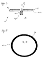
- FIG. 1 illustrates the basic principle of the optical mode of action of the insect trap 10.
- a trap surface 18 which consists of a bright surface 12 and disposed within the bright surface 12 contrast point 16.
- the contrast point 16 is significantly darker than the bright surface 12, in particular black.
- the entire surface 18 or parts thereof can simultaneously function as outflow surface 14, which emits a weak air flow 22 (cf. FIGS. 3, 5, 7 and 9).
- What is shown in the following figures as a round trap surface 18 can also have any other conceivable contour.
- the trap surface 18 also does not have to be flat, but can also be curved inwards or outwards.
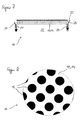
- Figure 2 illustrates a simple first variant of the insect trap 10 in a schematic cross section, but not according to the invention.
- Recognizable here is the uniformly bright surface 12 on the trap surface 18 and the approximately centrally arranged contrast point 16.
- the dark contrast 16 may in this case preferably be treated with glue or an insecticide so that the approaching insects are trapped and / or killed.
- FIG. 3 illustrates in a further schematic cross section a second variant of an insect trap 10, in which the bright surface 12 is designed as an outflow surface 14.
- the bright surface 12 is designed as an outflow surface 14.
- a uniform, weak air flow 22 which preferably has a flow velocity of less than 100 cm / s.
- the flow velocity of the weak air flow 22 may be about 5 to 20 cm / s and is thus capable of heat convection flow of a human or animal skin imitate that it is considered attractive to insects.
- the weak air flow 22 can emerge, in particular, through an outflow surface 14 formed as a tissue.
- the contrasting point 16 in the center of the outflow surface 14 configured as a light surface 12 may also be designed as an outflow surface.
- this second variant makes use of the mechanical attraction of the weak air flow, which is considered attractive for many insects, since it is modeled on the heat convection flow of a skin surface.
- Experiments have shown the surprising effect that blood-sucking insects are attracted to such air flow and apparently hold it for a heat convection flow of a body.
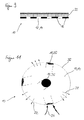
- FIG. 4 shows a variant of the insect trap 10 in a schematic cross section, but not according to the invention.
- This variant provides for a weak air flow 22 outside the bright area 12.
- the contrast point 16 is designed as a suction port 24, in the illustrated embodiment as an intake passage 26 through which a suction flow 25 is generated in a cavity 20 of the insect trap 10.
- the weak air flow 22 can serve in this variant of the insect trap 10 optionally as a means of transport for an attractant, which is attractive to the insects to be attracted.
- the attractant may mimic exudates of a human or animal body and consist of several components that are combined to form a fragrance mixture when released to the air flow 22.
- the intake flow 25 is at least so strong that insects entering a vicinity of the trap are drawn into the intake passage 26 and can no longer leave it.
- this acts as a contrast point 16, so that this trap variant combines an optical stimulus with a mechanical (air flow) and / or an olfactory stimulus (attractant).
- FIG. 5 shows a schematic cross section of a further variant of the insect trap 10 according to the invention, in which the bright surface 12 is designed as an outflow surface 14, through which the weak air flow 22 passes.
- the contrast point 16 is in turn formed as a dark-lined suction port 24 or channel 26 through which a stronger suction flow 25 at a flow rate of more than 1 m / s, preferably of up to 2 m / s or more passes.
- the weak air flow 22 can also transport an attractant here.
- FIGS. 6 and 7 show an alternative variant of an insect trap 10, in which the trap surface 18 is designed as a light surface 12 with an intake opening 24 arranged annularly around it.
- the suction opening 24 serves to generate a suction flow 25 into the cavity 20 of the insect trap 10.
- the bright surface 12 is formed as an outflow surface 14, through which a weak air flow 22 passes.
- the airflow 22 may optionally transport an attractant as previously described.
- FIGS. 8 and 9 show a further alternative variant, in which a plurality of dark contrasting points 16 are arranged on a light surface 12.
- a plurality of dark contrasting points 16 are arranged on a light surface 12.
- the bright surface 12 or the entire trap surface 18 may be formed as an outflow surface 14, through which the weak air flow 22 passes to the outside.
- the weak air flow can serve as a means of transport for an attractant.
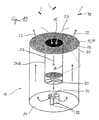
- the insect trap 10 comprises a cavity 20 within a hollow cylindrical body whose end face 32 is formed as a trap surface 18.
- the trap surface 18 comprises a bright surface 12, which is designed as an outflow surface 14 and has a center point 16 arranged in it contrast point, which is formed in the illustrated embodiment as an intake passage 26 with dark-lined inner circumferential surface 28.
- the bright surface 12 may in particular be formed by a fabric 15, which is stretched on the hollow cylindrical trap and through which the weak air flow 22 passes to the outside.
- a blower or a fan 30 is provided which generates the intake flow 25 into the cavity 20 of the insect trap 10.
- a plurality of attractant containers 38 can be seen, through each of which a component of an attractant 40 is delivered evenly and in a desired concentration, so that the attractant 40 delivered in a desired, optimal mixing ratio to the outside and into the weak air flow 22 becomes.
- the bright surface 12 and the diameter of the intake duct 26 are preferably matched to one another such that the single fan 30 ensures both the desired intake flow of approximately 2 m / s and the desired low air flow of approximately 5 to 20 cm / s can.
- a tissue is also mounted in front of the fan 30, which prevents the insects from entering the interior of the trap.
- a particularly advantageous embodiment may consist in that the intake duct 26 is provided with an insert which can be removed and emptied as soon as enough insects are trapped therein.
- the intake air flow 25 is to be designed at least so strong that in the vicinity of the trap 10 located insects 42 are sucked into the intake passage 26 and can not leave this.
- FIG. 11 shows a schematic representation of an alternative embodiment of the insect trap 10, which is formed in this case as a spherical body.
- the spherical surface 36 of the insect trap 10 may optionally be formed as an outflow surface 14.
- a plurality of intake passages 26 are arranged distributed over the spherical surface, so that at least one dark contrast point 16 on the bright spherical surface can be seen from any perspective.
- the spherical insect trap 10 according to FIG. 11 can have a greater effectiveness owing to its substantially larger effective surface than the cylindrical variant of FIG. 10, since the optical component acts in all directions with the dark contrasting points 16 of the suction channels 26.
- this can optionally additionally serve as a transport medium for an attractant 40.
- the weak air flow 22 simulates a heat convection flow of a human or animal body.
- the attractant 40 can in particular emulate human or animal exhalations. Alternatively, however, other attractants may be used which are attractive to the insects to be attracted.
- the contrasting point 16 arranged inside the bright area 12 is preferably sufficiently dark that it is recognized as an optical stimulus signal by the insects 42 to be attracted.
- FIG. 12 shows a freely suspended trap 10, but not according to the invention, with a cover 44 arranged above it and spaced therefrom.
- the trap 10 can have any shape, for example a hollow cylindrical or spherical one according to FIGS. 10 or 11.
- the cover 44 may optionally be transparent to expose the bright surface 12 of the trap 10 with the dark contrast 14 located therein for the insects.
- the cover 44 itself may be formed as a light surface with a dark contrasting point disposed therein to attract the insects from further distance.
- the insect trap according to the invention is particularly suitable for mosquitoes, mosquitoes and other stinging and / or blood sucking insect species.
Landscapes
- Life Sciences & Earth Sciences (AREA)
- Pest Control & Pesticides (AREA)
- Engineering & Computer Science (AREA)
- Insects & Arthropods (AREA)
- Wood Science & Technology (AREA)
- Zoology (AREA)
- Environmental Sciences (AREA)
- Health & Medical Sciences (AREA)
- General Health & Medical Sciences (AREA)
- Toxicology (AREA)
- Catching Or Destruction (AREA)
- Agricultural Chemicals And Associated Chemicals (AREA)
Claims (10)
- Piège à insectes, notamment pour insectes volant et/ou nuisibles, comprenant une surface claire plane ou courbe (12) et une surface d'écoulement (14) destinée à produire un courant d'air faible (22) sortant de la surface (14), et comprenant des dispositifs servant à retenir, capturer et/ou tuer des insectes attirés (42) sur une surface (18) du piège à insectes (10) et/ou dans un espace creux (20) disposé dans celui-ci, caractérisé en ce que la surface d'écoulement (14) est réalisée sous forme de surface claire (12) avec au moins un point de contraste sombre (16) disposé à l'intérieur de celle-ci.
- Piège à insectes selon la revendication 1, caractérisé par une substance d'appât (40) pouvant être émise par le piège (10) et attirante pour les insectes que l'on cherche à attirer (42).
- Piège à insectes selon la revendication 1 ou 2, caractérisé en ce que le point de contraste sombre (16) est réalisé sous la forme d'un canal d'aspiration sombre (26).
- Piège à insectes selon au moins l'une quelconque des revendications précédentes, caractérisé par au moins une soufflante (30) disposée dans le piège pour produire un courant d'aspiration (25) dans le canal d'aspiration (26) ou dans l'au moins une ouverture d'aspiration (24) et/ou le faible courant d'air (22) sortant de la surface d'écoulement (14).
- Piège à insectes selon au moins l'une quelconque des revendications précédentes, caractérisé par un dispositif disposé à l'intérieur du piège (10) pour diffuser uniformément la substance d'appât (40) au niveau du faible écoulement d'air (22).
- Piège à insectes selon au moins l'une quelconque des revendications précédentes, caractérisé en ce que le piège (10) présente une forme cylindrique creuse avec une surface d'écoulement (14) disposée du côté frontal et un canal d'aspiration sombre (26) disposé dans celle-ci.
- Piège à insectes selon la revendication 6, caractérisé par une surface frontale (32) du piège cylindrique creux (10) tournée vers le haut.
- Piège à insectes selon la revendication 6 ou 7, caractérisé par une surface de fond fermée (34) avec un dispositif disposé dessus pour diffuser la substance d'appât (40).
- Piège à insectes selon au moins l'une quelconque des revendications 1 à 5, caractérisé en ce que le piège (10) présente une forme sphérique avec plusieurs canaux d'aspiration (26) répartis sur sa surface.
- Piège à insectes selon la revendication 9, caractérisé en ce que certaines parties au moins de la surface sphérique (36) sont réalisées sous forme de surfaces d'écoulement (14).
Applications Claiming Priority (5)
| Application Number | Priority Date | Filing Date | Title |
|---|---|---|---|
| DE10259651A DE10259651A1 (de) | 2002-12-18 | 2002-12-18 | Insektenfalle |
| DE10259651 | 2002-12-18 | ||
| US43456302P | 2002-12-19 | 2002-12-19 | |
| US434563P | 2002-12-19 | ||
| PCT/DE2003/004162 WO2004054358A2 (fr) | 2002-12-18 | 2003-12-17 | Piege a insectes |
Publications (2)
| Publication Number | Publication Date |
|---|---|
| EP1575355A2 EP1575355A2 (fr) | 2005-09-21 |
| EP1575355B1 true EP1575355B1 (fr) | 2006-08-02 |
Family
ID=32598085
Family Applications (1)
| Application Number | Title | Priority Date | Filing Date |
|---|---|---|---|
| EP03795753A Expired - Lifetime EP1575355B1 (fr) | 2002-12-18 | 2003-12-17 | Piege a insectes |
Country Status (8)
| Country | Link |
|---|---|
| EP (1) | EP1575355B1 (fr) |
| AT (1) | ATE334585T1 (fr) |
| AU (1) | AU2003303020B2 (fr) |
| BR (1) | BR0317242A (fr) |
| DE (1) | DE50304521D1 (fr) |
| ES (1) | ES2273079T3 (fr) |
| MX (1) | MXPA05006570A (fr) |
| WO (1) | WO2004054358A2 (fr) |
Cited By (4)
| Publication number | Priority date | Publication date | Assignee | Title |
|---|---|---|---|---|
| DE102015110500A1 (de) | 2015-06-30 | 2017-01-05 | Biogents Ag | Insektenfalle |
| DE102015110499A1 (de) | 2015-06-30 | 2017-01-05 | Biogents Ag | Insektenfalle und Verfahren zum Umpositionieren einer Insektenfalle |
| WO2019042839A1 (fr) | 2017-09-01 | 2019-03-07 | Biogents Ag | Pièce à insectes et procédé permettant d'attirer et/ou de capturer des insectes volant |
| EP4062758A1 (fr) * | 2021-03-24 | 2022-09-28 | Premal B.V. | Piège à insectes |
Families Citing this family (8)
| Publication number | Priority date | Publication date | Assignee | Title |
|---|---|---|---|---|
| US7073287B2 (en) * | 2004-09-13 | 2006-07-11 | Leung Fai Lau | Mosquitoes eradicating system |
| CN101820750A (zh) * | 2007-05-24 | 2010-09-01 | 弗莱摩利系统朔伊贝克兄弟股份有限公司 | 用于捕捉昆虫的设备 |
| US20120317868A1 (en) * | 2011-06-15 | 2012-12-20 | Ecolab Usa Inc. | Flying insect attraction station |
| US10292379B2 (en) * | 2011-06-15 | 2019-05-21 | Ecolab Usa Inc. | Flying insect attraction station |
| EP3657941B1 (fr) | 2017-07-28 | 2022-03-16 | Biogents Aktiengesellschaft | Procédé et système pour l'enregistrement et/ou la surveillance de populations d'insectes |
| CN108308141A (zh) * | 2018-03-11 | 2018-07-24 | 麻江县贤昌中心学校 | 一种蚊蝇捕捉器 |
| CN110024761B (zh) * | 2019-05-14 | 2024-02-27 | 浙江省农业科学院 | 昆虫诱捕器 |
| WO2023244959A1 (fr) * | 2022-06-13 | 2023-12-21 | Ecolab Usa Inc. | Système pour insectes volants |
Family Cites Families (7)
| Publication number | Priority date | Publication date | Assignee | Title |
|---|---|---|---|---|
| US1478424A (en) * | 1921-12-16 | 1923-12-25 | Clifford W Worden | Insect exterminator |
| FR693878A (fr) * | 1930-04-14 | 1930-11-26 | Dispositif pour capturer des insectes, en particulier pendant la nuit | |
| GB424235A (en) * | 1934-02-12 | 1935-02-18 | Paul Boutellier | Improvements in traps for insects |
| GB9020059D0 (en) * | 1990-09-13 | 1990-10-24 | Quartey George K | Device for attracting moths |
| US5365690B1 (en) * | 1993-01-04 | 1998-03-03 | Ecolab Inc | Flying insect trap using reflected and radiated light |
| SE9502308L (sv) * | 1995-06-27 | 1996-12-28 | Silvandersson Miljoe Ab | Anordning vid insektsfångare |
| US6286249B1 (en) | 1996-09-17 | 2001-09-11 | American Biophysics Corp. | Counterflow insect trap |
-
2003
- 2003-12-17 AU AU2003303020A patent/AU2003303020B2/en not_active Ceased
- 2003-12-17 BR BR0317242-2A patent/BR0317242A/pt not_active Application Discontinuation
- 2003-12-17 EP EP03795753A patent/EP1575355B1/fr not_active Expired - Lifetime
- 2003-12-17 DE DE50304521T patent/DE50304521D1/de not_active Expired - Lifetime
- 2003-12-17 MX MXPA05006570A patent/MXPA05006570A/es active IP Right Grant
- 2003-12-17 ES ES03795753T patent/ES2273079T3/es not_active Expired - Lifetime
- 2003-12-17 WO PCT/DE2003/004162 patent/WO2004054358A2/fr not_active Application Discontinuation
- 2003-12-17 AT AT03795753T patent/ATE334585T1/de not_active IP Right Cessation
Cited By (7)
| Publication number | Priority date | Publication date | Assignee | Title |
|---|---|---|---|---|
| DE102015110500A1 (de) | 2015-06-30 | 2017-01-05 | Biogents Ag | Insektenfalle |
| DE102015110499A1 (de) | 2015-06-30 | 2017-01-05 | Biogents Ag | Insektenfalle und Verfahren zum Umpositionieren einer Insektenfalle |
| WO2019042839A1 (fr) | 2017-09-01 | 2019-03-07 | Biogents Ag | Pièce à insectes et procédé permettant d'attirer et/ou de capturer des insectes volant |
| DE102017120212A1 (de) | 2017-09-01 | 2019-03-07 | Biogents Ag | Insektenfalle und Verfahren zum Anlocken und/oder Fangen von Fluginsekten |
| US11758895B2 (en) | 2017-09-01 | 2023-09-19 | Biogents Ag | Insect trap and method for attracting and/or capturing flying insects |
| EP4062758A1 (fr) * | 2021-03-24 | 2022-09-28 | Premal B.V. | Piège à insectes |
| WO2022200179A1 (fr) * | 2021-03-24 | 2022-09-29 | Premal B.V. | Piège à insectes |
Also Published As
| Publication number | Publication date |
|---|---|
| AU2003303020B2 (en) | 2010-03-11 |
| AU2003303020A1 (en) | 2004-07-09 |
| ATE334585T1 (de) | 2006-08-15 |
| DE50304521D1 (de) | 2006-09-14 |
| BR0317242A (pt) | 2005-11-01 |
| EP1575355A2 (fr) | 2005-09-21 |
| WO2004054358A2 (fr) | 2004-07-01 |
| WO2004054358A3 (fr) | 2004-12-16 |
| ES2273079T3 (es) | 2007-05-01 |
| MXPA05006570A (es) | 2006-05-25 |
Similar Documents
| Publication | Publication Date | Title |
|---|---|---|
| DE10259651A1 (de) | Insektenfalle | |
| DE69932354T2 (de) | Verfahren und vorrichtung zum dispersieren einer flüchtigen zusammensetzung | |
| EP1575355B1 (fr) | Piege a insectes | |
| DE60202879T2 (de) | Insektenbekämpfungsvorrichtung | |
| WO2007017174A1 (fr) | Dispositif pour attirer des insectes | |
| DE202008000690U1 (de) | Fluginsektenfalle | |
| EP1745697A1 (fr) | Dispositif pour attirer les insectes, et système pour attirer et capturer les insectes | |
| EP3675628B1 (fr) | Pièce à insectes et procédé permettant d'attirer et/ou de capturer des insectes volant | |
| DE60116837T2 (de) | Insektenfalle und Garnitur | |
| EP0019168B1 (fr) | Utilisation d'un dispositif pour attirer des insectes utiles | |
| KR20020017584A (ko) | 해충포집장치 | |
| DE3810065C1 (en) | Device for catching insects | |
| DE60211700T2 (de) | Semiochemikalie und schallsignale zum überwachen und bekämpfen der kleidermotte | |
| CA2511015C (fr) | Piege a insectes | |
| DE102008008241B4 (de) | Mückenlarvenfalle | |
| DE19515454A1 (de) | Vorrichtung zum Bekämpfen von fliegenden Forstschädlingen | |
| DE102015110500A1 (de) | Insektenfalle | |
| DE3316045A1 (de) | Mueckenfaenger | |
| EP2399456A1 (fr) | Dispositif et procédé de lutte contre les insectes | |
| DE102006039990A1 (de) | Bodenmatte mit umlaufendem Insektenschutz | |
| KR20180014139A (ko) | 곤충 포집장치 | |
| DE202023000706U1 (de) | System zum Überwachen von vorgebbaren Arten von Lebewesen oder von bestimmten Lebewesen und deren Umgebungsbedingungen an einem vorgebbaren Standort | |
| DE2501917C3 (de) | Mit einer Lampe ausgestattete Fliegenfalle aus einem Auffang-Grundkörper und einer Loch-Haube | |
| DE885497C (de) | Geraet zum Fangen oder Anlocken von Kleintieren, insbesondere von Fliegen und anderen landwirtschaftlich schaedlichen Insekten | |
| KR200214127Y1 (ko) | 해충포집장치 |
Legal Events
| Date | Code | Title | Description |
|---|---|---|---|
| PUAI | Public reference made under article 153(3) epc to a published international application that has entered the european phase |
Free format text: ORIGINAL CODE: 0009012 |
|
| 17P | Request for examination filed |
Effective date: 20050716 |
|
| AK | Designated contracting states |
Kind code of ref document: A2 Designated state(s): AT BE BG CH CY CZ DE DK EE ES FI FR GB GR HU IE IT LI LU MC NL PT RO SE SI SK TR |
|
| GRAP | Despatch of communication of intention to grant a patent |
Free format text: ORIGINAL CODE: EPIDOSNIGR1 |
|
| RIC1 | Information provided on ipc code assigned before grant |
Ipc: A01M 1/02 20060101AFI20051229BHEP Ipc: A01M 1/14 20060101ALI20051229BHEP Ipc: A01M 1/08 20060101ALI20051229BHEP |
|
| GRAS | Grant fee paid |
Free format text: ORIGINAL CODE: EPIDOSNIGR3 |
|
| GRAA | (expected) grant |
Free format text: ORIGINAL CODE: 0009210 |
|
| AK | Designated contracting states |
Kind code of ref document: B1 Designated state(s): AT BE BG CH CY CZ DE DK EE ES FI FR GB GR HU IE IT LI LU MC NL PT RO SE SI SK TR |
|
| PG25 | Lapsed in a contracting state [announced via postgrant information from national office to epo] |
Ref country code: RO Free format text: LAPSE BECAUSE OF FAILURE TO SUBMIT A TRANSLATION OF THE DESCRIPTION OR TO PAY THE FEE WITHIN THE PRESCRIBED TIME-LIMIT Effective date: 20060802 Ref country code: NL Free format text: LAPSE BECAUSE OF FAILURE TO SUBMIT A TRANSLATION OF THE DESCRIPTION OR TO PAY THE FEE WITHIN THE PRESCRIBED TIME-LIMIT Effective date: 20060802 Ref country code: IE Free format text: LAPSE BECAUSE OF FAILURE TO SUBMIT A TRANSLATION OF THE DESCRIPTION OR TO PAY THE FEE WITHIN THE PRESCRIBED TIME-LIMIT Effective date: 20060802 Ref country code: CZ Free format text: LAPSE BECAUSE OF FAILURE TO SUBMIT A TRANSLATION OF THE DESCRIPTION OR TO PAY THE FEE WITHIN THE PRESCRIBED TIME-LIMIT Effective date: 20060802 Ref country code: FI Free format text: LAPSE BECAUSE OF FAILURE TO SUBMIT A TRANSLATION OF THE DESCRIPTION OR TO PAY THE FEE WITHIN THE PRESCRIBED TIME-LIMIT Effective date: 20060802 Ref country code: SK Free format text: LAPSE BECAUSE OF FAILURE TO SUBMIT A TRANSLATION OF THE DESCRIPTION OR TO PAY THE FEE WITHIN THE PRESCRIBED TIME-LIMIT Effective date: 20060802 Ref country code: SI Free format text: LAPSE BECAUSE OF FAILURE TO SUBMIT A TRANSLATION OF THE DESCRIPTION OR TO PAY THE FEE WITHIN THE PRESCRIBED TIME-LIMIT Effective date: 20060802 |
|
| REG | Reference to a national code |
Ref country code: GB Ref legal event code: FG4D Free format text: NOT ENGLISH |
|
| REG | Reference to a national code |
Ref country code: CH Ref legal event code: EP |
|
| REG | Reference to a national code |
Ref country code: IE Ref legal event code: FG4D Free format text: LANGUAGE OF EP DOCUMENT: GERMAN |
|
| REF | Corresponds to: |
Ref document number: 50304521 Country of ref document: DE Date of ref document: 20060914 Kind code of ref document: P |
|
| PG25 | Lapsed in a contracting state [announced via postgrant information from national office to epo] |
Ref country code: BG Free format text: LAPSE BECAUSE OF FAILURE TO SUBMIT A TRANSLATION OF THE DESCRIPTION OR TO PAY THE FEE WITHIN THE PRESCRIBED TIME-LIMIT Effective date: 20061102 Ref country code: DK Free format text: LAPSE BECAUSE OF FAILURE TO SUBMIT A TRANSLATION OF THE DESCRIPTION OR TO PAY THE FEE WITHIN THE PRESCRIBED TIME-LIMIT Effective date: 20061102 |
|
| REG | Reference to a national code |
Ref country code: SE Ref legal event code: TRGR |
|
| GBT | Gb: translation of ep patent filed (gb section 77(6)(a)/1977) |
Effective date: 20061113 |
|
| REG | Reference to a national code |
Ref country code: HU Ref legal event code: AG4A Ref document number: E000847 Country of ref document: HU |
|
| PG25 | Lapsed in a contracting state [announced via postgrant information from national office to epo] |
Ref country code: MC Free format text: LAPSE BECAUSE OF NON-PAYMENT OF DUE FEES Effective date: 20061231 Ref country code: BE Free format text: LAPSE BECAUSE OF NON-PAYMENT OF DUE FEES Effective date: 20061231 |
|
| NLV1 | Nl: lapsed or annulled due to failure to fulfill the requirements of art. 29p and 29m of the patents act | ||
| PG25 | Lapsed in a contracting state [announced via postgrant information from national office to epo] |
Ref country code: PT Free format text: LAPSE BECAUSE OF FAILURE TO SUBMIT A TRANSLATION OF THE DESCRIPTION OR TO PAY THE FEE WITHIN THE PRESCRIBED TIME-LIMIT Effective date: 20070102 |
|
| ET | Fr: translation filed | ||
| REG | Reference to a national code |
Ref country code: IE Ref legal event code: FD4D |
|
| REG | Reference to a national code |
Ref country code: ES Ref legal event code: FG2A Ref document number: 2273079 Country of ref document: ES Kind code of ref document: T3 |
|
| PLBE | No opposition filed within time limit |
Free format text: ORIGINAL CODE: 0009261 |
|
| STAA | Information on the status of an ep patent application or granted ep patent |
Free format text: STATUS: NO OPPOSITION FILED WITHIN TIME LIMIT |
|
| PG25 | Lapsed in a contracting state [announced via postgrant information from national office to epo] |
Ref country code: DE Free format text: LAPSE BECAUSE OF NON-PAYMENT OF DUE FEES Effective date: 20070703 |
|
| 26N | No opposition filed |
Effective date: 20070503 |
|
| REG | Reference to a national code |
Ref country code: FR Ref legal event code: ST Effective date: 20070831 |
|
| BERE | Be: lapsed |
Owner name: UNIVERSITAT REGENSBURG Effective date: 20061231 |
|
| PGRI | Patent reinstated in contracting state [announced from national office to epo] |
Ref country code: DE Effective date: 20071112 |
|
| REG | Reference to a national code |
Ref country code: FR Ref legal event code: RN |
|
| PG25 | Lapsed in a contracting state [announced via postgrant information from national office to epo] |
Ref country code: AT Free format text: LAPSE BECAUSE OF NON-PAYMENT OF DUE FEES Effective date: 20061217 |
|
| REG | Reference to a national code |
Ref country code: FR Ref legal event code: FC |
|
| PG25 | Lapsed in a contracting state [announced via postgrant information from national office to epo] |
Ref country code: FR Free format text: LAPSE BECAUSE OF NON-PAYMENT OF DUE FEES Effective date: 20070102 Ref country code: GR Free format text: LAPSE BECAUSE OF FAILURE TO SUBMIT A TRANSLATION OF THE DESCRIPTION OR TO PAY THE FEE WITHIN THE PRESCRIBED TIME-LIMIT Effective date: 20061103 |
|
| PG25 | Lapsed in a contracting state [announced via postgrant information from national office to epo] |
Ref country code: EE Free format text: LAPSE BECAUSE OF FAILURE TO SUBMIT A TRANSLATION OF THE DESCRIPTION OR TO PAY THE FEE WITHIN THE PRESCRIBED TIME-LIMIT Effective date: 20060802 |
|
| PG25 | Lapsed in a contracting state [announced via postgrant information from national office to epo] |
Ref country code: TR Free format text: LAPSE BECAUSE OF FAILURE TO SUBMIT A TRANSLATION OF THE DESCRIPTION OR TO PAY THE FEE WITHIN THE PRESCRIBED TIME-LIMIT Effective date: 20060802 Ref country code: LU Free format text: LAPSE BECAUSE OF NON-PAYMENT OF DUE FEES Effective date: 20061217 |
|
| PGRI | Patent reinstated in contracting state [announced from national office to epo] |
Ref country code: FR Effective date: 20080130 |
|
| PG25 | Lapsed in a contracting state [announced via postgrant information from national office to epo] |
Ref country code: CY Free format text: LAPSE BECAUSE OF FAILURE TO SUBMIT A TRANSLATION OF THE DESCRIPTION OR TO PAY THE FEE WITHIN THE PRESCRIBED TIME-LIMIT Effective date: 20060802 |
|
| REG | Reference to a national code |
Ref country code: FR Ref legal event code: PLFP Year of fee payment: 13 |
|
| REG | Reference to a national code |
Ref country code: FR Ref legal event code: PLFP Year of fee payment: 14 |
|
| REG | Reference to a national code |
Ref country code: FR Ref legal event code: PLFP Year of fee payment: 15 |
|
| PGFP | Annual fee paid to national office [announced via postgrant information from national office to epo] |
Ref country code: NO Payment date: 20181203 Year of fee payment: 10 |
|
| PGFP | Annual fee paid to national office [announced via postgrant information from national office to epo] |
Ref country code: GB Payment date: 20181218 Year of fee payment: 16 |
|
| GBPC | Gb: european patent ceased through non-payment of renewal fee |
Effective date: 20191217 |
|
| PG25 | Lapsed in a contracting state [announced via postgrant information from national office to epo] |
Ref country code: GB Free format text: LAPSE BECAUSE OF NON-PAYMENT OF DUE FEES Effective date: 20191217 |
|
| PG25 | Lapsed in a contracting state [announced via postgrant information from national office to epo] |
Ref country code: HU Free format text: LAPSE BECAUSE OF NON-PAYMENT OF DUE FEES Effective date: 20191218 |
|
| PGFP | Annual fee paid to national office [announced via postgrant information from national office to epo] |
Ref country code: SE Payment date: 20221222 Year of fee payment: 20 Ref country code: FR Payment date: 20221222 Year of fee payment: 20 Ref country code: DE Payment date: 20221213 Year of fee payment: 20 |
|
| PGFP | Annual fee paid to national office [announced via postgrant information from national office to epo] |
Ref country code: ES Payment date: 20230224 Year of fee payment: 20 Ref country code: CH Payment date: 20230103 Year of fee payment: 20 |
|
| PGFP | Annual fee paid to national office [announced via postgrant information from national office to epo] |
Ref country code: IT Payment date: 20221228 Year of fee payment: 20 |
|
| REG | Reference to a national code |
Ref country code: DE Ref legal event code: R071 Ref document number: 50304521 Country of ref document: DE |
|
| REG | Reference to a national code |
Ref country code: CH Ref legal event code: PL Ref country code: ES Ref legal event code: FD2A Effective date: 20231229 |
|
| PG25 | Lapsed in a contracting state [announced via postgrant information from national office to epo] |
Ref country code: ES Free format text: LAPSE BECAUSE OF EXPIRATION OF PROTECTION Effective date: 20231218 |
|
| REG | Reference to a national code |
Ref country code: SE Ref legal event code: EUG |
|
| PG25 | Lapsed in a contracting state [announced via postgrant information from national office to epo] |
Ref country code: ES Free format text: LAPSE BECAUSE OF EXPIRATION OF PROTECTION Effective date: 20231218 |