EP1575355B1 - Insektenfalle - Google Patents
Insektenfalle Download PDFInfo
- Publication number
- EP1575355B1 EP1575355B1 EP03795753A EP03795753A EP1575355B1 EP 1575355 B1 EP1575355 B1 EP 1575355B1 EP 03795753 A EP03795753 A EP 03795753A EP 03795753 A EP03795753 A EP 03795753A EP 1575355 B1 EP1575355 B1 EP 1575355B1
- Authority
- EP
- European Patent Office
- Prior art keywords
- trap
- insect trap
- insects
- insect
- dark
- Prior art date
- Legal status (The legal status is an assumption and is not a legal conclusion. Google has not performed a legal analysis and makes no representation as to the accuracy of the status listed.)
- Expired - Lifetime
Links
Images


Classifications
-
- A—HUMAN NECESSITIES
- A01—AGRICULTURE; FORESTRY; ANIMAL HUSBANDRY; HUNTING; TRAPPING; FISHING
- A01M—CATCHING, TRAPPING OR SCARING OF ANIMALS; APPARATUS FOR THE DESTRUCTION OF NOXIOUS ANIMALS OR NOXIOUS PLANTS
- A01M1/00—Stationary means for catching or killing insects
- A01M1/20—Poisoning, narcotising, or burning insects
- A01M1/2005—Poisoning insects using bait stations
- A01M1/2016—Poisoning insects using bait stations for flying insects
-
- A—HUMAN NECESSITIES
- A01—AGRICULTURE; FORESTRY; ANIMAL HUSBANDRY; HUNTING; TRAPPING; FISHING
- A01M—CATCHING, TRAPPING OR SCARING OF ANIMALS; APPARATUS FOR THE DESTRUCTION OF NOXIOUS ANIMALS OR NOXIOUS PLANTS
- A01M1/00—Stationary means for catching or killing insects
- A01M1/02—Stationary means for catching or killing insects with devices or substances, e.g. food, pheronones attracting the insects
- A01M1/026—Stationary means for catching or killing insects with devices or substances, e.g. food, pheronones attracting the insects combined with devices for monitoring insect presence, e.g. termites
-
- A—HUMAN NECESSITIES
- A01—AGRICULTURE; FORESTRY; ANIMAL HUSBANDRY; HUNTING; TRAPPING; FISHING
- A01M—CATCHING, TRAPPING OR SCARING OF ANIMALS; APPARATUS FOR THE DESTRUCTION OF NOXIOUS ANIMALS OR NOXIOUS PLANTS
- A01M1/00—Stationary means for catching or killing insects
- A01M1/08—Attracting and catching insects by using combined illumination or colours and suction effects
-
- A—HUMAN NECESSITIES
- A01—AGRICULTURE; FORESTRY; ANIMAL HUSBANDRY; HUNTING; TRAPPING; FISHING
- A01M—CATCHING, TRAPPING OR SCARING OF ANIMALS; APPARATUS FOR THE DESTRUCTION OF NOXIOUS ANIMALS OR NOXIOUS PLANTS
- A01M1/00—Stationary means for catching or killing insects
- A01M1/14—Catching by adhesive surfaces
- A01M1/145—Attracting and catching insects using combined illumination or colours and adhesive surfaces
-
- A—HUMAN NECESSITIES
- A01—AGRICULTURE; FORESTRY; ANIMAL HUSBANDRY; HUNTING; TRAPPING; FISHING
- A01M—CATCHING, TRAPPING OR SCARING OF ANIMALS; APPARATUS FOR THE DESTRUCTION OF NOXIOUS ANIMALS OR NOXIOUS PLANTS
- A01M2200/00—Kind of animal
- A01M2200/01—Insects
- A01M2200/012—Flying insects
Definitions
- the invention relates to an insect trap, in particular for aviation and / or pest insects having the features of the preamble of independent claim 1, see, for example, document CA-A-1 227 929.
- Blood-sucking insects are among the most important sanitary pests in the world, as they transmit numerous diseases to humans (eg malaria, yellow fever, dengue, etc.) and animals and can also be extremely annoying.
- humans eg malaria, yellow fever, dengue, etc.
- insects can also be extremely annoying.
- One way of controlling these pests over a large area is the use of insecticides.
- Another possibility for controlling and controlling noxious insects is the use of trap systems, which, however, are mainly suitable only for smaller areas, especially for closed spaces.
- Insect traps are known in many embodiments and variants. Simple variants exist for example in glue rods, which are provided with attractants and on which the insects are held after contact. Other variants emit ultraviolet light or ultrasound, thus trying to attract insect pests. Devices are also known which emit odorants and attractants, for example with the aid of an air flow, according to which the insects attracted thereby are sucked into a cavity with the aid of an opposing air flow and held captive there.
- An object of the present invention is to provide an insect trap which is simple in construction, cost effective and most effective.
- a first aspect of an insect trap according to the invention which serves in particular for attracting avian and / or pest insects, has a flat or curved, light surface and at least one dark contrast point arranged within this surface.
- the insect trap further comprises means for holding, catching and / or killing attracted insects on a surface of the trap and / or in a trap disposed therein Cavity on.
- dark objects for many insects has a signal effect and attracts them.
- a bright surface with a dark spot arranged therein, for example in its center is very attractive to certain insects and attracts them. So far, it was only known that dark objects may be able to attract certain species of insects.
- the invention makes use of the better signal effect of a dark contrasting point on a light surface.
- a second aspect of the insect trap includes an outflow surface for generating or discharging a weak airflow emanating from the surface and means for holding, capturing and / or killing attracted insects on a surface of the trap and / or in a cavity disposed therein.
- a large-scale, weak and evenly distributed air flow is also attractive for many insect pests and can attract them. This can be explained by the fact that the large-scale, weak air flow is similar to a heat given off by a human or animal body, which is recognized by many insects, especially mosquitoes (aedes aegypti) and blood-sucking insects and is considered attractive.
- a bright surface with a dark contrasting point is provided with an outflow surface at the same time or is designed as such. This can improve the effectiveness of the trap.
- An embodiment of the insect trap according to the invention provides that at least the light surface is provided with glue and / or an insecticide.
- the dark contrasting site can also be provided with glue and / or an insecticide, so that the surface of the trap can act as an adhesive for the attracted insects.
- the insects can be killed upon contact with a trap surface. This can also be achieved by applying a voltage to a surface of the insect trap, for example by means of a wire mesh under tension or the like.
- the weak air flow emitted by the outflow surface preferably has an average flow velocity of between 2 and 100 cm / s, more preferably between 3 and 50 cm / s, but preferably between 5 and 20 cm / s, so that the weak air flow is particularly well that of can convict a convection flow of the air generated by a human or animal body.
- a particularly preferred embodiment of the insect trap provides that an attractant is additionally emitted by the trap.
- an attractant is additionally emitted by the trap.
- the knowledge is taken advantage of that the smell of a human or animal body for insects is particularly attractive when it is transported in a weak, evenly distributed air flow.
- an attractant mimicking the skin odor is particularly attractive to the insects when it is transported in a weak air or convection flow, as provided by the present invention.
- the attractant may be emitted from parts or the entire bright surface.
- the attractant may, for example, in a coating of light surface bound and delivered in a definable concentration.
- a binder on the light and / or dark surface in which the volatile attractants are dissolved and released in definable concentration is suitable.
- such a binder may be glue to which sticking insects adhere. So that the attractant is dispensed uniformly and transported in a convection flow, a heating of the trap surface may be provided, for example by means of heating wires or the like.
- a combination of the olfactory and the visual stimuli for the insects wherein the outflow surface is designed as a bright surface with at least one dark contrast point arranged within it.
- the bright area has a size of typically at least 30 cm 2 , but should preferably have a size of at least 100 cm 2 in order to exert the desired effect even at a greater distance.
- Such a combined, optical and olfactory effect of the insect trap according to the invention mimics particularly well human and animal body, so that such a trap has a high attractiveness and thus a high efficiency for many insects, especially for blood-sucking species.
- a further embodiment of the invention provides that at least one suction opening is provided for sucking attracted insects.
- a plurality of suction openings may be arranged around the bright surface or around the outflow surface.
- an annular suction opening can also be formed around the bright surface.
- the attracted insects can be sucked into a cavity or container in which they are collected and from which they no longer flee can.
- an insecticide may be incorporated in this cavity so that the insects are killed in situ.
- a preferred embodiment of the invention provides that the dark contrast point is formed as a dark intake channel. That is, an inner circumferential surface of the tubular intake passage is preferably darkly coated, so that the intake passage itself can act as a dark contrasting spot on the bright surface.
- a flow velocity at or in the intake duct or in the at least one intake opening is preferably more than 1 m / s and, in a preferred embodiment, may be approximately 2 m / s. In this way it can be ensured that insects that reach the vicinity of the intake duct or the intake, are reliably sucked in and can no longer flee. At the same time it is ensured that the insects can not approach the air flow and, for example, can leave the cavity after catching it.
- a further preferred embodiment of the invention provides at least one fan arranged in the trap for generating the intake flow and / or the weak air flow from the outflow surface.
- the fan can generate a ring flow, a suction being produced through the suction opening or through the intake channel and the air sucked in here being discharged again via the larger discharge surface as a uniform, weak air flow.
- the size ratios of the intake duct and the outflow surface must be coordinated in this case so that the desired air speeds are achieved.
- a device arranged within the trap for the uniform delivery of the attractant is provided.
- a device may in particular consist of several bottles with the individual components of the attractant or of different tubes with attractant components disposed therein, since the attractant is typically not stored as a mixture, but in individual components and is only on delivery to the air to a attractant mixture.
- an attractant is particularly a mixture of lactic acid, caproic acid and ammonia in question, as it is, for example, in the provisional US Application No. 60 / 386,582 from 07.06.2002 apparent.
- the active substance and attractant combinations and mixtures mentioned in this application are hereby expressly included in the disclosure of the present application.
- the outflow surface may have a covering with a light tissue whose mesh size is smaller than the size of the attracted insects.
- the bright surface can be formed and on the other hand, the trap can be closed to the outside, so that trapped insects can no longer fly through the tissue.
- the suction channel preferably has a minimum length which causes a sufficiently uniform flow in the channel and in the immediate vicinity of the channel.
- a typical length of the intake passage may be, for example, between 5 and 10 cm or more.
- a typical diameter of the intake duct may for example be between 3 and 15 cm.
- the dimensions of the outflow surface and of the intake channel depend in particular on the desired size of the trap and on the desired ratios of the flow velocities in the channel and out of the outflow direction. Also, the typical size of the preferred attracted insects affects the meaningful dimensions of the intake duct and the trap.
- An embodiment of the invention provides an additional fabric tension in front of the fan, so that the sucked insects do not get into the inside of the trap, but are collected at the bottom of the intake duct.
- An advantageous embodiment provides an insert module in front of the fan in the channel, which may optionally be provided with an adhesive or with an insecticide and which can be removed at regular intervals from the trap and emptied. To prevent the sucked insects from escaping again, it can be ensured, for example, that the fan blower runs permanently. If the fan does not run permanently, it may be advantageous to provide a trap-like catch container from which the insects can not escape. In such a variant, the fan can optionally run in an interval operation.
- a preferred form of the insect trap according to the invention provides a hollow cylindrical body with an outlet surface arranged on the front side and a dark intake channel leading into the interior of the hollow cylindrical body.
- the end face may optionally be curved outwards or inwards.
- a closed bottom surface with device arranged thereon for dispensing the attractant is preferably provided.
- the end face of the hollow cylindrical trap preferably faces upwards.
- the trap thus has the advantage of better recognizability for insects as compared to a trap emanating carbon dioxide, since these can better perceive the light surface or the effluent attractant than with a downwardly facing effective surface of the trap.
- Carbon dioxide traps usually pour it down, as the CO 2 is heavier than air and sinks down.
- An alternative embodiment of the invention provides a trap in spherical shape with one or more arranged distributed over the surface thereof Intake ducts before. At least parts of the spherical surface may be formed as outflow openings. Preferably, however, in such an insect trap, substantially the entire spherical surface is formed as an outflow opening.
- a further embodiment of the invention provides a cover above the trap and spaced from this, which serves as weather protection.
- the cover can prevent rain from impairing or rendering ineffective the trap.
- the cover may optionally be transparent so that the insects can perceive the bright area with the dark contrast spot.
- the cover itself may be configured as an optical lure. For this purpose, it can be configured in particular as a light surface with one or more dark contrasting points.
- the latch is preferably suspended freely, for example on a cord or chain, by means of which it may be suspended from a tree, a rack or other suitable location.
- the insect traps according to the invention are suitable not only for pest control indoors and outdoors, but also for detecting an insect density in a particular area.
- monitoring such traps are set up in an area to be monitored for a predetermined period of time, after which the amount of trapped insects is measured.
- this monitoring may serve to determine and / or measure the need or effectiveness of pest control measures prior to their implementation.
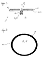
- FIG. 1 illustrates the basic principle of the optical mode of action of the insect trap 10.
- a trap surface 18 which consists of a bright surface 12 and disposed within the bright surface 12 contrast point 16.
- the contrast point 16 is significantly darker than the bright surface 12, in particular black.
- the entire surface 18 or parts thereof can simultaneously function as outflow surface 14, which emits a weak air flow 22 (cf. FIGS. 3, 5, 7 and 9).
- What is shown in the following figures as a round trap surface 18 can also have any other conceivable contour.
- the trap surface 18 also does not have to be flat, but can also be curved inwards or outwards.
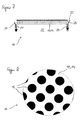
- Figure 2 illustrates a simple first variant of the insect trap 10 in a schematic cross section, but not according to the invention.
- Recognizable here is the uniformly bright surface 12 on the trap surface 18 and the approximately centrally arranged contrast point 16.
- the dark contrast 16 may in this case preferably be treated with glue or an insecticide so that the approaching insects are trapped and / or killed.
- FIG. 3 illustrates in a further schematic cross section a second variant of an insect trap 10, in which the bright surface 12 is designed as an outflow surface 14.
- the bright surface 12 is designed as an outflow surface 14.
- a uniform, weak air flow 22 which preferably has a flow velocity of less than 100 cm / s.
- the flow velocity of the weak air flow 22 may be about 5 to 20 cm / s and is thus capable of heat convection flow of a human or animal skin imitate that it is considered attractive to insects.
- the weak air flow 22 can emerge, in particular, through an outflow surface 14 formed as a tissue.
- the contrasting point 16 in the center of the outflow surface 14 configured as a light surface 12 may also be designed as an outflow surface.
- this second variant makes use of the mechanical attraction of the weak air flow, which is considered attractive for many insects, since it is modeled on the heat convection flow of a skin surface.
- Experiments have shown the surprising effect that blood-sucking insects are attracted to such air flow and apparently hold it for a heat convection flow of a body.
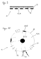
- FIG. 4 shows a variant of the insect trap 10 in a schematic cross section, but not according to the invention.
- This variant provides for a weak air flow 22 outside the bright area 12.
- the contrast point 16 is designed as a suction port 24, in the illustrated embodiment as an intake passage 26 through which a suction flow 25 is generated in a cavity 20 of the insect trap 10.
- the weak air flow 22 can serve in this variant of the insect trap 10 optionally as a means of transport for an attractant, which is attractive to the insects to be attracted.
- the attractant may mimic exudates of a human or animal body and consist of several components that are combined to form a fragrance mixture when released to the air flow 22.
- the intake flow 25 is at least so strong that insects entering a vicinity of the trap are drawn into the intake passage 26 and can no longer leave it.
- this acts as a contrast point 16, so that this trap variant combines an optical stimulus with a mechanical (air flow) and / or an olfactory stimulus (attractant).
- FIG. 5 shows a schematic cross section of a further variant of the insect trap 10 according to the invention, in which the bright surface 12 is designed as an outflow surface 14, through which the weak air flow 22 passes.
- the contrast point 16 is in turn formed as a dark-lined suction port 24 or channel 26 through which a stronger suction flow 25 at a flow rate of more than 1 m / s, preferably of up to 2 m / s or more passes.
- the weak air flow 22 can also transport an attractant here.
- FIGS. 6 and 7 show an alternative variant of an insect trap 10, in which the trap surface 18 is designed as a light surface 12 with an intake opening 24 arranged annularly around it.
- the suction opening 24 serves to generate a suction flow 25 into the cavity 20 of the insect trap 10.
- the bright surface 12 is formed as an outflow surface 14, through which a weak air flow 22 passes.
- the airflow 22 may optionally transport an attractant as previously described.
- FIGS. 8 and 9 show a further alternative variant, in which a plurality of dark contrasting points 16 are arranged on a light surface 12.
- a plurality of dark contrasting points 16 are arranged on a light surface 12.
- the bright surface 12 or the entire trap surface 18 may be formed as an outflow surface 14, through which the weak air flow 22 passes to the outside.
- the weak air flow can serve as a means of transport for an attractant.
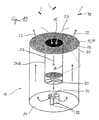
- the insect trap 10 comprises a cavity 20 within a hollow cylindrical body whose end face 32 is formed as a trap surface 18.
- the trap surface 18 comprises a bright surface 12, which is designed as an outflow surface 14 and has a center point 16 arranged in it contrast point, which is formed in the illustrated embodiment as an intake passage 26 with dark-lined inner circumferential surface 28.
- the bright surface 12 may in particular be formed by a fabric 15, which is stretched on the hollow cylindrical trap and through which the weak air flow 22 passes to the outside.
- a blower or a fan 30 is provided which generates the intake flow 25 into the cavity 20 of the insect trap 10.
- a plurality of attractant containers 38 can be seen, through each of which a component of an attractant 40 is delivered evenly and in a desired concentration, so that the attractant 40 delivered in a desired, optimal mixing ratio to the outside and into the weak air flow 22 becomes.
- the bright surface 12 and the diameter of the intake duct 26 are preferably matched to one another such that the single fan 30 ensures both the desired intake flow of approximately 2 m / s and the desired low air flow of approximately 5 to 20 cm / s can.
- a tissue is also mounted in front of the fan 30, which prevents the insects from entering the interior of the trap.
- a particularly advantageous embodiment may consist in that the intake duct 26 is provided with an insert which can be removed and emptied as soon as enough insects are trapped therein.
- the intake air flow 25 is to be designed at least so strong that in the vicinity of the trap 10 located insects 42 are sucked into the intake passage 26 and can not leave this.
- FIG. 11 shows a schematic representation of an alternative embodiment of the insect trap 10, which is formed in this case as a spherical body.
- the spherical surface 36 of the insect trap 10 may optionally be formed as an outflow surface 14.
- a plurality of intake passages 26 are arranged distributed over the spherical surface, so that at least one dark contrast point 16 on the bright spherical surface can be seen from any perspective.
- the spherical insect trap 10 according to FIG. 11 can have a greater effectiveness owing to its substantially larger effective surface than the cylindrical variant of FIG. 10, since the optical component acts in all directions with the dark contrasting points 16 of the suction channels 26.
- this can optionally additionally serve as a transport medium for an attractant 40.
- the weak air flow 22 simulates a heat convection flow of a human or animal body.
- the attractant 40 can in particular emulate human or animal exhalations. Alternatively, however, other attractants may be used which are attractive to the insects to be attracted.
- the contrasting point 16 arranged inside the bright area 12 is preferably sufficiently dark that it is recognized as an optical stimulus signal by the insects 42 to be attracted.
- FIG. 12 shows a freely suspended trap 10, but not according to the invention, with a cover 44 arranged above it and spaced therefrom.
- the trap 10 can have any shape, for example a hollow cylindrical or spherical one according to FIGS. 10 or 11.
- the cover 44 may optionally be transparent to expose the bright surface 12 of the trap 10 with the dark contrast 14 located therein for the insects.
- the cover 44 itself may be formed as a light surface with a dark contrasting point disposed therein to attract the insects from further distance.
- the insect trap according to the invention is particularly suitable for mosquitoes, mosquitoes and other stinging and / or blood sucking insect species.
Landscapes
- Life Sciences & Earth Sciences (AREA)
- Pest Control & Pesticides (AREA)
- Engineering & Computer Science (AREA)
- Insects & Arthropods (AREA)
- Wood Science & Technology (AREA)
- Zoology (AREA)
- Environmental Sciences (AREA)
- Health & Medical Sciences (AREA)
- General Health & Medical Sciences (AREA)
- Toxicology (AREA)
- Catching Or Destruction (AREA)
- Agricultural Chemicals And Associated Chemicals (AREA)
Description
- Die Erfindung betrifft eine Insektenfalle, insbesondere für Flug- und/oder Schädlingsinsekten mit den Merkmalen des Oberbegriffs des unabhängigen Patentanspruchs 1, siehe z.B Dokument CA-A- 1 227 929.
- Blutsaugende Insekten zählen zu den bedeutendsten Hygieneschädlingen weltweit, da sie zahlreiche Krankheiten auf Mensch (bspw. Malaria, Gelbfieber, Dengue u.a.) und Tiere übertragen und zudem ausgesprochen lästig sein können. Eine Möglichkeit zur großflächigen Bekämpfung dieser Schädlinge ist der Einsatz von Insektiziden. Eine weitere Möglichkeit zur Kontrolle und Bekämpfung von Schadinsekten ist der Einsatz von Fallensystemen, die sich jedoch vorwiegend nur für kleinere Bereiche, insbesondere für geschlossene Räume eignen.
- Insektenfallen sind in vielen Ausführungsformen und Varianten bekannt. Einfache Varianten bestehen beispielsweise in Leimruten, die mit Lockstoffen versehen sind und auf denen die Insekten nach einem Kontakt festgehalten werden. Andere Varianten emittieren ultraviolettes Licht oder Ultraschall und versuchen auf diese Weise, Schadinsekten anzulocken. Es sind auch Vorrichtungen bekannt, die Geruchs- und Lockstoffe aussenden, beispielsweise mit Hilfe einer Luftströmung, wonach die dadurch angelockten Insekten mit Hilfe einer gegensinnigen Luftströmung in einen Hohlraum eingesaugt und dort gefangen gehalten werden.
- Derartige Fallensysteme sind beispielsweise in der US 2001/004 50 51 A1 und in der US 62 86 249 B1 beschrieben. Bei dieser Fallenart wird ein Lockstoff durch ein innerhalb eines zylindrischen Rohres angeordneten Gebläses verteilt und soll für das Anlocken von Insekten sorgen. Sobald diese in die Nähe der Falle gelangen, werden sie durch einen Luftstrom angesaugt und in das Innere der Falle gezogen. Hierzu ist um das zylindrische Rohr ein weiteres Rohr angeordnet. Im Zwischenraum zwischen den beiden konzentrisch angeordneten Rohren wird eine Saugströmung erzeugt, die für das Ansaugen der Insekten in das Falleninnere sorgt.
- Bei bekannten Fallenvarianten wird insbesondere Kohlendioxid verströmt, da dieses Gas von den Insekten als Bestandteil der menschlichen und tierischen Atemluft erkannt und damit als attraktiv empfunden wird.
- Die Wirksamkeit und Effektivität der bisher bekannten Fallensysteme ist allerdings durchweg begrenzt, da sie meist nicht für das gewünschte weitgehende Unschädlichmachen der in einem Raum oder in einer Umgebung befindlichen Insekten sorgen können. Zudem sind die Fallensysteme, bei denen Kohlendioxid verströmt wird, relativ teuer in der Anschaffung und im Betrieb.
- Ein Ziel der vorliegenden Erfindung besteht darin, eine Insektenfalle zur Verfügung zu stellen, die einfach aufgebaut, zudem kostengünstig und dabei möglichst effektiv ist.
- Dieses Ziel der Erfindung wird mit dem Gegenstand des unabhängigen Patentanspruchs erreicht. Merkmale vorteilhafter Weiterbildungen der Erfindung ergeben sich aus den jeweiligen abhängigen Ansprüchen.
- Ein erster Aspekt einer erfindungsgemäßen Insektenfalle, die insbesondere zum Anlocken von Flug- und/oder Schädlingsinsekten dient, weist eine ebene oder eine gewölbte, helle Fläche und wenigstens eine innerhalb dieser Fläche angeordnete, dunkle Kontraststelle auf. Die Insektenfalle weist weiterhin Einrichtungen zum Festhalten, Fangen und/oder zum Abtöten von angelockten Insekten auf einer Oberfläche der Falle und/oder in einem darin angeordneten Hohlraum auf. Bei diesem ersten Aspekt einer Insektenfalle wird sich die Erkenntnis zu Nutze gemacht, dass dunkle Objekte für viele Insekten eine Signalwirkung hat und diese anlockt. Versuche mit diesem erfindungsgemäßen Fallenaspekt haben gezeigt, dass eine helle Oberfläche mit einem darin angeordneten dunklen Fleck, bspw. in deren Mitte, für bestimmte Insekten sehr attraktiv ist und diese anlockt. Bisher war lediglich bekannt, dass dunkle Objekte in der Lage sein können, bestimmte Insektenarten anzulocken. Die Erfindung macht sich die bessere Signalwirkung einer dunklen Kontraststelle auf einer hellen Oberfläche zu Nutze.
- Ein zweiten Aspekt der Insektenfalle weist eine Ausströmfläche zur Erzeugung bzw. zur Abgabe einer von der Fläche ausgehenden, schwachen Luftströmung sowie Einrichtungen zum Festhalten, Fangen und/oder Abtöten von angelockten Insekten auf einer Oberfläche der Falle und/oder in einem darin angeordneten Hohlraum auf. Bei Versuchen hat sich der überraschende Effekt gezeigt, dass eine großflächige, schwache und gleichmäßig verteilte Luftströmung für viele Schadinsekten ebenfalls attraktiv ist und diese anlocken kann. Erklären lässt sich dies damit, dass die großflächige, schwache Luftströmung einer von einem menschlichen oder tierischen Körper abgegebenen Wärmeströmung gleicht, die von vielen Insekten, insbesondere von Stechmücken (aedes aegypti) und Blut saugenden Insekten erkannt und als attraktiv empfunden wird.
- Erfindungsgemäβ ist eine helle Fläche mit einer dunklen Kontraststelle gleichzeitig mit einer Ausströmfläche versehen oder als solche ausgebildet ist. Hierdurch lässt sich die Effektivität der Falle verbessern.
- Eine Ausführungsform der erfindungsgemäßen Insektenfalle sieht vor, dass zumindest die helle Fläche mit Leim und/oder einem Insektizid versehen ist.
- Zusätzlich kann auch die dunkle Kontraststelle mit Leim und/oder einem Insektizid versehen sein, so dass die Oberfläche der Falle als Haftmittel für die angelockten Insekten fungieren kann. Alternativ können die Insekten bei einem Kontakt mit einer Fallenoberfläche abgetötet werden. Dies kann auch durch eine Beaufschlagung einer Oberfläche der Insektenfalle mit einer elektrischen Spannung, beispielsweise mit Hilfe eines unter Spannung stehenden Drahtgitters oder dergleichen erreicht werden.
- Die von der Ausströmfläche emittierte, schwache Luftströmung weist vorzugsweise eine mittlere Strömungsgeschwindigkeit zwischen 2 und 100 cm/s, besser zwischen 3 und 50 cm/s, vorzugsweise jedoch von 5 bis 20 cm/s auf, so dass die schwache Luftströmung besonders gut die von einem menschlichen oder tierischen Körper erzeugte Konvektionsströmung der Luft imitieren kann.
- Eine besonders bevorzugte Ausführungsform der Insektenfalle sieht vor, dass zusätzlich von der Falle ein Lockstoff emittiert wird. Hierbei wird sich die Erkenntnis zunutze gemacht, dass der Geruch eines menschlichen oder tierischen Körpers für Insekten dann besonders attraktiv ist, wenn er in einer schwachen, gleichmäßig verteilten Luftströmung transportiert wird. Es sind Fallen bekannt, mit denen Kohlendioxid verteilt wird. Dies ist ein Lockstoff, der auch in der Atemluft enthalten ist. Eine derartige Kohlendioxidabgabe ist dann für Insekten besonders attraktiv, wenn die Strömung diskontinuierlich ist und in Duftfilamenten angeboten wird. Dagegen wird ein den Hautgeruch imitierender Lockstoff insbesondere dann von den Insekten als attraktiv empfunden, wenn er in einer schwachen Luft- bzw. Konvektionsströmung transportiert wird, wie es die vorliegenden Erfindung vorsieht.
- Vorzugsweise kann der Lockstoff von Teilen oder der gesamten hellen Fläche emittiert werden. Der Lockstoff kann beispielsweise in einer Beschichtung der hellen Fläche gebunden und in einer definierbaren Konzentration abgegeben werden. Hierfür eignet sich beispielsweise ein Bindemittel auf der hellen und/oder dunklen Fläche, in dem die flüchtigen Lockstoffe gelöst sind und in definierbarer Konzentration abgegeben werden. Ein solches Bindemittel kann insbesondere Leim sein, auf dem anfliegende Insekten haften bleiben. Damit der Lockstoff gleichmäßig abgegeben wird und in einer Konvektionsströmung transportiert wird, kann eine Beheizung der Fallenoberfläche vorgesehen sein, bspw. mittels Heizdrähten oder dergleichen.
- Erfindungsgemäβ sieht eine Kombination der olfaktorischen und der visuellen Reize für die Insekten vor wobei die Ausströmfläche als helle Fläche mit wenigstens einer innerhalb dieser angeordneten, dunklen Kontraststelle ausgebildet ist. Die helle Fläche weist eine Größe von typischerweise wenigstens 30 cm2 auf, sollte vorzugsweise jedoch eine Größe von mindestens 100 cm2 aufweisen, um den gewünschten Effekt auch auf größerer Entfernung auszuüben. Eine solch kombinierte, optische und olfaktorische Wirkung der erfindungsgemäßen Insektenfalle imitiert besonders gut menschliche und tierische Körper, so dass eine solche Falle eine hohe Attraktivität und damit eine hohe Wirksamkeit für viele Insekten, insbesondere für Blut saugende Arten, aufweist.
- Eine weitere Ausführungsform der Erfindung sieht vor, dass wenigstens eine Ansaugöffnung zum Ansaugen von angelockten Insekten vorgesehen ist. Alternativ können auch mehrere Ansaugöffnungen um die helle Fläche bzw. um die Ausströmfläche angeordnet sein. Es kann insbesondere auch eine ringförmige Ansaugöffnung um die helle Fläche ausgebildet sein. Hierdurch können die angelockten Insekten in einen Hohlraum oder einen Behälter eingesaugt werden, in dem sie gesammelt und aus dem sie nicht mehr fliehen können. Gegebenenfalls kann in diesem Hohlraum ein Insektizid eingebracht sein, so dass die Insekten an Ort und Stelle abgetötet werden.
- Eine bevorzugte Ausgestaltung der Erfindung sieht vor, dass die dunkle Kontraststelle als dunkler Ansaugkanal ausgebildet ist. D.h., eine Innenmantelfläche des rohrförmigen Ansaugkanals ist vorzugsweise dunkel beschichtet, so dass der Ansaugkanal selbst als dunkle Kontraststelle auf der hellen Fläche wirken kann. Eine Strömungsgeschwindigkeit am bzw. im Ansaugkanal bzw. in der wenigstens einen Ansaugöffnung beträgt vorzugsweise mehr als 1 m/s und kann in bevorzugter Ausgestaltung ca. 2 m/s betragen. Auf diese Weise kann sichergestellt werden, dass Insekten, die in die Nähe des Ansaugkanals oder der Ansaugöffnung gelangen, zuverlässig eingesaugt werden und nicht mehr fliehen können. Gleichzeitig wird sichergestellt, dass die Insekten nicht gegen die Luftströmung anfliegen können und beispielsweise nach ihrem Fangen den Hohlraum wieder verlassen können.
- Eine weitere bevorzugte Ausführungsform der Erfindung sieht wenigstens einen in der Falle angeordneten Ventilator zur Erzeugung der Ansaugströmung und/oder der schwachen Luftströmung aus der Ausströmfläche vor. Der Ventilator kann insbesondere eine Ringströmung erzeugen, wobei ein Sog durch die Ansaugöffnung bzw. durch den Ansaugkanal erzeugt und die hier eingesaugte Luft wieder über die größere Ausströmfläche als gleichmäßige, schwache Luftströmung abgegeben wird. Die Größenverhältnisse des Ansaugkanals und der Ausströmfläche müssen in diesem Fall so aufeinander abgestimmt werden, dass die gewünschten Luftgeschwindigkeiten erreicht werden.
- Vorzugsweise ist eine innerhalb der Falle angeordnete Einrichtung zur gleichmäßigen Abgabe des Lockstoffs vorgesehen. Eine solche Einrichtung kann insbesondere aus mehreren Flakons mit den Einzelkomponenten des Lockstoffs oder aus unterschiedlichen Röhrchen mit darin angeordneten Lockstoffkomponenten bestehen, da der Lockstoff typischerweise nicht als Gemisch, sondern in Einzelkomponenten aufbewahrt werden muss und erst bei der Abgabe an die Luft zu einem Lockstoffgemisch wird. Als derartiger Lockstoff kommt insbesondere ein Gemisch aus Milchsäure, Capronsäure und Ammoniak in Frage, wie er beispielsweise in der provisorischen US-Anmeldung Nr. 60/386,582 vom 07.06.2002 offenbar ist. Die in dieser Anmeldung genannten Wirkstoff- und Lockstoffkombinationen und -gemische werden hiermit ausdrücklich in den Offenbarungsumfang der vorliegenden Anmeldung miteinbezogen.
- Die Ausströmfläche kann eine Bespannung mit einem hellen Gewebe aufweisen, deren Maschenweite kleiner ist als die Größe der angelockten Insekten. Auf diese Weise kann einerseits die helle Fläche gebildet und andererseits die Falle nach außen hin abgeschlossen werden, so dass darin gefangene Insekten nicht mehr durch das Gewebe hindurchfliegen können.
- Der Ansaugkanal weist vorzugsweise eine Mindestlänge auf, die eine ausreichend gleichmäßige Strömung im Kanal und in unmittelbarer Nähe des Kanals bewirkt. Eine typische Länge des Ansaugkanals kann beispielsweise zwischen 5 und 10 cm oder mehr betragen. Ein typischer Durchmesser des Ansaugkanals kann beispielsweise zwischen 3 und 15 cm betragen. Die Abmessungen der Ausströmfläche und des Ansaugkanals richten sich insbesondere nach der gewünschten Größe der Falle und nach den gewünschten Verhältnissen der Strömungsgeschwindigkeiten im Kanal und aus der Ausströmrichtung. Auch die typische Größe der bevorzugt angelockten Insekten beeinflusst die sinnvollen Abmessungen des Ansaugkanals und der Falle.
- Eine Ausgestaltung der Erfindung sieht eine zusätzliche Gewebebespannung vor dem Ventilator vor, so dass die angesaugten Insekten nicht in das Falleninnere gelangen, sondern an der Unterseite des Ansaugkanals gesammelt werden. Eine vorteilhafte Ausgestaltung sieht ein Einsatzmodul vor dem Ventilator im Kanal vor, das gegebenenfalls mit einem Klebstoff oder mit einem Insektizid versehen sein kann und das in regelmäßigen Abständen aus der Falle entnommen und entleert werden kann. Um zu verhindern, dass die angesaugten Insekten wieder fliehen können, kann bspw. sichergestellt werden, dass das Ventilatorgebläse permanent läuft. Soll der Ventilator nicht permanent laufen, kann es vorteilhaft sein, eine reusenartigen Fangbehälter vorzusehen, aus dem die Insekten nicht mehr fliehen können. Bei einer solchen Variante kann das Gebläse wahlweise in einem Intervallbetrieb laufen.
- Eine bevorzugte Form der erfindungsgemäßen Insektenfalle sieht einen hohlzylindrischen Körper mit stirnseitig angeordneter Ausströmfläche und einen ins Innere des hohlzylindrischen Körpers führenden, dunklen Ansaugkanal vor. Die Stirnfläche kann wahlweise nach außen oder nach innen gewölbt sein. Weiterhin ist vorzugsweise eine geschlossene Bodenfläche mit darauf angeordneter Einrichtung zur Abgabe des Lockstoffs vorgesehen.
- Die Stirnfläche der hohlzylindrischen Falle weist vorzugsweise nach oben. Die Falle weist damit gegenüber einer Falle, die Kohlendioxid verströmt, den Vorteil einer besseren Erkennbarkeit für Insekten auf, da diese die helle Oberfläche bzw. den ausströmenden Lockstoff besser wahrnehmen können als bei einer nach unten weisenden Wirkfläche der Falle. Kohlendioxidfallen verströmen dieses normalerweise nach unten, da das CO2 schwerer als Luft ist und nach unten sinkt.
- Eine alternative Ausgestaltung der Erfindung sieht eine Falle in Kugelform mit einem oder mehreren über deren Oberfläche verteilt angeordneten Ansaugkanälen vor. Zumindest Teile der Kugeloberfläche können als Ausströmöffnungen ausgebildet sein. Vorzugsweise jedoch ist bei einer solchen Insektenfalle weitgehend die gesamte Kugeloberfläche als Ausströmöffnung ausgebildet.
- Eine weitere erfindungsgemäße Ausgestaltung sieht eine oberhalb der Falle und beabstandet zu dieser angeordneten Abdeckung, die als Witterungsschutz dient. Die Abdeckung kann insbesondere verhindern, dass Regen die Falle in ihrer Wirkung beeinträchtigen oder unwirksam machen kann. Die Abdeckung kann wahlweise transparent sein, damit die Insekten die helle Fläche mit dem dunklen Kontrastfleck wahrnehmen können. Alternativ hierzu kann die Abdeckung selbst als optisches Lockmittel ausgestaltet sein. Hierzu kann sie insbesondere als helle Fläche mit einem oder mehreren dunklen Kontraststellen ausgestaltet sein.
- Die Falle ist vorzugsweise frei aufgehängt, bspw. an einer Schnur oder Kette, mittels derer sie an einem Baum, einem Gestell oder einer anderen geeigneten Stelle aufgehängt sein kann.
- Die erfindungsgemäßen Insektenfallen eignen sich nicht nur zur Schädlingsbekämpfung in geschlossenen Räumen und im Freien, sondern auch zur Erfassung einer Insektendichte in einem bestimmten Gebiet. Bei diesem sog. Monitoring werden derartige Fallen in einem zu überwachenden Gebiet während einer vorbestimmten Zeitdauer aufgestellt, wonach die Menge der gefangenen Insekten gemessen wird. Dieses Monitoring kann insbesondere dazu dienen, die Notwendigkeit bzw. die Effektivität von Schädlingsbekämpfungsmaßnahmen vor deren Durchführung zu bestimmen und/oder nachträglich zu messen.
- Die Erfindung wird nachfolgend anhand bevorzugter Ausführungsbeispiele unter Bezugnahme auf die beiliegenden Zeichnungen näher erläutert. Dabei zeigt:
- Figur 1
- eine schematische Draufsicht auf eine Fallenoberfläche einer Insektenfalle,
- Figur 2
- ein schematischer Querschnitt einer ersten Variante der Insektenfalle, aber nicht gemäß der Erfindung,
- Figuren 3 bis 5
- alternative Varianten von Insektenfallen in schematischen Querschnittdarstellungen,
- Figur 6
- eine schematische Draufsicht auf eine weitere alternative Variante einer Insektenfalle,
- Figur 7
- ein schematischer Querschnitt des Fallenprinzips der Figur 6,
- Figur 8
- eine weitere Variante einer Insektenfalle in schematischer Draufsicht,
- Figur 9
- ein schematischer Querschnitt der Falle gemäß Figur 8,
- Figur 10
- eine schematische Perspektivdarstellung einer erfindungsgemäßen I nsektenfalle,
- Figur 11
- eine Prinzipdarstellung einer alternativen Variante einer erfindungsgemäßen Insektenfalle und
- Figur 12
- eine frei aufgehängte Falle mit einer Abdeckung, aber nicht gemäß der Erfindung
- Die schematische Draufsicht der Figur 1 verdeutlicht das Grundprinzip der optischen Wirkungsweise der Insektenfalle 10. Diese weise eine Fallenoberfläche 18 auf, die aus einer hellen Fläche 12 und einer innerhalb der hellen Fläche 12 angeordneten Kontraststelle 16 besteht. Die Kontraststelle 16 ist gegenüber der hellen Fläche 12 deutlich dunkler, insbesondere schwarz. Die gesamte Oberfläche 18 oder Teile davon kann je nach Ausgestaltung der Insektenfalle 10 gleichzeitig als Ausströmfläche 14 fungieren, die eine schwache Luftströmung 22 abgibt (vgl, hierzu die Figuren 3, 5, 7 und 9). Was in den folgenden Figuren als runde Fallenoberfläche 18 gezeigt ist, kann ebenso jede andere denkbare Kontur aufweisen. Die Fallenoberfläche 18 muss auch nicht eben, sondern kann ebenso gut nach innen oder außen gewölbt sein.
- Figur 2 verdeutlicht eine einfache erste Variante der Insektenfalle 10 in einem schematischen Querschnitt, aber nicht gemäß der Erfindung. Erkennbar ist hierbei die gleichmäßig helle Fläche 12 auf der Fallenoberfläche 18 und die ungefähr mittig angeordnete Kontraststelle 16. Eine solche Falle arbeitet ausschließlich auf Basis eines optischen Reizes, da ein dunkler oder schwarzer Kontrast gegenüber einer hellen Oberfläche für viele Insekten als attraktiv empfunden und bevorzugt angeflogen wird. Die dunkle Kontraststelle 16 kann in diesem Fall vorzugsweise mit Leim oder einem Insektizid behandelt sein, so dass die anfliegenden Insekten gefangen und/oder abgetötet werden.
- Figur 3 verdeutlicht in einem weiteren schematischen Querschnitt eine zweite Variante einer Insektenfalle 10, bei der die helle Fläche 12 als Ausströmfläche 14 ausgebildet ist. Aus dieser Ausströmfläche 14 tritt eine gleichmäßige, schwache Luftströmung 22 aus, die vorzugsweise eine Strömungsgeschwindigkeit von weniger von 100 cm/s aufweist. Insbesondere kann die Strömungsgeschwindigkeit der schwachen Luftströmung 22 bei ca. 5 bis 20 cm/s liegen und ist dadurch in der Lage, eine Wärmekonvektionsströmung einer menschlichen oder tierischen Haut so nachzubilden, dass sie für Insekten als attraktiv empfunden wird. Die schwache Luftströmung 22 kann insbesondere durch eine als Gewebe ausgebildete Ausströmfläche 14 austreten. Auch die Kontraststelle 16 in der Mitte der als helle Fläche 12 ausgestalteten Ausströmfläche 14 kann als Ausströmfläche ausgebildet sein. Diese zweite Variante macht sich neben der optischen Wirkung des dunklen Kontrastflecks in der Mitte den mechanischen Reiz der schwachen Luftströmung zunutze, der für viele Insekten als attraktiv empfunden wird, da sie der Wärmekonvektionsströmung einer Hautoberfläche nachgebildet ist. Es hat sich bei Versuchen der überraschende Effekt gezeigt, dass Blut saugende Insekten von einer solchen Luftströmung angezogen werden und sie offenbar für eine Wärmekonvektionsströmung eines Körpers halten.
- Figur 4 zeigt eine Variante der Insektenfalle 10 in einem schematischen Querschnitt, aber nicht gemäß der Erfindung. Diese Variante sieht eine schwache Luftströmung 22 außerhalb der hellen Fläche 12 vor. Weiterhin ist die Kontraststelle 16 als Ansaugöffnung 24 ausgestaltet, im gezeigten Ausführungsbeispiel als Ansaugkanal 26, durch den eine Ansaugströmung 25 in einen Hohlraum 20 der Insektenfalle 10 erzeugt wird. Die schwache Luftströmung 22 kann bei dieser Variante der Insektenfalle 10 wahlweise als Transportmittel für eine Lockstoff dienen, der für die anzulockenden Insekten attraktiv ist. Der Lockstoff kann insbesondere Ausdünstungen eines menschlichen oder tierischen Körpers nachahmen und aus mehreren Komponenten bestehen, die bei der Abgabe an die Luftströmung 22 zu einem Duftgemisch zusammengesetzt werden.
- Die Ansaugströmung 25 ist zumindest so stark, dass in einen Nahbereich der Falle gelangende Insekten in den Ansaugkanal 26 eingezogen werden und diesen nicht mehr verlassen können. Bei einer dunklen Beschichtung einer Innenmantelfläche 28- des Ansaugkanals 26 wirkt dieser als Kontraststelle 16, so dass diese Fallenvariante einen optischen Reiz mit einem mechanischen (Luftströmung) und/oder einem olfaktorischen Reiz (Lockstoff) kombiniert. Mit einer solchen Wirkkombination sind besonders hohe Fangraten erzielbar, da die Insekten auf mehrfache Weise angesprochen und angelockt werden.
- Die Figur 5 zeigt einen schematischen Querschnitt einer weiteren Variante der erfindungsgemäßen Insektenfalle 10, bei der die helle Fläche 12 als Ausströmfläche 14 ausgestaltet ist, durch die die schwache Luftströmung 22 hindurchtritt. Die Kontraststelle 16 ist wiederum als dunkel ausgekleidete Ansaugöffnung 24 bzw. -kanal 26 ausgebildet, durch die/den eine stärkere Ansaugströmung 25 mit einer Strömungsgeschwindigkeit von mehr als 1 m/s, vorzugsweise von bis zu 2 m/s oder mehr hindurchtritt. Durch den Ansaugkanal 26 werden die von der schwachen Luftströmung 22 bzw. der Kontraststelle 16 angelockten Insekten in das Falleninnere des Hohlraums 20 angesaugt. Wahlweise kann auch hier die schwache Luftströmung 22 einen Lockstoff transportieren.
- Die Figuren 6 und 7 zeigen eine alternative Variante einer Insektenfalle 10, bei denen die Fallenoberfläche 18 als helle Fläche 12 mit einer um diese ringförmig angeordneten Ansaugöffnung 24 ausgebildet ist. Die Ansaugöffnung 24 dient zur Erzeugung einer Ansaugströmung 25 in den Hohlraum 20 der Insektenfalle 10. Auch hier ist die helle Fläche 12 als Ausströmfläche 14 ausgebildet, durch die eine schwache Luftströmung 22 hindurchtritt. Die Luftströmung 22 kann wahlweise einen Lockstoff, wie zuvor beschrieben, transportieren.
- Die Figuren 8 und 9 zeigen eine weitere alternative Variante, bei der mehrere dunkle Kontraststellen 16 auf einer hellen Fläche 12 angeordnet sind. Hierbei kann wahlweise nur die helle Fläche 12 oder die gesamte Fallenoberfläche 18 als Ausströmfläche 14 ausgebildet sein, durch die die schwache Luftströmung 22 nach außen tritt. Auch bei dieser Variante kann die schwache Luftströmung als Transportmittel für einen Lockstoff dienen.
- Anhand der Figur 10 wird ein prinzipieller Aufbau der gesamten Insektenfalle 10 verdeutlicht. Die Insektenfalle 10 umfasst einen Hohlraum 20 innerhalb eines hohlzylindrischen Körpers, dessen Stirnfläche 32 als Fallenoberfläche 18 ausgebildet ist. Die Fallenoberfläche 18 umfasst eine helle Fläche 12, die als Ausströmfläche 14 ausgebildet ist und eine mittig darin angeordnete Kontraststelle 16 aufweist, die im gezeigten Ausführungsbeispiel als Ansaugkanal 26 mit dunkel ausgekleideter Innenmantelfläche 28 ausgebildet ist. Die helle Fläche 12 kann insbesondere durch ein Gewebe 15 gebildet sein, das auf die hohlzylindrische Falle gespannt ist und durch das die schwache Luftströmung 22 nach außen tritt.
- Am unteren Ende des Ansaugkanals 26 ist ein Gebläse bzw. ein Ventilator 30 vorgesehen, der die Ansaugströmung 25 in den Hohlraum 20 der Insektenfalle 10 erzeugt. An einer Bodenfläche 34 des Hohlraums 20 sind mehrere Lockstoffbehälter 38 erkennbar, durch die jeweils eine Komponente eines Lockstoffs 40 gleichmäßig und in einer gewünschten Konzentration abgegeben wird, so dass der Lockstoff 40 in einem gewünschten, optimalen Mischungsverhältnis nach außen und in die schwache Luftströmung 22 abgegeben wird. Die helle Fläche 12 und der Durchmesser des Ansaugkanals 26 sind vorzugsweise so aufeinander abgestimmt, dass der einzige Ventilator 30 sowohl für die gewünschte Ansaugströmung von ca. 2 m/s als auch für die gewünschte schwache Luftströmung von ca. 5 bis 20 cm/s sorgen kann. Vorzugsweise ist auch vor dem Ventilator 30 ein Gewebe angebracht, das die Insekten daran hindert, in das Innere der Falle zu gelangen.
- Eine besonders vorteilhafte Ausgestaltung kann darin bestehen, dass der Ansaugkanal 26 mit einem Einsatz versehen ist, der entnommen und entleert werden kann, sobald genug Insekten darin gefangen sind.
- Die Ansaugluftströmung 25 ist zumindest so stark auszulegen, dass im Nahbereich der Falle 10 befindliche Insekten 42 in den Ansaugkanal 26 eingesaugt werden und diesen nicht mehr verlassen können.
- Figur 11 zeigt eine schematische Darstellung einer alternativen Ausgestaltung der Insektenfalle 10, die in diesem Fall als Kugelkörper ausgebildet ist. Die Kugeloberfläche 36 der Insektenfalle 10 kann wahlweise als Ausströmfläche 14 ausgebildet sein. Vorzugsweise sind mehrere Ansaugkanäle 26 über die Kugeloberfläche verteilt angeordnet, so dass aus jeder Perspektive zumindest eine dunkle Kontraststelle 16 auf der hellen Kugeloberfläche erkennbar ist. Die kugelförmige Insektenfalle 10 entsprechend Figur 11 kann aufgrund ihrer wesentlich größeren wirksamen Oberfläche gegenüber der zylindrischen Variante der Figur 10 eine größere Effektivität aufweisen, da die optische Komponente mit den dunklen Kontraststellen 16 der Ansaugkanäle 26 in alle Richtungen wirkt.
- Bei allen beschriebenen Varianten, die eine durch die Ausströmfläche 14 austretende schwache Luftströmung 22 aufweisen, kann diese wahlweise zusätzlich als Transportmedium für einen Lockstoff 40 dienen. Die schwache Luftströmung 22 bildet eine Wärmekonvektionsströmung eines menschlichen oder tierischen Körpers nach. Der Lockstoff 40 kann insbesondere menschliche oder tierische Ausdünstungen nachbilden. Wahlweise können jedoch auch andere Lockstoffe verwendet werden, die für die anzulockenden Insekten attraktiv sind.
- Die innerhalb der hellen Fläche 12 angeordnete Kontraststelle 16 ist vorzugsweise ausreichend dunkel, so dass sie als optisches Reizsignal von den anzulockenden Insekten 42 erkannt wird. Durch Versuche konnte ermittelt werden, dass einzelne dunkle Kontraststellen auf hellem Hintergrund eine anlockende Signalwirkung auf viele Insekten ausüben, so dass eine Anordnung gemäß der Erfindung als optische Reizkomponente einer Insektenfalle genutzt werden kann.
- Figur 12 zeigt schließlich eine frei aufgehängte Falle 10, aber nicht gemäß der Erfindung, mit einer oberhalb dieser und beabstandet zu dieser angeordneten Abdeckung 44. Die Falle 10 kann eine beliebige Form haben, bspw. eine hohlzylindrische oder kugelige entsprechend den Figuren 10 oder 11. Die Abdeckung 44 kann wahlweise transparent sein, um die helle Fläche 12 der Falle 10 mit der darin angeordneten dunklen Kontraststelle 14 für die Insekten sichtbar zu lassen. Alternativ kann die Abdeckung 44 selbst als helle Fläche mit darin angeordneter dunkler Kontraststelle ausgebildet sein, um die Insekten schon von weiterer Entfernung anlocken zu können.
- Die erfindungsgemäße Insektenfalle eignet sich insbesondere für Stechmücken, Moskitos und andere stechende und/oder Blut saugende Fluginsektenarten.
Claims (10)
- lnsektenfalle, insbesondere für Flug- und/oder Schädlingsinsekten, mit einer ebenen oder gewölbten, hellen Fläche (12) und mit einer Ausströmfläche (14) zur Erzeugung einer von der Fläche (14) ausgehenden, schwachen Luftströmung (22), und mit Einrichtungen zum Festhalten, Fangen und/oder Abtöten von angelockten Insekten (42) auf einer Oberfläche (18) der Insektenfalle (10) und/oder in einem darin angeordneten Hohlraum (20), dadurch gekennzeichnet, dass die Ausströmfläche (14) als helle Fläche (12) mit wenigstens einer innerhalb dieser angeordneten, dunklen Kontraststelle (16) ausgebildet ist.
- Insektenfalle nach Anspruch 1, gekennzeichnet durch einen von der Falle (10) emittierbaren und für die anzulockenden Insekten (42) attraktiven Lockstoff (40).
- Insektenfalle nach Anspruch 1 oder 2, dadurch gekennzeichnet, dass die dunkle Kontraststelle (16) als dunkler Ansaugkanal (26) ausgebildet ist.
- Insektenfalle nach wenigstens einem der voranstehenden Ansprüche, gekennzeichnet durch wenigstens ein in der Falle angeordnetes Gebläse (30) zur Erzeugung einer Ansaugströmung (25) im Ansaugkanal (26) bzw. in der wenigstens einen Ansaugöffnung (24) und/oder der schwachen Luftströmung (22) aus der Ausströmfläche (14).
- Insektenfalle nach wenigstens einem der voranstehenden Ansprüche, gekennzeichnet durch eine innerhalb der Falle (10) angeordnete Einrichtung zur gleichmäßigen Abgabe des Lockstoffs (40) an die schwache Luftströmung (22).
- Insektenfalle nach wenigstens einem der voranstehenden Ansprüche, dadurch gekennzeichnet, dass die Falle (10) eine hohlzylindrische Form mit stirnseitig angeordneter Ausströmfläche (14) und darin angeordnetem, dunklem Ansaugkanal (26) aufweist.
- Insektenfalle nach Anspruch 6, gekennzeichnet durch eine nach oben weisende Stirnfläche (32) der hohlzylindrischen Falle (10).
- Insektenfalle nach Anspruch 6 oder 7, gekennzeichnet durch eine geschlossene Bodenfläche (34) mit darauf angeordneter Einrichtung zur Abgabe des Lockstoffs (40).
- Insektenfalle nach wenigstens einem der Ansprüche 1 bis 5, dadurch gekennzeichnet, dass die Falle (10) eine Kugelform mit mehreren über deren Oberfläche verteilt angeordneten Ansaugkanälen (26) aufweist.
- Insektenfalle nach Anspruch 9, dadurch gekennzeichnet, dass zumindest Teile der Kugeloberfläche (36) als Ausströmflächen (14) ausgebildet sind.
Applications Claiming Priority (5)
| Application Number | Priority Date | Filing Date | Title |
|---|---|---|---|
| DE10259651 | 2002-12-18 | ||
| DE10259651A DE10259651A1 (de) | 2002-12-18 | 2002-12-18 | Insektenfalle |
| US43456302P | 2002-12-19 | 2002-12-19 | |
| US434563P | 2002-12-19 | ||
| PCT/DE2003/004162 WO2004054358A2 (de) | 2002-12-18 | 2003-12-17 | Insektenfalle |
Publications (2)
| Publication Number | Publication Date |
|---|---|
| EP1575355A2 EP1575355A2 (de) | 2005-09-21 |
| EP1575355B1 true EP1575355B1 (de) | 2006-08-02 |
Family
ID=32598085
Family Applications (1)
| Application Number | Title | Priority Date | Filing Date |
|---|---|---|---|
| EP03795753A Expired - Lifetime EP1575355B1 (de) | 2002-12-18 | 2003-12-17 | Insektenfalle |
Country Status (8)
| Country | Link |
|---|---|
| EP (1) | EP1575355B1 (de) |
| AT (1) | ATE334585T1 (de) |
| AU (1) | AU2003303020B2 (de) |
| BR (1) | BR0317242A (de) |
| DE (1) | DE50304521D1 (de) |
| ES (1) | ES2273079T3 (de) |
| MX (1) | MXPA05006570A (de) |
| WO (1) | WO2004054358A2 (de) |
Cited By (4)
| Publication number | Priority date | Publication date | Assignee | Title |
|---|---|---|---|---|
| DE102015110500A1 (de) | 2015-06-30 | 2017-01-05 | Biogents Ag | Insektenfalle |
| DE102015110499A1 (de) | 2015-06-30 | 2017-01-05 | Biogents Ag | Insektenfalle und Verfahren zum Umpositionieren einer Insektenfalle |
| DE102017120212A1 (de) | 2017-09-01 | 2019-03-07 | Biogents Ag | Insektenfalle und Verfahren zum Anlocken und/oder Fangen von Fluginsekten |
| EP4062758A1 (de) * | 2021-03-24 | 2022-09-28 | Premal B.V. | Insektenfalle |
Families Citing this family (9)
| Publication number | Priority date | Publication date | Assignee | Title |
|---|---|---|---|---|
| US7073287B2 (en) * | 2004-09-13 | 2006-07-11 | Leung Fai Lau | Mosquitoes eradicating system |
| WO2008141912A1 (de) * | 2007-05-24 | 2008-11-27 | Flymoeli Systems Gmbh Gebrüder Scheubeck | Vorrichtung zum fangen von insekten |
| US20120317868A1 (en) * | 2011-06-15 | 2012-12-20 | Ecolab Usa Inc. | Flying insect attraction station |
| US10292379B2 (en) * | 2011-06-15 | 2019-05-21 | Ecolab Usa Inc. | Flying insect attraction station |
| ES2914313T3 (es) | 2017-07-28 | 2022-06-09 | Biogents Ag | Procedimiento y sistema para la detección y/o supervisión de poblaciones de insectos |
| CN108308141A (zh) * | 2018-03-11 | 2018-07-24 | 麻江县贤昌中心学校 | 一种蚊蝇捕捉器 |
| CN110024761B (zh) * | 2019-05-14 | 2024-02-27 | 浙江省农业科学院 | 昆虫诱捕器 |
| US20230397593A1 (en) * | 2022-06-13 | 2023-12-14 | Ecolab Usa Inc. | Large fly bait multi-station tool |
| LU103327B1 (en) | 2024-07-05 | 2026-01-05 | Reploid Group Ag | Trap for collecting flies |
Family Cites Families (7)
| Publication number | Priority date | Publication date | Assignee | Title |
|---|---|---|---|---|
| US1478424A (en) * | 1921-12-16 | 1923-12-25 | Clifford W Worden | Insect exterminator |
| FR693878A (fr) * | 1930-04-14 | 1930-11-26 | Dispositif pour capturer des insectes, en particulier pendant la nuit | |
| GB424235A (en) * | 1934-02-12 | 1935-02-18 | Paul Boutellier | Improvements in traps for insects |
| GB9020059D0 (en) * | 1990-09-13 | 1990-10-24 | Quartey George K | Device for attracting moths |
| US5365690B1 (en) * | 1993-01-04 | 1998-03-03 | Ecolab Inc | Flying insect trap using reflected and radiated light |
| SE9502308L (sv) * | 1995-06-27 | 1996-12-28 | Silvandersson Miljoe Ab | Anordning vid insektsfångare |
| US6286249B1 (en) | 1996-09-17 | 2001-09-11 | American Biophysics Corp. | Counterflow insect trap |
-
2003
- 2003-12-17 BR BR0317242-2A patent/BR0317242A/pt not_active Application Discontinuation
- 2003-12-17 WO PCT/DE2003/004162 patent/WO2004054358A2/de not_active Ceased
- 2003-12-17 ES ES03795753T patent/ES2273079T3/es not_active Expired - Lifetime
- 2003-12-17 MX MXPA05006570A patent/MXPA05006570A/es active IP Right Grant
- 2003-12-17 EP EP03795753A patent/EP1575355B1/de not_active Expired - Lifetime
- 2003-12-17 DE DE50304521T patent/DE50304521D1/de not_active Expired - Lifetime
- 2003-12-17 AT AT03795753T patent/ATE334585T1/de not_active IP Right Cessation
- 2003-12-17 AU AU2003303020A patent/AU2003303020B2/en not_active Ceased
Cited By (7)
| Publication number | Priority date | Publication date | Assignee | Title |
|---|---|---|---|---|
| DE102015110500A1 (de) | 2015-06-30 | 2017-01-05 | Biogents Ag | Insektenfalle |
| DE102015110499A1 (de) | 2015-06-30 | 2017-01-05 | Biogents Ag | Insektenfalle und Verfahren zum Umpositionieren einer Insektenfalle |
| DE102017120212A1 (de) | 2017-09-01 | 2019-03-07 | Biogents Ag | Insektenfalle und Verfahren zum Anlocken und/oder Fangen von Fluginsekten |
| WO2019042839A1 (de) | 2017-09-01 | 2019-03-07 | Biogents Ag | Insektenfalle und verfahren zum anlocken und/oder fangen von fluginsekten |
| US11758895B2 (en) | 2017-09-01 | 2023-09-19 | Biogents Ag | Insect trap and method for attracting and/or capturing flying insects |
| EP4062758A1 (de) * | 2021-03-24 | 2022-09-28 | Premal B.V. | Insektenfalle |
| WO2022200179A1 (en) * | 2021-03-24 | 2022-09-29 | Premal B.V. | Insect trap |
Also Published As
| Publication number | Publication date |
|---|---|
| BR0317242A (pt) | 2005-11-01 |
| AU2003303020B2 (en) | 2010-03-11 |
| EP1575355A2 (de) | 2005-09-21 |
| ES2273079T3 (es) | 2007-05-01 |
| WO2004054358A2 (de) | 2004-07-01 |
| ATE334585T1 (de) | 2006-08-15 |
| WO2004054358A3 (de) | 2004-12-16 |
| AU2003303020A1 (en) | 2004-07-09 |
| DE50304521D1 (de) | 2006-09-14 |
| MXPA05006570A (es) | 2006-05-25 |
Similar Documents
| Publication | Publication Date | Title |
|---|---|---|
| DE10259651A1 (de) | Insektenfalle | |
| DE69920057T2 (de) | Vorrichtung zum Dispersieren einer flÜchtigen Zusammensetzung | |
| DE69324012T2 (de) | Schädlingsbekämpfung | |
| EP1575355B1 (de) | Insektenfalle | |
| DE69719572T2 (de) | Gegenstrom-insektenfalle | |
| EP3675628B1 (de) | Insektenfalle und verfahren zum anlocken und/oder fangen von fluginsekten | |
| DE69513539T2 (de) | Insektenfalle | |
| DE202008000690U1 (de) | Fluginsektenfalle | |
| WO2007017174A1 (de) | Vorrichtung zum anlocken von insekten | |
| DE69403308T2 (de) | Insektenzerstörungsvorrichtung | |
| DE60116837T2 (de) | Insektenfalle und Garnitur | |
| DE3810065C1 (en) | Device for catching insects | |
| KR20020017584A (ko) | 해충포집장치 | |
| EP0019168B1 (de) | Verwendung einer Vorrichtung zum Anlocken von Nutzinsekten | |
| EP1745697A1 (de) | Vorrichtung zum Anlocken von Insekten und Anordnung zum Anlocken und Fangen von Insekten | |
| DE102008008241B4 (de) | Mückenlarvenfalle | |
| DE19515454A1 (de) | Vorrichtung zum Bekämpfen von fliegenden Forstschädlingen | |
| DE3316045A1 (de) | Mueckenfaenger | |
| DE102015110500A1 (de) | Insektenfalle | |
| CN206895643U (zh) | 一种简易无毒蟑螂诱捕器 | |
| CA2511015C (en) | Insect trap | |
| DE202023000706U1 (de) | System zum Überwachen von vorgebbaren Arten von Lebewesen oder von bestimmten Lebewesen und deren Umgebungsbedingungen an einem vorgebbaren Standort | |
| DE19636247A1 (de) | Vorrichtung zum Lebendfangen von Insekten im Wohnbereich | |
| EP2399456A1 (de) | Vorrichtung und Verfahren zur Bekämpfung von Insekten | |
| DE102011118814A1 (de) | Autonomen Fallenkomplex zur aktiven Anlockung der Gliederfüßer Parazitiforms (Familie Ixsodidae, Familie Argasidae) und Verfahren zur Steuerung diesen Komplex |
Legal Events
| Date | Code | Title | Description |
|---|---|---|---|
| PUAI | Public reference made under article 153(3) epc to a published international application that has entered the european phase |
Free format text: ORIGINAL CODE: 0009012 |
|
| 17P | Request for examination filed |
Effective date: 20050716 |
|
| AK | Designated contracting states |
Kind code of ref document: A2 Designated state(s): AT BE BG CH CY CZ DE DK EE ES FI FR GB GR HU IE IT LI LU MC NL PT RO SE SI SK TR |
|
| GRAP | Despatch of communication of intention to grant a patent |
Free format text: ORIGINAL CODE: EPIDOSNIGR1 |
|
| RIC1 | Information provided on ipc code assigned before grant |
Ipc: A01M 1/02 20060101AFI20051229BHEP Ipc: A01M 1/14 20060101ALI20051229BHEP Ipc: A01M 1/08 20060101ALI20051229BHEP |
|
| GRAS | Grant fee paid |
Free format text: ORIGINAL CODE: EPIDOSNIGR3 |
|
| GRAA | (expected) grant |
Free format text: ORIGINAL CODE: 0009210 |
|
| AK | Designated contracting states |
Kind code of ref document: B1 Designated state(s): AT BE BG CH CY CZ DE DK EE ES FI FR GB GR HU IE IT LI LU MC NL PT RO SE SI SK TR |
|
| PG25 | Lapsed in a contracting state [announced via postgrant information from national office to epo] |
Ref country code: RO Free format text: LAPSE BECAUSE OF FAILURE TO SUBMIT A TRANSLATION OF THE DESCRIPTION OR TO PAY THE FEE WITHIN THE PRESCRIBED TIME-LIMIT Effective date: 20060802 Ref country code: NL Free format text: LAPSE BECAUSE OF FAILURE TO SUBMIT A TRANSLATION OF THE DESCRIPTION OR TO PAY THE FEE WITHIN THE PRESCRIBED TIME-LIMIT Effective date: 20060802 Ref country code: IE Free format text: LAPSE BECAUSE OF FAILURE TO SUBMIT A TRANSLATION OF THE DESCRIPTION OR TO PAY THE FEE WITHIN THE PRESCRIBED TIME-LIMIT Effective date: 20060802 Ref country code: CZ Free format text: LAPSE BECAUSE OF FAILURE TO SUBMIT A TRANSLATION OF THE DESCRIPTION OR TO PAY THE FEE WITHIN THE PRESCRIBED TIME-LIMIT Effective date: 20060802 Ref country code: FI Free format text: LAPSE BECAUSE OF FAILURE TO SUBMIT A TRANSLATION OF THE DESCRIPTION OR TO PAY THE FEE WITHIN THE PRESCRIBED TIME-LIMIT Effective date: 20060802 Ref country code: SK Free format text: LAPSE BECAUSE OF FAILURE TO SUBMIT A TRANSLATION OF THE DESCRIPTION OR TO PAY THE FEE WITHIN THE PRESCRIBED TIME-LIMIT Effective date: 20060802 Ref country code: SI Free format text: LAPSE BECAUSE OF FAILURE TO SUBMIT A TRANSLATION OF THE DESCRIPTION OR TO PAY THE FEE WITHIN THE PRESCRIBED TIME-LIMIT Effective date: 20060802 |
|
| REG | Reference to a national code |
Ref country code: GB Ref legal event code: FG4D Free format text: NOT ENGLISH |
|
| REG | Reference to a national code |
Ref country code: CH Ref legal event code: EP |
|
| REG | Reference to a national code |
Ref country code: IE Ref legal event code: FG4D Free format text: LANGUAGE OF EP DOCUMENT: GERMAN |
|
| REF | Corresponds to: |
Ref document number: 50304521 Country of ref document: DE Date of ref document: 20060914 Kind code of ref document: P |
|
| PG25 | Lapsed in a contracting state [announced via postgrant information from national office to epo] |
Ref country code: BG Free format text: LAPSE BECAUSE OF FAILURE TO SUBMIT A TRANSLATION OF THE DESCRIPTION OR TO PAY THE FEE WITHIN THE PRESCRIBED TIME-LIMIT Effective date: 20061102 Ref country code: DK Free format text: LAPSE BECAUSE OF FAILURE TO SUBMIT A TRANSLATION OF THE DESCRIPTION OR TO PAY THE FEE WITHIN THE PRESCRIBED TIME-LIMIT Effective date: 20061102 |
|
| REG | Reference to a national code |
Ref country code: SE Ref legal event code: TRGR |
|
| GBT | Gb: translation of ep patent filed (gb section 77(6)(a)/1977) |
Effective date: 20061113 |
|
| REG | Reference to a national code |
Ref country code: HU Ref legal event code: AG4A Ref document number: E000847 Country of ref document: HU |
|
| PG25 | Lapsed in a contracting state [announced via postgrant information from national office to epo] |
Ref country code: MC Free format text: LAPSE BECAUSE OF NON-PAYMENT OF DUE FEES Effective date: 20061231 Ref country code: BE Free format text: LAPSE BECAUSE OF NON-PAYMENT OF DUE FEES Effective date: 20061231 |
|
| NLV1 | Nl: lapsed or annulled due to failure to fulfill the requirements of art. 29p and 29m of the patents act | ||
| PG25 | Lapsed in a contracting state [announced via postgrant information from national office to epo] |
Ref country code: PT Free format text: LAPSE BECAUSE OF FAILURE TO SUBMIT A TRANSLATION OF THE DESCRIPTION OR TO PAY THE FEE WITHIN THE PRESCRIBED TIME-LIMIT Effective date: 20070102 |
|
| ET | Fr: translation filed | ||
| REG | Reference to a national code |
Ref country code: IE Ref legal event code: FD4D |
|
| REG | Reference to a national code |
Ref country code: ES Ref legal event code: FG2A Ref document number: 2273079 Country of ref document: ES Kind code of ref document: T3 |
|
| PLBE | No opposition filed within time limit |
Free format text: ORIGINAL CODE: 0009261 |
|
| STAA | Information on the status of an ep patent application or granted ep patent |
Free format text: STATUS: NO OPPOSITION FILED WITHIN TIME LIMIT |
|
| PG25 | Lapsed in a contracting state [announced via postgrant information from national office to epo] |
Ref country code: DE Free format text: LAPSE BECAUSE OF NON-PAYMENT OF DUE FEES Effective date: 20070703 |
|
| 26N | No opposition filed |
Effective date: 20070503 |
|
| REG | Reference to a national code |
Ref country code: FR Ref legal event code: ST Effective date: 20070831 |
|
| BERE | Be: lapsed |
Owner name: UNIVERSITAT REGENSBURG Effective date: 20061231 |
|
| PGRI | Patent reinstated in contracting state [announced from national office to epo] |
Ref country code: DE Effective date: 20071112 |
|
| REG | Reference to a national code |
Ref country code: FR Ref legal event code: RN |
|
| PG25 | Lapsed in a contracting state [announced via postgrant information from national office to epo] |
Ref country code: AT Free format text: LAPSE BECAUSE OF NON-PAYMENT OF DUE FEES Effective date: 20061217 |
|
| REG | Reference to a national code |
Ref country code: FR Ref legal event code: FC |
|
| PG25 | Lapsed in a contracting state [announced via postgrant information from national office to epo] |
Ref country code: FR Free format text: LAPSE BECAUSE OF NON-PAYMENT OF DUE FEES Effective date: 20070102 Ref country code: GR Free format text: LAPSE BECAUSE OF FAILURE TO SUBMIT A TRANSLATION OF THE DESCRIPTION OR TO PAY THE FEE WITHIN THE PRESCRIBED TIME-LIMIT Effective date: 20061103 |
|
| PG25 | Lapsed in a contracting state [announced via postgrant information from national office to epo] |
Ref country code: EE Free format text: LAPSE BECAUSE OF FAILURE TO SUBMIT A TRANSLATION OF THE DESCRIPTION OR TO PAY THE FEE WITHIN THE PRESCRIBED TIME-LIMIT Effective date: 20060802 |
|
| PG25 | Lapsed in a contracting state [announced via postgrant information from national office to epo] |
Ref country code: TR Free format text: LAPSE BECAUSE OF FAILURE TO SUBMIT A TRANSLATION OF THE DESCRIPTION OR TO PAY THE FEE WITHIN THE PRESCRIBED TIME-LIMIT Effective date: 20060802 Ref country code: LU Free format text: LAPSE BECAUSE OF NON-PAYMENT OF DUE FEES Effective date: 20061217 |
|
| PGRI | Patent reinstated in contracting state [announced from national office to epo] |
Ref country code: FR Effective date: 20080130 |
|
| PG25 | Lapsed in a contracting state [announced via postgrant information from national office to epo] |
Ref country code: CY Free format text: LAPSE BECAUSE OF FAILURE TO SUBMIT A TRANSLATION OF THE DESCRIPTION OR TO PAY THE FEE WITHIN THE PRESCRIBED TIME-LIMIT Effective date: 20060802 |
|
| REG | Reference to a national code |
Ref country code: FR Ref legal event code: PLFP Year of fee payment: 13 |
|
| REG | Reference to a national code |
Ref country code: FR Ref legal event code: PLFP Year of fee payment: 14 |
|
| REG | Reference to a national code |
Ref country code: FR Ref legal event code: PLFP Year of fee payment: 15 |
|
| PGFP | Annual fee paid to national office [announced via postgrant information from national office to epo] |
Ref country code: NO Payment date: 20181203 Year of fee payment: 10 |
|
| PGFP | Annual fee paid to national office [announced via postgrant information from national office to epo] |
Ref country code: GB Payment date: 20181218 Year of fee payment: 16 |
|
| GBPC | Gb: european patent ceased through non-payment of renewal fee |
Effective date: 20191217 |
|
| PG25 | Lapsed in a contracting state [announced via postgrant information from national office to epo] |
Ref country code: GB Free format text: LAPSE BECAUSE OF NON-PAYMENT OF DUE FEES Effective date: 20191217 |
|
| PG25 | Lapsed in a contracting state [announced via postgrant information from national office to epo] |
Ref country code: HU Free format text: LAPSE BECAUSE OF NON-PAYMENT OF DUE FEES Effective date: 20191218 |
|
| PGFP | Annual fee paid to national office [announced via postgrant information from national office to epo] |
Ref country code: SE Payment date: 20221222 Year of fee payment: 20 Ref country code: FR Payment date: 20221222 Year of fee payment: 20 Ref country code: DE Payment date: 20221213 Year of fee payment: 20 |
|
| PGFP | Annual fee paid to national office [announced via postgrant information from national office to epo] |
Ref country code: ES Payment date: 20230224 Year of fee payment: 20 Ref country code: CH Payment date: 20230103 Year of fee payment: 20 |
|
| PGFP | Annual fee paid to national office [announced via postgrant information from national office to epo] |
Ref country code: IT Payment date: 20221228 Year of fee payment: 20 |
|
| REG | Reference to a national code |
Ref country code: DE Ref legal event code: R071 Ref document number: 50304521 Country of ref document: DE |
|
| REG | Reference to a national code |
Ref country code: CH Ref legal event code: PL Ref country code: ES Ref legal event code: FD2A Effective date: 20231229 |
|
| PG25 | Lapsed in a contracting state [announced via postgrant information from national office to epo] |
Ref country code: ES Free format text: LAPSE BECAUSE OF EXPIRATION OF PROTECTION Effective date: 20231218 |
|
| REG | Reference to a national code |
Ref country code: SE Ref legal event code: EUG |
|
| PG25 | Lapsed in a contracting state [announced via postgrant information from national office to epo] |
Ref country code: ES Free format text: LAPSE BECAUSE OF EXPIRATION OF PROTECTION Effective date: 20231218 |