EP1571090A1 - Magazinstange - Google Patents
Magazinstange Download PDFInfo
- Publication number
- EP1571090A1 EP1571090A1 EP05004724A EP05004724A EP1571090A1 EP 1571090 A1 EP1571090 A1 EP 1571090A1 EP 05004724 A EP05004724 A EP 05004724A EP 05004724 A EP05004724 A EP 05004724A EP 1571090 A1 EP1571090 A1 EP 1571090A1
- Authority
- EP
- European Patent Office
- Prior art keywords
- clip
- magazine bar
- magazine
- strand
- deflection
- Prior art date
- Legal status (The legal status is an assumption and is not a legal conclusion. Google has not performed a legal analysis and makes no representation as to the accuracy of the status listed.)
- Granted
Links
- 238000006073 displacement reaction Methods 0.000 claims 1
- 238000000926 separation method Methods 0.000 description 6
- 230000005484 gravity Effects 0.000 description 4
- 235000013580 sausages Nutrition 0.000 description 3
- 239000000725 suspension Substances 0.000 description 3
- 238000010276 construction Methods 0.000 description 2
- 230000007246 mechanism Effects 0.000 description 2
- 238000003825 pressing Methods 0.000 description 2
- 238000007789 sealing Methods 0.000 description 2
- 230000000903 blocking effect Effects 0.000 description 1
- 230000001143 conditioned effect Effects 0.000 description 1
- 230000000694 effects Effects 0.000 description 1
- 238000005516 engineering process Methods 0.000 description 1
- 238000003780 insertion Methods 0.000 description 1
- 230000037431 insertion Effects 0.000 description 1
- 230000003993 interaction Effects 0.000 description 1
- 230000007257 malfunction Effects 0.000 description 1
- 238000004519 manufacturing process Methods 0.000 description 1
- 238000004091 panning Methods 0.000 description 1
- 235000011837 pasties Nutrition 0.000 description 1
- 230000002093 peripheral effect Effects 0.000 description 1
- 238000003860 storage Methods 0.000 description 1
- 238000011144 upstream manufacturing Methods 0.000 description 1
Images




Classifications
-
- A—HUMAN NECESSITIES
- A22—BUTCHERING; MEAT TREATMENT; PROCESSING POULTRY OR FISH
- A22C—PROCESSING MEAT, POULTRY, OR FISH
- A22C11/00—Sausage making ; Apparatus for handling or conveying sausage products during manufacture
- A22C11/12—Apparatus for tying sausage skins ; Clipping sausage skins
- A22C11/125—Apparatus for tying sausage skins ; Clipping sausage skins by clipping; Removal of clips
Definitions
- the invention relates to a magazine bar with an input-side end (short: input) and an output end (short: output) for guiding of a clip strand from one above a singulation window of a Closing device arranged clip supply to the substantially vertical arranged separation window.
- the invention further relates to a Clip feed with such a magazine bar.
- closing device is one for the production of Sausages with a mostly pasty filling in a flexible tubular casing (for example, a gut).
- These closing devices usually work in such a way that the one-sided closed, filled tubular casing by means of so-called. Verdrängeretti constricted at one point and then in the Einschnür Hoch befindliches product by a movement in the direction of Hose axis is displaced.
- On the thus formed Schlauchzopf becomes at least one closure element (or clip) attached and closed.
- either contiguous sausage chains can be produced or For example, individual hoses or bags are closed.
- so-called Doppelclipautomaten be two adjacent Clips on the hose plait formed in the manner described attached and closed, after which this between the two clips is severed. In this way, individual sausages are produced in series.
- the simplest known clip feeders consist of a substantially vertically arranged magazine bar, on the hand one of a variety lined up in a row and connected by a sealing tape clips existing "finite" clip strand is raised.
- the magazine bar is Known at its bottom, the closing device near end in a radius deflected so that the clip strand one usually perpendicular arranged separation window of the closing, fed horizontally becomes.
- the exit of the magazine bar is the in the feed direction Foremost clip separated from the clip strand for further processing.
- the feed is usually in this clip feed by gravity generated.
- the maximum stock of clips is through the capacity of the magazine bar specified. Since this is arranged vertically due to the gravity drive and their entrance well for the purpose of manually hoisting the clips be reachable, their length and thus capacity is very limited. She is for fast-acting closing devices only limited suitable because a constant, manual Nachmagazinieren would be required.
- the feed is usually in this clip feed by an active, in the area of the magazine bar on the clip strand attacking clip drive generated.
- an active in the area of the magazine bar on the clip strand attacking clip drive generated.
- a drive can be provided in which a linear reciprocating, engaging the clip strand driver generated incremental feed.
- a clip feed with such a drive is For example, in US 5,586,424 A shown.
- a development of this Drive provides two linear reciprocating drivers, the alternately generate incremental feed.
- the closing device becomes stopped when the clip spool is empty.
- To change the clip supply must empty bobbin from its holder down and the rest of the clip strand be pulled out of the magazine bar against the feed direction, so that the beginning of a new clip strand can be threaded.
- the object of the present invention is accordingly a magazine bar provide by which the productivity and the yield of Increase closing devices.
- the object is achieved by a magazine bar of the beginning mentioned type having a first deflection, such that the Clipsstrang from below into the entrance is insertable.
- the first deflection by a in approximately semicircular section of the magazine bar is formed.
- the compact design can be improved so that the holder a Axial recording for the coil has, whose axis with the axis of rotation of the Magazine bar coincides, with a further advantageous embodiment provides that the radius of the semi-circular portion substantially the The radius of the coil is the same.
- the magazine bar 100 according to the invention shown in FIG. 1 is made up of several structural elements together.
- this one outer guide rail 110 whose cross-section, as shown in Fig. 5, essentially the open cross-sectional profile of a U-shaped (pre-bent) Locking clip (clip) 510 corresponds.
- an inner guide rail 112 is positioned with the outer guide rail 110 includes a gap 114.
- the gap Corresponds approximately to the strength of the clip wire, so that the clip strand safely between the two guide rails 110 and 112 to those shown in Fig. 5 Way is led.
- the inner guide rail 112 sits on the in Fig. 1 shown right side of the magazine bar 100 functional in a suspension 116 which is also the central component for the entire magazine bar 100 forms in the manner described below.
- the suspension 116 On the suspension 116 are by means of three connecting elements 118, the outer Guide rail 110 and the inner guide rail 112 such connected to each other, that just that gap 114 is formed. Further points the suspension 116 two to the center of an upper, about semicircular portion 120 of the magazine bar 100 extending spokes 121, 122, which are connected in this center with a receptacle 123. By means of the receptacle 123, the entire magazine bar 100 can not at one represented, corresponding bracket to the rotational axis of symmetry (in short: rotation axis) that semicircular portion 120 pivotally be attached. Finally, the bottom of a straight, roughly vertical portion 124 a fastener 125 for locking the Magazine bar 100 in an operating position on the closing device intended.
- the magazine bar 100 consists of three functional sections: the semi-circular section 120 forming a first deflection downstream of the first reversal the straight, in operation in the Substantially vertically disposed portion 124 and further downstream a part-circular section 126 forming a second deflection.
- the first deflection 120 is designed such that the input 130 of the Magazine bar 100 points down - or in other words - from below a Clipstrang can be equipped. It does not matter that the Magazine bar 100 starts with a vertical section but that the Magazine bar 100 in the entrance area has such an orientation that threading a loose or free end of a clipstring into its entrance 130 is guaranteed.
- the orientation of the magazine bar in the entrance area is defined by a tangent 132 to the semi-circular portion 120, more precisely to a guideway formed by the gap 114, illustrated. Since the Clip strand - as mentioned above - typically from a variety composed of single clips arranged in the area of their backs 512 (see Fig.
- the clip strand is downstream behind the first deflection led down. He points in the shown Embodiment a length and slope, by the dimensions the spool and the capping machine is determined. Of course you can the magazine bar between the entrance 130 and the exit 128 - too in other ways - to different geometric boundary conditions be adjusted.
- the clip strand is again by means of the part-circular Section 126 diverted.
- This section is essentially about horizontal tangent, so that the magazine bar 100 under a right Angle with its output 128 in the (not shown here) essentially vertically arranged separating window of the closing device opens.
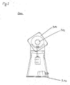
- the one shown in Fig. 2 and with the magazine bar 100 corresponding Clip coil holder 200 is for example for mounting on the housing top a closing device suitable. He has a base 210, with which he be flanged to an upper housing surface of the closing device can. At its upper, the base opposite end, he has a Axis 212 on. On this axis 212, a spool receptacle 214 is rotatable stored.
- Fig. 5 an arrangement in plan view is shown, which recognize leaves that in a symmetrical embodiment of the clip coil holder 200 two Clip spools 512, 513 from opposite sides to corresponding ones Receivers 214 can be attached axially. These coils are going through Springs 514 against accidental slipping off the spool seats secured.
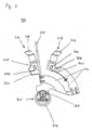
- the pair 300 of coupled drive elements 310, 312 shown in FIG consists of those drive elements 310, 312, each with not here have shown clip strand engageable engagement surfaces 311, 313, and a common arm 314, on which both drive elements 310, 312 are attached.
- the drive elements are in Engaging area forked so that they surround the inner guide rail 112 and can engage symmetrically on the clip strand 510.
- the engagement surfaces can be jagged, roughened or gummed, so either a rubbing or a positive entrainment of the clip strand comes into consideration.
- the drive elements 310, 312 are opposite the engagement surfaces Bearings 318 and 320 for attachment to the arm 314, both a Pivoting movement of the drive elements as well as a linear independent thereof Allow movement of the drive elements in the radial direction.
- the drive elements also have at their engagement surfaces each have a curve 326, 328 opposite end.
- Two springs 322, 324 are applied to these curves.
- the curves are shaped so that the springs exert a moment on the drive elements 310, 312 by their spring force, which these in their rest position in an upright (not weggeschwenkte) Position forces.
- An unillustrated stop ensures that this position can not be exceeded and thus given a reverse direction becomes.
- the drive elements against the spring force are pivoted away. They therefore act like pawls. by virtue of the mirror-symmetrical structure corresponds to the freewheeling direction of the one Locking direction of the other pawl of the same pair 300.
- the springs 322, 324 also cause the drive elements 310, 312 radially be pressed against the outside of the clip strand, cf. Fig. 6. You ask thus within the scope of the linear movement enabled by the bearings 138, 320 a length or tolerance compensation safe and ensure at the same time for the needed pressure against the clips to ensure a safe feed guarantee.
- the arm 314 connects the drive elements 310, 312 with a hub 315, the itself from an axle-fixed part 316 and a radially movable part 317 composed and their pivot axis to the engagement surfaces 311, 313 both Drive elements is substantially equally spaced.
- the Pivot axis falls as shown in Figs. 5 to 8 can be seen in the here shown Embodiment with the axis 212 of the coil receiving 214 and the Rotation axis of the magazine bar receptacle 122 together. That turns out This advantage will be apparent from the reference to FIGS. 6 to 8 successful functional description can be seen.
- the radially movable part 317 which is connected to the arm 314, is in one too the axis fixed 316 part spaced, shown in extended position the drive elements 310, 312 abut the clip strand.
- the radial movable part 317 can - for example, by a pneumatic drive operated either manually or automatically - to the axle-fixed part 316 and be driven away again. As a result, the drive elements of this Couple together radially extended or extended and with the clip strand in or disengaged.
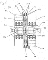
- Fig. 4 is an arrangement of two pairs of coupled drive elements 300 and 400 shown in plan view. These are aligned coaxially with each other, i. that the pivot axes 440 of their hubs together fall. They are also constructed in an identical way, but reversed so arranged against each other, that the drive elements 310, 312 and 410, 412 in two parallel planes perpendicular to the pivot axis 440 side by side lie. In other words, the drive elements 310 and 410 and 312 and 412 each in the same plane, i. on the same clip strand.
- the Double level arrangement makes the clip drive 450 shown here suitable for the use in a so-called. Double Clip Feeder 500.
- a wound on a bobbin 512, 513 clip strand is after unwound down and over each an associated pulley 516 or 518 the input 130 of the respectively associated magazine bar 100, as in Fig. 6 is illustrated supplied.
- the pulleys 516, 518 are tapered in Direction to the midplane tapered between the clip feeders, so that the clip strand 511 when unwinding in the axial direction to the respective Magazine bar 110 is steered.
- the two pairs of coupled drive elements 300 and 400 are located in the representation shown in Fig. 6 respectively in an end position of their Pivoting movement, in which the respective upper drive element 312 or 410 am Entrance area and thus arrived at the beginning of his feed path
- Double clip feeder 500 (not shown) position limit switch is provided.
- This associated with each feed path a total of two Position limit switches can be coupled by both pairs of drive elements For example, from a section, a cam or a projection of the respective arm 314 or the associated hub 315 are actuated.
- the Both position limit switches are preferably via a common Control connected to both drives, so that always the first operated Position limit switch triggers the direction reversal of all drive elements.
- the change between the blocking and freewheeling property of the drive elements is not mandatory, but can be replaced with a Direction reversal of the rotary actuator connected, active radial input and output Extensibility to be replaced.
- the pivoting of the Drive elements around their bearings 318, 320 mandatory, so that the both acting on the same clip strand drive elements 310 and 410 or 312 and 412 can escape in the manner shown in Fig. 7.
- Fig. 6 can still be seen that the feed path of the drive elements almost the complete semicircular portion 120 of the magazine bar 100 includes.
- the manually operated switch is therefore with the or the position limit switch (s) connected via a controller, so that the Pressing any of these switches reverses the direction of all Drive elements triggers.
- the switching reaches the second Drive element (active or passive) in engagement with the beginning of the new Clipstranges, the end of the old Clipstring pushes in front of him. A complete supply of clips can be so in the ongoing operation without downtime to be ensured.
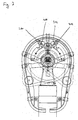
- Fig. 7 the drive elements are seen in a different position. you are designed so that the currently disengaged drive element 410, 312 when it is in engagement on the same strand of clips Drive element 310 or 412 passively passes around its respective bearing 318, 320 is pivoted away against the spring force. Also in place of these advantageous Continuing can occur another construction. For example, the Feed paths both acting on the same clip strand drive elements be completely separated so that there can be no such encounter. Also under In these circumstances, a double-clip guide with only two (swivel) drives could be used realize, but at the price of a less compact design.
- FIG. 8 shows the same embodiment of the clip feed according to the invention, in this illustration, one of the two magazine bars 100 after solve the Lock 125 is pivoted away in such a way that the mouth to the corresponding separation window provided output 128 to this Separation window is spaced.
- This Wegschwenkvorgang serves the Purpose of access to the separator window and the clip mechanism of Capper. This can e.g. in case of malfunctions jammed or dammed locking clips in their feed channel behind the singulation window will be required. It is advantageous that through the pivoting movement of the magazine bar around its receptacle 123 the entire Magazine bar continues to remain attached to the clip feeder while it has been required in the area of its output to the housing of the Closing device flanged magazine bar completely from the Remove the closing device.
Landscapes
- Life Sciences & Earth Sciences (AREA)
- Engineering & Computer Science (AREA)
- Wood Science & Technology (AREA)
- Zoology (AREA)
- Food Science & Technology (AREA)
- Basic Packing Technique (AREA)
- Package Closures (AREA)
- Lead Frames For Integrated Circuits (AREA)
- Container, Conveyance, Adherence, Positioning, Of Wafer (AREA)
- Surgical Instruments (AREA)
- Electric Cable Installation (AREA)
- Dovetailed Work, And Nailing Machines And Stapling Machines For Wood (AREA)
Abstract
Description
- Fig. 1
- ein Ausführungsbeispiel einer Magazinstange der erfindungsgemäßen Clipzuführung in der Seitenansicht;
- Fig. 2
- einen Clipspulenhalter gemäß einer Ausführungsform der erfindungsgemäßen Clipzuführung in der Seitenansicht;
- Fig. 3
- eine Seitenansicht eines Paares gekoppelter Antriebselemente gemäß demselben Ausführungsbeispiel der erfindungsgemäßen Clipzuführung;
- Fig. 4
- zwei Paare gekoppelter Antriebselemente in der Draufsicht;
- Fig. 5
- eine Teilansicht des Ausführungsbeispiels der erfindungsgemäßen Clipzuführung von oben;
- Fig. 6
- das Ausführungsbeispiel der erfindungsgemäßen Clipzuführung aus Fig. 5 in der totalen Seitenansicht mit den zwei Paaren gekoppelter Antriebselemente in einer ersten Endstellung;
- Fig. 7
- dieselbe Ansicht des Ausführungsbeispiels der Clipzuführung mit den zwei Paaren gekoppelter Antriebselemente in einer sich kreuzenden Stellung; und
- Fig. 8
- die Seitensicht auf die erfindungsgemäße Clipzuführung mit einer weggeschwenkten Magazinstange.
Claims (9)
- Magazinstange mit einem Eingang und einem Ausgang zum Führen eines Clipstranges von einem oberhalb eines Vereinzelungsfensters einer Verschließvorrichtung angeordneten Clipvorrat zu dem im Wesentlichen vertikal angeordneten Vereinzelungsfenster,
dadurch gekennzeichnet, dass die Magazinstange eine erste Umlenkung aufweist, dergestalt dass der Clipsstrang von unten in den Eingang zuführbar ist. - Magazinstange nach Anspruch 1,
gekennzeichnet durch einen stromabwärts hinter der ersten Umlenkung befindlichen Abschnitt, auf dem der Clipstrang nach unten führbar ist, und eine weiter stromabwärts befindliche zweite Umlenkung, dergestalt dass die Magazinstange im Wesentlichen horizontal in ihren Ausgang mündet. - Magazinstange nach Anspruch 2,
dadurch gekennzeichnet, dass die erste Umlenkung durch einen in etwa halbkreisförmigen Abschnitt der Magazinstange gebildet wird. - Magazinstange nach Anspruch 3,
dadurch gekennzeichnet, dass die Magazinstange mittels einer Aufnahme um eine durch den halbkreisförmigen Abschnitt bestimmte Rotationsachse schwenkbar ist. - Clipzuführung mit einem Halter für eine den Clipvorrat bereithaltende Spule,
gekennzeichnet durch eine Magazinstange nach einem der Ansprüche 1 bis 4. - Clipzuführung nach Anspruch 5 in Verbindung mit Anspruch 4,
dadurch gekennzeichnet, dass der Halter eine Axialaufnahme für die Spule aufweist und dass die Rotationsachse der Magazinstange mit der Achse der Axialaufnahme zusammenfällt. - Clipzuführung nach Anspruch 6,
dadurch gekennzeichnet, dass der Radius des halbkreisförmigen Abschnitts im Wesentlichen dem Radius der Spule gleicht. - Clipzuführung nach einem der Ansprüche 5 bis 7,
dadurch gekennzeichnet, dass zwischen dem Clipvorrat und dem Eingang der Magazinstange eine Umlenkrolle eingeschaltet ist. - Verschließvorrichtung zum Abteilen von Portionspackungen eines unterteilbaren Füllguts in einer flexiblen Schlauchhülle durch Einschnüren des gefüllten Schlauches und Aufbringen zweier Verschlusselemente auf den durch axiales Verdrängen des Füllgutes gebildeten Schlauchzopf, mit einer Clipzuführung nach einem der Ansprüche 5 bis 8.
Applications Claiming Priority (2)
| Application Number | Priority Date | Filing Date | Title |
|---|---|---|---|
| DE102004010392 | 2004-03-03 | ||
| DE102004010392A DE102004010392B3 (de) | 2004-03-03 | 2004-03-03 | Magazinstange |
Publications (2)
| Publication Number | Publication Date |
|---|---|
| EP1571090A1 true EP1571090A1 (de) | 2005-09-07 |
| EP1571090B1 EP1571090B1 (de) | 2006-11-08 |
Family
ID=34745367
Family Applications (1)
| Application Number | Title | Priority Date | Filing Date |
|---|---|---|---|
| EP05004724A Expired - Lifetime EP1571090B1 (de) | 2004-03-03 | 2005-03-03 | Magazinstange |
Country Status (4)
| Country | Link |
|---|---|
| EP (1) | EP1571090B1 (de) |
| AT (1) | ATE344760T1 (de) |
| DE (2) | DE102004010392B3 (de) |
| ES (1) | ES2276361T3 (de) |
Cited By (1)
| Publication number | Priority date | Publication date | Assignee | Title |
|---|---|---|---|---|
| EP2294921A1 (de) * | 2009-09-11 | 2011-03-16 | Poly-clip System GmbH & Co. KG | Magazinstange mit Ladestelle |
Families Citing this family (1)
| Publication number | Priority date | Publication date | Assignee | Title |
|---|---|---|---|---|
| DE102008020046B4 (de) | 2008-04-22 | 2012-09-06 | J+P Maschinenbau Gmbh | Einrichtung zum Führen eines Clipbandes |
Citations (3)
| Publication number | Priority date | Publication date | Assignee | Title |
|---|---|---|---|---|
| US4571805A (en) * | 1983-09-20 | 1986-02-25 | Herbert Niedecker | Apparatus for closing tubular wrappers with U-shaped closing clips |
| US4675945A (en) * | 1985-01-23 | 1987-06-30 | Tipper Tie, Inc. | Clipping apparatus |
| US5586424A (en) * | 1992-05-15 | 1996-12-24 | Delaware Capital Formation, Inc. | Apparatus for movement of U-shaped clips along a rail |
Family Cites Families (1)
| Publication number | Priority date | Publication date | Assignee | Title |
|---|---|---|---|---|
| US3189220A (en) * | 1962-05-09 | 1965-06-15 | Fastener Corp | Fastener feed construction |
-
2004
- 2004-03-03 DE DE102004010392A patent/DE102004010392B3/de not_active Expired - Fee Related
-
2005
- 2005-03-03 ES ES05004724T patent/ES2276361T3/es not_active Expired - Lifetime
- 2005-03-03 EP EP05004724A patent/EP1571090B1/de not_active Expired - Lifetime
- 2005-03-03 AT AT05004724T patent/ATE344760T1/de not_active IP Right Cessation
- 2005-03-03 DE DE502005000165T patent/DE502005000165D1/de not_active Expired - Lifetime
Patent Citations (3)
| Publication number | Priority date | Publication date | Assignee | Title |
|---|---|---|---|---|
| US4571805A (en) * | 1983-09-20 | 1986-02-25 | Herbert Niedecker | Apparatus for closing tubular wrappers with U-shaped closing clips |
| US4675945A (en) * | 1985-01-23 | 1987-06-30 | Tipper Tie, Inc. | Clipping apparatus |
| US5586424A (en) * | 1992-05-15 | 1996-12-24 | Delaware Capital Formation, Inc. | Apparatus for movement of U-shaped clips along a rail |
Cited By (1)
| Publication number | Priority date | Publication date | Assignee | Title |
|---|---|---|---|---|
| EP2294921A1 (de) * | 2009-09-11 | 2011-03-16 | Poly-clip System GmbH & Co. KG | Magazinstange mit Ladestelle |
Also Published As
| Publication number | Publication date |
|---|---|
| DE502005000165D1 (de) | 2006-12-21 |
| ATE344760T1 (de) | 2006-11-15 |
| EP1571090B1 (de) | 2006-11-08 |
| ES2276361T3 (es) | 2007-06-16 |
| DE102004010392B3 (de) | 2005-08-25 |
Similar Documents
| Publication | Publication Date | Title |
|---|---|---|
| DE2341328C3 (de) | Rolltor | |
| DE2352157C3 (de) | Bindevorrichtung zum Umbinden von Bündeln mit Bindedraht | |
| DE69120123T2 (de) | Schlauchbandförderer | |
| DE102008057806A1 (de) | Rundmagazin für eine Spulstelle eines Kreuzspulautomaten | |
| DE644171C (de) | Foerdervorrichtung mit einem aus elastischem Material, insbesondere Gummi, bestehenden endlosen Foerderrohr | |
| DE3335964C2 (de) | ||
| EP1570741B1 (de) | Clipzuführung | |
| DE2610084C2 (de) | Verfahren und Vorrichtung zum Wickeln konischer Kreuzspulen | |
| DE1200239B (de) | Drahtwickler | |
| EP1571090B1 (de) | Magazinstange | |
| DE1901638B2 (de) | Vorrichtung zum automatischen auswechseln voller spulen gegen leere spulenhuelsen fuer ringspinn- und ringzwirnmaschinen | |
| EP1571089B1 (de) | Clipzuführung | |
| DE3407804A1 (de) | Spulentransportvorrichtung | |
| CH623014A5 (de) | ||
| DE2643434A1 (de) | Spulenwechselvorrichtung mit einer automatischen trennvorrichtung zum trennen des spulfadens oder bandes | |
| EP3168341B1 (de) | Spannvorrichtung für einen antriebsriemen von spindeln einer spinnmaschine | |
| DE2805290C2 (de) | Vorrichtung zur Überführung von Flaschen | |
| DE882208C (de) | Vorrichtung zum Aufwickeln von Faserbaendern an Textilmaschinen | |
| DE3121691C2 (de) | Nach Art eines Flaschenzuges ausgebildeter Zwischenspeicher in Verbindung mit einer Aufwickelvorrichtung für strangförmiges Gut | |
| DE2257944C2 (de) | Vorrichtung zum fortlaufenden Aufwickeln von fadenförmigem Gut | |
| DE2346572C3 (de) | Vorrichtung zum Fördern und Verteilen von Heu u.dgl | |
| DE2542222B2 (de) | Kopsabziehvorrichtung für Spinn- und Zwirnmaschinen | |
| DE3925651C2 (de) | ||
| DE1510654C2 (de) | Vorrichtung zum Aufbringen einer Fadenreserve | |
| EP1547476B1 (de) | Transport eines Hüllstreifens der Tabak verarbeitenden Industrie |
Legal Events
| Date | Code | Title | Description |
|---|---|---|---|
| PUAI | Public reference made under article 153(3) epc to a published international application that has entered the european phase |
Free format text: ORIGINAL CODE: 0009012 |
|
| AK | Designated contracting states |
Kind code of ref document: A1 Designated state(s): AT BE BG CH CY CZ DE DK EE ES FI FR GB GR HU IE IS IT LI LT LU MC NL PL PT RO SE SI SK TR |
|
| AX | Request for extension of the european patent |
Extension state: AL BA HR LV MK YU |
|
| 17P | Request for examination filed |
Effective date: 20060307 |
|
| GRAP | Despatch of communication of intention to grant a patent |
Free format text: ORIGINAL CODE: EPIDOSNIGR1 |
|
| AKX | Designation fees paid |
Designated state(s): AT BE BG CH CY CZ DE DK EE ES FI FR GB GR HU IE IS IT LI LT LU MC NL PL PT RO SE SI SK TR |
|
| GRAS | Grant fee paid |
Free format text: ORIGINAL CODE: EPIDOSNIGR3 |
|
| GRAA | (expected) grant |
Free format text: ORIGINAL CODE: 0009210 |
|
| AK | Designated contracting states |
Kind code of ref document: B1 Designated state(s): AT BE BG CH CY CZ DE DK EE ES FI FR GB GR HU IE IS IT LI LT LU MC NL PL PT RO SE SI SK TR |
|
| PG25 | Lapsed in a contracting state [announced via postgrant information from national office to epo] |
Ref country code: CZ Free format text: LAPSE BECAUSE OF FAILURE TO SUBMIT A TRANSLATION OF THE DESCRIPTION OR TO PAY THE FEE WITHIN THE PRESCRIBED TIME-LIMIT Effective date: 20061108 Ref country code: PL Free format text: LAPSE BECAUSE OF FAILURE TO SUBMIT A TRANSLATION OF THE DESCRIPTION OR TO PAY THE FEE WITHIN THE PRESCRIBED TIME-LIMIT Effective date: 20061108 Ref country code: IE Free format text: LAPSE BECAUSE OF FAILURE TO SUBMIT A TRANSLATION OF THE DESCRIPTION OR TO PAY THE FEE WITHIN THE PRESCRIBED TIME-LIMIT Effective date: 20061108 Ref country code: RO Free format text: LAPSE BECAUSE OF FAILURE TO SUBMIT A TRANSLATION OF THE DESCRIPTION OR TO PAY THE FEE WITHIN THE PRESCRIBED TIME-LIMIT Effective date: 20061108 Ref country code: SI Free format text: LAPSE BECAUSE OF FAILURE TO SUBMIT A TRANSLATION OF THE DESCRIPTION OR TO PAY THE FEE WITHIN THE PRESCRIBED TIME-LIMIT Effective date: 20061108 Ref country code: FI Free format text: LAPSE BECAUSE OF FAILURE TO SUBMIT A TRANSLATION OF THE DESCRIPTION OR TO PAY THE FEE WITHIN THE PRESCRIBED TIME-LIMIT Effective date: 20061108 Ref country code: SK Free format text: LAPSE BECAUSE OF FAILURE TO SUBMIT A TRANSLATION OF THE DESCRIPTION OR TO PAY THE FEE WITHIN THE PRESCRIBED TIME-LIMIT Effective date: 20061108 |
|
| REG | Reference to a national code |
Ref country code: GB Ref legal event code: FG4D Free format text: NOT ENGLISH |
|
| REG | Reference to a national code |
Ref country code: CH Ref legal event code: EP |
|
| REG | Reference to a national code |
Ref country code: IE Ref legal event code: FG4D Free format text: LANGUAGE OF EP DOCUMENT: GERMAN |
|
| REG | Reference to a national code |
Ref country code: CH Ref legal event code: NV Representative=s name: ZIMMERLI, WAGNER & PARTNER AG |
|
| REF | Corresponds to: |
Ref document number: 502005000165 Country of ref document: DE Date of ref document: 20061221 Kind code of ref document: P |
|
| PG25 | Lapsed in a contracting state [announced via postgrant information from national office to epo] |
Ref country code: SE Free format text: LAPSE BECAUSE OF FAILURE TO SUBMIT A TRANSLATION OF THE DESCRIPTION OR TO PAY THE FEE WITHIN THE PRESCRIBED TIME-LIMIT Effective date: 20070208 Ref country code: DK Free format text: LAPSE BECAUSE OF FAILURE TO SUBMIT A TRANSLATION OF THE DESCRIPTION OR TO PAY THE FEE WITHIN THE PRESCRIBED TIME-LIMIT Effective date: 20070208 Ref country code: BG Free format text: LAPSE BECAUSE OF FAILURE TO SUBMIT A TRANSLATION OF THE DESCRIPTION OR TO PAY THE FEE WITHIN THE PRESCRIBED TIME-LIMIT Effective date: 20070208 |
|
| PG25 | Lapsed in a contracting state [announced via postgrant information from national office to epo] |
Ref country code: IS Free format text: LAPSE BECAUSE OF FAILURE TO SUBMIT A TRANSLATION OF THE DESCRIPTION OR TO PAY THE FEE WITHIN THE PRESCRIBED TIME-LIMIT Effective date: 20070308 |
|
| PG25 | Lapsed in a contracting state [announced via postgrant information from national office to epo] |
Ref country code: PT Free format text: LAPSE BECAUSE OF FAILURE TO SUBMIT A TRANSLATION OF THE DESCRIPTION OR TO PAY THE FEE WITHIN THE PRESCRIBED TIME-LIMIT Effective date: 20070409 |
|
| GBV | Gb: ep patent (uk) treated as always having been void in accordance with gb section 77(7)/1977 [no translation filed] |
Effective date: 20061108 |
|
| ET | Fr: translation filed | ||
| REG | Reference to a national code |
Ref country code: ES Ref legal event code: FG2A Ref document number: 2276361 Country of ref document: ES Kind code of ref document: T3 |
|
| REG | Reference to a national code |
Ref country code: IE Ref legal event code: FD4D |
|
| PLBE | No opposition filed within time limit |
Free format text: ORIGINAL CODE: 0009261 |
|
| STAA | Information on the status of an ep patent application or granted ep patent |
Free format text: STATUS: NO OPPOSITION FILED WITHIN TIME LIMIT |
|
| 26N | No opposition filed |
Effective date: 20070809 |
|
| PG25 | Lapsed in a contracting state [announced via postgrant information from national office to epo] |
Ref country code: GB Free format text: LAPSE BECAUSE OF FAILURE TO SUBMIT A TRANSLATION OF THE DESCRIPTION OR TO PAY THE FEE WITHIN THE PRESCRIBED TIME-LIMIT Effective date: 20061108 |
|
| BERE | Be: lapsed |
Owner name: POLY-CLIP SYSTEM G.M.B.H. & CO. KG Effective date: 20070331 |
|
| PG25 | Lapsed in a contracting state [announced via postgrant information from national office to epo] |
Ref country code: BE Free format text: LAPSE BECAUSE OF NON-PAYMENT OF DUE FEES Effective date: 20070331 |
|
| PG25 | Lapsed in a contracting state [announced via postgrant information from national office to epo] |
Ref country code: MC Free format text: LAPSE BECAUSE OF NON-PAYMENT OF DUE FEES Effective date: 20070331 |
|
| PG25 | Lapsed in a contracting state [announced via postgrant information from national office to epo] |
Ref country code: GR Free format text: LAPSE BECAUSE OF FAILURE TO SUBMIT A TRANSLATION OF THE DESCRIPTION OR TO PAY THE FEE WITHIN THE PRESCRIBED TIME-LIMIT Effective date: 20070209 |
|
| PGFP | Annual fee paid to national office [announced via postgrant information from national office to epo] |
Ref country code: FR Payment date: 20070321 Year of fee payment: 3 |
|
| PG25 | Lapsed in a contracting state [announced via postgrant information from national office to epo] |
Ref country code: AT Free format text: LAPSE BECAUSE OF NON-PAYMENT OF DUE FEES Effective date: 20070303 |
|
| PG25 | Lapsed in a contracting state [announced via postgrant information from national office to epo] |
Ref country code: LT Free format text: LAPSE BECAUSE OF FAILURE TO SUBMIT A TRANSLATION OF THE DESCRIPTION OR TO PAY THE FEE WITHIN THE PRESCRIBED TIME-LIMIT Effective date: 20061108 |
|
| REG | Reference to a national code |
Ref country code: FR Ref legal event code: ST Effective date: 20081125 |
|
| PG25 | Lapsed in a contracting state [announced via postgrant information from national office to epo] |
Ref country code: EE Free format text: LAPSE BECAUSE OF FAILURE TO SUBMIT A TRANSLATION OF THE DESCRIPTION OR TO PAY THE FEE WITHIN THE PRESCRIBED TIME-LIMIT Effective date: 20061108 |
|
| PG25 | Lapsed in a contracting state [announced via postgrant information from national office to epo] |
Ref country code: FR Free format text: LAPSE BECAUSE OF NON-PAYMENT OF DUE FEES Effective date: 20080331 |
|
| PG25 | Lapsed in a contracting state [announced via postgrant information from national office to epo] |
Ref country code: LU Free format text: LAPSE BECAUSE OF NON-PAYMENT OF DUE FEES Effective date: 20070303 Ref country code: CY Free format text: LAPSE BECAUSE OF FAILURE TO SUBMIT A TRANSLATION OF THE DESCRIPTION OR TO PAY THE FEE WITHIN THE PRESCRIBED TIME-LIMIT Effective date: 20061108 |
|
| PG25 | Lapsed in a contracting state [announced via postgrant information from national office to epo] |
Ref country code: TR Free format text: LAPSE BECAUSE OF FAILURE TO SUBMIT A TRANSLATION OF THE DESCRIPTION OR TO PAY THE FEE WITHIN THE PRESCRIBED TIME-LIMIT Effective date: 20061108 Ref country code: HU Free format text: LAPSE BECAUSE OF FAILURE TO SUBMIT A TRANSLATION OF THE DESCRIPTION OR TO PAY THE FEE WITHIN THE PRESCRIBED TIME-LIMIT Effective date: 20070509 |
|
| REG | Reference to a national code |
Ref country code: CH Ref legal event code: PFA Owner name: POLY-CLIP SYSTEM GMBH & CO. KG Free format text: POLY-CLIP SYSTEM GMBH & CO. KG#WESTERBACHSTRASSE 45#60489 FRANKFURT AM MAIN (DE) -TRANSFER TO- POLY-CLIP SYSTEM GMBH & CO. KG#WESTERBACHSTRASSE 45#60489 FRANKFURT AM MAIN (DE) |
|
| REG | Reference to a national code |
Ref country code: CH Ref legal event code: PFA Owner name: POLY-CLIP SYSTEM GMBH & CO. KG Free format text: POLY-CLIP SYSTEM GMBH & CO. KG#WESTERBACHSTRASSE 45#60489 FRANKFURT AM MAIN (DE) -TRANSFER TO- POLY-CLIP SYSTEM GMBH & CO. KG#NIEDECKERSTRASSE 1#65795 HATTERSHEIM (DE) |
|
| REG | Reference to a national code |
Ref country code: DE Ref legal event code: R082 Ref document number: 502005000165 Country of ref document: DE Representative=s name: EISENFUEHR, SPEISER & PARTNER, DE |
|
| REG | Reference to a national code |
Ref country code: DE Ref legal event code: R081 Ref document number: 502005000165 Country of ref document: DE Owner name: POLY-CLIP SYSTEM GMBH & CO. KG, DE Free format text: FORMER OWNER: POLY-CLIP SYSTEM GMBH & CO. KG, 60489 FRANKFURT, DE Effective date: 20130827 Ref country code: DE Ref legal event code: R082 Ref document number: 502005000165 Country of ref document: DE Representative=s name: EISENFUEHR SPEISER PATENTANWAELTE RECHTSANWAEL, DE Effective date: 20130827 |
|
| REG | Reference to a national code |
Ref country code: CH Ref legal event code: NV Representative=s name: WAGNER PATENT AG, CH |
|
| PGFP | Annual fee paid to national office [announced via postgrant information from national office to epo] |
Ref country code: NL Payment date: 20140320 Year of fee payment: 10 |
|
| PGFP | Annual fee paid to national office [announced via postgrant information from national office to epo] |
Ref country code: ES Payment date: 20140324 Year of fee payment: 10 Ref country code: IT Payment date: 20140328 Year of fee payment: 10 |
|
| PGFP | Annual fee paid to national office [announced via postgrant information from national office to epo] |
Ref country code: CH Payment date: 20150325 Year of fee payment: 11 |
|
| REG | Reference to a national code |
Ref country code: NL Ref legal event code: MM Effective date: 20150401 |
|
| PG25 | Lapsed in a contracting state [announced via postgrant information from national office to epo] |
Ref country code: IT Free format text: LAPSE BECAUSE OF NON-PAYMENT OF DUE FEES Effective date: 20150303 |
|
| REG | Reference to a national code |
Ref country code: ES Ref legal event code: FD2A Effective date: 20160527 |
|
| PG25 | Lapsed in a contracting state [announced via postgrant information from national office to epo] |
Ref country code: ES Free format text: LAPSE BECAUSE OF NON-PAYMENT OF DUE FEES Effective date: 20150304 |
|
| REG | Reference to a national code |
Ref country code: CH Ref legal event code: PL |
|
| PG25 | Lapsed in a contracting state [announced via postgrant information from national office to epo] |
Ref country code: LI Free format text: LAPSE BECAUSE OF NON-PAYMENT OF DUE FEES Effective date: 20160331 Ref country code: CH Free format text: LAPSE BECAUSE OF NON-PAYMENT OF DUE FEES Effective date: 20160331 |
|
| PG25 | Lapsed in a contracting state [announced via postgrant information from national office to epo] |
Ref country code: NL Free format text: LAPSE BECAUSE OF NON-PAYMENT OF DUE FEES Effective date: 20150401 |
|
| PGFP | Annual fee paid to national office [announced via postgrant information from national office to epo] |
Ref country code: DE Payment date: 20190404 Year of fee payment: 15 |
|
| REG | Reference to a national code |
Ref country code: DE Ref legal event code: R119 Ref document number: 502005000165 Country of ref document: DE |
|
| PG25 | Lapsed in a contracting state [announced via postgrant information from national office to epo] |
Ref country code: DE Free format text: LAPSE BECAUSE OF NON-PAYMENT OF DUE FEES Effective date: 20201001 |