EP1570996B1 - Tintenstrahlaufzeichnungsgerät - Google Patents
Tintenstrahlaufzeichnungsgerät Download PDFInfo
- Publication number
- EP1570996B1 EP1570996B1 EP05004680A EP05004680A EP1570996B1 EP 1570996 B1 EP1570996 B1 EP 1570996B1 EP 05004680 A EP05004680 A EP 05004680A EP 05004680 A EP05004680 A EP 05004680A EP 1570996 B1 EP1570996 B1 EP 1570996B1
- Authority
- EP
- European Patent Office
- Prior art keywords
- ink
- air
- ink cartridge
- port
- mounting portion
- Prior art date
- Legal status (The legal status is an assumption and is not a legal conclusion. Google has not performed a legal analysis and makes no representation as to the accuracy of the status listed.)
- Expired - Lifetime
Links
- 238000007789 sealing Methods 0.000 claims description 14
- 239000011148 porous material Substances 0.000 claims description 7
- 239000013013 elastic material Substances 0.000 claims description 4
- 239000000976 ink Substances 0.000 description 219
- 238000010926 purge Methods 0.000 description 9
- 230000008020 evaporation Effects 0.000 description 8
- 238000001704 evaporation Methods 0.000 description 8
- 230000000694 effects Effects 0.000 description 4
- 229920005989 resin Polymers 0.000 description 4
- 239000011347 resin Substances 0.000 description 4
- 239000002699 waste material Substances 0.000 description 4
- 239000000463 material Substances 0.000 description 3
- 230000002829 reductive effect Effects 0.000 description 3
- 238000004519 manufacturing process Methods 0.000 description 2
- XLYOFNOQVPJJNP-UHFFFAOYSA-N water Substances O XLYOFNOQVPJJNP-UHFFFAOYSA-N 0.000 description 2
- 230000008859 change Effects 0.000 description 1
- 239000003086 colorant Substances 0.000 description 1
- 230000006835 compression Effects 0.000 description 1
- 238000007906 compression Methods 0.000 description 1
- 238000005520 cutting process Methods 0.000 description 1
- 230000003247 decreasing effect Effects 0.000 description 1
- 239000012530 fluid Substances 0.000 description 1
- 230000002401 inhibitory effect Effects 0.000 description 1
- 230000007246 mechanism Effects 0.000 description 1
- 230000004048 modification Effects 0.000 description 1
- 238000012986 modification Methods 0.000 description 1
- 230000002441 reversible effect Effects 0.000 description 1
- 229920003002 synthetic resin Polymers 0.000 description 1
- 239000000057 synthetic resin Substances 0.000 description 1
- 238000003466 welding Methods 0.000 description 1
Images


Classifications
-
- B—PERFORMING OPERATIONS; TRANSPORTING
- B41—PRINTING; LINING MACHINES; TYPEWRITERS; STAMPS
- B41J—TYPEWRITERS; SELECTIVE PRINTING MECHANISMS, i.e. MECHANISMS PRINTING OTHERWISE THAN FROM A FORME; CORRECTION OF TYPOGRAPHICAL ERRORS
- B41J2/00—Typewriters or selective printing mechanisms characterised by the printing or marking process for which they are designed
- B41J2/005—Typewriters or selective printing mechanisms characterised by the printing or marking process for which they are designed characterised by bringing liquid or particles selectively into contact with a printing material
- B41J2/01—Ink jet
- B41J2/17—Ink jet characterised by ink handling
- B41J2/175—Ink supply systems ; Circuit parts therefor
- B41J2/17503—Ink cartridges
- B41J2/17513—Inner structure
-
- B—PERFORMING OPERATIONS; TRANSPORTING
- B41—PRINTING; LINING MACHINES; TYPEWRITERS; STAMPS
- B41J—TYPEWRITERS; SELECTIVE PRINTING MECHANISMS, i.e. MECHANISMS PRINTING OTHERWISE THAN FROM A FORME; CORRECTION OF TYPOGRAPHICAL ERRORS
- B41J2/00—Typewriters or selective printing mechanisms characterised by the printing or marking process for which they are designed
- B41J2/005—Typewriters or selective printing mechanisms characterised by the printing or marking process for which they are designed characterised by bringing liquid or particles selectively into contact with a printing material
- B41J2/01—Ink jet
- B41J2/17—Ink jet characterised by ink handling
- B41J2/175—Ink supply systems ; Circuit parts therefor
- B41J2/17503—Ink cartridges
- B41J2/1752—Mounting within the printer
- B41J2/17523—Ink connection
-
- B—PERFORMING OPERATIONS; TRANSPORTING
- B41—PRINTING; LINING MACHINES; TYPEWRITERS; STAMPS
- B41J—TYPEWRITERS; SELECTIVE PRINTING MECHANISMS, i.e. MECHANISMS PRINTING OTHERWISE THAN FROM A FORME; CORRECTION OF TYPOGRAPHICAL ERRORS
- B41J2/00—Typewriters or selective printing mechanisms characterised by the printing or marking process for which they are designed
- B41J2/005—Typewriters or selective printing mechanisms characterised by the printing or marking process for which they are designed characterised by bringing liquid or particles selectively into contact with a printing material
- B41J2/01—Ink jet
- B41J2/17—Ink jet characterised by ink handling
- B41J2/175—Ink supply systems ; Circuit parts therefor
- B41J2/17503—Ink cartridges
- B41J2/17553—Outer structure
Definitions
- the invention relates to an inkjet recording apparatus, and particularly to an inkjet recording apparatus having a fluid passage through which air is supplied into an ink cartridge as mounted on the inkjet recording apparatus.
- JP-A-9-207347 corresponding to U.S. Patent No. 5,992,988 , there is known an inkjet recording apparatus where a labyrinthine air communication passage in communication with an air communication port is formed in an ink cartridge to restrict flow of air into and out of the ink cartridge through the air communication port in order to prevent evaporation of ink or water in the ink.
- JP-A-9-85963 corresponding to U.S. Patents Nos. 6,010,213 and 6,450,630 is disclosed another arrangement where an ink container (or an ink cartridge) is detachably attached to a holder (or a mounting portion).
- a holder or a mounting portion
- an air communication passage in which an ink-attracting porous material is accommodated, and an ink supply passage connected to a recording head.
- Two openings in the ink cartridge are connected to these passages, respectively.
- JP-A-9-85963 where upon mounting of the ink cartridge the porous material in the air communication passage absorbs the ink to make the pressure inside the ink cartridge negative, evaporation of the ink at the air communication passage and a variation in compression of the porous material make the negative pressure in the ink cartridge unstable.
- connection unit for connecting a cartridge to the recording apparatus.
- the connection unit has a recessed portion provided in a wall thereof.
- the recessed portion is arranged to receive an air communication connection port of the cartridge.
- a capillary extends from this recess to provide a connection between the ink storing chamber of the cartridge and the outside air.
- the capillary shows at least three full turns and is provided in the connection unit 80.
- An object of the present invention is therefore to provide an inkjet recording apparatus having a labyrinthine air communication passage for supplying air into an ink cartridge, and capable of solving the above-described problems.
- this invention provides an inkjet recording apparatus which comprises a recording head which ejects ink droplets to perform recording, an ink cartridge, and a mounting portion on which the ink cartridge is detachably mountable.
- the ink cartridge has an ink chamber for storing ink, an ink supply port for supplying the ink to the recording head therethrough, and an air introducing port for introducing an atmospheric air into the ink chamber therethrough.
- the mounting portion has an ink supply portion for supplying the ink drawn from the ink cartridge to the recording head, and an air introduction portion for supplying the atmospheric air into the ink chamber.
- the air introduction portion comprises an air supply port disposed to positionally correspond to the air introducing port of the ink cartridge when the ink cartridge is mounted on the mounting portion, an air intake port for taking in the atmospheric air therethrough, and an air supply passage which extends between the air supply port and the air intake port and whose shape comprises a turn.
- the air supply portion comprises the air supply passage which includes the turn and connects the air intake port for taking in the atmospheric air therethrough with the air supply port disposed at a position corresponding to the air introducing port of the ink cartridge as mounted on the mounting portion.
- the air supply passage can be designed with more freedom with respect to the length and shape of the air supply passage, while the ink cartridge which is an expendable part can be produced at a reduced cost, making it possible to offer the ink cartridge at a lower price.
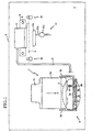
- FIG. 1 schematically shows an inkjet recording apparatus in which an ink cartridge according to the embodiment is mounted.
- the ink cartridge 1 is detachably attached to the inkjet recording apparatus 2 having a recording head 7 from which ink droplets are ejected.
- the ink cartridge 1 stores the ink to be supplied to the recording head 7.
- the ink cartridge 1 comprises a casing 1a of a hollow box open on its upper side, and a lid 1b hermetically sealing the open, upper side of the casing 1a.
- the ink to be supplied to the recording head 7 is stored in an ink chamber 16 (shown in Fig. 2 ) formed inside the casing 1a.
- a plurality of such ink cartridges 1, which are filled with inks of respective colors, namely, cyan, magenta, yellow, and black, are attached to the inkjet recording apparatus 2.
- the inkjet recording apparatus 2 comprises a main body, which has a stationary part in which a mounting portion 3, on which the ink cartridges 1 are detachably attached, is disposed, a tank 5 for storing inks supplied via ink supply pipes 4 extending from the respective ink cartridges 1, the recording head 7 for ejecting droplets of the inks stored in the tank 5 toward a recording sheet 6, a carriage 8 on which the tank 5 and the recording head 7 are mounted and which is horizontally reciprocated, a carriage rod 9 guiding the reciprocation of the carriage 8, a feeding mechanism for feeding the recording sheet 6, and a purge device 11.
- the mounting portion 3 comprises a base portion 3a, and a guide portion 3b comprising two segments each standing upright from one of opposite sides of the base portion 3a.
- ink drawing tubes 12 protruding from the base portion 3a for drawing the inks stored in the ink cartridges 1, and air supply ports 91 for supplying air to the inside of the ink cartridges 1.
- each ink drawing tube 12 communicates with an ink supply passage 94, and in turn with the tank 5 via the ink supply pipe 4.
- Each air supply port 91 is in communication with an air supply passage 92 and an air intake port 93, as shown in Fig. 5 .
- Each ink cartridge 1 is mounted on the mounting portion 3 in a vertical direction, namely, an X direction as indicated by an arrow in Fig. 1 .
- the ink drawing tube 12 opens a first valve device 23 (described later) disposed in the ink cartridge 1 to be brought into communication with the inside of the ink chamber 16.
- the air supply port 91 is also in communication with the inside of the ink chamber 16.
- the recording head 7 has a plurality of nozzles in its surface opposed to the recording sheet 6.
- an actuator comprising a piezoelectric element
- a droplet of a corresponding one of the inks stored in the tank 5 is ejected toward the recording sheet 6 through a corresponding one of the nozzles.
- Actual recording on the recording sheet 6 is performed while the carriage 8 is reciprocated with the recording head 7 thereon.
- the recording head 7 is disposed on the mounting portion 3, and the ink inside each nozzle is under negative pressure. That is, a head difference between each ink cartridge 1 as mounted on the mounting portion 3 and the nozzles applies a negative back pressure to the ink inside each nozzle.
- the purge device 11 is disposed outside a recording area and at a position to be opposed to the recording head 7.
- the purge device 11 comprises a purge cap 11a to cover the surface of the recording head 7 where the nozzles are formed, a waste ink tube 11b in communication with the purge cap 11a, and a pump 11c for sucking the ink from each nozzle via the waste ink tube 11b.
- the carriage 8 When a purge operation is performed, the carriage 8 is moved to a purge position, and the surface of the recording head 7 where the nozzles are formed are covered by the purge cap 11a. In this state, the pump 11c is driven to suck bad ink containing bubbles and/or others, which is accumulated inside the recording head 7. The sucked bad ink is stored in a waste ink tank not shown, via the waste ink tube 11b.
- the recording and purge operations are controlled by a CPU (not shown) which is incorporated in the inkjet recording apparatus 2.
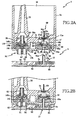
- Fig. 2A is a cross-sectional view of the joint portion "A" showing a state before the ink cartridge 1 is attached to the inkjet recording apparatus 2, while Fig, 2B shows a state after the ink cartridge 1 is attached.
- the ink cartridge 1 comprises the casing 1a defining inside the ink chamber 16 and open in its upper side, and the lid 1b covering the open upper side, and a cap member 1f covering a bottom wall of the casing 1a.
- the cap member 1f has two holes 1fa, 1fb through which the first valve device 23 and a second valve device 24, which will be described later, are exposed to the side of the mounting portion 3.
- the ink cartridge 1 is formed by welding the lid 1b and the cap member 1f to the casing 1a.
- the casing 1a, lid 1b and cap member 1f are made of a resin material.
- an ink supply port 21 open to supply the ink inside the ink chamber 16 to the outside.
- the ink supply port 21 is connected to a first communication chamber 30 formed inside a cylindrical wall 21a which extends from an undersurface of the bottom wall 1e and inside the bottom wall 1e.
- an air introducing port 26 which is open to the outside to introduce atmospheric air.
- the air introducing port 26 is connected to a second communication chamber 50 inside a cylindrical inner wall 26a formed to extend inside the bottom wall 1e from the undersurface of the bottom wall 1e.
- a check valve 60 which comprises a bevel elastic film portion 60b opposed to an underside of the ink supply port 21, and an axial portion 60c holding at its one end the bevel film portion 60b.
- the elastic film portion 60b and the axial portion 60c are integrally formed of a synthetic resin.
- the axial portion 60c is inserted through a hole formed in the bottom wall 1e, such that a vertical sliding movement of the axial portion 60c is permitted.
- the check valve 60 In an original state where the ink cartridge 1 is not mounted on the mounting portion 3, the check valve 60 is at a position such that the elastic film portion 60b thereof is separated from the ink supply port 21 with its bulging portion 60a held in contact with an upper surface of the bottom wall 1e, and therefore outflow of the ink from the ink chamber 16 toward the first valve device 23 is allowed.
- the film portion 60b When the ink cartridge 1 is mounted on the mounting portion 3 and if a flow of the ink from the ink drawing tube 12 toward the ink chamber 16 occurs, the film portion 60b is elevated to close the ink supply port 21 to inhibit this reverse ink flow.
- a tubular member 25 extends from the bottom wall 1e and inside the ink chamber 16, and defines therein an upper portion of the air introducing port 26, so that the air supplied from the outside is guided into an upper space in the ink chamber 16 through an internal passage or the upper portion of the air introducing port 26.
- An upper open end of the air introducing port 26 is located above the surface of the ink.
- the first valve device 23 as closure means is fixed to the first communication chamber 30 on an ink supply side.
- the second valve device 24 as closure means is fixed to the second communication chamber 50 on an air introduction side.
- the valve device 23 comprises an integrally formed support member 46 of a rubber or other elastic materials, and a valve member 32 of a resin material.
- the support member 46 is formed to have a generally cylindrical outer shape, and comprises a biasing portion 46b and a circular bottom wall portion 33 that are integrally formed.
- An upper surface of the circular bottom wall portion 33 is a valve seat surface 46a on which the valve member 32 is seated, and is positioned in an intermediate part of the support member 46 in an axial direction of the support member 46.
- the biasing portion 46b is on one side of the valve seat surface 46a near the ink chamber 16.
- the valve member 32 is accommodated in the biasing portion 46b and biased onto the valve seat surface 46a by the biasing portion 46b.
- the circular bottom wall portion 33 has an attaching portion 33a which radially outwardly extends, and the first communication chamber 30 has a stepped portion 44 having a larger diameter than the other portion thereof, so that the attaching portion 33a is fitted in the stepped portion 44.
- a protrusion 43 At a surface of the attaching portion 33a to be opposed to a shoulder of the stepped portion 44, there is formed a protrusion 43.
- the cap member 1f is fixed to the casing 1a while the attaching portion 33a is fitted between the shoulder of the stepped portion 44 and the cap member 1f such that the protrusion 43 is deformed by being pressed against the shoulder. This arrangement prevents leakage of the ink from between the circular bottom wall portion 33 of the valve device 23 and an inner wall of the first communication chamber 30.
- An opening 41 is formed at the center of the circular bottom wall portion 33 on the side of the valve seat surface 46a, while a guiding entrance 40, along which the ink drawing tube 12 is inserted, is formed at the center of the bottom wall portion 33 on the side opposite the valve seat surface 46a, such that the guiding entrance 40 and the opening 41 are in communication with each other.
- the guiding entrance 40 has, at its uppermost and most narrowed portion, a diameter smaller than an outer diameter of the ink drawing tube 12 so that the ink drawing tube 12 as inserted in the guiding entrance 40 is held in close contact with a surface defining the guiding entrance 40.
- the opening 41 has a diameter which is larger than the narrowest portion of the guiding entrance 40 as well as the outer diameter of the ink drawing tube 12.
- a lower portion of the guiding entrance 40 from which side the ink drawing tube 12 is inserted, is tapered to increase its diameter outward.
- the biasing portion 46b comprises a cylindrical side wall portion 36 extending perpendicularly upwardly from a periphery of the valve seat surface 46a toward the ink chamber 16, and an extending portion 37 which extends inwardly, i.e., toward the ink chamber 16, continuously from the side wall portion 36.
- An opening 37a is formed at the center of the extending portion 37.
- the valve member 32 comprises a bottom part 57, a side wall part 56, and a communication passage 58.
- the side wall part 56 is cylindrical and extends perpendicularly upwardly from a periphery of the bottom part 57.
- the communication passage 58 extends between the bottom part 57 and the side wall part 56.
- the bottom part 57 has, at its end face to be opposed to the valve seat surface 46a, an annular protrusion 39 protruding toward the valve seat surface 46a at a position on an inner side of the communication passage 58 and on an outer side of the opening 41.
- the side wall part 56 is pressed against an undersurface of the extending portion 37 of the biasing portion 46b to be held in close contact therewith. Accordingly, the protrusion 39 elastically deforms the upper portion of the bottom wall portion 33 to be held in close contact with the valve seat surface 46a.
- valve device 24 on the air introduction side comprises a support member 146 integrally formed of a rubber or other elastic materials, and a valve member 65 of a resin.
- the support member 146 comprises a circular valve seat portion 146a, a biasing portion 146b, and a sealing portion 63.
- the circular valve seat portion 146a and the biasing portion 146b have the functions respectively identical to the valve seat surface 46a of the circular bottom wall portion 33 and the biasing portion 46b of the valve device 23.
- valve device 24 as closure means comprises the valve member 65 and the valve seat portion 146a of an elastic material with which the valve member 65 is brought into contact, and the sealing portion is disposed to be continuous from the valve seat portion 146a, the valve seat portion 146a and sealing portion 63 are formed with a relatively simple structure.
- an upper, lower, and substantially middle portion of the valve member 65 respectively constitute a cylindrical part 66, an operational part 67, and a valve part 68 thereof.
- the valve part 68 comprises a bottom part 157, a cylindrical side wall part 156 extending perpendicularly upwardly from a periphery of the bottom part 157, and a communication passage 158 extending from the bottom part 157 to the side wall part 156.
- the functions of these parts 156, 157, 158 are identical to those of the corresponding elements of the valve member 32, and therefore illustration thereof is omitted.
- the cylindrical part 66 stands upright from the bottom part 157, and is configured such that when the valve member 65 is moved upward and the valve part 68 is separated from the valve seat portion 146a upon attaching the ink cartridge 1 on the mounting portion 3, an upper end of the cylindrical part 66 is spaced from an inner surface of the tubular member 25, thereby ensuring the air communication between the ink chamber 16 and the opening 141 of the valve seat portion 146a.
- the operational part 67 protrudes perpendicularly downwardly from the bottom part 157.
- the operational part 67 is generally cylindrical, but recesses 67b extending in an axial direction of the operational part 67 are formed in a circumferential surface 67a of the operational part 67.
- the operational part 67 extends downward through the opening 141 of the support member 146, and a lower end of the operation part 67 is located slightly above a lower end of the sealing portion 63.
- the presence of the recesses 67b increases a cross-sectional area of an air passage defined between the operational part 67 and the opening141.
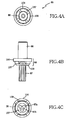
- Figs. 5A-5D shows details of the mounting portion 3.
- a recess 3d is formed at a position to be opposed to the valve device 24.
- the recess 3d has dimensions such that the sealing portion 63 fits in the recess 3d when the ink cartridge 1 is attached to the mounting portion 3.
- the air supply port 91 is formed through a bottom wall constituting the base portion 3a, on the inner side of the sealing portion 63 such that the lower end of the operational part 67 does not close an entirety of the air supply port 91.
- the air supply port is formed through the bottom wall of the base portion 3a to be in communication with an end of the groove of the air supply passage, while the ink cartridge is mounted on the side of the bottom wall or base portion 3a opposite to the side on which the air supply passage is formed.
- the air supply port 91 may be formed in the shape of a slit which has a width smaller than an outer diameter of the operational part 67, and a length larger than the outer diameter of the operation part 67, so that the entirety of the air supply port 91 is not closed by the lower end of the operational part 67 even when this lower end is brought into contact with the air supply port 91.
- the air supply port 91 may have a radial shape made up of a plurality of such slits as arranged in a radial pattern.
- the air supply passage 92 On an undersurface of the base wall constituting the base portion 3a, there is formed the air supply passage 92, which is groove-shaped. One of opposite ends of the air supply passage 92 is enlarged in cross-sectional area and connected to the air supply port 91. The other end of the air supply passage 92 is connected to the air intake port 93 formed through the bottom wall constituting the base portion 3a.
- the air intake port 93 is relatively simple in structure and can be manufactured relatively easily, since the air intake port 93 is formed through the bottom wall of the base portion 3a to be in communication with the other end of the groove opposite to the end in communication with the ink cartridge 1.
- the air supply passage 92 includes a bend portion where the air supply passage 92 turns around a plurality of times on the undersurface of the bottom wall, in order to restrict the air communication with the outside to prevent evaporation of components of the ink including water when the air supply passage 92 is in communication with the air introducing port 26.
- the mounting portion 3 is disposed at the stationary part of the main body of the apparatus 2, and the ink supply pipe 4 connects the ink supply side of the mounting portion 3 and the recording head 7, even in a case where the ink cartridge 1 is the one storing a large volume of ink, there is obtained an effect that the ink can be kept supplied excellently with the evaporation of the ink effectively prevented and the air introduced with stability, throughout the entire period of its use.
- the air intake port 93 is open in an upper surface of the base portion 3a.
- the air intake port 93 is spaced from a bottom face of the ink cartridge 1, so as to enable to supply the atmospheric air into the ink cartridge 1 via the air supply passage 92 and air supply port 91.
- An upper surface of the air intake port 93 may be covered by an elastic porous material 3c (as will be described later), which allows an air communication between the air intake port 93 and the outside.
- an ink drawing tube 12 which is formed integrally with the base portion 3a protrudes on the upper side of the bottom wall of the base portion 3a.
- the ink supply passage 94 is formed on an undersurface of the bottom wall.
- One 94a of opposite ends of the ink supply passage 94 is connected to a lower end of an internal passage defined inside the ink drawing tube 12 and extending over an entire length of the ink drawing tube 12.
- the other end 94b of the ink supply passage 94 is open in an upper surface of an extended part of the base portion 3a which is located outside the guide portions 3b, and the other end 94b is connected to the ink supply pipe 4.
- a communication opening 81a is formed at an upper end of the ink drawing tube 12 so as to allow communication between the internal passage and the ink chamber 16 in a state where the upper end of the ink drawing tube 12 is held in contact with the valve member 32.
- the elastic porous material 3c On the upper surface of the base portion 3a and around the ink drawing tube 12, there is disposed the elastic porous material 3c, which may be of a sponge material. In the event of leakage of the ink from the valve device 23, the elastic porous material absorbs the leaking ink.
- the mounting portion 3 includes a plurality of mounting places arranged in a row, corresponding to the plurality of ink cartridges.
- the wall members constituting the base portion 3a and the guide portions 3b are integrally extended in a direction of extension of the row of the ink cartridges.
- a set of elements comprising the above-described ink drawing tube 12, ink supply passage 94, recess 3d, air supply port 91, air supply passage 92, and air intake port 93 is disposed.
- Each ink supply passage 94 is connected at its one end to the ink supply pipe 4, and these ends of the ink supply passages 94 are arranged in a row in the extended part of the base portion 3a, as shown in Fig. 5B .
- the ink supply passages 94 and air supply passages 92 are formed by covering the open, lower surfaces of grooves with a covering member, e.g., a resin film 95.
- the film 95 is fixed to lower end surfaces of ribs 94c, 92c.
- the ribs 94c define the ink supply passages 94, while the ribs 92c define the air supply passages 92. All the ink supply passages 94 and air supply passages 92 of the plurality of mounting places are together covered by a single film 95.
- This embodiment where the open surfaces of grooves are closed by a covering member to form the air supply passages 92 is advantageous in that air supply passages 92 having a shape including a turn can be formed with a relatively simple structure.
- the ink supply passages 94 for the plural ink cartridges 1 are formed using a single covering member, the structure of the mounting portion 3 is simplified, the number of required components is reduced, and the manufacturing thereof is facilitated. Still further, since the single covering member covers not only the plural grooves constituting the air supply passages 92, but also the plural ink supply passages 94, the effects that the structure of the mounting portion 3 is simplified, the number of required components is reduced, and the manufacturing thereof is facilitated, are further significant.
- FIG. 2A shows the state before the ink cartridge 1 is mounted on the mounting portion 3, where the valve members 32, 65 on both of the ink supply side and the air introduction side are respectively pressed onto the valve seats (valve seat surface and valve seat portion) 46a, 146a, by the elastic force of the support members 46, 146. That is, the valve devices 23, 24 are not opened.
- the valve device 23 is opened by the upper end of the ink drawing tube 12 pushing up the valve member 32 to stretch the side wall portion 36 of the support member 46 so that the valve member 32 is separated from the valve seat surface 46a. Consequently, there is formed a path of ink flow from the ink chamber 16 to the ink drawing tube 12 via the ink supply port 21, the opening 37a of the valve device 23, the communication passage 58, and between the valve member 32 and the valve seat surface 46a. Along this ink passage, the ink is supplied to the recording head 7.
- valve device 23 as closure means functions to close the ink supply port 21 while the ink cartridge 1 is not mounted on the mounting portion 3, and to bring the ink supply port 21 into communication with the ink drawing tube 12 as a part of an ink drawing portion when the ink cartridge 1 is mounted on the mounting portion 3, the effect that the ink supply port 21 and the ink drawing portion can be brought into communication with each other only by mounting the ink cartridge 1 on the mounting portion 3.
- valve device 24 on the air supply side is opened in the following way.
- the lower end of the operational part 67 is brought into contact with the bottom of the recess 3d to push the valve member 65 upward, stretching the side wall portion 136 of the support member 146, so that the valve part 68 of the valve member 65 is separated from the valve seat portion 146a to open the valve device 24.
- the valve device 24 as closure means function to seal the air introducing port 26 of the ink cartridge 1 from the atmospheric air in a state where the ink cartridge 1 is not mounted on the mounting portion 3, and bring the air introducing port 26 into communication with the air supply port 91 when the ink cartridge 1 is mounted on the mounting portion 3.
- the ink cartridge 1 is closed against the atmospheric air to be free from evaporation of the ink while the ink cartridge 1 is not mounted on the mounting portion 3, and introduction of the atmospheric air into the ink cartridge is enabled by mounting the ink cartridge 1 on the mounting portion 3.
- the sealing portion 63 is fitted in close contact with the recess 3d to establish a communication between the air introducing port 26 of the ink cartridge 1 and the air supply port 91 of the mounting portion 3, such that the communication is closed against the outside.
- the atmospheric air is supplied to the upper inner space of the ink chamber 16.
- the inside of the ink cartridge 1 can communicate with the atmospheric air only via the bend portion of the air supply passage 92, thereby inhibiting evaporation of the ink with reliability.
- the fitting of the ink drawing tube 12 in the guiding entrance 40 determines the relative position of the valve device 23 to the mounting portion 3, while the position in the bottom of the recess 3d at which the operational part 67 is brought into contact with the bottom may be anywhere as long as the operation part 67 does not close the air supply port 91 entirely.
- This allows relatively great dimensional tolerances between the ink supply port 21 and the air introducing port 26, and between the valve devices 23 and 24 in the ink cartridge 1, and between the ink drawing tube 12 and the air supply port 91 in the mounting portion 3, and facilitates the operation to mount an ink cartridge on the mounting portion by a user.
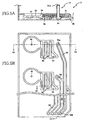
- a tube capable of functioning in a similarly way to the operational part 67 of the first embodiment is formed on both of the air introduction side and the ink supply side. That is, the ink supply side of the mounting portion 3 has an identical structure as that of the first embodiment.
- On the air introduction side there is formed an air supply tube 13, functioning similarly to the ink drawing tube 12, as an operational part pushing up a valve member 265 upon mounting of the ink cartridge 1.
- This air supply tube 13 is a hollow tubular member having an inner space extending through its entire length, and this inner space constitutes an air supply port 291.
- a plurality of communication openings 281a are formed by cutting an upper end of the air supply tube 13 including an upper end surface at which the air supply tube 13 contacts the valve member 265, so that the atmospheric air is supplied via these communication openings 281a.
- a lower end of the air supply port 291 formed inside the air supply tube 13 is connected to an air supply passage 92, in the same way as the first embodiment.
- a support member 246 of a valve device 224 disposed in the communication chamber 50 of the ink cartridge 1 is identical with the support member 46 of the valve device 23.
- the valve member 265 does not have the operational part 67 under its bottom part 257, unlike the first embodiment, and a cylindrical part 266 is formed on the upper side of the bottom part 257.
- the upper end surface of the air supply tube 13 pushes up the valve member 265 to open the valve device 224 on the air introduction side, in the same way as the ink supply side.
- a guiding entrance 240 In a circular bottom wall portion 233 of the support member 246, there is formed a guiding entrance 240.
- the air supply tube 13 is closely fitted in the guiding entrance 240, and this close fitting between the air supply tube 13 and the guiding entrance 240 provides a sealing arrangement or portion.
- the air supply passage may have any other shapes such as a spiral shape, as long as the shape of the air supply passage includes a turn, that is, a point or part at or along which a change of direction takes place.
- valve devices are employed as means for closing the ink supply port 21 and the air introducing port 26, the ports 21, 26 may be closed with rubber members.
- an ink supply tube and an air supply tube are stuck through the respective rubber members, for instance.
Landscapes
- Ink Jet (AREA)
- Particle Formation And Scattering Control In Inkjet Printers (AREA)
- Photographic Developing Apparatuses (AREA)
Claims (16)
- Ein Tintenstrahl-Aufzeichnungsgerät (2), umfassend:einen Aufzeichnungskopf (7), welcher zur Durchführung der Aufzeichnung Tintentröpfchen ausstößt;eine Tintenpatrone (1), welche eine Tintenkammer (16) zum Speichern von Tinte, einen Tintenzuführanschluss (21) zum Liefern der Tinte durch sich hindurch zum Aufzeichnungskopf sowie einen Lufteinführanschluss (26) zum Einführen atmosphärischer Luft durch sich hindurch in die Tintenkammer, besitzt;einen Anbringabschnitt (3), an welchem die Tintenpatrone in abnehmbarer Weise anbringbar ist, und welcher einen Tintenzuführabschnitt (12) zum Liefern der aus der Tintenpatrone gesogenen Tinte zu dem Aufzeichnungskopf sowie einen Lufteinführabschnitt (13; 91, 291; 92, 292; 93) zum Liefern der atmosphärischen Luft in die Tintenkammer, besitzt; undwobei der Lufteinführabschnitt umfaßt:einen Luftzuführanschluss (91, 291), der so angeordnet ist, dass er hinsichtlich seiner Position mit dem Lufteinführanschluss der Tintenpatrone übereinstimmt, wenn die Tintenpatrone in dem Anbringabschnitt angebracht ist;einen Lufteinlassanschluss (93) zum Aufnehmen der atmosphärischen Luft durch sich hindurch; undeinen Luftlieferdurchlass (92, 292), welcher sich zwischen dem Luftzuführanschluss und dem Lufteinlassanschluss erstreckt, und dessen Form eine Wende umfaßt;dadurch gekennzeichnet, dass der Luftlieferdurchlass des Lufteinführabschnitts umfaßt:eine Nut (92, 292), die in einer ersten entgegen gesetzter Oberflächen eines Wandelements (3a) ausgebildet ist, welches den Anbringabschnitt aufbaut;und ein Bedeckungselement (95), welches an dem Wandelement (3a) befestigt ist, um eine offene Oberfläche der Nut zu bedecken.
- Das Tintenstrahl-Aufzeichnungsgerät gemäß Anspruch 1, wobei die Form des Luftlieferdurchlasses labyrinthisch ist.
- Das Tintenstrahl-Aufzeichnungsgerät gemäß Anspruch 1 oder 2, wobei die Form des Luftlieferdurchlasses in naher Umgebung mehrfache Wenden aufweist.
- Das Tintenstrahl-Aufzeichnungsgerät gemäß einem der Ansprüche 1 bis 3,
wobei der Tintenzuführabschnitt (12) einen Tintenzuführdurchlass (94) umfaßt, von welchem ein Teil durch eine Nut aufgebaut wird, die in der ersten der entgegen gesetzten Oberflächen des Wandelements (3a) ausgebildet ist und durch das Bedeckungselement (95) bedeckt ist. - Das Tintenstrahl-Aufzeichnungsgerät gemäß einem der Ansprüche 1 bis 4, wobei die Tintenpatrone auf einer zweiten der entgegen gesetzten Oberflächen des Wandelements des Anbringabschnitts anbringbar ist, und wobei der Luftzuführanschluss durch das Wandelement hindurch ausgebildet ist, um in Verbindung mit einem ersten entgegen gesetzter Enden der Nut des Luftlieferdurchlasses in Verbindung zu stehen.
- Das Tintenstrahl-Aufzeichnungsgerät gemäß einem der Ansprüche 1 bis 5, wobei der Lufteinlassanschluss durch das Wandelement hindurch ausgebildet ist, um in Verbindung mit einem zweiten der entgegen gesetzten Enden der Nut in Verbindung zu stehen.
- Das Tintenstrahl-Aufzeichnungsgerät gemäß Anspruch 6, wobei der Lufteinlassanschluss eine Öffnung in der zweiten Oberfläche des Wandelements besitzt, und wobei die Öffnung durch ein elastisch-poröses Material (3c) bedeckt ist, welches eine Luftverbindung erlaubt und sich um den Tintenzuführabschnitt des Anbringabschnitts herum erstreckt.
- Das Tintenstrahl-Aufzeichnungsgerät gemäß Anspruch 5, wobei der Tintenzuführanschluss in der zweiten Oberfläche des Wandelements geöffnet ist, das Gerät ferner ein Abdichtelement umfaßt, welches zwischen der Tintenpatrone und dem Anbringabschnitt angeordnet ist, wenn die Tintenpatrone in dem Anbringabschnitt angebracht ist, und das Abdichtelement eine Verbindung zwischen dem Lufteinführanschluss der Tintenpatrone und dem Luftzuführanschluss des Anbringabschnitts derart herstellt, dass die zwei Anschlüsse gegenüber dem äußeren abgedichtet sind.
- Das Tintenstrahl-Aufzeichnungsgerät gemäß einem der Ansprüche 1 bis 8, wobei die Tintenpatrone ein Verschlussmittel besitzt, welches den Lufteinführanschluss gegenüber der atmosphärischen Luft in einem Zustand verschließt, in welchem die Tintenpatrone nicht in dem Anbringabschnitt angebracht ist, und welches die Verbindung zwischen dem Lufteinführanschluss und dem Luftzuführanschluss herstellt, wenn die Tintenpatrone in dem Anbringabschnitt angebracht ist.
- Das Tintenstrahl-Aufzeichnungsgerät gemäß Anspruch 9, wobei das Verschlussmittel ein Ventilelement und einen Ventilsitzabschnitt besitzt, welcher aus einem elastischen Material gebildet ist und auf welchem das Ventilelement sitzt, und wobei das Dichtelement mit dem Ventilsitzabschnitt verbunden ist.
- Das Tintenstrahl-Aufzeichnungsgerät gemäß Anspruch 10, wobei das Ventilelement einen Vorsprung (67) aufweist, welcher in Kontakt mit der zweiten Oberfläche des Wandelements gebracht wird, wenn die Tintenpatrone in dem Anbringabschnitt angebracht ist, so dass das Ventilelement von dem Ventilsitzabschnitt getrennt ist und der Lufteinführanschluss mit dem Luftzuführanschluss in Verbindung steht, wobei der Vorsprung den Luftzuführanschluss nicht vollständig verschließt, wenn er in Kontakt mit der zweiten Oberfläche gebracht wird.
- Das Tintenstrahl-Aufzeichnungsgerät gemäß Anspruch 9,
wobei der Luftzuführanschluss aus einem inneren Raum aufgebaut wird, der sich durch eine Röhre erstreckt, die von der zweiten Oberfläche des Wandelements hervorsteht, wobei die Röhre in den Lufteinführanschluss eingesetzt ist, wenn die Tintenpatrone in dem Anbringabschnitt angebracht ist,
und wobei das Dichtelement zwischen einer äußeren Oberfläche der Röhre und dem Lufteinführanschluss aufgenommen ist. - Das Tintenstrahl-Aufzeichnungsgerät gemäß einem der Ansprüche 1 bis 12, wobei die Tintenpatrone ein Verschlussmittel umfaßt, welches den Tintenzuführanschluss in einem Zustand verschließt, in welchem die Tintenpatrone nicht an dem Anbringabschnitt angebracht ist, und welches den Tintenzuführanschluss öffnet, um eine Verbindung zwischen dem Tintenzuführanschluss und dem Tintenzuführabschnitt herzustellen, wenn die Tintenpatrone in dem Anbringabschnitt angebracht ist.
- Das Tintenstrahl-Aufzeichnungsgerät gemäß Anspruch 5,
wobei der Anbringabschnitt eine Vielzahl integral ausgebildeter Anbringorte besitzt, auf welchem jeweils die Tintenpatrone abnehmbar anbringbar ist, wobei die Anbringorte in einer Reihe auf der zweiten Oberfläche des Wandelements angeordnet sind,
und wobei die Nut, die den Luftlieferdurchlass des Lufteinführabschnitts aufbaut, in der ersten Oberfläche des Wandelements an einer Position ausgebildet ist, welche mit jedem der Anbringorte übereinstimmt, und wobei das Bedeckungselement sich quer über die Anbringorte erstreckt, um die offenen Oberflächen der betreffenden Nuten zu bedecken. - Das Tintenstrahl-Aufzeichnungsgerät gemäß Anspruch 14, umfassend eine Vielzahl von Aufzeichnungsköpfen, und
wobei der Tintenzuführabschnitt auf der zweiten Oberfläche des Wandelements an jedem der Anbringorte vorgesehen ist,
wobei eine Vielzahl von Tintenlieferdurchlässen in der ersten Oberfläche des Wandelements ausgebildet sind, und eines von gegenüberliegenden Enden jedes der Tintenlieferdurchlässe mit einem entsprechenden der Tintenzuführabschnitte verbunden ist, während das andere Ende des jeweiligen Tintenzuführdurchlasses mit einem entsprechenden der Aufzeichnungsköpfe verbunden ist,
und wobei das Bedeckungselement an dem Wandelement befestigt ist, um die offenen Oberflächen der Nuten der Tintenlieferdurchlässe sowie offene Oberflächen der Tintenlieferdurchlässe zu bedecken. - Das Tintenstrahl-Aufzeichnungsgerät gemäß einem der Ansprüche 1 bis 15, umfassend einen Hauptkörper, und wobei der Anbringabschnitt in einem stationären Teil des Hauptkörpers angeordnet ist, und wobei der Tintenzuführabschnitt und der Aufzeichnungskopf mithilfe einer Tintenlieferleitung verbunden sind.
Applications Claiming Priority (2)
| Application Number | Priority Date | Filing Date | Title |
|---|---|---|---|
| JP2004060395 | 2004-03-04 | ||
| JP2004060395A JP4496806B2 (ja) | 2004-03-04 | 2004-03-04 | インクジェット記録装置 |
Publications (2)
| Publication Number | Publication Date |
|---|---|
| EP1570996A1 EP1570996A1 (de) | 2005-09-07 |
| EP1570996B1 true EP1570996B1 (de) | 2010-11-17 |
Family
ID=34747664
Family Applications (1)
| Application Number | Title | Priority Date | Filing Date |
|---|---|---|---|
| EP05004680A Expired - Lifetime EP1570996B1 (de) | 2004-03-04 | 2005-03-03 | Tintenstrahlaufzeichnungsgerät |
Country Status (5)
| Country | Link |
|---|---|
| US (1) | US7354143B2 (de) |
| EP (1) | EP1570996B1 (de) |
| JP (1) | JP4496806B2 (de) |
| AT (1) | ATE488371T1 (de) |
| DE (1) | DE602005024733D1 (de) |
Families Citing this family (9)
| Publication number | Priority date | Publication date | Assignee | Title |
|---|---|---|---|---|
| JP5168873B2 (ja) * | 2006-10-06 | 2013-03-27 | ブラザー工業株式会社 | インクカートリッジ |
| JP5277622B2 (ja) * | 2007-11-30 | 2013-08-28 | ブラザー工業株式会社 | インク供給装置およびカートリッジ収容装置 |
| JP4561853B2 (ja) * | 2008-03-27 | 2010-10-13 | ブラザー工業株式会社 | 液滴吐出装置及び液体カートリッジ |
| JP5471461B2 (ja) * | 2010-01-08 | 2014-04-16 | セイコーエプソン株式会社 | 液体容器および液体噴射装置 |
| JP5471892B2 (ja) * | 2010-06-29 | 2014-04-16 | ブラザー工業株式会社 | 液体吐出ヘッド及びこれを有する液体吐出装置 |
| US9254672B2 (en) * | 2012-03-19 | 2016-02-09 | Hewlett-Packard Development Company, L.P. | Vent through a printhead support structure |
| DE112013007565T5 (de) * | 2013-11-27 | 2016-07-14 | Hewlett-Packard Development Company, L.P. | Anordnung für Druckkopf mit mehreren Luftkanälen |
| EP3160754A4 (de) * | 2014-06-26 | 2018-01-24 | Hewlett-Packard Development Company, L.P. | Behälteranordnung |
| JP6361342B2 (ja) * | 2014-07-14 | 2018-07-25 | ブラザー工業株式会社 | 液体吐出装置 |
Family Cites Families (15)
| Publication number | Priority date | Publication date | Assignee | Title |
|---|---|---|---|---|
| JP2929804B2 (ja) | 1991-10-05 | 1999-08-03 | 富士ゼロックス株式会社 | インクジェットプリンタのインク供給機構 |
| JP3374209B2 (ja) | 1994-11-18 | 2003-02-04 | セイコーエプソン株式会社 | インクジェットプリンタ用インク供給装置 |
| JP3417750B2 (ja) | 1996-02-01 | 2003-06-16 | ブラザー工業株式会社 | インクジェットプリンタのインクカートリッジ |
| US5992988A (en) | 1995-12-05 | 1999-11-30 | Brother Kogyo Kabushiki Kaisha | Ink cartridge having an atmosphere communicating channel of labyrinthine structure |
| JPH09240002A (ja) * | 1996-03-05 | 1997-09-16 | Ricoh Co Ltd | インクジェット記録装置 |
| US5949459A (en) * | 1997-06-04 | 1999-09-07 | Hewlett-Packard Company | Method and apparatus for securing an ink container |
| JPH1178048A (ja) * | 1997-09-03 | 1999-03-23 | Fuji Photo Film Co Ltd | プリンタのインクタンク装置 |
| JPH11129492A (ja) * | 1997-10-29 | 1999-05-18 | Seiko Epson Corp | インクカートリッヂにおける大気開放装置 |
| DE69911744T2 (de) * | 1998-02-13 | 2004-07-29 | Seiko Epson Corp. | Tintenstrahldrucker, dafür geeignete tanktureinheit und verfahren zur wiederherstellung des tintentröpfchenausstossvermögens |
| DE69918368T2 (de) | 1998-04-28 | 2005-08-18 | Canon K.K. | Tintenstrahlaufzeichnungsvorrichtung |
| JP3852256B2 (ja) * | 1999-11-10 | 2006-11-29 | 富士ゼロックス株式会社 | インクジェット記録装置 |
| JP2001187459A (ja) * | 1999-12-28 | 2001-07-10 | Fuji Xerox Co Ltd | インクジェット記録装置 |
| JP3873562B2 (ja) * | 2000-02-09 | 2007-01-24 | セイコーエプソン株式会社 | 弁構造体の製造方法 |
| KR100388332B1 (ko) | 2000-02-16 | 2003-06-25 | 세이코 엡슨 가부시키가이샤 | 잉크젯 기록 장치용 잉크 카트리지, 접속 유닛 및 잉크젯기록 장치 |
| JP3832225B2 (ja) * | 2000-10-17 | 2006-10-11 | 富士ゼロックス株式会社 | インク補給装置、インクジェット記録装置及びインク補給方法 |
-
2004
- 2004-03-04 JP JP2004060395A patent/JP4496806B2/ja not_active Expired - Fee Related
-
2005
- 2005-03-02 US US11/070,802 patent/US7354143B2/en not_active Expired - Lifetime
- 2005-03-03 DE DE602005024733T patent/DE602005024733D1/de not_active Expired - Lifetime
- 2005-03-03 EP EP05004680A patent/EP1570996B1/de not_active Expired - Lifetime
- 2005-03-03 AT AT05004680T patent/ATE488371T1/de not_active IP Right Cessation
Also Published As
| Publication number | Publication date |
|---|---|
| US7354143B2 (en) | 2008-04-08 |
| JP2005246780A (ja) | 2005-09-15 |
| ATE488371T1 (de) | 2010-12-15 |
| DE602005024733D1 (de) | 2010-12-30 |
| US20050195251A1 (en) | 2005-09-08 |
| HK1080803A1 (en) | 2006-05-04 |
| JP4496806B2 (ja) | 2010-07-07 |
| EP1570996A1 (de) | 2005-09-07 |
Similar Documents
| Publication | Publication Date | Title |
|---|---|---|
| JP5380829B2 (ja) | インクカートリッジ、及びインク供給装置 | |
| EP1557272B1 (de) | Tintenpatrone und Tintenstrahldrucker mit einer solchen Patrone | |
| EP1918111B1 (de) | Tintenpatrone | |
| US20050195254A1 (en) | Ink cartridges and methods of filling ink cartridges | |
| JP2010221470A (ja) | 液体容器 | |
| EP1570996B1 (de) | Tintenstrahlaufzeichnungsgerät | |
| CN103600586A (zh) | 液体供应系统及液体喷射装置 | |
| JP5088515B2 (ja) | 液体噴射装置 | |
| JP2005262563A (ja) | インク充填方法 | |
| EP4151419B1 (de) | Tintennachfüllbehälter | |
| EP1674270B1 (de) | Tintenpatrone | |
| JP4529498B2 (ja) | 液体収容体、液体噴射装置 | |
| JP4813760B2 (ja) | インクカートリッジ | |
| JP4492150B2 (ja) | インクカートリッジおよび記録システム | |
| JP4479280B2 (ja) | インクジェット記録装置 | |
| HK1080803B (en) | Inkjet recording apparatus | |
| JP4403790B2 (ja) | インクカートリッジ及びインクジェット記録装置 | |
| US12172447B2 (en) | Ink replenishment container | |
| JP4424011B2 (ja) | インクカートリッジ | |
| CN118494023A (zh) | 油墨补给容器 | |
| HK1091442B (en) | Ink cartridge | |
| JP2005297388A (ja) | 液体噴射装置およびそれに用いる液体カートリッジ | |
| HK1087073B (en) | Ink cartridge | |
| HK1087073A1 (zh) | 墨盒 | |
| JP2005111853A (ja) | バルブ装置及び液体噴射装置 |
Legal Events
| Date | Code | Title | Description |
|---|---|---|---|
| PUAI | Public reference made under article 153(3) epc to a published international application that has entered the european phase |
Free format text: ORIGINAL CODE: 0009012 |
|
| AK | Designated contracting states |
Kind code of ref document: A1 Designated state(s): AT BE BG CH CY CZ DE DK EE ES FI FR GB GR HU IE IS IT LI LT LU MC NL PL PT RO SE SI SK TR |
|
| AX | Request for extension of the european patent |
Extension state: AL BA HR LV MK YU |
|
| 17P | Request for examination filed |
Effective date: 20060113 |
|
| REG | Reference to a national code |
Ref country code: HK Ref legal event code: DE Ref document number: 1080803 Country of ref document: HK |
|
| AKX | Designation fees paid |
Designated state(s): AT BE BG CH CY CZ DE DK EE ES FI FR GB GR HU IE IS IT LI LT LU MC NL PL PT RO SE SI SK TR |
|
| 17Q | First examination report despatched |
Effective date: 20071031 |
|
| GRAP | Despatch of communication of intention to grant a patent |
Free format text: ORIGINAL CODE: EPIDOSNIGR1 |
|
| GRAS | Grant fee paid |
Free format text: ORIGINAL CODE: EPIDOSNIGR3 |
|
| GRAA | (expected) grant |
Free format text: ORIGINAL CODE: 0009210 |
|
| AK | Designated contracting states |
Kind code of ref document: B1 Designated state(s): AT BE BG CH CY CZ DE DK EE ES FI FR GB GR HU IE IS IT LI LT LU MC NL PL PT RO SE SI SK TR |
|
| REG | Reference to a national code |
Ref country code: GB Ref legal event code: FG4D |
|
| REG | Reference to a national code |
Ref country code: CH Ref legal event code: EP |
|
| REG | Reference to a national code |
Ref country code: IE Ref legal event code: FG4D |
|
| REF | Corresponds to: |
Ref document number: 602005024733 Country of ref document: DE Date of ref document: 20101230 Kind code of ref document: P |
|
| REG | Reference to a national code |
Ref country code: HK Ref legal event code: GR Ref document number: 1080803 Country of ref document: HK |
|
| REG | Reference to a national code |
Ref country code: NL Ref legal event code: VDEP Effective date: 20101117 |
|
| LTIE | Lt: invalidation of european patent or patent extension |
Effective date: 20101117 |
|
| PG25 | Lapsed in a contracting state [announced via postgrant information from national office to epo] |
Ref country code: LT Free format text: LAPSE BECAUSE OF FAILURE TO SUBMIT A TRANSLATION OF THE DESCRIPTION OR TO PAY THE FEE WITHIN THE PRESCRIBED TIME-LIMIT Effective date: 20101117 |
|
| PG25 | Lapsed in a contracting state [announced via postgrant information from national office to epo] |
Ref country code: SE Free format text: LAPSE BECAUSE OF FAILURE TO SUBMIT A TRANSLATION OF THE DESCRIPTION OR TO PAY THE FEE WITHIN THE PRESCRIBED TIME-LIMIT Effective date: 20101117 Ref country code: BG Free format text: LAPSE BECAUSE OF FAILURE TO SUBMIT A TRANSLATION OF THE DESCRIPTION OR TO PAY THE FEE WITHIN THE PRESCRIBED TIME-LIMIT Effective date: 20110217 Ref country code: AT Free format text: LAPSE BECAUSE OF FAILURE TO SUBMIT A TRANSLATION OF THE DESCRIPTION OR TO PAY THE FEE WITHIN THE PRESCRIBED TIME-LIMIT Effective date: 20101117 Ref country code: NL Free format text: LAPSE BECAUSE OF FAILURE TO SUBMIT A TRANSLATION OF THE DESCRIPTION OR TO PAY THE FEE WITHIN THE PRESCRIBED TIME-LIMIT Effective date: 20101117 Ref country code: CY Free format text: LAPSE BECAUSE OF FAILURE TO SUBMIT A TRANSLATION OF THE DESCRIPTION OR TO PAY THE FEE WITHIN THE PRESCRIBED TIME-LIMIT Effective date: 20101117 Ref country code: IS Free format text: LAPSE BECAUSE OF FAILURE TO SUBMIT A TRANSLATION OF THE DESCRIPTION OR TO PAY THE FEE WITHIN THE PRESCRIBED TIME-LIMIT Effective date: 20110317 Ref country code: PT Free format text: LAPSE BECAUSE OF FAILURE TO SUBMIT A TRANSLATION OF THE DESCRIPTION OR TO PAY THE FEE WITHIN THE PRESCRIBED TIME-LIMIT Effective date: 20110317 Ref country code: FI Free format text: LAPSE BECAUSE OF FAILURE TO SUBMIT A TRANSLATION OF THE DESCRIPTION OR TO PAY THE FEE WITHIN THE PRESCRIBED TIME-LIMIT Effective date: 20101117 Ref country code: SI Free format text: LAPSE BECAUSE OF FAILURE TO SUBMIT A TRANSLATION OF THE DESCRIPTION OR TO PAY THE FEE WITHIN THE PRESCRIBED TIME-LIMIT Effective date: 20101117 |
|
| PG25 | Lapsed in a contracting state [announced via postgrant information from national office to epo] |
Ref country code: GR Free format text: LAPSE BECAUSE OF FAILURE TO SUBMIT A TRANSLATION OF THE DESCRIPTION OR TO PAY THE FEE WITHIN THE PRESCRIBED TIME-LIMIT Effective date: 20110218 |
|
| PG25 | Lapsed in a contracting state [announced via postgrant information from national office to epo] |
Ref country code: CZ Free format text: LAPSE BECAUSE OF FAILURE TO SUBMIT A TRANSLATION OF THE DESCRIPTION OR TO PAY THE FEE WITHIN THE PRESCRIBED TIME-LIMIT Effective date: 20101117 Ref country code: ES Free format text: LAPSE BECAUSE OF FAILURE TO SUBMIT A TRANSLATION OF THE DESCRIPTION OR TO PAY THE FEE WITHIN THE PRESCRIBED TIME-LIMIT Effective date: 20110228 Ref country code: BE Free format text: LAPSE BECAUSE OF FAILURE TO SUBMIT A TRANSLATION OF THE DESCRIPTION OR TO PAY THE FEE WITHIN THE PRESCRIBED TIME-LIMIT Effective date: 20101117 Ref country code: EE Free format text: LAPSE BECAUSE OF FAILURE TO SUBMIT A TRANSLATION OF THE DESCRIPTION OR TO PAY THE FEE WITHIN THE PRESCRIBED TIME-LIMIT Effective date: 20101117 |
|
| PG25 | Lapsed in a contracting state [announced via postgrant information from national office to epo] |
Ref country code: PL Free format text: LAPSE BECAUSE OF FAILURE TO SUBMIT A TRANSLATION OF THE DESCRIPTION OR TO PAY THE FEE WITHIN THE PRESCRIBED TIME-LIMIT Effective date: 20101117 Ref country code: DK Free format text: LAPSE BECAUSE OF FAILURE TO SUBMIT A TRANSLATION OF THE DESCRIPTION OR TO PAY THE FEE WITHIN THE PRESCRIBED TIME-LIMIT Effective date: 20101117 Ref country code: RO Free format text: LAPSE BECAUSE OF FAILURE TO SUBMIT A TRANSLATION OF THE DESCRIPTION OR TO PAY THE FEE WITHIN THE PRESCRIBED TIME-LIMIT Effective date: 20101117 Ref country code: SK Free format text: LAPSE BECAUSE OF FAILURE TO SUBMIT A TRANSLATION OF THE DESCRIPTION OR TO PAY THE FEE WITHIN THE PRESCRIBED TIME-LIMIT Effective date: 20101117 |
|
| PLBE | No opposition filed within time limit |
Free format text: ORIGINAL CODE: 0009261 |
|
| STAA | Information on the status of an ep patent application or granted ep patent |
Free format text: STATUS: NO OPPOSITION FILED WITHIN TIME LIMIT |
|
| 26N | No opposition filed |
Effective date: 20110818 |
|
| PG25 | Lapsed in a contracting state [announced via postgrant information from national office to epo] |
Ref country code: MC Free format text: LAPSE BECAUSE OF NON-PAYMENT OF DUE FEES Effective date: 20110331 |
|
| REG | Reference to a national code |
Ref country code: CH Ref legal event code: PL |
|
| REG | Reference to a national code |
Ref country code: DE Ref legal event code: R097 Ref document number: 602005024733 Country of ref document: DE Effective date: 20110818 |
|
| PG25 | Lapsed in a contracting state [announced via postgrant information from national office to epo] |
Ref country code: IT Free format text: LAPSE BECAUSE OF FAILURE TO SUBMIT A TRANSLATION OF THE DESCRIPTION OR TO PAY THE FEE WITHIN THE PRESCRIBED TIME-LIMIT Effective date: 20101117 |
|
| REG | Reference to a national code |
Ref country code: IE Ref legal event code: MM4A |
|
| PG25 | Lapsed in a contracting state [announced via postgrant information from national office to epo] |
Ref country code: IE Free format text: LAPSE BECAUSE OF NON-PAYMENT OF DUE FEES Effective date: 20110303 Ref country code: LI Free format text: LAPSE BECAUSE OF NON-PAYMENT OF DUE FEES Effective date: 20110331 Ref country code: CH Free format text: LAPSE BECAUSE OF NON-PAYMENT OF DUE FEES Effective date: 20110331 |
|
| PG25 | Lapsed in a contracting state [announced via postgrant information from national office to epo] |
Ref country code: LU Free format text: LAPSE BECAUSE OF NON-PAYMENT OF DUE FEES Effective date: 20110303 |
|
| PG25 | Lapsed in a contracting state [announced via postgrant information from national office to epo] |
Ref country code: TR Free format text: LAPSE BECAUSE OF FAILURE TO SUBMIT A TRANSLATION OF THE DESCRIPTION OR TO PAY THE FEE WITHIN THE PRESCRIBED TIME-LIMIT Effective date: 20101117 |
|
| PG25 | Lapsed in a contracting state [announced via postgrant information from national office to epo] |
Ref country code: HU Free format text: LAPSE BECAUSE OF FAILURE TO SUBMIT A TRANSLATION OF THE DESCRIPTION OR TO PAY THE FEE WITHIN THE PRESCRIBED TIME-LIMIT Effective date: 20101117 |
|
| REG | Reference to a national code |
Ref country code: FR Ref legal event code: PLFP Year of fee payment: 12 |
|
| REG | Reference to a national code |
Ref country code: FR Ref legal event code: PLFP Year of fee payment: 13 |
|
| REG | Reference to a national code |
Ref country code: FR Ref legal event code: PLFP Year of fee payment: 14 |
|
| PGFP | Annual fee paid to national office [announced via postgrant information from national office to epo] |
Ref country code: GB Payment date: 20180223 Year of fee payment: 14 |
|
| PGFP | Annual fee paid to national office [announced via postgrant information from national office to epo] |
Ref country code: FR Payment date: 20180223 Year of fee payment: 14 |
|
| PGFP | Annual fee paid to national office [announced via postgrant information from national office to epo] |
Ref country code: DE Payment date: 20190215 Year of fee payment: 15 |
|
| GBPC | Gb: european patent ceased through non-payment of renewal fee |
Effective date: 20190303 |
|
| PG25 | Lapsed in a contracting state [announced via postgrant information from national office to epo] |
Ref country code: GB Free format text: LAPSE BECAUSE OF NON-PAYMENT OF DUE FEES Effective date: 20190303 |
|
| PG25 | Lapsed in a contracting state [announced via postgrant information from national office to epo] |
Ref country code: FR Free format text: LAPSE BECAUSE OF NON-PAYMENT OF DUE FEES Effective date: 20190331 |
|
| REG | Reference to a national code |
Ref country code: DE Ref legal event code: R119 Ref document number: 602005024733 Country of ref document: DE |
|
| PG25 | Lapsed in a contracting state [announced via postgrant information from national office to epo] |
Ref country code: DE Free format text: LAPSE BECAUSE OF NON-PAYMENT OF DUE FEES Effective date: 20201001 |