EP4151419B1 - Tintennachfüllbehälter - Google Patents
Tintennachfüllbehälter Download PDFInfo
- Publication number
- EP4151419B1 EP4151419B1 EP22196039.6A EP22196039A EP4151419B1 EP 4151419 B1 EP4151419 B1 EP 4151419B1 EP 22196039 A EP22196039 A EP 22196039A EP 4151419 B1 EP4151419 B1 EP 4151419B1
- Authority
- EP
- European Patent Office
- Prior art keywords
- ink
- valve
- flow path
- replenishment container
- valve body
- Prior art date
- Legal status (The legal status is an assumption and is not a legal conclusion. Google has not performed a legal analysis and makes no representation as to the accuracy of the status listed.)
- Active
Links
Images


Classifications
-
- B—PERFORMING OPERATIONS; TRANSPORTING
- B41—PRINTING; LINING MACHINES; TYPEWRITERS; STAMPS
- B41J—TYPEWRITERS; SELECTIVE PRINTING MECHANISMS, i.e. MECHANISMS PRINTING OTHERWISE THAN FROM A FORME; CORRECTION OF TYPOGRAPHICAL ERRORS
- B41J2/00—Typewriters or selective printing mechanisms characterised by the printing or marking process for which they are designed
- B41J2/005—Typewriters or selective printing mechanisms characterised by the printing or marking process for which they are designed characterised by bringing liquid or particles selectively into contact with a printing material
- B41J2/01—Ink jet
- B41J2/17—Ink jet characterised by ink handling
- B41J2/175—Ink supply systems ; Circuit parts therefor
- B41J2/17503—Ink cartridges
- B41J2/17506—Refilling of the cartridge
- B41J2/17509—Whilst mounted in the printer
-
- B—PERFORMING OPERATIONS; TRANSPORTING
- B41—PRINTING; LINING MACHINES; TYPEWRITERS; STAMPS
- B41J—TYPEWRITERS; SELECTIVE PRINTING MECHANISMS, i.e. MECHANISMS PRINTING OTHERWISE THAN FROM A FORME; CORRECTION OF TYPOGRAPHICAL ERRORS
- B41J2/00—Typewriters or selective printing mechanisms characterised by the printing or marking process for which they are designed
- B41J2/005—Typewriters or selective printing mechanisms characterised by the printing or marking process for which they are designed characterised by bringing liquid or particles selectively into contact with a printing material
- B41J2/01—Ink jet
- B41J2/17—Ink jet characterised by ink handling
- B41J2/175—Ink supply systems ; Circuit parts therefor
- B41J2/17503—Ink cartridges
- B41J2/17513—Inner structure
-
- B—PERFORMING OPERATIONS; TRANSPORTING
- B41—PRINTING; LINING MACHINES; TYPEWRITERS; STAMPS
- B41J—TYPEWRITERS; SELECTIVE PRINTING MECHANISMS, i.e. MECHANISMS PRINTING OTHERWISE THAN FROM A FORME; CORRECTION OF TYPOGRAPHICAL ERRORS
- B41J2/00—Typewriters or selective printing mechanisms characterised by the printing or marking process for which they are designed
- B41J2/005—Typewriters or selective printing mechanisms characterised by the printing or marking process for which they are designed characterised by bringing liquid or particles selectively into contact with a printing material
- B41J2/01—Ink jet
- B41J2/17—Ink jet characterised by ink handling
- B41J2/175—Ink supply systems ; Circuit parts therefor
- B41J2/17503—Ink cartridges
- B41J2/1752—Mounting within the printer
- B41J2/17523—Ink connection
-
- B—PERFORMING OPERATIONS; TRANSPORTING
- B41—PRINTING; LINING MACHINES; TYPEWRITERS; STAMPS
- B41J—TYPEWRITERS; SELECTIVE PRINTING MECHANISMS, i.e. MECHANISMS PRINTING OTHERWISE THAN FROM A FORME; CORRECTION OF TYPOGRAPHICAL ERRORS
- B41J2/00—Typewriters or selective printing mechanisms characterised by the printing or marking process for which they are designed
- B41J2/005—Typewriters or selective printing mechanisms characterised by the printing or marking process for which they are designed characterised by bringing liquid or particles selectively into contact with a printing material
- B41J2/01—Ink jet
- B41J2/17—Ink jet characterised by ink handling
- B41J2/175—Ink supply systems ; Circuit parts therefor
- B41J2/17596—Ink pumps, ink valves
-
- B—PERFORMING OPERATIONS; TRANSPORTING
- B41—PRINTING; LINING MACHINES; TYPEWRITERS; STAMPS
- B41J—TYPEWRITERS; SELECTIVE PRINTING MECHANISMS, i.e. MECHANISMS PRINTING OTHERWISE THAN FROM A FORME; CORRECTION OF TYPOGRAPHICAL ERRORS
- B41J2/00—Typewriters or selective printing mechanisms characterised by the printing or marking process for which they are designed
- B41J2/005—Typewriters or selective printing mechanisms characterised by the printing or marking process for which they are designed characterised by bringing liquid or particles selectively into contact with a printing material
- B41J2/01—Ink jet
- B41J2/17—Ink jet characterised by ink handling
- B41J2/175—Ink supply systems ; Circuit parts therefor
- B41J2/17503—Ink cartridges
- B41J2/17536—Protection of cartridges or parts thereof, e.g. tape
- B41J2/1754—Protection of cartridges or parts thereof, e.g. tape with means attached to the cartridge, e.g. protective cap
-
- B—PERFORMING OPERATIONS; TRANSPORTING
- B41—PRINTING; LINING MACHINES; TYPEWRITERS; STAMPS
- B41J—TYPEWRITERS; SELECTIVE PRINTING MECHANISMS, i.e. MECHANISMS PRINTING OTHERWISE THAN FROM A FORME; CORRECTION OF TYPOGRAPHICAL ERRORS
- B41J2/00—Typewriters or selective printing mechanisms characterised by the printing or marking process for which they are designed
- B41J2/005—Typewriters or selective printing mechanisms characterised by the printing or marking process for which they are designed characterised by bringing liquid or particles selectively into contact with a printing material
- B41J2/01—Ink jet
- B41J2/17—Ink jet characterised by ink handling
- B41J2/175—Ink supply systems ; Circuit parts therefor
- B41J2/17566—Ink level or ink residue control
- B41J2002/17573—Ink level or ink residue control using optical means for ink level indication
Definitions
- the present disclosure relates to an ink replenishment container.
- an inkjet printer capable of performing a print with ink on a printing medium such as printing paper by ejecting the ink from a print head toward the printing medium.
- a printing medium such as printing paper
- Such an inkjet printer is an ink replenishment type printer that is used by replenishing ink in an ink tank.
- JP-A-2018-144281 discloses an ink replenishment container used for replenishing ink to an ink tank having an ink replenishment type.
- the ink replenishment container in JP-A-2018-144281 has room for improvement from the viewpoint of quickly replenishing a liquid or facilitating the manufacture or maintenance of the ink replenishment container.
- An ink replenishment container having a configuration in which at least one of these improvements is improved is desired.
- US 2021/253312 discloses a liquid storage bottle that stores a liquid with which a liquid tank is replenished, has a bottle body and a discharge port that discharges a liquid stored in the bottle body, and has a discharge nozzle in which a liquid injection tube of the liquid tank can be inserted via the discharge port and an annular fixed seal member that is provided to the discharge port and seals a part between the discharge port and the liquid injection tube inserted in the discharge port.
- the fixed seal member has a plurality of annular seal portions that are arranged apart from each other in the axis direction of a discharge nozzle and are individually in contact with the liquid injection tube inserted in the discharge port.
- EP 1403067 , US 2018/250944 , US 2005/088497 and EP 3381697 are also relevant.
- an ink replenishment container as defined in claim 1.
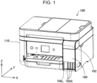
- FIG. 1 is a perspective view of a printer 100 according to a first embodiment.
- the printer 100 is an ink jet printer that ejects ink onto a printing medium for printing.
- XYZ axes orthogonal to each other are drawn.
- the X-axis corresponds to a width direction of the printer 100
- the Y-axis corresponds to a depth direction of the printer 100
- the Z-axis corresponds to a height direction of the printer 100.
- the printer 100 is installed on a horizontal installation surface defined by the X-axis direction and the Y-axis direction.
- the "X-axis direction" means a concept in which a +X direction and a -X direction are combined.
- the "Y-axis direction” means a concept in which a +Y direction and a -Y direction are combined
- the "Z-axis direction” means a concept in which a +Z direction and a -Z direction are combined.
- the printer 100 has a housing 110. Inside the housing 110, a carriage (not illustrated) that can move in a main scanning direction (X-axis direction) is provided. The carriage is provided with a print head that ejects ink onto a printing medium.
- An ink tank accommodating unit 160 accommodating a plurality of ink tanks 700S and 700L is provided at one end of a front surface of the housing 110.
- the ink tank accommodating unit 160 has a lid 162 that can be opened and closed at a top portion of the ink tank accommodating unit 160.
- the ink tank 700S is a small-capacity tank
- the ink tank 700L is a large-capacity tank.
- each ink tank 700 is coupled to a print head of the carriage by a tube (not illustrated). That is, the ink tank 700 is a stationary ink tank that is not mounted on the carriage of the printer 100. Further, each ink tank 700 is an ink replenishment type ink tank to which ink is replenished from an ink replenishment container when the remaining amount of ink is low. In the present embodiment, the ink tank 700 is a stationary ink tank, and the ink tank 700 may be mounted on the carriage of the printer 100.
- FIG. 2 is a perspective view illustrating a state in which ink is replenished to the ink tank 700 by using an ink replenishment container 200.
- a front surface of each ink tank 700 is formed of a transparent member, and the remaining amount of ink in each ink tank 700 can be visually recognized from an outside. When the remaining amount of ink is low, as illustrated in FIG. 2 , it is possible to open the lid 162 and replenish ink from an ink inlet flow path member 710 of the ink tank 700.
- the ink tank accommodating unit 160 includes a sealing cap member 164 having a sealing cap 165 for sealing a tip of the ink inlet flow path member 710. In a state in which ink is not replenished into the ink tank 700, the tip of the ink inlet flow path member 710 is sealed with the sealing cap 165 of the sealing cap member 164.
- the sealing cap member 164 When the ink is replenished into the ink tank 700, the sealing cap member 164 is separated from the ink inlet flow path member 710, and a tip portion of the ink replenishment container 200 is inserted at a position of the ink inlet flow path member 710 to replenish the ink.
- Two recess portions 750 that fit with a fitting portion (described below) of the ink replenishment container 200 are provided around the ink inlet flow path member 710. These recess portions 750 have a rotationally symmetric shape of 180 degrees based on the ink inlet flow path member 710.
- the term “ink replenishment” means an operation of supplying ink to the ink tank 700 so as to increase the remaining amount of ink. Meanwhile, it is not necessary to fill-up the ink tank 700 with ink by "ink replenishment”. Further, “ink replenishment” includes an operation of filling the empty ink tank 700 with ink when the printer 100 is used for the first time.
- FIG. 3 is an exploded perspective view of the ink replenishment container 200 according to the first embodiment.
- the ink replenishment container 200 has a container main body 300 capable of accommodating ink, an ink outlet forming portion 400 that forms an ink outlet 460, an outlet valve unit 500, and a cap 600 attached to the ink outlet forming portion 400.
- An upper end side of the ink replenishment container 200, which is a cap 600 side, is referred to as a "tip side”
- a lower end side of the ink replenishment container 200, which is a container main body 300 side is referred to as a "rear end side”.
- the container main body 300 is a hollow cylindrical container having an opening on the tip side.
- An external screw 312 for mounting the ink outlet forming portion 400 is provided at a small-diameter portion at a tip of the container main body 300.
- the ink outlet 460 is provided at a tip of the ink outlet forming portion 400.
- the ink outlet forming portion 400 is used by being coupled to the container main body 300.
- the ink outlet forming portion 400 includes a tubular portion 420 having the ink outlet 460.
- the outlet valve unit 500 is mounted in the tubular portion 420. Therefore, the outlet valve unit 500 can be regarded as a member constituting a part of the ink outlet forming portion 400.
- the ink inlet flow path member 710 ( FIG. 2 ) of the ink tank 700 is inserted into the ink outlet 460.
- the outlet valve unit 500 is configured to seal the ink outlet 460 so that ink does not leak to the outside in a non-replenishment state in which the ink is not replenished into the ink tank 700, and is configured to release the sealing so that the ink flows into the ink inlet flow path member 710 in a replenishment state in which the ink is replenished into the ink tank 700.
- FIG. 4 is a first perspective view of the outlet valve unit 500.
- FIG. 5 is a second perspective view of the outlet valve unit 500.
- FIG. 5 illustrates a state in which the ink inlet flow path member 710 is inserted into the outlet valve unit 500.
- the outlet valve unit 500 includes a valve housing 517, a sealing member 510, a valve body 520, and a spring member 530.
- a direction parallel to a central axis C of the ink replenishment container 200 is referred to as an "axial direction”
- a direction outward from the central axis C is referred to as a "diameter direction”.
- the valve housing 517 accommodates the spring member 530, the sealing member 510, and the valve body 520 inside.
- the valve housing 517 has a substantially cylindrical shape in which a tip in the axial direction is open and the other end is closed.
- the ink inlet flow path member 710 can be inserted and removed through an opening at the tip of the valve housing 517.
- the valve housing 517 has a retaining portion 517A of the sealing member 510 and an engaging portion 517B with the tubular portion 420, on the tip side. Therefore, the outlet valve unit 500 is integrated in a state of being assembled with the tubular portion 420.
- the valve housing 517 is mounted so as to provide a gap with the tubular portion 420 in a diameter direction, in the tubular portion 420. As illustrated in FIG. 5 , the valve housing 517 has a total of four through-holes Ho penetrating in a direction intersecting the axial direction. The through-hole Ho communicates with the gap in the diameter direction between the valve housing 517 and the tubular portion 420. The through-hole Ho is formed so as to extend in the axial direction.
- the spring member 530 is housed inside the valve housing 517.
- the spring member 530 is housed on the rear end side in the axial direction in the valve housing 517, and is supported by the valve housing 517.
- the spring member 530 can be made of metal, for example.
- the spring member 530 is a coil spring.
- the sealing member 510 is mounted inside the valve housing 517.
- the sealing member 510 is located on the tip side of the ink outlet 460 than the spring member 530 in the axial direction.
- the sealing member 510 has a substantially ring-shaped shape.
- the sealing member 510 can be formed of, for example, a rubber member (elastomer) having elasticity.
- the sealing member 510 has an opening through which the ink inlet flow path member 710 can be inserted and removed.
- the valve body 520 is movably mounted inside the valve housing 517 in the axial direction.
- the valve body 520 has a cylindrical portion 524 and a projection portion 526.
- the valve body 520 has a configuration in which the projection portion 526 is disposed on an end surface of the cylindrical portion 524, which is a substantially cylindrical member.
- the cylindrical portion 524 faces an inner surface of the valve housing 517.
- the cylindrical portion 524 is configured to be slidable by being guided by the inner surface of the valve housing 517. Therefore, an opening and closing operation of the valve body 520 is appropriately performed.
- a valve open state and a valve close state of the valve body 520 will be described below.
- the valve body 520 can be formed of, for example, a thermoplastic resin such as polyethylene or polypropylene.
- the projection portion 526 of the valve body 520 has a partition contact portion 526A having a circular end surface that can come into contact with a partition wall 714, which will be described below, of the ink inlet flow path member 710.
- the projection portion 526 is formed such that a cross-sectional area in an orthogonal direction orthogonal to the axial direction on the rear end side is larger than the cross-sectional area on the tip side having the partition contact portion 526A in the axial direction.
- the partition contact portion 526A has a circular end surface, and is not limited to the circular end surface, and may have an end surface having any shape such as an elliptical end surface as long as the operation and effect of the present disclosure are achieved.
- the valve body 520 may be in the "valve close state” and the “valve open state”. Specifically, the valve body 520 is urged toward the sealing member 510 by the spring member 530. When the cylindrical portion 524 comes into contact with the sealing member 510 with such urging, the valve body 520 is in the "valve close state”. In this "valve close state", the cylindrical portion 524 comes into contact with the sealing member 510, so that an opening in the axial direction is closed. Further, the valve body 520 is pressed by the ink inlet flow path member 710 in a direction opposite to an urging direction of the spring member 530. When the cylindrical portion 524 is separated from the sealing member 510 by such pressing, the valve body 520 is in the "valve open state”. In this "valve open state", the cylindrical portion 524 is separated from the sealing member 510, so that the opening is formed in the axial direction.
- the components of the ink replenishment container 200 other than the outlet valve unit 500 can be formed of, for example, a thermoplastic resin such as polyethylene or polypropylene.
- fitting portions 450 are provided around the ink outlet 460. These fitting portions 450 are positioning members that position the ink replenishment container 200 by being fit into the recess portions 750 ( FIG. 2 ) provided around the ink inlet flow path member 710 of the ink tank 700.
- the positioning is, for example, at least one of a function that the ink replenishment container 200 for replenishing yellow ink is fitted into the recess portion 750 corresponding to the ink tank 700 accommodating yellow ink and the ink replenishment container 200 for replenishing ink of other colors such as magenta ink and cyan ink is not fitted into the recess portion 750 to prevent ink from being erroneously filled and a function of stabilizing an ink filling posture of the ink replenishment container as described below.
- the function of preventing ink from being erroneously filled is not limited to the color of the ink, and is, for example, a function to prevent dye ink and pigment ink from being erroneously filled, for black ink.
- the two fitting portions 450 have a rotationally symmetric shape of 180 degrees based on a central axis C of the ink replenishment container 200.
- the recess portion 750 provided around the ink inlet flow path member 710 of the ink tank 700 has a rotationally symmetric shape of 180 degrees based on the ink inlet flow path member 710.
- the fitting portion 450 of the ink replenishment container 200 is fitted into the recess portion 750 around the ink inlet flow path member 710 of the ink tank 700, so that an orientation of the ink replenishment container 200 is limited to two orientations, which are rotationally symmetric by 180 degrees.
- the fitting portion 450 can be omitted.
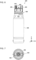
- FIG. 6 is a front view of the ink replenishment container 200 in a normal placement state
- FIG. 7 is a plan view of the ink replenishment container 200 in the normal placement state.
- the "normal placement state of the ink replenishment container 200" means a state in which a bottom of the container main body 300 is placed to face down on a horizontal surface such as a desk.
- ink is replenished to the ink tank 700 in an inverted posture with the tip side of the ink replenishment container 200 facing downward.
- FIGS. 6 and 7 illustrate a state in which the cap 600 is separated.
- FIG. 8 is a perspective view of the ink tank 700 according to the first embodiment.
- the ink inlet flow path member 710 of the ink tank 700 projects upward from the ink tank 700.
- the ink inlet flow path member 710 has two flow paths 711 and 712.
- the two flow paths 711 and 712 are divided by the partition wall 714.
- a tip surface of the ink inlet flow path member 710 is flat, and the two flow paths 711 and 712 are opened at the tip surface of the ink inlet flow path member 710, respectively. Further, a part of the tip surface of the ink inlet flow path member 710 corresponds to an end portion of the partition wall 714.
- the fitting portion 450 of the ink replenishment container 200 is fitted into the recess portion 750 around the ink inlet flow path member 710 of the ink tank 700, and the ink replenishment container 200 is positioned in a circumferential direction. Therefore, the two flow paths 711 and 712 communicate with two in-tank flow paths 721 and 722 projecting into a lower ink storage chamber 760, respectively. Lower ends of these in-tank flow paths 721 and 722 extend below a ceiling wall of the ink storage chamber 760.
- FIG. 9 is a cross-sectional view illustrating a replenishment state in which ink is replenished from the ink replenishment container 200 to the ink tank 700.
- the ink replenishment container 200 has an inverted posture, and a direction on the tip side of the ink replenishment container 200 is a tip side direction D1.
- the tubular portion 420 has a flange portion Fr extending in the radial direction of the ink outlet 460 that can come into contact with a tip of the outlet valve unit 500 in the axial direction, an engagement projection Kt extending from the flange portion Fr toward the inside of the tubular portion 420 in the axial direction, and an annular projection portion Co that can be engaged with an annular projection portion Co2 which is an engaging portion provided at the outer periphery of the outlet valve unit 500.
- the engagement projection Kt and the annular projection portion Co form a tubular portion side engaging portion.
- FIG. 9 only a part of each of the ink replenishment container 200 and the ink tank 700 is illustrated.
- the ink inlet flow path member 710 of the ink tank 700 is inserted into the tubular flow path portion 410 via the opening of the sealing member 510.
- a flow path (also referred to as "replenishment flow path") on the inner peripheral surface side of the tubular portion 420 than a center of the tubular flow path portion 410 in the radial direction is divided into two replenishment flow paths 411 and 412 formed in a gap between the valve housing 517 and an inner peripheral surface of the tubular portion 420.
- the gap forming the replenishment flow paths 411 and 412 also includes a gap via the through-hole Ho between the valve body 520 and the spring member 530 accommodated in the valve housing 517 and the inner peripheral surface of the tubular portion 420.
- the gap can be said to be a gap via the through-hole Ho between the outlet valve unit 500 and the inner peripheral surface of the tubular portion 420.
- one of the two replenishment flow paths 411 and 412 is used as a flow path of ink, and the other is used as a flow path of air.
- the ink replenishment container 200 can replenish the ink while the air-liquid exchange is performed with the ink tank 700.
- the ink replenishment is performed by using the air-liquid exchange, it is not necessary to squeeze the container main body 300.
- a type of ink replenishment container capable of ink replenishment without squeezing the container main body 300 is also referred to as a "non-squeeze type".
- the flow path of the tubular flow path portion 410 does not need to be divided into the two replenishment flow paths 411 and 412 via the flow paths 711 and 712 of the ink inlet flow path member 710 and the through-holes Ho of the valve housing 517, and may be formed as one replenishment flow path. Further, the flow path of the tubular flow path portion 410 may be divided into three or more replenishment flow paths.
- the outlet valve unit 500 is configured such that in the replenishment state, the replenishment flow paths 411 and 412 on the inner peripheral surface side of the tubular portion 420 than the center of the tubular flow path portion 410 in the radial direction communicate with the two flow paths 711 and 712 of the ink inlet flow path member 710.
- the replenishment flow paths 411 and 412 and the two flow paths 711 and 712 it is necessary to be in the "valve open state" so that the air and liquid can be passed through the through-hole Ho.
- the projection portion 526 of the valve body 520 is provided at a position facing the partition wall 714 of the ink inlet flow path member 710 in the axial direction.
- the projection portion 526 of the valve body 520 is pushed by the ink inlet flow path member 710 and retracts toward the container main body 300 side, and the two flow paths 711 and 712 of the ink inlet flow path member 710 respectively communicate with the replenishment flow paths 411 and 412 on the inner peripheral surface side of the tubular portion 420 than the center of the tubular flow path portion 410 in the radial direction through the through-hole Ho.
- Such a state is the "valve open state" described above.
- ink in the container main body 300 flows into the ink inlet flow path member 710 via the replenishment flow paths 411 and 412.
- solid arrows indicate a flow of the ink
- dashed arrows indicate a flow of the air.
- the two flow paths 711 and 712 of the ink inlet flow path member 710 and the two replenishment flow paths 411 and 412 of the tubular flow path portion 410 are used to efficiently replenish ink from the ink replenishment container 200 to the ink tank 700 while performing the air-liquid exchange.
- the replenishment flow path of the tubular flow path portion 410 is divided into a plurality of replenishment flow paths.
- one or more of a plurality of replenishment flow paths communicate with one or more of a plurality of ink inlet flow paths, and the other one or more of the plurality of replenishment flow paths communicate with the other one or more of the plurality of ink inlet flow paths.
- the projection portion 526 is formed such that a cross-sectional area in an orthogonal direction orthogonal to the axial direction on the rear end side is larger than the cross-sectional area on the tip side having the partition contact portion 526A in the axial direction. Therefore, since the cross-sectional area on a side in contact with the partition wall 714 is smaller than the cross-sectional area on a rear end side, it is difficult to obstruct the inflow of the ink and the outflow of the air through a plurality of flow paths, and it is possible to smoothly perform the air-liquid exchange. Further, since the rear end side becomes thicker, a strength when the projection portion 526 of the valve body 520 comes into contact with the partition wall 714 can be maintained, and the partition function can be appropriately maintained.
- the projection portion 526 of the valve body 520 has an inclined surface 526B enlarged from the tip side to the rear end side. Therefore, since the gas and the liquid flow along the inclined surface 526B, mutual interference is reduced, so the liquid can be quickly replenished by smoothly performing the air-liquid exchange.
- valve housing 517 on the rear end side is closed. Therefore, it is possible to prevent interference between the air and the liquid, smoothly perform the air-liquid exchange, and quickly replenish the ink.
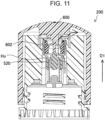
- FIG. 10 is a cross-sectional view of the ink replenishment container 200 when the cap 600 is closed.
- FIG. 11 is a cross-sectional view of the ink replenishment container 200 in the middle of opening the cap 600.
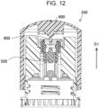
- FIG. 12 is a cross-sectional view of the ink replenishment container 200 when the cap 600 is fully opened.
- An arrow in the ink replenishment container 200 illustrated in FIG. 11 indicates a flow when the atmosphere is open.
- the cap 600 has a projection 602. As illustrated in FIG. 10 , in a state in which the cap 600 is closed, the projection 602 presses the valve body 520 toward the rear end side in the axial direction, so the valve open state is obtained.
- the through-hole Ho is generated, and the through-hole Ho and each of the replenishment flow paths 411 and 412 communicate with each other. Since the cap 600 is closed, the atmosphere is not open. Meanwhile, the replenishment flow paths 411 and 412 communicate with the inside of the sealing member 510 in the diameter direction, via the through-hole Ho.
- the valve body 520 moves toward the tip side in the axial direction and a length of the through-hole Ho in the axial direction is shortened, and when the cap is opened, the atmosphere is opened and an internal pressure is lowered.
- the valve body 520 further moves in the tip side direction D1 and the through-hole Ho is closed, so the valve close state is obtained.
- the ink does not leak.
- the cap 600 when the internal pressure of the ink replenishment container 200 is increased by a change in temperature or atmospheric pressure, the internal pressure is released when the opening of the cap 600 from the closed state, so that the ink jet can be prevented.
- ink in the container main body 300 passes through the through-hole Ho through the gap and flows into the other one of the plurality of flow paths. Therefore, the air and the liquid are more appropriately separated and the liquid can be quickly replenished by smooth air-liquid exchange, as compared with a configuration in which the air and the liquid pass through the valve housing 517.
- the projection portion 526 of the valve body 520 comes into contact with the partition wall 714 of the ink inlet flow path member 710, so that the sealing member 510 and the valve body 520 are separated from each other, and the gap of the sealing member 510 and the valve body 520 communicates with the through-hole Ho of the valve housing 517.
- the replenishment flow paths 411 and 412 which are formed as a gap between the valve housing 517 and the inner peripheral surface of the tubular portion 420 in the tubular flow path portion 410 via the through-hole Ho, are configured to communicate with the flow paths 711 and 712 of the ink inlet flow path member 710.
- the sealing member 510 is in contact with the outer peripheral surface of the ink inlet flow path member 710, and seals an outer peripheral surface of the ink inlet flow path member 710.
- the cross-sectional area on a side in contact with the partition wall 714 is smaller than the cross-sectional area on a rear end side, it is difficult to obstruct the inflow of the ink and the outflow of the air through the plurality of flow paths, and it is possible to smoothly perform the air-liquid exchange. Further, since the rear end side becomes thicker, a strength when the projection portion 526 of the valve body 520 comes into contact with the partition wall 714 can be maintained, and the partition function can be appropriately maintained.
- valve housing 517 since the rear end side of the valve housing 517 is closed, interference between air and liquid can be prevented, air-liquid exchange can be smoothly performed, and the ink can be quickly replenished.
- valve body 520 has the cylindrical portion 524 facing the inner surface of the valve housing 517.
- the cylindrical portion 524 is configured to be slidable by being guided by the inner surface of the valve housing 517. Therefore, an opening and closing operation of the valve body 520 is appropriately performed.
- the cap 600 capable of covering the ink outlet 460 is provided, and the cap 600 has the projection 602 that presses the valve body 520 in a state in which the cap 600 closed to obtain the valve open state. Therefore, when the internal pressure of the ink replenishment container 200 is increased by a change in temperature or atmospheric pressure, the internal pressure is released when the opening of the cap 600 from the closed state, so that the ink jet can be prevented.
- valve housing 517 has the retaining portion 517A of the sealing member 510 on the tip side and the engaging portion 517B with the tubular portion 420, and is detachably configured in the tubular portion 420. Therefore, the outlet valve unit 500 is integrated in a state of being assembled with the tubular portion 420.
- the outlet valve unit 500 is detachable by itself, it is easy to manufacture or handle the outlet valve unit 500, and the outlet valve unit 500 can be transported by itself, and the outlet valve unit 500 can be replaced when the ink replenishment container 200 is reused.
- the sealing member 510 is suppressed from falling off, the sealing member 510 can be reliably accommodated in the valve housing 517, and a positional relationship with the valve body is appropriately maintained. Further, since a separate stopper member may not be mounted, it is possible to suppress an increase in components or an increase in manufacturing steps.
- the "partition wall 714" in the first embodiment corresponds to the "partition" of the present disclosure.
- the ink replenishment container 200 includes the outlet valve unit 500, which is a spring valve unit including the spring member 530 housed in the valve housing 517 of the tubular portion 420, and the present disclosure is not limited to this.
- the ink replenishment container 200 may include an outlet valve unit provided with a slit valve, instead of the outlet valve unit 500, which is a spring valve unit.
- the ink replenishment container 200 may be configured such that an outlet valve unit having an engaging portion capable of engaging with each of the engagement projection Kt of the tubular portion 420 and the annular projection portion Co, which is an outlet valve unit provided with a slit valve having a slit through which the ink inlet flow path member 710 can be inserted and removed in the diameter direction of the valve body 520, can be replaced with the spring valve unit. Therefore, when the supply of the outlet valve unit becomes insufficient, the outlet valve unit can be replaced with the slit valve unit, the other parts of the ink outlet forming portion 400 are commonized, and manufacturing or maintenance is facilitated. Further, when the ink replenishment container 200 is reused, it is possible to easily change the spring valve unit to be detached and the slit valve unit to be attached, or the slit valve unit to be detached and the spring valve unit to be attached.
- the ink replenishment container 200 includes the cap 600, and the cap 600 may not be provided.
- valve housing 517 is detachably configured in the tubular portion 420, and may be integrated without being detachable.
Landscapes
- Ink Jet (AREA)
Claims (8)
- Tintennachfüllbehälter (200) zum Nachfüllen von Tinte in einen Tintentank (700) eines Druckers (100) über ein Tinteneinlasströmungspfadelement (710) des Tintentanks, wobei das Tinteneinlasströmungspfadelement mehrere Strömungspfade aufweist, die durch eine Trennwand (714) getrennt sind, wobei der Tintennachfüllbehälter umfasst:einen Behälterhauptkörper (300), der eingerichtet ist, die Tinte aufzunehmen;einen Tintenauslassbildungsabschnitt (400), der an den Behälterhauptkörper gekoppelt ist und einen rohrförmigen Abschnitt (420) enthält, der einen Tintenauslass (460) aufweist; undeine Auslassventileinheit (500), die in dem rohrförmigen Abschnitt montiert ist,wobei die Auslassventileinheit enthältein Ventilgehäuse (517), das montiert ist, um einen Spalt mit einer Innenumfangsfläche des rohrförmigen Abschnitts in dem rohrförmigen Abschnitt bereitzustellen,ein Dichtungselement (510), das in dem Ventilgehäuse montiert ist und eine Öffnung aufweist, durch die das Tinteneinlasströmungspfadelement eingesetzt und entfernt wird, undeinen Ventilkörper (520), der in dem Ventilgehäuse montiert ist, um in einer Richtung einer Mittelachse (C) des Tintenauslasses beweglich zu sein und zwischen einem geschlossenen Zustand des Ventils, in dem der Ventilkörper mit dem Dichtungselement in Kontakt ist, und einem offenen Zustand des Ventils, in dem der Ventilkörper von dem Tinteneinlasströmungspfadelement gepresst wird und von dem Dichtungselement getrennt ist, beweglich zu sein,der Ventilkörper einen Trennkontaktabschnitt (526A) mit einer Stirnfläche enthält, die eingerichtet ist, mit der Trennwand (714) des Tinteneinlasströmungspfadelements in Kontakt zu sein, unddas Ventilgehäuse (517) ein Durchgangsloch (Ho) enthält, das mit dem Spalt kommuniziert, und das Durchgangsloch mit dem Tinteneinlasströmungspfadelement (710) im offenen Zustand des Ventils kommuniziert.
- Tintennachfüllbehälter (200) nach Anspruch 1,
wobei der Trennkontaktabschnitt (526A) des Ventilkörpers (520) an einem Vorsprungsabschnitt (526) bereitgestellt ist, der in dem Ventilkörper enthalten ist, und der Vorsprungsabschnitt so gebildet ist, dass eine Querschnittsfläche in einer Richtung orthogonal zu der Richtung der Mittelachse (C) an einer hinteren Endseite größer ist als eine Querschnittsfläche an einer Spitzenseite, die den Trennkontaktabschnitt aufweist. - Tintennachfüllbehälter (200) nach Anspruch 2,
wobei der Vorsprungsabschnitt (526) des Ventilkörpers (520) eine Schrägfläche aufweist, die von der Spitzenseite zu der hinteren Endseite vergrößert ist. - Tintennachfüllbehälter (200) nach Anspruch 1,
wobei ein mittiger Abschnitt des Ventilgehäuses (517) an einer hinteren Endseite geschlossen ist. - Tintennachfüllbehälter (200) nach Anspruch 1,
wobei der Ventilkörper (520) einen zylinderförmigen Abschnitt (524) aufweist, der einer Innenfläche des Ventilgehäuses (517) zugewandt ist, und der zylinderförmige Abschnitt eingerichtet ist, von der Innenfläche geführt und verschoben zu werden. - Tintennachfüllbehälter (200) nach Anspruch 1,
wobei die Auslassventileinheit (500) ein Federelement (530) enthält, das in dem Ventilgehäuse (517) untergebracht ist und gehalten wird, und das Federelement im geschlossenen Zustand des Ventils den Ventilkörper (520) zu dem Dichtungselement (510) spannt. - Tintennachfüllbehälter (200) nach Anspruch 1,
wobei das Ventilgehäuse (517) einen Rückhalteabschnitt des Dichtungselements (510) aufweist. - Tintennachfüllbehälter (200) nach Anspruch 1, weiter umfassend:einen Deckel (600), der eingerichtet ist, den Tintenauslass (460) zu bedecken,wobei der Deckel einen Vorsprung (602) aufweist, der den Ventilkörper (520) in einem Zustand presst, in dem der Deckel geschlossen ist, um den offenen Zustand des Ventils zu erhalten.
Applications Claiming Priority (1)
| Application Number | Priority Date | Filing Date | Title |
|---|---|---|---|
| JP2021151637A JP7690828B2 (ja) | 2021-09-17 | 2021-09-17 | インク補給容器 |
Publications (2)
| Publication Number | Publication Date |
|---|---|
| EP4151419A1 EP4151419A1 (de) | 2023-03-22 |
| EP4151419B1 true EP4151419B1 (de) | 2025-02-12 |
Family
ID=83361017
Family Applications (1)
| Application Number | Title | Priority Date | Filing Date |
|---|---|---|---|
| EP22196039.6A Active EP4151419B1 (de) | 2021-09-17 | 2022-09-16 | Tintennachfüllbehälter |
Country Status (4)
| Country | Link |
|---|---|
| US (1) | US12103312B2 (de) |
| EP (1) | EP4151419B1 (de) |
| JP (1) | JP7690828B2 (de) |
| CN (1) | CN115817022A (de) |
Families Citing this family (2)
| Publication number | Priority date | Publication date | Assignee | Title |
|---|---|---|---|---|
| WO2020106278A1 (en) * | 2018-11-20 | 2020-05-28 | Hewlett-Packard Development Company, L.P. | Fluid supply valve |
| CN221022892U (zh) * | 2023-09-19 | 2024-05-28 | 珠海纳思达企业管理有限公司 | 一种墨水补充容器 |
Family Cites Families (23)
| Publication number | Priority date | Publication date | Assignee | Title |
|---|---|---|---|---|
| JPH0966959A (ja) | 1995-08-30 | 1997-03-11 | Lion Corp | 注出中栓容器 |
| US6079823A (en) | 1997-07-23 | 2000-06-27 | Marconi Data Systems Inc. | Ink bottle with puncturable diaphragm closure |
| US6164768A (en) * | 1999-11-09 | 2000-12-26 | Illinois Tool Works Inc. | Adapter and mating bottle cap for coupling bottles to ink supplies |
| US6969161B2 (en) | 2002-09-30 | 2005-11-29 | Canon Kabushiki Kaisha | Ink supply system, ink jet printing apparatus, ink container, ink refilling container and ink jet cartridge |
| JP4506301B2 (ja) * | 2003-09-30 | 2010-07-21 | ブラザー工業株式会社 | インクカートリッジ及びインクジェットプリンタ |
| JP6016707B2 (ja) | 2013-04-26 | 2016-10-26 | 京セラドキュメントソリューションズ株式会社 | 液体容器およびこれを備えたインクジェット式画像形成装置 |
| JP6919232B2 (ja) | 2017-03-01 | 2021-08-18 | セイコーエプソン株式会社 | インク補給容器 |
| CN207291315U (zh) | 2016-06-10 | 2018-05-01 | 精工爱普生株式会社 | 墨水补充容器和墨水补充系统 |
| KR102225720B1 (ko) | 2016-06-10 | 2021-03-09 | 세이코 엡슨 가부시키가이샤 | 잉크 보급 용기, 잉크 보급 시스템 및 잉크 보급용 어댑터 |
| US10350901B2 (en) * | 2016-06-10 | 2019-07-16 | Seiko Epson Corporation | Ink bottle |
| JP2018144239A (ja) * | 2017-03-01 | 2018-09-20 | セイコーエプソン株式会社 | プリンター、インクボトル |
| JP6922258B2 (ja) | 2017-03-02 | 2021-08-18 | セイコーエプソン株式会社 | インク補給容器及びインク補給システム |
| JP2018149785A (ja) | 2017-03-15 | 2018-09-27 | セイコーエプソン株式会社 | インク補給容器 |
| CN208180537U (zh) | 2017-03-27 | 2018-12-04 | 精工爱普生株式会社 | 墨水补给辅助装置以及墨水补给装置 |
| JP7292929B2 (ja) | 2018-04-27 | 2023-06-19 | キヤノン株式会社 | 収納容器の製造方法および内層の剥離方法 |
| JP2019055604A (ja) | 2019-01-22 | 2019-04-11 | セイコーエプソン株式会社 | インク補給容器 |
| JP7183810B2 (ja) * | 2019-01-24 | 2022-12-06 | セイコーエプソン株式会社 | インク補給容器およびインク補給システム |
| JP7163790B2 (ja) * | 2019-01-24 | 2022-11-01 | セイコーエプソン株式会社 | インク補給容器およびインク補給システム |
| JP7282571B2 (ja) | 2019-03-29 | 2023-05-29 | キヤノン株式会社 | 液体収容ボトル |
| JP7500218B2 (ja) | 2020-02-19 | 2024-06-17 | キヤノン株式会社 | 液体収容ボトル |
| JP7475890B2 (ja) | 2020-02-20 | 2024-04-30 | キヤノン株式会社 | 液体補給容器 |
| JP7201636B2 (ja) | 2020-03-24 | 2023-01-10 | 大阪ガスリキッド株式会社 | 凍結体製造装置 |
| JP7500313B2 (ja) | 2020-07-16 | 2024-06-17 | キヤノン株式会社 | インク収容容器 |
-
2021
- 2021-09-17 JP JP2021151637A patent/JP7690828B2/ja active Active
-
2022
- 2022-09-14 CN CN202211116021.0A patent/CN115817022A/zh active Pending
- 2022-09-16 US US17/946,397 patent/US12103312B2/en active Active
- 2022-09-16 EP EP22196039.6A patent/EP4151419B1/de active Active
Also Published As
| Publication number | Publication date |
|---|---|
| US20230088212A1 (en) | 2023-03-23 |
| EP4151419A1 (de) | 2023-03-22 |
| JP2023043905A (ja) | 2023-03-30 |
| JP7690828B2 (ja) | 2025-06-11 |
| US12103312B2 (en) | 2024-10-01 |
| CN115817022A (zh) | 2023-03-21 |
Similar Documents
| Publication | Publication Date | Title |
|---|---|---|
| JP7147198B2 (ja) | インク補給補助装置及びインク補給装置 | |
| CN108528052B (zh) | 墨水补给容器 | |
| CN113942311B (zh) | 液体储存容器 | |
| EP4151419B1 (de) | Tintennachfüllbehälter | |
| CN113942309B (zh) | 液体储存容器 | |
| CN113942310A (zh) | 液体存储容器 | |
| JP2025065520A (ja) | 印刷用液体容器 | |
| US7354143B2 (en) | Inkjet recording apparatus | |
| US7597433B2 (en) | Ink cartridge, inkjet printer and combination thereof | |
| JP7306058B2 (ja) | 印刷用液体容器、システム、及びキャップ | |
| JP7516625B2 (ja) | 液体吐出装置 | |
| US12172447B2 (en) | Ink replenishment container | |
| US20260054489A1 (en) | Ink replenishment container | |
| JP2023051714A (ja) | インク補給容器 | |
| US20240383254A1 (en) | Ink refill container | |
| JP2024115109A (ja) | インク補給容器 | |
| JP7757716B2 (ja) | インク補給容器 | |
| CN121697351A (zh) | 墨水补给容器 | |
| JP2026055630A (ja) | インク補給容器 | |
| JP2026037584A (ja) | インク補給容器 | |
| US20260008271A1 (en) | Ink replenishment container | |
| JP2026048345A (ja) | インク補給容器 | |
| CN119189510A (zh) | 液体补给容器 | |
| JP4296445B2 (ja) | インクカートリッジ |
Legal Events
| Date | Code | Title | Description |
|---|---|---|---|
| PUAI | Public reference made under article 153(3) epc to a published international application that has entered the european phase |
Free format text: ORIGINAL CODE: 0009012 |
|
| STAA | Information on the status of an ep patent application or granted ep patent |
Free format text: STATUS: THE APPLICATION HAS BEEN PUBLISHED |
|
| AK | Designated contracting states |
Kind code of ref document: A1 Designated state(s): AL AT BE BG CH CY CZ DE DK EE ES FI FR GB GR HR HU IE IS IT LI LT LU LV MC MK MT NL NO PL PT RO RS SE SI SK SM TR |
|
| STAA | Information on the status of an ep patent application or granted ep patent |
Free format text: STATUS: REQUEST FOR EXAMINATION WAS MADE |
|
| 17P | Request for examination filed |
Effective date: 20230918 |
|
| RBV | Designated contracting states (corrected) |
Designated state(s): AL AT BE BG CH CY CZ DE DK EE ES FI FR GB GR HR HU IE IS IT LI LT LU LV MC MK MT NL NO PL PT RO RS SE SI SK SM TR |
|
| GRAP | Despatch of communication of intention to grant a patent |
Free format text: ORIGINAL CODE: EPIDOSNIGR1 |
|
| STAA | Information on the status of an ep patent application or granted ep patent |
Free format text: STATUS: GRANT OF PATENT IS INTENDED |
|
| RIC1 | Information provided on ipc code assigned before grant |
Ipc: B67D 3/02 20060101ALI20240829BHEP Ipc: B65D 47/24 20060101ALI20240829BHEP Ipc: B65D 1/02 20060101ALI20240829BHEP Ipc: B41J 2/175 20060101AFI20240829BHEP |
|
| INTG | Intention to grant announced |
Effective date: 20240916 |
|
| GRAS | Grant fee paid |
Free format text: ORIGINAL CODE: EPIDOSNIGR3 |
|
| GRAA | (expected) grant |
Free format text: ORIGINAL CODE: 0009210 |
|
| STAA | Information on the status of an ep patent application or granted ep patent |
Free format text: STATUS: THE PATENT HAS BEEN GRANTED |
|
| AK | Designated contracting states |
Kind code of ref document: B1 Designated state(s): AL AT BE BG CH CY CZ DE DK EE ES FI FR GB GR HR HU IE IS IT LI LT LU LV MC MK MT NL NO PL PT RO RS SE SI SK SM TR |
|
| REG | Reference to a national code |
Ref country code: GB Ref legal event code: FG4D |
|
| REG | Reference to a national code |
Ref country code: CH Ref legal event code: EP |
|
| REG | Reference to a national code |
Ref country code: DE Ref legal event code: R096 Ref document number: 602022010430 Country of ref document: DE |
|
| REG | Reference to a national code |
Ref country code: IE Ref legal event code: FG4D |
|
| REG | Reference to a national code |
Ref country code: NL Ref legal event code: MP Effective date: 20250212 |
|
| PG25 | Lapsed in a contracting state [announced via postgrant information from national office to epo] |
Ref country code: RS Free format text: LAPSE BECAUSE OF FAILURE TO SUBMIT A TRANSLATION OF THE DESCRIPTION OR TO PAY THE FEE WITHIN THE PRESCRIBED TIME-LIMIT Effective date: 20250512 |
|
| PG25 | Lapsed in a contracting state [announced via postgrant information from national office to epo] |
Ref country code: FI Free format text: LAPSE BECAUSE OF FAILURE TO SUBMIT A TRANSLATION OF THE DESCRIPTION OR TO PAY THE FEE WITHIN THE PRESCRIBED TIME-LIMIT Effective date: 20250212 |
|
| PG25 | Lapsed in a contracting state [announced via postgrant information from national office to epo] |
Ref country code: PL Free format text: LAPSE BECAUSE OF FAILURE TO SUBMIT A TRANSLATION OF THE DESCRIPTION OR TO PAY THE FEE WITHIN THE PRESCRIBED TIME-LIMIT Effective date: 20250212 |
|
| PG25 | Lapsed in a contracting state [announced via postgrant information from national office to epo] |
Ref country code: ES Free format text: LAPSE BECAUSE OF FAILURE TO SUBMIT A TRANSLATION OF THE DESCRIPTION OR TO PAY THE FEE WITHIN THE PRESCRIBED TIME-LIMIT Effective date: 20250212 |
|
| REG | Reference to a national code |
Ref country code: LT Ref legal event code: MG9D |
|
| PG25 | Lapsed in a contracting state [announced via postgrant information from national office to epo] |
Ref country code: IS Free format text: LAPSE BECAUSE OF FAILURE TO SUBMIT A TRANSLATION OF THE DESCRIPTION OR TO PAY THE FEE WITHIN THE PRESCRIBED TIME-LIMIT Effective date: 20250612 Ref country code: NO Free format text: LAPSE BECAUSE OF FAILURE TO SUBMIT A TRANSLATION OF THE DESCRIPTION OR TO PAY THE FEE WITHIN THE PRESCRIBED TIME-LIMIT Effective date: 20250512 |
|
| PG25 | Lapsed in a contracting state [announced via postgrant information from national office to epo] |
Ref country code: NL Free format text: LAPSE BECAUSE OF FAILURE TO SUBMIT A TRANSLATION OF THE DESCRIPTION OR TO PAY THE FEE WITHIN THE PRESCRIBED TIME-LIMIT Effective date: 20250212 |
|
| PG25 | Lapsed in a contracting state [announced via postgrant information from national office to epo] |
Ref country code: HR Free format text: LAPSE BECAUSE OF FAILURE TO SUBMIT A TRANSLATION OF THE DESCRIPTION OR TO PAY THE FEE WITHIN THE PRESCRIBED TIME-LIMIT Effective date: 20250212 |
|
| PG25 | Lapsed in a contracting state [announced via postgrant information from national office to epo] |
Ref country code: LV Free format text: LAPSE BECAUSE OF FAILURE TO SUBMIT A TRANSLATION OF THE DESCRIPTION OR TO PAY THE FEE WITHIN THE PRESCRIBED TIME-LIMIT Effective date: 20250212 Ref country code: PT Free format text: LAPSE BECAUSE OF FAILURE TO SUBMIT A TRANSLATION OF THE DESCRIPTION OR TO PAY THE FEE WITHIN THE PRESCRIBED TIME-LIMIT Effective date: 20250612 |
|
| PG25 | Lapsed in a contracting state [announced via postgrant information from national office to epo] |
Ref country code: GR Free format text: LAPSE BECAUSE OF FAILURE TO SUBMIT A TRANSLATION OF THE DESCRIPTION OR TO PAY THE FEE WITHIN THE PRESCRIBED TIME-LIMIT Effective date: 20250513 Ref country code: BG Free format text: LAPSE BECAUSE OF FAILURE TO SUBMIT A TRANSLATION OF THE DESCRIPTION OR TO PAY THE FEE WITHIN THE PRESCRIBED TIME-LIMIT Effective date: 20250212 |
|
| REG | Reference to a national code |
Ref country code: AT Ref legal event code: MK05 Ref document number: 1765748 Country of ref document: AT Kind code of ref document: T Effective date: 20250212 |
|
| PG25 | Lapsed in a contracting state [announced via postgrant information from national office to epo] |
Ref country code: SE Free format text: LAPSE BECAUSE OF FAILURE TO SUBMIT A TRANSLATION OF THE DESCRIPTION OR TO PAY THE FEE WITHIN THE PRESCRIBED TIME-LIMIT Effective date: 20250212 |
|
| PG25 | Lapsed in a contracting state [announced via postgrant information from national office to epo] |
Ref country code: SM Free format text: LAPSE BECAUSE OF FAILURE TO SUBMIT A TRANSLATION OF THE DESCRIPTION OR TO PAY THE FEE WITHIN THE PRESCRIBED TIME-LIMIT Effective date: 20250212 |
|
| PG25 | Lapsed in a contracting state [announced via postgrant information from national office to epo] |
Ref country code: DK Free format text: LAPSE BECAUSE OF FAILURE TO SUBMIT A TRANSLATION OF THE DESCRIPTION OR TO PAY THE FEE WITHIN THE PRESCRIBED TIME-LIMIT Effective date: 20250212 |
|
| PGFP | Annual fee paid to national office [announced via postgrant information from national office to epo] |
Ref country code: DE Payment date: 20250926 Year of fee payment: 4 |
|
| PG25 | Lapsed in a contracting state [announced via postgrant information from national office to epo] |
Ref country code: IT Free format text: LAPSE BECAUSE OF FAILURE TO SUBMIT A TRANSLATION OF THE DESCRIPTION OR TO PAY THE FEE WITHIN THE PRESCRIBED TIME-LIMIT Effective date: 20250212 |
|
| PG25 | Lapsed in a contracting state [announced via postgrant information from national office to epo] |
Ref country code: AT Free format text: LAPSE BECAUSE OF FAILURE TO SUBMIT A TRANSLATION OF THE DESCRIPTION OR TO PAY THE FEE WITHIN THE PRESCRIBED TIME-LIMIT Effective date: 20250212 |
|
| PGFP | Annual fee paid to national office [announced via postgrant information from national office to epo] |
Ref country code: FR Payment date: 20250925 Year of fee payment: 4 |
|
| PG25 | Lapsed in a contracting state [announced via postgrant information from national office to epo] |
Ref country code: EE Free format text: LAPSE BECAUSE OF FAILURE TO SUBMIT A TRANSLATION OF THE DESCRIPTION OR TO PAY THE FEE WITHIN THE PRESCRIBED TIME-LIMIT Effective date: 20250212 Ref country code: CZ Free format text: LAPSE BECAUSE OF FAILURE TO SUBMIT A TRANSLATION OF THE DESCRIPTION OR TO PAY THE FEE WITHIN THE PRESCRIBED TIME-LIMIT Effective date: 20250212 |
|
| PG25 | Lapsed in a contracting state [announced via postgrant information from national office to epo] |
Ref country code: RO Free format text: LAPSE BECAUSE OF FAILURE TO SUBMIT A TRANSLATION OF THE DESCRIPTION OR TO PAY THE FEE WITHIN THE PRESCRIBED TIME-LIMIT Effective date: 20250212 |
|
| PG25 | Lapsed in a contracting state [announced via postgrant information from national office to epo] |
Ref country code: SK Free format text: LAPSE BECAUSE OF FAILURE TO SUBMIT A TRANSLATION OF THE DESCRIPTION OR TO PAY THE FEE WITHIN THE PRESCRIBED TIME-LIMIT Effective date: 20250212 |
|
| REG | Reference to a national code |
Ref country code: DE Ref legal event code: R097 Ref document number: 602022010430 Country of ref document: DE |
|
| PLBE | No opposition filed within time limit |
Free format text: ORIGINAL CODE: 0009261 |
|
| STAA | Information on the status of an ep patent application or granted ep patent |
Free format text: STATUS: NO OPPOSITION FILED WITHIN TIME LIMIT |
|
| 26N | No opposition filed |
Effective date: 20251113 |