EP1566535A2 - Récipient de rétention des gaz - Google Patents
Récipient de rétention des gaz Download PDFInfo
- Publication number
- EP1566535A2 EP1566535A2 EP05003678A EP05003678A EP1566535A2 EP 1566535 A2 EP1566535 A2 EP 1566535A2 EP 05003678 A EP05003678 A EP 05003678A EP 05003678 A EP05003678 A EP 05003678A EP 1566535 A2 EP1566535 A2 EP 1566535A2
- Authority
- EP
- European Patent Office
- Prior art keywords
- heat accumulative
- storage canister
- gas
- heat
- gas adsorbing
- Prior art date
- Legal status (The legal status is an assumption and is not a legal conclusion. Google has not performed a legal analysis and makes no representation as to the accuracy of the status listed.)
- Withdrawn
Links
- 238000003860 storage Methods 0.000 title claims abstract description 66
- 239000000463 material Substances 0.000 claims abstract description 170
- 239000003795 chemical substances by application Substances 0.000 claims abstract description 38
- 239000003094 microcapsule Substances 0.000 claims abstract description 32
- 238000001179 sorption measurement Methods 0.000 claims abstract description 21
- 239000011230 binding agent Substances 0.000 claims abstract description 18
- OKTJSMMVPCPJKN-UHFFFAOYSA-N Carbon Chemical compound [C] OKTJSMMVPCPJKN-UHFFFAOYSA-N 0.000 claims description 55
- 238000000034 method Methods 0.000 claims description 14
- 239000012782 phase change material Substances 0.000 claims description 14
- 239000002245 particle Substances 0.000 claims description 12
- 229920005989 resin Polymers 0.000 claims description 7
- 239000011347 resin Substances 0.000 claims description 7
- 239000008187 granular material Substances 0.000 claims description 5
- 238000002156 mixing Methods 0.000 claims description 5
- 230000008018 melting Effects 0.000 claims description 3
- 238000002844 melting Methods 0.000 claims description 3
- 229920001187 thermosetting polymer Polymers 0.000 claims description 3
- 239000011358 absorbing material Substances 0.000 claims description 2
- 150000001875 compounds Chemical class 0.000 claims description 2
- 238000011049 filling Methods 0.000 claims description 2
- 239000000446 fuel Substances 0.000 abstract description 38
- 238000002485 combustion reaction Methods 0.000 abstract description 3
- 239000007789 gas Substances 0.000 description 134
- 239000000203 mixture Substances 0.000 description 26
- 230000000052 comparative effect Effects 0.000 description 14
- 238000012360 testing method Methods 0.000 description 13
- CBFCDTFDPHXCNY-UHFFFAOYSA-N icosane Chemical compound CCCCCCCCCCCCCCCCCCCC CBFCDTFDPHXCNY-UHFFFAOYSA-N 0.000 description 8
- 239000000243 solution Substances 0.000 description 7
- 229920000877 Melamine resin Polymers 0.000 description 6
- 239000007864 aqueous solution Substances 0.000 description 6
- 230000000694 effects Effects 0.000 description 6
- 238000005538 encapsulation Methods 0.000 description 6
- 238000000926 separation method Methods 0.000 description 6
- 239000002023 wood Substances 0.000 description 6
- 229920002134 Carboxymethyl cellulose Polymers 0.000 description 4
- 239000004677 Nylon Substances 0.000 description 4
- 239000001768 carboxy methyl cellulose Substances 0.000 description 4
- 235000010948 carboxy methyl cellulose Nutrition 0.000 description 4
- 239000008112 carboxymethyl-cellulose Substances 0.000 description 4
- 238000001125 extrusion Methods 0.000 description 4
- JDSHMPZPIAZGSV-UHFFFAOYSA-N melamine Chemical compound NC1=NC(N)=NC(N)=N1 JDSHMPZPIAZGSV-UHFFFAOYSA-N 0.000 description 4
- 229920001778 nylon Polymers 0.000 description 4
- RZJRJXONCZWCBN-UHFFFAOYSA-N octadecane Chemical compound CCCCCCCCCCCCCCCCCC RZJRJXONCZWCBN-UHFFFAOYSA-N 0.000 description 4
- 239000002002 slurry Substances 0.000 description 4
- WSFSSNUMVMOOMR-UHFFFAOYSA-N Formaldehyde Chemical compound O=C WSFSSNUMVMOOMR-UHFFFAOYSA-N 0.000 description 3
- OKKJLVBELUTLKV-UHFFFAOYSA-N Methanol Chemical compound OC OKKJLVBELUTLKV-UHFFFAOYSA-N 0.000 description 3
- 238000006243 chemical reaction Methods 0.000 description 3
- 238000003795 desorption Methods 0.000 description 3
- 239000002904 solvent Substances 0.000 description 3
- FLIACVVOZYBSBS-UHFFFAOYSA-N Methyl palmitate Chemical compound CCCCCCCCCCCCCCCC(=O)OC FLIACVVOZYBSBS-UHFFFAOYSA-N 0.000 description 2
- HPEUJPJOZXNMSJ-UHFFFAOYSA-N Methyl stearate Chemical compound CCCCCCCCCCCCCCCCCC(=O)OC HPEUJPJOZXNMSJ-UHFFFAOYSA-N 0.000 description 2
- 230000015572 biosynthetic process Effects 0.000 description 2
- 239000007859 condensation product Substances 0.000 description 2
- GHVNFZFCNZKVNT-UHFFFAOYSA-N decanoic acid Chemical compound CCCCCCCCCC(O)=O GHVNFZFCNZKVNT-UHFFFAOYSA-N 0.000 description 2
- 230000003247 decreasing effect Effects 0.000 description 2
- HOWGUJZVBDQJKV-UHFFFAOYSA-N docosane Chemical compound CCCCCCCCCCCCCCCCCCCCCC HOWGUJZVBDQJKV-UHFFFAOYSA-N 0.000 description 2
- POULHZVOKOAJMA-UHFFFAOYSA-N dodecanoic acid Chemical compound CCCCCCCCCCCC(O)=O POULHZVOKOAJMA-UHFFFAOYSA-N 0.000 description 2
- IVJISJACKSSFGE-UHFFFAOYSA-N formaldehyde;1,3,5-triazine-2,4,6-triamine Chemical compound O=C.NC1=NC(N)=NC(N)=N1 IVJISJACKSSFGE-UHFFFAOYSA-N 0.000 description 2
- FNAZRRHPUDJQCJ-UHFFFAOYSA-N henicosane Chemical compound CCCCCCCCCCCCCCCCCCCCC FNAZRRHPUDJQCJ-UHFFFAOYSA-N 0.000 description 2
- NDJKXXJCMXVBJW-UHFFFAOYSA-N heptadecane Chemical compound CCCCCCCCCCCCCCCCC NDJKXXJCMXVBJW-UHFFFAOYSA-N 0.000 description 2
- DCAYPVUWAIABOU-UHFFFAOYSA-N hexadecane Chemical compound CCCCCCCCCCCCCCCC DCAYPVUWAIABOU-UHFFFAOYSA-N 0.000 description 2
- 150000002484 inorganic compounds Chemical class 0.000 description 2
- 229910010272 inorganic material Inorganic materials 0.000 description 2
- 239000007788 liquid Substances 0.000 description 2
- IIPYXGDZVMZOAP-UHFFFAOYSA-N lithium nitrate Chemical compound [Li+].[O-][N+]([O-])=O IIPYXGDZVMZOAP-UHFFFAOYSA-N 0.000 description 2
- VAMFXQBUQXONLZ-UHFFFAOYSA-N n-alpha-eicosene Natural products CCCCCCCCCCCCCCCCCCC=C VAMFXQBUQXONLZ-UHFFFAOYSA-N 0.000 description 2
- LQERIDTXQFOHKA-UHFFFAOYSA-N nonadecane Chemical compound CCCCCCCCCCCCCCCCCCC LQERIDTXQFOHKA-UHFFFAOYSA-N 0.000 description 2
- YCOZIPAWZNQLMR-UHFFFAOYSA-N pentadecane Chemical compound CCCCCCCCCCCCCCC YCOZIPAWZNQLMR-UHFFFAOYSA-N 0.000 description 2
- 239000002994 raw material Substances 0.000 description 2
- BGHCVCJVXZWKCC-UHFFFAOYSA-N tetradecane Chemical compound CCCCCCCCCCCCCC BGHCVCJVXZWKCC-UHFFFAOYSA-N 0.000 description 2
- XLYOFNOQVPJJNP-UHFFFAOYSA-N water Substances O XLYOFNOQVPJJNP-UHFFFAOYSA-N 0.000 description 2
- KXGFMDJXCMQABM-UHFFFAOYSA-N 2-methoxy-6-methylphenol Chemical compound [CH]OC1=CC=CC([CH])=C1O KXGFMDJXCMQABM-UHFFFAOYSA-N 0.000 description 1
- 229920000178 Acrylic resin Polymers 0.000 description 1
- 239000004925 Acrylic resin Substances 0.000 description 1
- 239000005632 Capric acid (CAS 334-48-5) Substances 0.000 description 1
- 108010010803 Gelatin Proteins 0.000 description 1
- 239000005639 Lauric acid Substances 0.000 description 1
- -1 LiNO3•3H2O Chemical class 0.000 description 1
- 239000007832 Na2SO4 Substances 0.000 description 1
- PMZURENOXWZQFD-UHFFFAOYSA-L Sodium Sulfate Chemical compound [Na+].[Na+].[O-]S([O-])(=O)=O PMZURENOXWZQFD-UHFFFAOYSA-L 0.000 description 1
- 150000001298 alcohols Chemical class 0.000 description 1
- 150000001338 aliphatic hydrocarbons Chemical class 0.000 description 1
- 239000000440 bentonite Substances 0.000 description 1
- 229910000278 bentonite Inorganic materials 0.000 description 1
- SVPXDRXYRYOSEX-UHFFFAOYSA-N bentoquatam Chemical compound O.O=[Si]=O.O=[Al]O[Al]=O SVPXDRXYRYOSEX-UHFFFAOYSA-N 0.000 description 1
- 230000005587 bubbling Effects 0.000 description 1
- 229910052799 carbon Inorganic materials 0.000 description 1
- 239000004927 clay Substances 0.000 description 1
- 238000005354 coacervation Methods 0.000 description 1
- 239000011248 coating agent Substances 0.000 description 1
- 238000000576 coating method Methods 0.000 description 1
- 238000004891 communication Methods 0.000 description 1
- 238000007796 conventional method Methods 0.000 description 1
- 229920001577 copolymer Polymers 0.000 description 1
- 239000011162 core material Substances 0.000 description 1
- 230000007423 decrease Effects 0.000 description 1
- 235000014113 dietary fatty acids Nutrition 0.000 description 1
- BNIILDVGGAEEIG-UHFFFAOYSA-L disodium hydrogen phosphate Chemical compound [Na+].[Na+].OP([O-])([O-])=O BNIILDVGGAEEIG-UHFFFAOYSA-L 0.000 description 1
- 229910000397 disodium phosphate Inorganic materials 0.000 description 1
- 238000004090 dissolution Methods 0.000 description 1
- 238000004945 emulsification Methods 0.000 description 1
- CAMHHLOGFDZBBG-UHFFFAOYSA-N epoxidized methyl oleate Natural products CCCCCCCCC1OC1CCCCCCCC(=O)OC CAMHHLOGFDZBBG-UHFFFAOYSA-N 0.000 description 1
- 150000002148 esters Chemical class 0.000 description 1
- 230000001747 exhibiting effect Effects 0.000 description 1
- 238000002474 experimental method Methods 0.000 description 1
- 239000000194 fatty acid Substances 0.000 description 1
- 229930195729 fatty acid Natural products 0.000 description 1
- 150000004665 fatty acids Chemical class 0.000 description 1
- 239000012467 final product Substances 0.000 description 1
- 239000002737 fuel gas Substances 0.000 description 1
- 239000002828 fuel tank Substances 0.000 description 1
- 229920000159 gelatin Polymers 0.000 description 1
- 239000008273 gelatin Substances 0.000 description 1
- 235000019322 gelatine Nutrition 0.000 description 1
- 235000011852 gelatine desserts Nutrition 0.000 description 1
- 239000011521 glass Substances 0.000 description 1
- 238000011065 in-situ storage Methods 0.000 description 1
- 229910052751 metal Inorganic materials 0.000 description 1
- 239000002184 metal Substances 0.000 description 1
- 238000012986 modification Methods 0.000 description 1
- 230000004048 modification Effects 0.000 description 1
- 229940038384 octadecane Drugs 0.000 description 1
- 150000002894 organic compounds Chemical class 0.000 description 1
- 238000010979 pH adjustment Methods 0.000 description 1
- 238000012856 packing Methods 0.000 description 1
- 239000012169 petroleum derived wax Substances 0.000 description 1
- 235000019381 petroleum wax Nutrition 0.000 description 1
- 229920001568 phenolic resin Polymers 0.000 description 1
- 239000005011 phenolic resin Substances 0.000 description 1
- 238000010298 pulverizing process Methods 0.000 description 1
- 159000000000 sodium salts Chemical class 0.000 description 1
- 229910052938 sodium sulfate Inorganic materials 0.000 description 1
- 238000007711 solidification Methods 0.000 description 1
- 230000008023 solidification Effects 0.000 description 1
- 239000001993 wax Substances 0.000 description 1
Images


Classifications
-
- F—MECHANICAL ENGINEERING; LIGHTING; HEATING; WEAPONS; BLASTING
- F02—COMBUSTION ENGINES; HOT-GAS OR COMBUSTION-PRODUCT ENGINE PLANTS
- F02M—SUPPLYING COMBUSTION ENGINES IN GENERAL WITH COMBUSTIBLE MIXTURES OR CONSTITUENTS THEREOF
- F02M25/00—Engine-pertinent apparatus for adding non-fuel substances or small quantities of secondary fuel to combustion-air, main fuel or fuel-air mixture
- F02M25/08—Engine-pertinent apparatus for adding non-fuel substances or small quantities of secondary fuel to combustion-air, main fuel or fuel-air mixture adding fuel vapours drawn from engine fuel reservoir
- F02M25/0854—Details of the absorption canister
Definitions
- This invention relates to improvement in a gas storage canister, for example, using activated carbon or the like in order to treat fuel vapor of an automotive internal combustion engine.
- a gas storage canister is provided to be able to store and release fuel vapor for the purpose of preventing fuel vapor generated in a fuel tank from releasing out of an automotive vehicle.
- Fuel vapor generated, for example, after a vehicle stopping is temporarily stored in the gas storage canister and is released together with fresh air from the gas storage canister to be introduced into the engine when the engine is operated after the vehicle stopping.
- a gas adsorbing material such as activated carbon or the like
- This temperature rise lowers a gas adsorbing ability of the gas adsorbing material.
- an endothermic reaction occurs when fuel vapor is desorbed from the gas adsorbing material, so that the temperature of the gas adsorbing material lowers. This temperature drop lowers a gas desorbing ability of the gas adsorbing material.
- Japanese Patent Provisional Publication No. 2001-248504 discloses a gas storage canister in which, in a casing, a gas adsorbing chamber is formed to be located at the side of one end wall provided with fuel vapor inlet and outlets while a heat accumulating and gas adsorbing chamber is formed to be located at the side of the other end wall provided with an atmospheric air communication opening.
- the gas adsorbing chamber is filled with a gas adsorbing material while the heat accumulating and gas adsorbing chamber is filled with a gas adsorbing material and a heat accumulative material.
- Japanese Patent Provisional Publication No. 2001-145832 discloses a powdered heat accumulative agent which is produced by encapsulating a phase change material in micro-capsules which phase change material makes adsorption and release of latent heat in accordance with a phase change.
- the powdered heat accumulative agent is uniformly mixed with powdered activated carbon (gas adsorbing material) and formed together with a binder into a certain shape, thereby obtaining a latent heat reservation type gas adsorbing material.
- a temperature change due to adsorption and desorption of fuel vapor may be suppressed to increase fuel vapor adsorbing and desorbing performances of the fuel gas adsorbing material.
- Japanese Patent Provisional Publication No. 2003-311118 discloses a latent heat reservation type gas adsorbing material in which powdered heat accumulative material formed by micro-encapsulation similarly to in the above Japanese Patent Provisional Publication No. 2001-145832 is adhered to the surface of granular activated carbon having relatively large grain sizes.
- the micro-capsules are liable to be broken because the hardness of the outer shell of the micro-capsules formed of melamine or the like is low as compared with that of the powdered gas adsorbing material formed of activated carbon or the like so that the micro-capsules and the gas adsorbing material are largely different in hardness.
- particular micro-capsules or particular forming methods are required.
- the micro-capsules are liable to be broken, and therefore a desired heat reservation effect may not be obtained.
- the surface of the activated carbon as the gas adsorbing material may be covered with the powdered heat accumulative agent having no gas adsorbing action.
- fuel vapor or the like to be adsorbed passes through the layer of the heat accumulative agent and reaches the gas adsorbing material, so that the adsorbing rate of fuel vapor is further lowered.
- the powdered heat accumulative agent is not fixed with a binder or the like in the gas storage canister, the powdered heat accumulative agent and the activated carbon will be gradually separated from each other within a casing under, for example, the repeated vibration applied during vehicle running.
- Another object of the present invention is to provide an improved gas storage canister by which separation of a gas adsorbing material and a heat accumulative material can be effectively suppressed even upon receiving vibration under vehicle running, thereby maintaining a high performance of the gas storage canister throughout a long period of time.
- a further object of the present invention is to provide an improved gas storage canister in which a heat accumulative material can exist in such a mixed state with a gas adsorbing material as not to degrade the gas adsorbing action of the gas adsorbing material while preventing breakage of micro-capsules forming part of the heat accumulative material.
- An aspect of the present invention resides in a vapor storage canister comprising a casing.
- a granular formed heat accumulative material is disposed in the casing and includes a powdered heat accumulative agent formed of micro-capsules each of which contains a phase changing material which makes adsorption and release of latent heat in accordance with a temperature change.
- the granular formed heat accumulative material further includes a binder for binding the heat accumulative agents.
- a granular gas adsorbing material disposed in the casing and mixed with the heat accumulative material.
- Another aspect of the present invention resides in a method of producing a vapor storage canister, comprising the steps of: (a) forming a powdered heat accumulative agent formed of micro-capsules into a granular heat accumulative material by mixing the powered heat accumulative agent with a binder, each of the micro-capsule containing a phase changing material which makes adsorption and release of latent heat in accordance with a temperature change; (b) forming a granular gas adsorbing material: and (c) mixing the granular heat accumulative material and the granular gas adsorbing material and filling them into a casing.
- a vapor storage canister comprises a casing.
- a granular formed heat accumulative material is disposed in the casing and includes a powdered heat accumulative agent formed of micro-capsules each of which contains a phase changing material which makes adsorption and release of latent heat in accordance with a temperature change.
- the granular formed heat accumulative material further includes a binder for binding the heat accumulative agents.
- a granular gas adsorbing material disposed in the casing and mixed with the heat accumulative material.
- the phase change material is preferably an organic or inorganic compound(s) having a melting point ranging from 10 to 80°C.
- the phase change material are normal or straight-chain aliphatic hydrocarbons such as tetradecane, pentadecane, hexadecane, heptadecane, octadecane, nonadecane, eicosane, heneicosane, docosane, natural wax, petroleum wax, hydrate of inorganic compounds such as LiNO 3 •3H 2 O, Na 2 SO 4 •10H 2 O, Na 2 HPO 4 •12H 2 O, fatty acids such as capric acid and lauric acid, higher alcohols having the carbon number ranging from 12 to 15, and esters such as methyl palmitate and methyl stearate.
- phase change materials may be used in combination (of two or more compounds or phase change materials).
- the phase change material is used as a core material of the micro-capsule.
- the micro-capsule is formed by known methods such as a coacervation method, an in-situ method (or interface reaction method) and the like.
- the micro-capsule has an outer shell which is formed of known materials such as melamine, gelatin, glass and the like.
- the micro-capsule of the heat accumulative agent preferably has a particle diameter ranging from about several ⁇ m to about several ten ⁇ m.
- the particle diameter of the micro-capsule is excessively small, the rate occupied by the outer shell constituting the micro-capsule increases so that the rate occupied by the phase change material repeating its dissolution and solidification decreases, thereby lowering a heat reservation amount of the powdered heat accumulative agent per unit volume.
- the particle diameter of the micro-capsule is excessively large, the strength of the micro-capsule is required to be increased thereby increasing the rate occupied by the outer shell constituting the micro-capsule, thus lowering the heat reservation amount of the powdered heat accumulative agent per unit volume.
- the powdered heat accumulative agent formed by the micro-encapsulation is mixed with the binder and formed into a suitable shape having suitable dimensions, thereby obtaining the granular formed heat accumulative material. Since only the heat accumulative material is formed using the binder, breakage of the micro-capsules during formation can be suppressed to the minimum.
- binders may be used as the binder of the present invention, thermosetting resin(s) such as phenol resin and acrylic resin is preferably used from the viewpoints of stability against temperature and solvent required by the final product or vapor storage canister.
- This granular formed heat accumulative material is used upon being mixed with the similarly granular gas adsorbing material thereby suppressing separation of them upon receiving vibration while ensuring a desired heat reservation effect. Additionally, suitable clearances can be secured between granules of the formed heat accumulative material and the gas adsorbing material thereby preventing adsorption and desorption of vapor from being degraded while maintaining a pressure loss of the vapor storage canister at a low value. Further, the outer surface of granule of the gas adsorbing material is not covered with the powdered heat accumulative agent, and therefore baneful effects such as lowering an adsorption rate cannot be made.
- the granular formed heat accumulative material preferably has particle diameters ranging from about several hundreds ⁇ m to about several mm.
- the size of the granular formed heat accumulative material and the size of the granular gas adsorbing material are preferably the same or similar so as to suppress separation of them upon time lapse and to suitably secure passages through which gas flows.
- the average particle diameter of the formed heat accumulative material is preferably within a range of 10 to 300 %, more preferably within a range of 50 to 150 %, of the average particle diameter of the gas adsorbing material.
- gas adsorbing material a variety of gas adsorbing material may be used in which activated carbon is preferably used.
- the gas adsorbing material may be used upon being formed to have suitable dimensions, or used upon being classified into portions having certain meshes.
- the granular formed heat accumulative material has been formed to have certain dimensions, or otherwise may be used by pulverizing a formed heat accumulative material having relative large dimensions.
- the formed heat accumulative material and the gas adsorbing material has a formed body having a particle size (or the largest dimension) ranging from 1 to 5 mm and having a shape such as a spherical shape, a column-like shape, a polygonal shape and the like which are selectively used, so that there is no limitation in shape. More preferably, the formed heat accumulative material and the gas adsorbing material has a column-like shape and have diameters ranging from 1 to 3 mm and lengths ranging from 1 to 5 mm. Such column-like formed heat accumulative material and gas adsorbing material are readily obtained by continuously extruding a raw material and then by cutting or breaking the extruded raw material. By using the column-like formed heat accumulative material and gas adsorbing material in combination, separation of them upon time lapse can be further securely suppressed.
- the formed heat accumulative material has a bulk density (packing density) or weight per unit volume, ranging from 0.1 to 1.5 g/cc, while the gas adsorbing material has a bulk density ranging from 0.1 to 1.5 g/cc. It is more preferable that each of the formed heat accumulative material and the gas adsorbing material has a bulk density ranging from 0.2 to 0.6 g/cc.
- the formed heat accumulative material has a bulk density of 0.3 to 3 times the bulk density of the gas adsorbing material. It is more preferable that that the formed heat accumulative material has a bulk density of 0.5 to 2 times the bulk density of the gas adsorbing material. If the bulk densities of the formed heat accumulative material and the gas adsorbing material are largely different, relatively heavy one of them moves downward in the casing when they are mounted as the gas storage canister on an automotive vehicle or the like and subjected to vibration, so that separation of them will be promoted.
- the formed heat accumulative material and the gas adsorbing material are mixed in such a mix proportion that the formed heat accumulative material is in an amount ranging from 5 to 40 % by weight, more preferably 10 to 35 % by weight, based on the total amounts of the formed heat accumulative material and the gas absorbing material. If the mix proportion of the formed accumulative material is excessively small, the effect of suppressing a temperature change of the gas adsorbing material cannot be sufficiently obtained. In contrast, if the mix proportion of the formed accumulative material is excessively large, the ratio of the gas adsorbing material is decreased thereby lowering a gas adsorption amount per unit volume of the gas storage canister.
- the heat accumulative material is formed by micro-encapsulation of the phase change material, and therefore a sufficient heat reservation effect can be obtained with a relatively small mix proportion of the formed heat accumulative material, thereby raising the gas adsorption amount per unit volume of the gas storage canister.
- the gas storage canister includes the formed heat accumulative material which is the same as that of the above-discussed preferable embodiment.
- the gas adsorbing material is powdered one and is adhered to the surface of the formed heat accumulative material.
- the formed heat accumulative material coated with the powdered gas adsorbing material is filled in the casing of the gas storage canister.
- the powdered gas adsorbing material is coated at the surface of the formed head accumulative material by using binder or solvent, and then dried to be fixedly adhered to the surface of the heat accumulative material.
- the gas adsorbing material is located at the surface of the formed heat accumulative material, and therefore a gas adsorbing action of the gas adsorbing material cannot be hampered by the heat accumulative material.
- the temperature change due to gas adsorption and desorption of the gas adsorbing material is suppressed under the heat reservation action of the phase change material, so that a high gas adsorbing performance of the gas storage canister can be obtained.
- the heat accumulative agent formed by micro-encapsulation is used as the formed heat accumulative material, the heat accumulative material can exist in such a mixed sate with the gas adsorbing material as not to degrade the gas adsorbing action of the gas adsorbing material while preventing breakage of the micro-capsules of the heat accumulative material.
- separation of the gas adsorbing material and the heat accumulative material can be effectively suppressed even upon receiving vibration during vehicle running, thereby maintaining a high performance of the gas storage canister throughout a long period of time.
- a 37% formaldehyde aqueous solution in an amount of 6.5 g and water in an amount of 10 g were added to 5 g of powdered melamine to form a mixture.
- the mixture was adjusted to have a pH of 8, and then heated to about 70°C thereby obtaining a melamine-formaldehyde initial-stage condensation product.
- a mixture solution was prepared by dissolving 80 g of n ⁇ eicosane serving as a phase change material into 100 g of a sodium salt aqueous solution of stylene-maleic anhydride copolymer which solution had been adjusted to pH 4.5.
- This mixture solution was added to the above melamine-formaldehyde initial-stage condensation product while being vigorously stirred thereby making emulsification, followed by a pH adjustment to pH 9, thus accomplishing a micro-encapsulation to form micro-capsules dispersed in the solution.
- a carboxymethyl cellulose aqueous solution was added as a binder to the above obtained powdered heat accumulative agent and mixed with each other to form a mixture.
- the mixture was subjected to an extrusion forming so as to be formed into the column-like shape and dried, followed by being cut thereby to obtain a column-like formed heat accumulative material having a diameter of about 2 mm and a length ranging from 1 to 5 mm.
- a wood-based formed activated carbon was prepared by mixing a powdered wood-based activated carbon with a binder (bentonite or clay) and subjected to an extrusion forming similar that for the formed heat accumulative material.
- the prepared formed activated carbon was column-like and had a diameter of about 2 mm and a length ranging from 1 to 5 mm.
- Example 2 A procedure of Example 1 was repeated with the exception that the mix proportions of the formed heat accumulative material and the wood-based formed activated carbon were respectively 40 % by weight and 60 % by weight. Thus, a gas storage canister B was produced.
- Example 1 A procedure of Example 1 was repeated with the exception that the mix proportions of the formed heat accumulative material and the wood-based formed activated carbon were respectively 60 % by weight and 40% by weight. Thus, a gas storage canister C was produced.
- Example 1 A procedure of Example 1 was repeated with the following exception: In order to obtain the formed heat accumulative material, a methanol solution of phenol-formaldehyde resin (or a similar thermosetting resin solution) was added as a binder (in place of carboxymethyl cellulose aqueous solution) to the powdered heat accumulative agent and kneaded to form a mixture. The mixture was subjected to an extrusion forming so as to be formed into the column-like shape and dried, followed by being cut thereby obtaining a column-like formed heat accumulative material having a diameter of about 2 mm and a length ranging from 1 to 5 mm. Thus, a gas storage canister D was produced.
- phenol-formaldehyde resin or a similar thermosetting resin solution
- a column-like formed heat accumulative material having a diameter of about 2 mm and a length ranging from 1 to 5 mm was obtained by the same manner as in Example 1.
- This column-like formed heat accumulative material was added together with finely powdered activated carbon (having particle diameters ranging from 5 to 50 ⁇ m) into a carboxymethyl cellulose aqueous solution, and kneaded to form a mixture.
- the mixture was subjected to an extrusion forming so as to be formed into the column-like shape and dried, followed by being cut thereby obtaining a column-like formed gas adsorbing material provided with a heat accumulating function and having a diameter of about 2 mm and a length ranging from 1 to 5 mm.
- This gas adsorbing material was filled in a casing formed of nylon resin and having a volume of 900 cc, thus producing a gas storage canister E.
- a wood-based formed activated carbon was prepared in the same manner as in Example 1. Only this wood-based formed activated carbon was filled in a casing formed of nylon resin and having a volume of 900 cc, thus producing a gas storage canister F.
- Powdered bodies or micro-capsules were obtained by the similar manner to that of Example 1 with the exception that n-octadecane was used as the phase change material in place of n-eicosane.
- This heat accumulative agent was added to a carboxymethyl cellulose aqueous solution to form a slurry. Water was added to this slurry to adjust the viscosity and concentration of the slurry.
- the slurry was sprayed onto a formed activated carbon (the same as that of Example 1) by using a coating apparatus in such a manner that the amount of the heat accumulative agent was 25 % by weight, so that the micro-capsules were uniformly coated on the surface of the formed activated carbon.
- This coated formed activated carbon was dried thereby to obtain a column-like formed gas adsorbing material provided with a heat accumulating function under the action of the heat accumulative agent adhered to the outer surface of the activated carbon.
- This gas adsorbing material was filled in a casing formed of nylon resin and having a volume of 900 cc, thus providing a gas storage canister G.
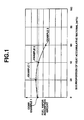
- Fig. 1 shows the relationship between the mix proportion of the heat accumulative material and the amount ("fuel vapor adsorption amount") of fuel vapor adsorbed by the gas storage canister, for the gas storage canisters A, B and C (respectively of Examples 1, 2 and 3) and the gas storage canister F (of Comparative Example 1). It is apparent from Fig. 1 that the gas storage canisters of respective Examples 1, 2 and 3 using the formed heat accumulative materials in certain amounts are improved in fuel vapor adsorption amount over the gas storage canister of Comparative Example 1 using only the activated carbon. It is also apparent from Fig.
- the gas storage canister of Example 1 including 20 % by weight of the formed heat accumulative material is the best in fuel vapor adsorption amount, while the gas storage canisters including 40 % by weight or more of the formed heat accumulative material are lowered in fuel vapor adsorption amount because the mix proportion of the activated carbon as the gas adsorbing material is less.
- Fig. 2 shows measured temperature rises of the gas adsorbing material during fuel vapor adsorption to the gas adsorbing material, for the gas storage canisters A, B and C (respectively of Examples 1, 2 and 3) and the gas storage canister F (Comparative Example 1). Specifically, Fig. 2 shows the relationship between the mix proportion of the heat accumulative material and the temperature of the gas adsorbing material. As apparent from Fig. 2, the temperature rise during fuel vapor adsorption can be effectively suppressed under the heat reservation effect of the formed heat accumulative material. However, in a region where the mix proportion of the heat accumulative material is 40 % by weight or more, the melting point of the phase change material is reached, so that a further temperature lowering cannot occur even though the mix proportion of the formed heat accumulative material increases.
- Fig. 3 shows the relationship between the time ("fuel vapor adsorbing time") for which fuel vapor is adsorbed by the gas storage canister ("testing canister”) and the breakthrough amount of fuel vapor, for the gas storage canisters A (Example 1) and F and G (respectively of Comparative Examples 1 and 2).
- the relationship was measured by a test conducted by using a test apparatus 1 as shown in Fig. 4.
- the test apparatus was arranged as follows: The inlet of each of the gas storage canisters A, F and G was connected to a fuel container 3. An air flow meter 2 was connected at its outlet to the fuel container 3. Additionally, a fuel leak detecting device 4 was connected to the outlet of the testing canister.
- Example 3 depicts that the gas storage canister A of Example 1 does not indicate fuel leak or breakthrough for a long time as compared with the gas storage canister of Comparative Example 1 using only the activated carbon, thereby exhibiting a good vapor adsorbing performance.
- the gas storage canister G of Comparative Example 2 in which the powdered heat accumulative agent is adhered to the outer surface of the activated carbon, fuel leak or breakthrough occurs for a short time as compared with the gas storage canister F of Comparative Example 1 using only the activated carbon. Consequently, it is not preferable that the powdered heat accumulative agent is adhered to the surface of the gas adsorbing material like the gas storage canister G of Comparative Example 2.
Landscapes
- Engineering & Computer Science (AREA)
- Chemical & Material Sciences (AREA)
- Combustion & Propulsion (AREA)
- Mechanical Engineering (AREA)
- General Engineering & Computer Science (AREA)
- Supplying Secondary Fuel Or The Like To Fuel, Air Or Fuel-Air Mixtures (AREA)
- Solid-Sorbent Or Filter-Aiding Compositions (AREA)
- Separation Of Gases By Adsorption (AREA)
Applications Claiming Priority (2)
| Application Number | Priority Date | Filing Date | Title |
|---|---|---|---|
| JP2004044253A JP2005233106A (ja) | 2004-02-20 | 2004-02-20 | キャニスタ |
| JP2004044253 | 2004-02-20 |
Publications (2)
| Publication Number | Publication Date |
|---|---|
| EP1566535A2 true EP1566535A2 (fr) | 2005-08-24 |
| EP1566535A3 EP1566535A3 (fr) | 2011-08-24 |
Family
ID=34709140
Family Applications (1)
| Application Number | Title | Priority Date | Filing Date |
|---|---|---|---|
| EP05003678A Withdrawn EP1566535A3 (fr) | 2004-02-20 | 2005-02-21 | Récipient de rétention des gaz |
Country Status (3)
| Country | Link |
|---|---|
| US (1) | US7309381B2 (fr) |
| EP (1) | EP1566535A3 (fr) |
| JP (1) | JP2005233106A (fr) |
Cited By (2)
| Publication number | Priority date | Publication date | Assignee | Title |
|---|---|---|---|---|
| EP1906001A3 (fr) * | 2006-09-13 | 2010-09-08 | MAHLE Filter Systems Japan Corporation | Réservoir |
| WO2023203117A1 (fr) * | 2022-04-21 | 2023-10-26 | Plastic Omnium Advanced Innovation And Research | Système de stockage de carburant de véhicule comprenant une vessie |
Families Citing this family (20)
| Publication number | Priority date | Publication date | Assignee | Title |
|---|---|---|---|---|
| WO2003106833A1 (fr) * | 2002-06-18 | 2003-12-24 | 大阪瓦斯株式会社 | Adsorbant de type a stockage de chaleur latente destine a une boite metallique et son procede de production |
| US7841321B2 (en) * | 2005-01-28 | 2010-11-30 | Aisan Kogyo Kabushiki Kaisha | Canister and method of manufacturing the same |
| US7228850B2 (en) * | 2005-08-12 | 2007-06-12 | Stant Manufacturing Inc. | Fuel vapor recovery canister |
| US7409946B2 (en) * | 2005-08-12 | 2008-08-12 | Stant Manufacturing Inc. | Fuel vapor recovery canister |
| US7472694B2 (en) * | 2005-11-08 | 2009-01-06 | Stant Manufacturing Inc. | Carbon canister with filter system |
| JP4708283B2 (ja) * | 2006-08-03 | 2011-06-22 | トヨタ自動車株式会社 | キャニスタ |
| JP2008303846A (ja) | 2007-06-11 | 2008-12-18 | Mahle Filter Systems Japan Corp | キャニスタ |
| US7600506B2 (en) * | 2008-03-12 | 2009-10-13 | ITB Group Ltd | Fuel tank having improved thermal stability |
| JP5148352B2 (ja) | 2008-04-25 | 2013-02-20 | 愛三工業株式会社 | キャニスタ |
| JP4795387B2 (ja) * | 2008-05-27 | 2011-10-19 | 愛三工業株式会社 | キャニスタとその製造方法 |
| JP5005613B2 (ja) | 2008-05-27 | 2012-08-22 | 愛三工業株式会社 | キャニスタ |
| JP5227084B2 (ja) * | 2008-05-27 | 2013-07-03 | 愛三工業株式会社 | 造粒蓄熱材とその製造方法 |
| JP4795386B2 (ja) * | 2008-05-27 | 2011-10-19 | 愛三工業株式会社 | キャニスタ |
| JP5242360B2 (ja) | 2008-12-11 | 2013-07-24 | 愛三工業株式会社 | 蒸発燃料処理装置 |
| JP5638298B2 (ja) | 2010-07-08 | 2014-12-10 | 愛三工業株式会社 | 造粒蓄熱材および蒸発燃料処理装置 |
| JP5744427B2 (ja) | 2010-07-13 | 2015-07-08 | 愛三工業株式会社 | 造粒蓄熱材および蒸発燃料処理装置 |
| CN103442785A (zh) * | 2011-04-08 | 2013-12-11 | 乔治洛德方法研究和开发液化空气有限公司 | 吸附剂与具有适应密度的相变材料的混合物 |
| US9365109B2 (en) | 2012-06-22 | 2016-06-14 | Bemis Manufacturing Company | Cap with adsorption media |
| KR102260453B1 (ko) * | 2014-04-03 | 2021-06-07 | 삼성디스플레이 주식회사 | 윈도우 부재 및 이를 구비하는 표시 장치 |
| JP6662077B2 (ja) * | 2016-02-15 | 2020-03-11 | 浜名湖電装株式会社 | 蒸発燃料処理装置 |
Citations (3)
| Publication number | Priority date | Publication date | Assignee | Title |
|---|---|---|---|---|
| JP2001145832A (ja) | 1999-11-19 | 2001-05-29 | Osaka Gas Co Ltd | 蓄熱機能付き吸着材およびその製造方法 |
| JP2001248504A (ja) | 1999-12-28 | 2001-09-14 | Tennex Corp | 蒸発燃料処理用のキャニスタ |
| JP2003311118A (ja) | 2002-02-08 | 2003-11-05 | Osaka Gas Co Ltd | 蓄熱機能付き吸着材およびその製造方法 |
Family Cites Families (6)
| Publication number | Priority date | Publication date | Assignee | Title |
|---|---|---|---|---|
| JPS6238468U (fr) * | 1985-08-26 | 1987-03-07 | ||
| JPH0610781A (ja) * | 1992-06-22 | 1994-01-18 | Toyoda Gosei Co Ltd | 燃料吸収体及びその製造方法 |
| JP3337398B2 (ja) * | 1997-06-04 | 2002-10-21 | 株式会社 マーレ テネックス | 蒸発燃料の処理装置用吸着剤及びその製造方法 |
| JP3540286B2 (ja) * | 2001-04-13 | 2004-07-07 | 株式会社デンソー | 燃料蒸気処理装置 |
| WO2003106833A1 (fr) * | 2002-06-18 | 2003-12-24 | 大阪瓦斯株式会社 | Adsorbant de type a stockage de chaleur latente destine a une boite metallique et son procede de production |
| DE10329200A1 (de) * | 2003-06-28 | 2005-02-03 | Mahle Filtersysteme Gmbh | Adsorptionsfilter für Kraftstoffdämpfe |
-
2004
- 2004-02-20 JP JP2004044253A patent/JP2005233106A/ja active Pending
-
2005
- 2005-02-18 US US11/060,585 patent/US7309381B2/en not_active Expired - Lifetime
- 2005-02-21 EP EP05003678A patent/EP1566535A3/fr not_active Withdrawn
Patent Citations (3)
| Publication number | Priority date | Publication date | Assignee | Title |
|---|---|---|---|---|
| JP2001145832A (ja) | 1999-11-19 | 2001-05-29 | Osaka Gas Co Ltd | 蓄熱機能付き吸着材およびその製造方法 |
| JP2001248504A (ja) | 1999-12-28 | 2001-09-14 | Tennex Corp | 蒸発燃料処理用のキャニスタ |
| JP2003311118A (ja) | 2002-02-08 | 2003-11-05 | Osaka Gas Co Ltd | 蓄熱機能付き吸着材およびその製造方法 |
Cited By (4)
| Publication number | Priority date | Publication date | Assignee | Title |
|---|---|---|---|---|
| EP1906001A3 (fr) * | 2006-09-13 | 2010-09-08 | MAHLE Filter Systems Japan Corporation | Réservoir |
| WO2023203117A1 (fr) * | 2022-04-21 | 2023-10-26 | Plastic Omnium Advanced Innovation And Research | Système de stockage de carburant de véhicule comprenant une vessie |
| BE1030475B1 (fr) * | 2022-04-21 | 2023-11-27 | Plastic Omnium Advanced Innovation & Res | Système de stockage de carburant de véhicule comprenant une vessie |
| CN119053468A (zh) * | 2022-04-21 | 2024-11-29 | 全耐塑料高级创新研究公司 | 包括囊的车辆燃料存储系统 |
Also Published As
| Publication number | Publication date |
|---|---|
| US7309381B2 (en) | 2007-12-18 |
| EP1566535A3 (fr) | 2011-08-24 |
| JP2005233106A (ja) | 2005-09-02 |
| US20050188851A1 (en) | 2005-09-01 |
Similar Documents
| Publication | Publication Date | Title |
|---|---|---|
| US7309381B2 (en) | Gas storage canister | |
| EP1582731B1 (fr) | Récipient de rétention de vapeur de carburant | |
| US7543574B2 (en) | Canister | |
| JP4508867B2 (ja) | キャニスター用潜熱蓄熱型吸着材及びその製造方法 | |
| CN101802127B (zh) | 蓄热材料的制造方法、蓄热材料、带蓄热功能的吸附材料、容器 | |
| JP5005613B2 (ja) | キャニスタ | |
| JP2010142679A (ja) | 蓄熱材が付与された複合吸着材とその製造方法 | |
| JP4526333B2 (ja) | キャニスター用吸着材、その製造方法及び燃料蒸散防止用キャニスター | |
| JP4956232B2 (ja) | 蓄熱機能付吸着材の製造方法及び蓄熱機能付吸着材並びにキャニスター | |
| JP4471700B2 (ja) | キャニスタ | |
| JP4707683B2 (ja) | 蓄熱機能付吸着材の製造方法及び蓄熱機能付吸着材並びにキャニスター | |
| JP2005282481A (ja) | キャニスタ | |
| JP5462765B2 (ja) | 蓄熱機能付吸着材の製造方法及び蓄熱機能付吸着材並びにキャニスター | |
| JP2023069542A (ja) | キャニスタ | |
| JP5250060B2 (ja) | 蓄熱機能付吸着材の製造方法及び蓄熱機能付吸着材並びにキャニスター | |
| JP4861136B2 (ja) | 蓄熱機能付吸着材の製造方法及び蓄熱機能付吸着材並びにキャニスター | |
| KR100745261B1 (ko) | 캐니스터용 잠열 축열형 흡착재 및 그의 제조 방법 | |
| WO2023080208A1 (fr) | Réservoir à charbon actif et véhicule automobile équipé de celui-ci | |
| JP2019049215A (ja) | キャニスタ |
Legal Events
| Date | Code | Title | Description |
|---|---|---|---|
| PUAI | Public reference made under article 153(3) epc to a published international application that has entered the european phase |
Free format text: ORIGINAL CODE: 0009012 |
|
| AK | Designated contracting states |
Kind code of ref document: A2 Designated state(s): AT BE BG CH CY CZ DE DK EE ES FI FR GB GR HU IE IS IT LI LT LU MC NL PL PT RO SE SI SK TR |
|
| AX | Request for extension of the european patent |
Extension state: AL BA HR LV MK YU |
|
| RAP1 | Party data changed (applicant data changed or rights of an application transferred) |
Owner name: OSAKA GAS CO., LTD. Owner name: MAHLE FILTER SYSTEMS JAPAN CORPORATION |
|
| PUAL | Search report despatched |
Free format text: ORIGINAL CODE: 0009013 |
|
| AK | Designated contracting states |
Kind code of ref document: A3 Designated state(s): AT BE BG CH CY CZ DE DK EE ES FI FR GB GR HU IE IS IT LI LT LU MC NL PL PT RO SE SI SK TR |
|
| AX | Request for extension of the european patent |
Extension state: AL BA HR LV MK YU |
|
| RIC1 | Information provided on ipc code assigned before grant |
Ipc: F02M 25/08 20060101AFI20110715BHEP |
|
| AKY | No designation fees paid | ||
| REG | Reference to a national code |
Ref country code: DE Ref legal event code: R108 Effective date: 20120502 |
|
| STAA | Information on the status of an ep patent application or granted ep patent |
Free format text: STATUS: THE APPLICATION IS DEEMED TO BE WITHDRAWN |
|
| 18D | Application deemed to be withdrawn |
Effective date: 20120225 |