EP1564946B1 - Kanalschätzung bei Mehrträgerübertragung - Google Patents
Kanalschätzung bei Mehrträgerübertragung Download PDFInfo
- Publication number
- EP1564946B1 EP1564946B1 EP05002693A EP05002693A EP1564946B1 EP 1564946 B1 EP1564946 B1 EP 1564946B1 EP 05002693 A EP05002693 A EP 05002693A EP 05002693 A EP05002693 A EP 05002693A EP 1564946 B1 EP1564946 B1 EP 1564946B1
- Authority
- EP
- European Patent Office
- Prior art keywords
- dimensional
- data
- domain
- carrier
- transfer characteristic
- Prior art date
- Legal status (The legal status is an assumption and is not a legal conclusion. Google has not performed a legal analysis and makes no representation as to the accuracy of the status listed.)
- Expired - Fee Related
Links
- 230000005540 biological transmission Effects 0.000 title claims description 28
- 238000012546 transfer Methods 0.000 claims description 120
- 238000000034 method Methods 0.000 claims description 42
- 239000000969 carrier Substances 0.000 claims description 21
- 239000000284 extract Substances 0.000 claims description 8
- 238000005259 measurement Methods 0.000 claims description 7
- 230000003247 decreasing effect Effects 0.000 claims 1
- 238000001228 spectrum Methods 0.000 description 20
- 238000009826 distribution Methods 0.000 description 17
- 238000001914 filtration Methods 0.000 description 11
- 238000012545 processing Methods 0.000 description 6
- 238000004364 calculation method Methods 0.000 description 5
- 239000000470 constituent Substances 0.000 description 5
- 238000010586 diagram Methods 0.000 description 5
- 238000013213 extrapolation Methods 0.000 description 5
- 239000012141 concentrate Substances 0.000 description 3
- 239000013256 coordination polymer Substances 0.000 description 3
- 238000012937 correction Methods 0.000 description 3
- 230000007850 degeneration Effects 0.000 description 2
- 239000006185 dispersion Substances 0.000 description 2
- 102100035971 Molybdopterin molybdenumtransferase Human genes 0.000 description 1
- 101710119577 Molybdopterin molybdenumtransferase Proteins 0.000 description 1
- 230000006978 adaptation Effects 0.000 description 1
- 230000000052 comparative effect Effects 0.000 description 1
- 230000000694 effects Effects 0.000 description 1
- 230000005684 electric field Effects 0.000 description 1
- 238000000605 extraction Methods 0.000 description 1
- 230000010354 integration Effects 0.000 description 1
- 238000013507 mapping Methods 0.000 description 1
- 239000011159 matrix material Substances 0.000 description 1
- 238000005457 optimization Methods 0.000 description 1
- 238000004088 simulation Methods 0.000 description 1
- 238000005303 weighing Methods 0.000 description 1
Images


Classifications
-
- H—ELECTRICITY
- H04—ELECTRIC COMMUNICATION TECHNIQUE
- H04L—TRANSMISSION OF DIGITAL INFORMATION, e.g. TELEGRAPHIC COMMUNICATION
- H04L25/00—Baseband systems
- H04L25/02—Details ; arrangements for supplying electrical power along data transmission lines
- H04L25/0202—Channel estimation
- H04L25/0224—Channel estimation using sounding signals
- H04L25/0228—Channel estimation using sounding signals with direct estimation from sounding signals
- H04L25/023—Channel estimation using sounding signals with direct estimation from sounding signals with extension to other symbols
- H04L25/0232—Channel estimation using sounding signals with direct estimation from sounding signals with extension to other symbols by interpolation between sounding signals
-
- H—ELECTRICITY
- H04—ELECTRIC COMMUNICATION TECHNIQUE
- H04L—TRANSMISSION OF DIGITAL INFORMATION, e.g. TELEGRAPHIC COMMUNICATION
- H04L27/00—Modulated-carrier systems
- H04L27/26—Systems using multi-frequency codes
- H04L27/2601—Multicarrier modulation systems
- H04L27/2647—Arrangements specific to the receiver only
-
- H—ELECTRICITY
- H04—ELECTRIC COMMUNICATION TECHNIQUE
- H04L—TRANSMISSION OF DIGITAL INFORMATION, e.g. TELEGRAPHIC COMMUNICATION
- H04L5/00—Arrangements affording multiple use of the transmission path
- H04L5/003—Arrangements for allocating sub-channels of the transmission path
- H04L5/0048—Allocation of pilot signals, i.e. of signals known to the receiver
Definitions
- This invention relates to an apparatus and method for receiving terrestrial digital broadcast signals, according to the preamble of the independent claims.
- the preamble of the independent claims is known from US-B 1-6 654 429 .
- Relevant receiving apparatus and method are also known from YE LI: "Pilot-symbol-aided channel estimation for OFDM in wireless systems" 49TH VEHICULAR TECHNOLOGY CONFERENCE, PISCATAWAY, NJ, USA, IEEE, vol. 2, 16 May 1999, pages 1131-1135 , ISBN: 0-7803-5565-2 and from US 2003/016645 A1 .
- the OFDM (Orthogonal Frequency Division Multiplex) scheme is widely known as a modulation scheme for terrestrial digital broadcasts. This scheme is widely employed for terrestrial digital broadcast systems, e.g. European DVB-T (Digital Video Broadcasting-Terrestrial) standard and Japanese ISDB-T (Integrated Services Digital Broadcasting-Terrestrial) standard.
- European DVB-T Digital Video Broadcasting-Terrestrial
- Japanese ISDB-T Integrated Services Digital Broadcasting-Terrestrial
- the OFDM scheme adopts so-called a multi-carrier scheme using a multiplicity of carriers allotted equally spaced on the frequency axis, i.e. modulation scheme for sequentially forwarding at an interval of unit transmission time (hereinafter, referred to as a "symbol transmission period") an OFDM symbol (hereinafter, referred to as a "symbol”) obtained by modulating such carriers based on transmission data.
- the OFDM scheme has a feature resistive to multipath disturbance because of its capability of setting a symbol transmission period longer as compared to the single-carrier-based modulation scheme such as QAM and VSB.
- a pilot carrier signal is used for facilitating a deduction of an on-transmission-line transfer characteristic, together with a data carrier signal serving to convey video and audio information data.
- a pilot carrier signal is defined and called scattered pilot carrier signal (hereinafter, referred to as "SP signal").
- SP signal scattered pilot carrier signal
- the other carrier than SP signals included in the OFDM symbol space, is a data carrier signal modulated with QAM, PSK or the like.
- Patent Document 1 Japanese Patent Kokai No. 11-163822
- Patent Document 2 Japanese Patent Kokai No. 11-239115
- Patent Document 3 Japanese Patent Kokai No. 2002-261729
- Patent Document 4 Japanese Patent Kokai No. 2003-101503
- This prior art is of a scheme that a two-dimensional filtering process is made on the transfer characteristic of SP carriers allotted disperse within the OFDM symbol space, thereby estimating the transfer characteristic of other data carriers.
- the two-dimensional filtering process is realized by a combination of a one-dimensional filter in a direction of symbol time (hereinafter, referred to as “symbol filter”) and a one-dimensional filter in a direction of carrier frequency (hereinafter, referred to as “carrier filter”).
- symbol filter a one-dimensional filter in a direction of symbol time
- carrier filter a one-dimensional filter in a direction of carrier frequency
- the symbol filter uses an IIR (infinite impulse response) filter because of restriction in operation amount.
- IIR infinite impulse response
- the IIR filter does not have a phase linearity and hence cannot determine its absolute delay amount unambiguously.
- the problem the present invention solves includes, as one example, to provide a signal receiving apparatus and method which is high in estimation accuracy of transfer characteristic and less in error rate during signal decoding.
- a signal receiving apparatus according to one aspect of the present invention is described in claim 1.
- a signal receiving method according to another aspect of the present invention is described in claim 7.
- the OFDM symbol is constituted of 13 segments, as shown in Fig. 1 .
- Each segment, in transmission mode 1, contains 108 waves of carriers, for example.
- the partial receiver refers to a receiver for demodulating only the carriers included in segment 0 positioned centrally of the 13 segments.
- Fig. 2 shows the values of modulation parameters in transmission mode 1 while in Fig. 3 is shows the values of constant parameters to be used in the explanations.
- Fig. 4 a configuration of a receiver 1 based on a first example.
- the receiver 1 is configured mainly by a symbol detecting section 11, a symbol storing section 12, a transfer-characteristic estimating section 20 and a data decoding section 30.
- the arrow representing a signal flow in the figure shows the major flow of signal between the constituent elements.
- the response and monitor signals associated with the major signal assumably includes the case of transfer in the direction opposite to the arrow of the figure.
- the arrow in the figure is to conceptionally represent a signal flow between the constituent elements.
- each signal must not be faithfully transmitted/received as per the route shown by the arrow.
- the constituent elements must not be divided faithfully as shown in the figure.
- the symbol detecting section 11 detects carriers contained in each of the symbols sequentially transmitted, and determines a complex amplitude S p,k of the carrier (hereinafter, referred to as "carrier amplitude").
- S p,k represents a p-th carrier amplitude in a k-th symbol.
- the symbol detecting section 11 is configured by the constituent circuits of a tuner, an A/D converter, a guard-interval removing circuit, an FET circuit and so on. However, the configuration is not limited to that example.
- the symbol storing section 12 is a circuit which selects those central of the channel in the number of nX out of the carrier amplitudes outputted from the symbol detecting section 11 and stores those for a time of nY symbols in a direction of symbol time. Namely, concerning the carrier groups (in the number of nX ⁇ nY) within an OFDM symbol space shown in Fig. 6 , carrier amplitudes S p,q ( -nX/2 ⁇ p ⁇ nX/2, k - nY ⁇ q ⁇ k) are stored. In the below, explanation is on the assumption that the stored carrier amplitudes are in a two-dimensional matrix ⁇ S p,q : (p, q) ⁇ Z 2D ⁇ on a space (p, q).
- Z 2D corresponds a two-dimensional fast Fourier transform domain (hereinafter, referred to as "2D-FFT domain”) in the figure.
- the domain has a range defined, in the direction of carrier frequency, as - nX / 2 ⁇ p ⁇ nX / 2 and, in the direction of symbol time, as k - nY ⁇ q ⁇ k .
- Fig. 7 is shown a relationship between each piece of carrier amplitude information arranged two-dimensionally on the space (p, q) as an OFDM symbol space and an attribute of each carrier (attribute that the relevant carrier is an SP signal or a data carrier signal).
- SP signals are superimposed at a rate of one out of 12 carriers wherein the superimposing position shifts cyclically by 3 carriers per symbol.
- the data decode section 30 is a section which extracts carrier amplitudes ⁇ S p,q : (p, q) ⁇ Z EST ⁇ of within an estimating domain Z EST (-wX/2 ⁇ p ⁇ wX/2, k-nY/2-wY/2 ⁇ q ⁇ k-nY/2+wY/2) shown in Fig. 6 from the carrier amplitude data groups stored in the symbol storing section 12 thereby making a decode processing thereon.
- the transfer-characteristic estimating section 20 is a section which calculates an deduced transfer characteristic on the charier amplitude of within the estimating domain Z EST depending upon the carrier amplitude stored in the symbol storing section 12 and supplies it to the data decode section 30.
- the data decode section 30 makes such processing as equalization, de-interleave and Reed-Solomon decode depending upon a carrier amplitude of from the symbol storing section 12 and an deduced transfer characteristic of from the transfer-characteristic estimating section 20, and outputs the reception data obtained as a result thereof.
- the transfer-characteristic estimating section 20 makes a deduction of transfer characteristic over the symbol sections successive in the number of wY, it may operate at a rate once per receiving wY symbols without the need to operate in timing of every reception of a symbol. Such operation timing is true for the operation timing in the data decode section 30.
- Fig. 8 a configuration of the transfer-characteristic estimating section 20.
- the transfer-characteristic estimating section 20 is configured mainly with an SP-signal transfer characteristic calculating circuit 21, a two-dimensional Fourier transform circuit 22, a two-dimensional filter circuit 23, a two-dimensional inverse Fourier transform circuit 24 and an deduced-transfer-characteristic output circuit 25.
- these circuits are respectively referred to as a calculating circuit 21, a transform circuit 22, a filter circuit 23, an inverse transform circuit 24 and an output circuit 25.
- the transfer-characteristic estimating section 20 As noted before, the terrestrial digital broadcast under the ISDB-T standard is previously defined with an existence point of SP signals in a carrier arrangement on the OFDM symbol space and a complex amplitude value of SP signals during transmission. Accordingly, the calculation circuit 21 extracts only a carrier amplitude concerning the SP signal from the carrier amplitudes supplied from the symbol storing section 12 and divides it by a known value of transmission complex amplitude. This can determine a transfer characteristic ⁇ H p,q : (p, q) ⁇ Z 2D ⁇ in connection with the SP signals spotted on the space (p, q). In this connection, calculation procedure is as follows.
- R p,q is a sending complex amplitude value of the known SP signal.
- the calculating circuit 21 after determining transfer characteristics H p,q on all the elements (p, q) within the domain Z 2D , outputs a result thereof to the transform section 22.
- the transform section 22 carries out a two-dimensional Fourier transform on the SP-signal transfer characteristic ⁇ H p,q ⁇ on the space (p, q) into an SP-signal transfer characteristic ⁇ h m,n : (m, n) ⁇ Z TRA ⁇ on the space (m, n).
- a carrier frequency direction (p direction) of the space (p, q) the frequency domain is transformed into a time domain by carrying out an IFFT (inverse fast Fourier transform).
- IFFT inverse fast Fourier transform
- q direction the time domain is transformed into a frequency domain by carrying out a FFT (fast Fourier transform).
- the direction of m-axis corresponds to time dimension and the direction of n-axis to frequency dimension, respectively.
- the domain Z 2D on the space (p, q) corresponds to the domain Z TRA transformed onto the space (m, n). This domain is defined in the m-axis direction as - nX / 2 ⁇ m ⁇ nX / 2 and in the n-axis direction as - nY / 2 ⁇ n ⁇ nY / 2.
- the filter circuit 23 is a circuit for making a predetermined filtering processing on the data group Fourier-transformed onto the space (m, n) by the transform circuit 22.
- on-transmission-line transfer characteristic has a power spectrum distribution that tends to concentrate onto a particular domain of the space (m, n), depending upon a nature of transmission line.
- the filter circuit 23 multiplies a real coefficient of two-dimensional filter window ⁇ W m,n ⁇ having a pass band covering that domain on the SP-signal transfer characteristic ⁇ h m,n ⁇ of the space (m, n), thereby calculating an deduced transfer characteristic ⁇ g m,n ⁇ on the space (m, n).
- the inverse transform circuit 24 carries out a two-dimensional inverse Fourier transform, as an inverse process to two-dimensional Fourier transform, on the deduced transfer characteristic ⁇ g m,n ⁇ supplied from the filter circuit 23 to thereby calculate an deduced transfer characteristic ⁇ G p,q : (p, q) ⁇ Z 2D ⁇ of the space (p, q).
- the deduced transfer characteristic ⁇ G p,q ⁇ calculated by the inverse transform circuit 24 is supplied to the output circuit 25.
- the same circuit extracts the deduced transfer characteristic ⁇ G p,q : (p, q) ⁇ Z EST ⁇ corresponding to the carrier amplitude of deduced domain Z EST extracted by the data decode section 30 and supplies the extracted data to the data decode section 30.
- nX and nY may use, as concrete values, further greater values than the values of this example.
- a signal receiver includes: a signal detecting section 11 for receiving an OFDM signal superimposed with a pilot signal having a particular known complex amplitude over a predetermined carrier of within a transmission symbol on a transmission unit basis of a transmission symbol generated by orthogonally modulating a plurality of carriers on a basis of transmission data, and allotting a reception signal obtained by detecting a carrier group included in a plurality of successive ones of the transmission symbols in a two-dimensional data domain on a two-dimensional space corresponding to carrier frequency and symbol time; a transfer characteristic estimating section 20 for estimating a reception signal transfer characteristic relative to each of the reception signals depending upon the pilot signal allotted in the two-dimensional data domain; and a data decode section 30 for decoding the transmission data depending upon the reception signal and the reception signal transfer characteristic; wherein the transfer characteristic estimating section 20 includes: a calculator circuit 21 for calculating a pilot signal transfer characteristic for the pilot signal allotted in the two-dimensional data domain; a transformer circuit 22 for
- the two-dimensional filtering process conventionally realized by convolution integration in a space (p, q) is to be realized by multiplication of a window in space (m, n) after two-dimensional Fourier transform.
- the two-dimensional filter window coefficient W m,n is a real number. Accordingly, it is possible to correctly calculate a deduced transfer characteristic for a particular carrier amplitude.
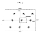
- the m-axis corresponds to time and the n-axis to frequency respectively, as mentioned before. If expressing it more correctly, the m-axis corresponds to a delay time of impulse response over the transmission line while the n-axis corresponds to a variation frequency (Doppler frequency) over the transmission line. Therefore, the power spectrum of on-transmission-line transfer characteristic appearing on the space (m, n) exhibits a tendency to concentrate to a particular domain on the space (m, n) in accordance with a reception environment, as mentioned before.
- Fig. 9 shows a power spectrum distribution
- power spectrum distribution density is expressed by simulation in the hatched domains at black dots and therearound.
- the power spectrum distribution of transmission line transfer characteristic is to concentrate in a domain A nearby the origin of the space (m, n).
- the first requirement for the two-dimensional filter window explained in the first example, is to pass such a power spectrum of on-transmission-line transfer characteristic.
- a plurality of power spectrum distributions spotted outside the domain A in Fig. 9 are aliasing components of a power spectrum of on-transmission-line transfer characteristic in nature.
- the SP-signal transfer characteristic ⁇ H p,q ⁇ as an output of the calculating circuit 21 is a sub-sampled reception signal transfer characteristics at a superimposition point of the SP signal with a result that an aliasing component occurs on the space (m, n).
- the second requirement for the two-dimensional filter window lies to remove these aliasing components.
- the third requirement for the two-dimensional filter window includes a function to suppress the noise component contained in the reception signal.
- the two-dimensional filter window desirably is provided in a suitable position on the space (m ,n) and has a required minimum size to pass only the power spectrum of on-transmission-line transfer characteristic. Accordingly, provided that the receiver is used only in the environment of reception environment 1 shown in Fig, 9 , the two-dimensional filter window is satisfactorily set with a pass band only in a quite narrow domain nearby the origin of the space (m, n).
- the power spectrum distribution of on-transmission-line transfer characteristic on the space (m, n) greatly changes depending upon reception environment.
- the urban area crowded with edifices such as high-rise buildings there is an increase of multipath delay due to reflection wave whose power spectrum distribution is given a distribution spread in the m-axis direction, as shown in Fig. 10 .
- the reception environment where the receiver is mounted and used on a mobile body as a vehicle there is an increase of in-time variation of on-transmission-line characteristic whose power spectrum distribution is given a distribution spread in the n-axis direction, as shown in Fig. 11 .
- the actual receiver is necessarily set previously with a broad pass band on the two-dimensional filter window.
- a pass band of two-dimensional filter window is set in a domain B shown in Fig. 12 , it can cope with a transmission line having a power spectrum distribution of from 0 to Te/4 (Te: effective symbol period) on multipath delay time and from - Fa/8 to Fa/8 (Fa: symbol transmission frequency) on Doppler frequency.
- the receiver 1 of this example is similar in configuration to the block diagram of the first example shown in Fig. 4 except for the internal configuration of its transfer-characteristic estimating section 20a.
- Fig. 13 is shown a configuration of a transfer-characteristic estimating section 20a of this example.
- the transfer-characteristic estimating section 20a is configured mainly with an SP-signal transfer characteristic calculating circuit 21, a two-dimensional Fourier transfer circuit 22, a two-dimensional filter circuit 23, a two-dimensional inverse Fourier transfer circuit 24, an deduced transfer characteristic output circuit 25 and a filter-constant setting circuit 26 (hereinafter, referred to as a "setting circuit 26").
- the calculating circuit 21 and the output circuit 25 are similar to the first example and hence omitted of their explanations, thus using the similar abbreviations to the first example.
- the filter circuit 23 has a pass band of two-dimensional filter window to be determined by the parameters of window frame pointer (m 0 , n 0 ) and window width (m w , n w ) notified from the setting circuit 26.
- the pass band C of two-dimensional filter window of this example is set with widths m w and n w respectively in m-axis and n-axis directions with reference to a window frame pointer (m 0 , n 0 ) as a basis point, as shown in Fig. 14 .
- the user using the receiver may adjust the parameters of the setting circuit 26 by manual operation depending upon a reception condition.
- the configuration may be provided such that the setting circuit 26 acquires information representative of reception condition such as reception electric field intensity and reception signal error rate so that a suitable pass band can be set corresponding to the information according to a predetermined ROM table or the like.
- the setting parameters in this example are not limited to the above case, e.g. designation may be made for three or more window frame pointer defining a pass band through the two-dimensional filter window. Otherwise, the configuration may be to set a desired pass band by use of a plurality of window frame pointers and a plurality of pieces of window frame information.
- this example further includes, in addition to the configuration of the first example, a setting circuit 26 for supplying the filter circuit 23 with a setting parameter defining a setting position of two-dimensional filter window on the basis of an input instruction.
- the filter circuit 23 is allowed to define a pass band thereof depending upon the setting parameter.
- the present example can freely set a pass band of two-dimensional filter window corresponding to various reception environment, an deduced transfer characteristic can be accurately calculated without picking up unnecessary noise components through the pass band.
- the receiver in the case that the similar function to the present example is realized by the conventional convolution operation in the space (p, q), the receiver necessarily stores a set of many convolution coefficients in accordance with window frame pointer (m 0 , n 0 ) and window width (m w , n w ) or recalculates such a set of convolution coefficients each time the window position or window width is changed.
- window frame pointer m 0 , n 0
- window width m w , n w
- This embodiment is configured to make a predetermined selection process on a data group existing within a pass band of two-dimensional filter window thereby further narrowing the data-capturing pass band.
- the receiver of this embodiment is similar in configuration to that of the first example. The difference lies only in that the following processing is added upon the filtering process in the filter circuit 23. Furthermore, this embodiment may be used together in the second example.
- the two-dimensional filter circuit 23 of this embodiment is assumably set with a pass band A in the two-dimensional filter window, as shown in the foregoing Fig. 9 for example.
- the actual pass band of the two-dimensional filter window is degenerated to the range of a domain D shown in Fig. 15 in the case of an ideal reception environment shown in Fig. 9 for example.
- This makes it possible to remove, out of the pass band, the noise component existing within the range of the pass band A previously set to the two-dimensional filter window, thus enabling to improve the accuracy of transfer-characteristic estimating operation.
- Fig. 16 is shown a manner of pass band degeneration of the two-dimensional filter window in the case this embodiment is applied in the reception environment of Fig. 10 .
- the data within the range of the domain D and E naturally falls under the case of P m , n > Pth .
- the present embodiment is not limited to that case.
- the determination value may use a complex absolute value
- the above process is implemented by dividing the pass band of two-dimensional filter window into a plurality of segments, for example. Namely, power is calculated on the data included in each of the segments and a mean power is calculated on each segment so that the mean power is compared with a predetermined threshold to thereby set the relevant segment as in a pass band or as outside of the pass band. This can suppress the influence of a local power variation caused in the two-dimensional filter window. Meanwhile, because the determination process with a threshold is on a small-segment basis, it is possible to reduce the number of operations required in the determination process with a threshold and hence to simplify the process.
- the SP-carrier transfer characteristic ⁇ H p,q (p, q) ⁇ Z 2D ⁇ , in nature, is limitlessly spread in both directions of frequency (p-axis direction) and time (q-axis direction) with in a space (p, q), it is an extract of only a Z 2D domain as a part thereof, as shown in Fig. 7 for example. Accordingly, in the ⁇ h m,n ⁇ obtained by making a two-dimensional Fourier transform on the domain Z 2D , an actually not existent image component is included by the influence of a domain end.
- ⁇ h m,n ⁇ may be determined by making a two-dimensional Fourier transform after previously multiplying, on ⁇ H p,q ⁇ , a window coefficient ⁇ W p,q ⁇ of a 2D-FFT domain.
- the multiplication with the window coefficient in this case may be naturally made on an SP-carrier location.
- the filter circuit 23 of the receiver of this embodiment is characterized to selectively acquire only the data having a power equal to or greater than a reference value out of a data group included in the two-dimensional filter window.
- the present embodiment can freely degenerate the pass band of the two-dimensional filter window depending upon a power level of the data existing within the filter extracting domain. This can exclude the noise component having a low power level and extract only a spectrum component of an SP signal having a high power level, thus making it possible to accurately calculate an deduced transfer characteristic.
- the present embodiment made in order to solve such a problem, is characterized to calculate a mean noise power over a domain where no on-transmission-line transfer components exist on the space (m, n) and to determine a window component W m,n of two-dimensional filter window depending upon such a calculated value.
- the receiver of this embodiment is similar in configuration to the first example except for a difference in the operation process of a window coefficient W m,n by the two-dimensional filter circuit 23.
- a noise observing domain F is provided at a predetermined position of the space (m, n) to thereby calculate a mean noise power NP of within the relevant domain.
- the mean noise power NP measured at the noise observing domain F is first utilized as a threshold for the foregoing embodiment, and further a value of window coefficient W m, n is determined by a least square criterion.
- the window coefficient W m,n is set of a value in a manner maximizing the power ratio of a transfer characteristic component of the SP signal as an output of the filter circuit 23 and a noise component. This makes it possible to narrow the pass band of the two-dimensional filter window domain A down to a further optimal domain E, as shown in Fig. 18 .
- the extracting domain A of two-dimensional filter window may be further divided into smaller segments so that the above process can be carried out on each segment, similarly to the case of the foregoing embodiment.
- a value of Q m , n P m , n - NP P m , n may be once determined by use of that and the mean noise power NP, so that determination with a threshold is made on such Q m,n thereby setting 1 or 0 of window coefficient W m,n .
- the receiver of this embodiment is characterized in that the filtering circuit 23 takes, as a reference value, a noise power measurement value of the other domain than the two-dimensional filter window and selectively acquires only the data having a power equal to or greater than the reference value, wherein the window function on the filter extracting domain is made to a reference in accordance with the noise power measurement value.
- This embodiment is characterized in that carrier-based reliability information is generated by use of the mean noise power NP calculated in the foregoing embodiment so that the Viterbi decoder provided in the data decode section carries out a decode processing of reception data depending upon such reliability information.
- Fig. 19 is shown a configuration of a receiver 1a and data decode section 30a according to the present embodiment.
- the configuration of a signal detecting section 10 and transfer-characteristic estimating section 20 is assumably similar to the foregoing embodiment.
- a carrier extracting circuit 31a has a function similar to the counterpart circuit included in the foregoing data decode section 30, to extract a carrier amplitude ⁇ S p,q : (p, q) ⁇ Z EST ⁇ of within the deduction domain Z EST shown in the foregoing Fig. 6 from among the carrier amplitude data group stored in a symbol storing circuit 15 of the signal detecting section 10 and supplies it to the next-staged equalizer circuit 32a.
- the equalizer circuit 32a divides the carrier amplitude by an deduced transfer characteristic supplied from the transfer-characteristic estimating section 20 to thereby equalize the amplitude and supplies a equalized carrier amplitude to the next-staged bit-metric calculating circuit 33a.
- the bit-metric calculating circuit 33a is a circuit for calculating a bit metric for use in Viterbi decode.
- bit-metric calculating techniques are roughly divided as those using hard decisions and those using soft decisions.
- hard decision is a method to decide only a single-valued demodulation output on each reception symbol.
- soft decision is a method to output a deduction value of reception symbol value and its reliability both as demodulation values. Usually, this is to be realized by quantizing a reception signal into levels more than its symbol value.
- there are further various schemes in the decision method using soft decision In any case, it is a general practice to calculate a bit metric in an amount of bits per the carrier from one carrier amplitude according to a predetermined constellation mapping. Namely, from one carrier of after equalization, two bit metrics as bits in an amount of one symbol is calculated for QPSK while four bit metrics as bits in an amount of one symbol is calculated for 16 QAM.
- a reliability-information calculating circuit 36a is a circuit for calculating carrier-based reliability information depending upon an deduced transfer characteristic H p,q and noise mean power NP supplied from the transfer-characteristic estimating section 20.
- the reliability information of each carrier is B p,q
- the above equation is on the case using carrier-based deduced CN value as reliability information.
- a bit-metric weighting circuit 34a is a circuit which multiplies the bit metric supplied from the bit-metric calculating circuit 33a by the reliability information supplied from the reliability-information calculating circuit 36a thereby making a predetermined weighing.
- An error correcting circuit 35a is a circuit which makes a Viterbi decode on the reception signal depending upon a bit metric done by a predetermined weighting supplied from the bit-metric weighting circuit 34a and carries out various error corrections, such as predetermined defined hierarchical division, deinterleave process, derandamization process and RS decode process, and a decode process.
- the data decode section 30 thereof includes the reliability-information calculating circuit 36a for calculating reliability information on each of reception carriers depending upon an deduced transfer characteristic and noise power measurement value supplied from the transfer-characteristic estimating section 20, and the bit-metric weighting circuit 34a for making a weighting on a restoration parameter of upon reception data restoration depending upon the reliability information.
- the receiver according to the present embodiment can make a Viterbi decoding by use of a properly weighted bit metric depending upon a carrier-based amplitude and an on-transmission-line noise power, thus enabling to improve the error-rate correction characteristic on the reception signal.
- the present example has been made in order to relieve the influence of such adjacent domains.
- the operation process in the SP transfer-characteristic calculation circuit 21 is improved in order to calculate an SP-signal transfer characteristic by an extrapolation process.
- the receiver based on this example assumably has a configuration similar to the first example.
- transfer characteristics ⁇ H p,q ⁇ at the SP signal points are calculated for the domain of the segment where SP signals are superimposed (central segment), similarly to the conventional.
- (X) * means a conjugate complex to a complex (X).
- FIG. 20A represents a left end part of the central segment and a left side adjoining domain to the central segment, wherein the area where no carrier signals exist on the p-axis corresponds to the left domain.
- Fig. 20B shows a procedure to deduce the SP-signal transfer characteristics assumed within the left domain by the extrapolation shown in the above equation.
- the virtual SP-signal transfer characteristics within the left domain are deduced from the SP-signal transfer characteristic lying in a mirror-image relationship on the p-axis about, as a symmetric point, a position of the SP-signal transfer characteristic H B,q at the extreme left end of the central segment.
- Fig. 20 there is also shown together an amplitude characteristic (20C) and phase characteristic (20D) of SP-signal transfer characteristic to be deduced by the above procedure.
- the amplitude characteristic and phase characteristic of SP-signal transfer characteristic in the adjacent domain is a smooth amplitude/phase characteristic continuous with the central segment. Namely, the present example can relieve the influence upon deduced transfer characteristic as caused by putting 0 the transfer characteristic in the adjacent domain.
- a continual pilot signal hereinafter, referred to as a "CP signal”
- CP signal continual pilot signal
- the adjacent segment on the right side is a differential segment not including SP signals
- a CP signal is given at a left end of the same segment similarly to that.
- the SP-signal transfer characteristic within the adjacent domain may be calculated about the CP signal as a symmetric point, as shown in Fig. 21.
- FIG. 21A represents a right end of a domain right of the central segment, where in the area no carrier signals exist on the p-axis right of the domain. Meanwhile, Fig. 21B shows a procedure to deduce SP-signal transfer characteristics assumed within the right domain by the extrapolation.
- the extrapolation for determining an SP-signal transfer characteristic of within the adjacent domain may employ a scheme shown in Fig. 22 .
- Fig. 22A represents a right end of a domain right of the central segment, where in the area no carrier signals exist on the p-axis right of the domain.
- Fig. 22B shows a procedure to deduce SP-signal transfer characteristics assumed within the right domain by the extrapolation shown in the above equation.
- the virtual SP-signal transfer characteristics within the left domain are deduced such that the SP-signal transfer characteristics following the CP-signal transfer characteristic H T,q at the extreme right end of the central segment assume in a mirror-image relationship on the p-axis.
- the calculating circuit 21 of the receiver is characterized to calculate the assumed pilot carrier transfer characteristics to be deduced within an extension domain obtained by extending the two-dimensional data domain in the direction of carrier frequency. This can relieve the influence of the both-end domains of the segment during transfer characteristic deduction and improve the accuracy of deduced transfer characteristic.
Landscapes
- Engineering & Computer Science (AREA)
- Power Engineering (AREA)
- Computer Networks & Wireless Communication (AREA)
- Signal Processing (AREA)
- Circuits Of Receivers In General (AREA)
- Cable Transmission Systems, Equalization Of Radio And Reduction Of Echo (AREA)
- Noise Elimination (AREA)
Claims (7)
- Signalempfangsvorrichtung (1, 1a) umfassend:einen Signaldetektionsabschnitt (11) zum Empfangen eines OFDM-Signals mit einem Pilotträger mit einer bestimmten bekannten komplexen Amplitude an einem vorbestimmten Trägerort, Erhalten von komplexen Empfangsamplituden (Sp,q) durch Detektieren von Trägern, die in mehreren aufeinanderfolgenden OFDM-Symbolen umfasst sind, wobei jede komplexe Empfangsamplitude (Sp,q) eine p-te Trägeramplitude in einem k-ten Symbol darstellt, und Zuordnen jeder komplexen Empfangsamplitude (Sp,q) in einem zweidimensionalen Datenbereich einer Trägerfrequenz und einer Symbolzeit;einen Transfereigenschaftsschätzungsabschnitt (20, 20a) zum Schätzen einer Transfereigenschaft (Gp,q) des Ausbreitungswegs relativ zu jedem der Trägersignale auf der Grundlage von komplexen Empfangsamplituden (Sp,q) entsprechend den Pilotträgern unter den in dem zweidimensionalen Datenbereich zugeordneten komplexen Empfangsamplituden (Sp,q); undein Datendecodierungsabschnitt (30, 30a) zum Decodieren der Übertragungsdaten auf der Grundlage der komplexen Empfangsamplituden (Sp,q) und der Transfereigenschaften (Gp,q);wobei der Transfereigenschaftsschätzungsabschnitt (20, 20a) umfasst:eine Berechnungseinrichtung (21) zum Berechnen von Transfereigenschaften (Hp,q) unter Verwendung von Pilotträgern auf der Grundlage von komplexen Empfangsamplituden (Sp,q) entsprechend den Pilotträgern unter den in dem zweidimensionalen Datenbereich zugeordneten komplexen Empfangsamplituden (Sp,q);eine Transformierereinrichtung (22) zum Durchführen einer zweidimensionalen Fourier-Transformation an den Pilotträgertransfereigenschaften (Hp,q) und Erzeugen von über eine zweidimensionale Fourier-Transformation transformierten Daten (hp,q) an einem zweidimensionalen Raum entsprechend einer Ausbreitungswegverzögerungszeit und einer Ausbreitungswegabweichungsfrequenz;ein Filter (23) zum selektiven Extrahieren von Daten (gp,q) in einem Filterextraktionsbereich (A, B, C, D, E), definiert als Passband eines zweidimensionalen Filterfensters, von den über eine zweidimensionale Fourier-Transformation transformierten Daten; undeinen Generator (24) zum Durchführen einer zweidimensionalen inversen Fourier-Transformation an den selektiv extrahierten Daten (gp,q), wobei über eine zweidimensionale inverse Transformation transformierte Daten an dem zweidimensionalen Raum entsprechend der Trägerfrequenz und der Symbolzeit erzeugt werden unddie Transfereigenschaft (Gp,q) auf der Grundlage der erzeugten über eine zweidimensionale inverse Transformation transformierten Daten erzeugt wird,dadurch gekennzeichnet, dass das Filter (23) ferner selektiv nur Daten, die in einem Segment mit einer Leistung, die größer oder gleich einem Referenzwert ist, umfasst sind, aus den Daten extrahiert, die in dem Filterextraktionsbereich (A, B, C, D, E) umfasst sind, indem der Filterextraktionsbereich (A, B, C, D, E) in mehrere Segmente aufgeteilt wird und eine mittlere Leistung für jedes der Segmente berechnet wird, um auf diese Weise selektiv nur Daten zu extrahieren, die in einem Segment umfasst sind, in dem die mittlere Leistung eine Leistung aufweist, die größer oder gleich dem Referenzwert ist, undwobei die Transformierereinrichtung (22) den zweidimensionalen Datenbereich mit einer vorbestimmten Fensterfunktion multipliziert, bevor die zweidimensionale Fourier-Transformation ausgeführt wird.
- Signalempfangsvorrichtung (1, 1a) nach Anspruch 1,
wobei das Filter (23) einen Rauschleistungsmessungswert (NP) in einem anderen Bereich (F) als dem Filterextraktionsbereich (A, B, C, D, E) an dem Raum von über eine zweidimensionale Fourier-Transformation transformierten Daten als Referenzwert hernimmt und eine Fensterfunktion des Filterextraktionsbereichs (A, B, C, D, E) gemäß dem Rauschleistungsmessungswert (NP) herstellt. - Signalempfangsvorrichtung (1, 1a) nach Anspruch 2,
wobei der Datendecodierungsabschnitt (30, 30a) eine Zuverlässigkeitsinformationsberechnungseinrichtung (36a) zum Berechnen einer Zuverlässigkeitsinformation hinsichtlich jedes der Empfangsträger in Abhängigkeit von der Transfereigenschaft (Gp,q) und dem Rauschleistungsmesswert (NP), die von dem Transfereigenschaftsschätzungsabschnitt (20, 20a) geliefert werden, und eine Gewichtungseinrichtung, um einem Decodierungsparameter während des Decodierens der Empfangsdaten in Abhängigkeit von der Zuverlässigkeitsinformation eine Gewichtung zu verleihen, umfasst. - Signalempfangsvorrichtung (1, 1a) nach Anspruch 3,
wobei die Zuverlässigkeitsinformationsberechnungseinrichtung (36a) ein Träger-Rausch-Leistungsverhältnis, das in Abhängigkeit von der Transfereigenschaft (Gp,q) und dem Rauschleistungsmesswert (NP) berechnet wird, als Zuverlässigkeitsinformation verwendet. - Signalempfangsvorrichtung (1, 1a) nach Anspruch 3,
wobei der Decodierungsparameter eine Bitmetrikinformation in dem Viterbi-Decoder ist. - Signalempfangsvorrichtung (1, 1a) nach Anspruch 1,
wobei die Fensterfunktion einen Multiplikationskoeffizient aufweist, der sich mit einer konstanten Rate von einem Schätzdatenbereich, der in dem zweidimensionalen Datenbereich umfasst ist, zu dem zweidimensionalen Datenbereich verringert. - Signalempfangsverfahren, umfassend:einen Schritt zum Empfangen eines OFDM-Signals mit einem Pilotträger mit einer bestimmten bekannten komplexen Amplitude an einem vorbestimmten Trägerort, Erhalten von komplexen Empfangsamplituden (Sp,q) durch Detektieren von Trägem, die in mehreren aufeinanderfolgenden OFDM-Symbolen umfasst sind, wobei jede komplexe Empfangsamplitude (Sp,q) eine p-te Trägeramplitude in einem k-ten Symbol darstellt, und Zuordnen jeder komplexen Empfangsamplitude (Sp,q) in einem zweidimensionalen Datenbereich einer Trägerfrequenz und einer Symbolzeit;einen Schritt zum Schätzen einer Transfereigenschaft (Gp,q) des Ausbreitungswegs relativ zu jedem der Trägersignale auf der Grundlage von komplexen Empfangsamplituden (Sp,q) entsprechend den Pilotträgern unter den in dem zweidimensionalen Datenbereich zugeordneten komplexen Empfangsamplituden (Sp,q); undeinen Schritt zum Decodieren der Übertragungsdaten auf der Grundlage der komplexen Empfangsamplituden (Sp,q) und der Transfereigenschaften (Gp,q);wobei der Transfereigenschaftsschätzungsabschnitt die Schritte umfasst:Berechnen von Transfereigenschaften (Hp,q) unter Verwendung von Pilotträgern auf der Grundlage von komplexen Empfangsamplituden (Sp,q) entsprechend den Pilotträgern unter den in dem zweidimensionalen Datenbereich zugeordneten komplexen Empfangsamplituden (Sp,q);Durchführen einer zweidimensionalen Fourier-Transformation an den Pilotträgertransfereigenschaften (Hp,q) und Erzeugen von über eine zweidimensionale Fourier-Transformation transformierten Daten (hp,q) an einem zweidimensionalen Raum entsprechend einer Ausbreitungswegverzögerungszeit und einer Ausbreitungswegabweichungsfrequenz;selektives Extrahieren von Daten in einem Filterextraktionsbereich . (A, B, C, D, E), definiert als Passband eines zweidimensionalen Filterfensters, von den über eine zweidimensionale Fourier-Transformation transformierten Daten (hp,q); undDurchführen einer zweidimensionalen inversen Fourier-Transformation an den selektiv extrahierten Daten (gp,q), wobei über eine zweidimensionale inverse Transformation transformierte Daten an dem zweidimensionalen Raum entsprechend der Trägerfrequenz und der Symbolzeit erzeugt werden und die Transfereigenschaft (Gp,q) auf der Grundlage der erzeugten über eine zweidimensionale inverse Transformation transformierten Daten (gp,q) erzeugt wird,dadurch gekennzeichnet, dassder Schritt des selektiven Filterns ferner selektiv nur Daten, die in einem Segment mit einer Leistung, die größer oder gleich einem Referenzwert ist, umfasst sind, aus den Daten extrahiert, die in dem Filterextraktionsbereich (A, B, C, D, E) umfasst sind, indem der Filterextraktionsbereich (A, B, C, D, E) in mehrere Segmente aufgeteilt wird und eine mittlere Leistung für jedes der Segmente berechnet wird, um auf diese Weise selektiv nur Daten zu extrahieren, die in einem Segment umfasst sind, in dem die mittlere Leistung eine Leistung aufweist, die größer oder gleich dem Referenzwert ist, undder Schritt des Durchführens einer zweidimensionalen Fourier-Transformation umfasst, dass der zweidimensionale Datenbereich mit einer vorbestimmten Fensterfunktion multipliziert wird, bevor die zweidimensionale Fourier-Transformation ausgeführt wird.
Applications Claiming Priority (2)
| Application Number | Priority Date | Filing Date | Title |
|---|---|---|---|
| JP2004037968 | 2004-02-16 | ||
| JP2004037968A JP3802031B2 (ja) | 2004-02-16 | 2004-02-16 | 受信装置及び受信方法 |
Publications (3)
| Publication Number | Publication Date |
|---|---|
| EP1564946A2 EP1564946A2 (de) | 2005-08-17 |
| EP1564946A3 EP1564946A3 (de) | 2006-08-30 |
| EP1564946B1 true EP1564946B1 (de) | 2010-07-28 |
Family
ID=34697943
Family Applications (1)
| Application Number | Title | Priority Date | Filing Date |
|---|---|---|---|
| EP05002693A Expired - Fee Related EP1564946B1 (de) | 2004-02-16 | 2005-02-09 | Kanalschätzung bei Mehrträgerübertragung |
Country Status (5)
| Country | Link |
|---|---|
| US (1) | US7450653B2 (de) |
| EP (1) | EP1564946B1 (de) |
| JP (1) | JP3802031B2 (de) |
| CN (1) | CN1658605A (de) |
| DE (1) | DE602005022513D1 (de) |
Families Citing this family (89)
| Publication number | Priority date | Publication date | Assignee | Title |
|---|---|---|---|---|
| JP4445839B2 (ja) * | 2004-11-18 | 2010-04-07 | パイオニア株式会社 | Ofdm信号受信機及び受信方法 |
| US20070002724A1 (en) * | 2005-06-15 | 2007-01-04 | Samsung Electronics Co., Ltd. | Apparatus and method for broadcast superposition and cancellation in a multi-carrier wireless network |
| US7894818B2 (en) * | 2005-06-15 | 2011-02-22 | Samsung Electronics Co., Ltd. | Apparatus and method for multiplexing broadcast and unicast traffic in a multi-carrier wireless network |
| US7688905B1 (en) * | 2005-07-01 | 2010-03-30 | University Of South Florida | Noise plus interference power estimation method for OFDM systems |
| JP4612511B2 (ja) * | 2005-09-09 | 2011-01-12 | シャープ株式会社 | 受信装置及び受信方法 |
| US7991089B2 (en) | 2005-10-21 | 2011-08-02 | Panasonic Corporation | Inter-carrier interference removal device and reception device using the same |
| JP2007150789A (ja) * | 2005-11-29 | 2007-06-14 | National Institute Of Information & Communication Technology | Ofdm通信の測定システム、受信装置、測定方法、ならびに、プログラム |
| JP4704229B2 (ja) * | 2006-02-02 | 2011-06-15 | 日本無線株式会社 | 受信装置 |
| US7551679B2 (en) * | 2006-02-03 | 2009-06-23 | Ati Technologies, Inc. | Symmetrical data signal processing |
| JP2007228029A (ja) * | 2006-02-21 | 2007-09-06 | Fujitsu Ltd | 無線通信システム及び受信装置 |
| WO2007139026A1 (ja) * | 2006-05-25 | 2007-12-06 | Sharp Kabushiki Kaisha | 受信機および伝搬路推定方法 |
| JP4883091B2 (ja) * | 2006-11-22 | 2012-02-22 | 富士通株式会社 | Mimo−ofdm通信システム及びmimo−ofdm通信方法 |
| KR100922729B1 (ko) | 2006-12-05 | 2009-10-22 | 한국전자통신연구원 | 직교주파수분할다중방식/직교주파수분할다중접속방식릴레이 시스템에서의 채널 추정 장치와 동기화 장치 및 그방법 |
| KR100889984B1 (ko) | 2007-06-07 | 2009-03-25 | 연세대학교 산학협력단 | 가상 부반송파 환경에서의 채널 추정 방법 |
| CN101399803B (zh) * | 2007-09-27 | 2011-04-13 | 大唐移动通信设备有限公司 | 正交频分复用传输信号的多用户检测方法及装置 |
| TW200919993A (en) * | 2007-10-26 | 2009-05-01 | Univ Nat Chiao Tung | Method and apparatus for determining a channel impulse response |
| US8699529B2 (en) * | 2008-03-28 | 2014-04-15 | Qualcomm Incorporated | Broadband pilot channel estimation using a reduced order FFT and a hardware interpolator |
| WO2009125500A1 (ja) * | 2008-04-12 | 2009-10-15 | パイオニア株式会社 | 受信装置及び受信方法 |
| JP5172950B2 (ja) * | 2008-04-12 | 2013-03-27 | パイオニア株式会社 | 受信装置及び受信方法 |
| JP5172951B2 (ja) * | 2008-04-12 | 2013-03-27 | パイオニア株式会社 | 受信装置及び受信方法 |
| WO2009125502A1 (ja) * | 2008-04-12 | 2009-10-15 | パイオニア株式会社 | 受信装置及び受信方法 |
| US8411783B2 (en) * | 2009-09-23 | 2013-04-02 | Intel Corporation | Method of identifying a precoding matrix corresponding to a wireless network channel and method of approximating a capacity of a wireless network channel in a wireless network |
| US9014149B2 (en) | 2010-01-22 | 2015-04-21 | Sumitomo Electric Industries, Ltd. | Communication apparatus and base station apparatus |
| US8976851B2 (en) | 2011-05-26 | 2015-03-10 | Cohere Technologies, Inc. | Modulation and equalization in an orthonormal time-frequency shifting communications system |
| US10667148B1 (en) | 2010-05-28 | 2020-05-26 | Cohere Technologies, Inc. | Methods of operating and implementing wireless communications systems |
| US9071286B2 (en) | 2011-05-26 | 2015-06-30 | Cohere Technologies, Inc. | Modulation and equalization in an orthonormal time-frequency shifting communications system |
| US9071285B2 (en) | 2011-05-26 | 2015-06-30 | Cohere Technologies, Inc. | Modulation and equalization in an orthonormal time-frequency shifting communications system |
| US11943089B2 (en) | 2010-05-28 | 2024-03-26 | Cohere Technologies, Inc. | Modulation and equalization in an orthonormal time-shifting communications system |
| US9444514B2 (en) | 2010-05-28 | 2016-09-13 | Cohere Technologies, Inc. | OTFS methods of data channel characterization and uses thereof |
| US10681568B1 (en) | 2010-05-28 | 2020-06-09 | Cohere Technologies, Inc. | Methods of data channel characterization and uses thereof |
| US9130638B2 (en) | 2011-05-26 | 2015-09-08 | Cohere Technologies, Inc. | Modulation and equalization in an orthonormal time-frequency shifting communications system |
| JP5767899B2 (ja) * | 2011-08-23 | 2015-08-26 | 株式会社日立国際電気 | 受信装置 |
| US10411843B2 (en) * | 2012-06-25 | 2019-09-10 | Cohere Technologies, Inc. | Orthogonal time frequency space communication system compatible with OFDM |
| US10469215B2 (en) | 2012-06-25 | 2019-11-05 | Cohere Technologies, Inc. | Orthogonal time frequency space modulation system for the Internet of Things |
| US9929783B2 (en) | 2012-06-25 | 2018-03-27 | Cohere Technologies, Inc. | Orthogonal time frequency space modulation system |
| US10090972B2 (en) | 2012-06-25 | 2018-10-02 | Cohere Technologies, Inc. | System and method for two-dimensional equalization in an orthogonal time frequency space communication system |
| US10003487B2 (en) | 2013-03-15 | 2018-06-19 | Cohere Technologies, Inc. | Symplectic orthogonal time frequency space modulation system |
| US9912507B2 (en) | 2012-06-25 | 2018-03-06 | Cohere Technologies, Inc. | Orthogonal time frequency space communication system compatible with OFDM |
| JP6005008B2 (ja) * | 2012-12-03 | 2016-10-12 | 三菱電機株式会社 | 等化装置及び等化方法 |
| JP6021668B2 (ja) * | 2013-02-04 | 2016-11-09 | 三菱電機株式会社 | 等化装置及び等化方法 |
| US8976910B1 (en) * | 2013-05-07 | 2015-03-10 | Ixia | Methods, systems, and computer readable media for smart decoding of downlink signals in the presence of interference caused by reference signals of different generation air interface equipment |
| CN104753834B (zh) * | 2013-12-27 | 2018-04-17 | 电信科学技术研究院 | 一种信道估计方法和装置 |
| CN106105069B (zh) | 2014-03-19 | 2018-09-07 | 三菱电机株式会社 | 接收装置 |
| US10090973B2 (en) | 2015-05-11 | 2018-10-02 | Cohere Technologies, Inc. | Multiple access in an orthogonal time frequency space communication system |
| WO2016183230A1 (en) | 2015-05-11 | 2016-11-17 | Cohere Technologies | Systems and methods for symplectic orthogonal time frequency shifting modulation and transmission of data |
| US10574317B2 (en) | 2015-06-18 | 2020-02-25 | Cohere Technologies, Inc. | System and method for providing wireless communication services using configurable broadband infrastructure shared among multiple network operators |
| US9866363B2 (en) | 2015-06-18 | 2018-01-09 | Cohere Technologies, Inc. | System and method for coordinated management of network access points |
| WO2017003952A1 (en) | 2015-06-27 | 2017-01-05 | Cohere Technologies, Inc. | Orthogonal time frequency space communication system compatible with ofdm |
| KR20250136940A (ko) * | 2015-07-12 | 2025-09-16 | 코히어 테크널러지스, 아이엔씨. | Ofdm과 호환가능한 직교 시간 주파수 공간 통신 시스템 |
| KR102616669B1 (ko) | 2015-07-12 | 2023-12-21 | 코히어 테크놀로지스, 아이엔씨. | 복수의 협대역 부-반송파 상에서의 직교 시간 주파수 공간 변조 |
| DE102016214789A1 (de) | 2015-08-10 | 2017-02-16 | Mitsubishi Electric Corporation | Rundsende-Empfangsvorrichtung und Rundsende-Empfangsverfahren |
| EP4138318B1 (de) | 2015-09-07 | 2025-07-23 | Cohere Technologies, Inc. | Mehrfachzugriff mittels orthogonaler zeitfrequenz-raummodulation |
| US11038733B2 (en) | 2015-11-18 | 2021-06-15 | Cohere Technologies, Inc. | Orthogonal time frequency space modulation techniques |
| KR102655272B1 (ko) | 2015-12-09 | 2024-04-08 | 코히어 테크놀로지스, 아이엔씨. | 복소 직교 함수를 이용하는 파일럿 패킹 |
| CN115694764B (zh) | 2016-02-25 | 2025-03-21 | 凝聚技术公司 | 用于无线通信的参考信号封装 |
| CN109314619B (zh) | 2016-03-23 | 2021-05-25 | 凝聚技术公司 | 正交时间频率空间调制信号的接收器侧处理 |
| US9667307B1 (en) | 2016-03-31 | 2017-05-30 | Cohere Technologies | Wireless telecommunications system for high-mobility applications |
| WO2017173160A1 (en) | 2016-03-31 | 2017-10-05 | Cohere Technologies | Channel acquisition using orthogonal time frequency space modulated pilot signal |
| KR102250054B1 (ko) | 2016-04-01 | 2021-05-07 | 코히어 테크널러지스, 아이엔씨. | Otfs 통신 시스템에서의 tomlinson-harashima 프리코딩 |
| KR102276187B1 (ko) | 2016-04-01 | 2021-07-12 | 코히어 테크놀로지스, 아이엔씨. | 직교 시간 주파수 공간 변조된 신호들의 반복적 2차원 등화 |
| WO2017201467A1 (en) | 2016-05-20 | 2017-11-23 | Cohere Technologies | Iterative channel estimation and equalization with superimposed reference signals |
| EP3497799A4 (de) | 2016-08-12 | 2020-04-15 | Cohere Technologies, Inc. | Iterative mehrstufige entzerrung und decodierung |
| EP3497907A4 (de) | 2016-08-12 | 2020-03-04 | Cohere Technologies, Inc. | Lokalisierte entzerrung für kanäle mit zwischenträgerinterferenzen |
| CN109804561B (zh) | 2016-08-12 | 2023-07-21 | 凝聚技术公司 | 正交时间频率空间信号的多用户复用 |
| US11310000B2 (en) | 2016-09-29 | 2022-04-19 | Cohere Technologies, Inc. | Transport block segmentation for multi-level codes |
| EP3520310B1 (de) | 2016-09-30 | 2021-10-27 | Cohere Technologies, Inc. | Zuweisung von uplink-benutzerressourcen zur orthogonalen zeitfrequenzraummodulation |
| WO2018106731A1 (en) | 2016-12-05 | 2018-06-14 | Cohere Technologies | Fixed wireless access using orthogonal time frequency space modulation |
| WO2018129554A1 (en) | 2017-01-09 | 2018-07-12 | Cohere Technologies | Pilot scrambling for channel estimation |
| WO2018140837A1 (en) | 2017-01-27 | 2018-08-02 | Cohere Technologies | Variable beamwidth multiband antenna |
| US10568143B2 (en) | 2017-03-28 | 2020-02-18 | Cohere Technologies, Inc. | Windowed sequence for random access method and apparatus |
| US11817987B2 (en) | 2017-04-11 | 2023-11-14 | Cohere Technologies, Inc. | Digital communication using dispersed orthogonal time frequency space modulated signals |
| WO2018195548A1 (en) | 2017-04-21 | 2018-10-25 | Cohere Technologies | Communication techniques using quasi-static properties of wireless channels |
| WO2018200577A1 (en) | 2017-04-24 | 2018-11-01 | Cohere Technologies | Digital communication using lattice division multiplexing |
| EP3616265B1 (de) | 2017-04-24 | 2025-11-05 | Cohere Technologies, Inc. | Entwurf und betrieb einer mehrstrahlantenne |
| EP3652907A4 (de) | 2017-07-12 | 2021-04-07 | Cohere Technologies, Inc. | Auf zak-transformation basierende datenmodulationsschemata |
| WO2019032605A1 (en) | 2017-08-11 | 2019-02-14 | Cohere Technologies | RADIATION TRACING TECHNIQUE FOR WIRELESS CHANNEL MEASUREMENTS |
| US11324008B2 (en) | 2017-08-14 | 2022-05-03 | Cohere Technologies, Inc. | Transmission resource allocation by splitting physical resource blocks |
| WO2019051093A1 (en) | 2017-09-06 | 2019-03-14 | Cohere Technologies | REDUCTION OF TRELLIS IN TIME, FREQUENCY AND ORTHOGONAL SPATIAL MODULATION |
| WO2019051427A1 (en) | 2017-09-11 | 2019-03-14 | Cohere Technologies, Inc. | WIRELESS LOCAL NETWORKS USING ORTHOGONAL TIME-FREQUENCY SPACE MODULATION |
| CN117040988A (zh) | 2017-09-15 | 2023-11-10 | 凝聚技术公司 | 在正交时频空间信号接收器中实现同步 |
| EP3685470A4 (de) | 2017-09-20 | 2021-06-23 | Cohere Technologies, Inc. | Kostengünstiges elektromagnetisches speisenetzwerk |
| WO2019068053A1 (en) | 2017-09-29 | 2019-04-04 | Cohere Technologies, Inc. | ERROR CORRECTION WITHOUT RETURN CIRCUIT USING LOW DENSITY NON-BINARY PARITY CHECK CODES |
| EP3704802B1 (de) | 2017-11-01 | 2024-01-03 | Cohere Technologies, Inc. | Vorkodierung in drahtlosen systemen unter verwendung orthogonalem zeitfrequenz-raum-multiplexing |
| US11184122B2 (en) | 2017-12-04 | 2021-11-23 | Cohere Technologies, Inc. | Implementation of orthogonal time frequency space modulation for wireless communications |
| US11632270B2 (en) | 2018-02-08 | 2023-04-18 | Cohere Technologies, Inc. | Aspects of channel estimation for orthogonal time frequency space modulation for wireless communications |
| WO2019173775A1 (en) | 2018-03-08 | 2019-09-12 | Cohere Technologies, Inc. | Scheduling multi-user mimo transmissions in fixed wireless access systems |
| EP4485869A3 (de) | 2018-06-13 | 2025-03-26 | Cohere Technologies, Inc. | Reziproke kalibrierung zur kanalschätzung auf basis von statistiken zweiter ordnung |
| US11522600B1 (en) | 2018-08-01 | 2022-12-06 | Cohere Technologies, Inc. | Airborne RF-head system |
| US12335081B2 (en) | 2021-04-29 | 2025-06-17 | Cohere Technologies, Inc. | Ultra wide band signals using orthogonal time frequency space modulation |
Citations (1)
| Publication number | Priority date | Publication date | Assignee | Title |
|---|---|---|---|---|
| US5307376A (en) * | 1991-01-17 | 1994-04-26 | France Telecom | Device for the coherent demodulation of time-frequency interlaced digital data, with estimation of the frequency response of the transmission channel and threshold, and corresponsing transmitter |
Family Cites Families (8)
| Publication number | Priority date | Publication date | Assignee | Title |
|---|---|---|---|---|
| JPH03160575A (ja) * | 1989-11-20 | 1991-07-10 | Toshiba Corp | 画像表示装置 |
| JP2911861B2 (ja) | 1997-11-26 | 1999-06-23 | 株式会社次世代デジタルテレビジョン放送システム研究所 | Ofdm用受信装置 |
| JP3981898B2 (ja) | 1998-02-20 | 2007-09-26 | ソニー株式会社 | 信号受信装置および方法、並びに記録媒体 |
| US6654429B1 (en) * | 1998-12-31 | 2003-11-25 | At&T Corp. | Pilot-aided channel estimation for OFDM in wireless systems |
| FR2814011B1 (fr) * | 2000-09-14 | 2003-10-24 | France Telecom | Procede d'estimation optimale d'un canal de propagation reposant uniquement sur les symboles pilotes et estimateur correspondant |
| JP2002261729A (ja) | 2001-03-06 | 2002-09-13 | Hitachi Ltd | Ofdm受信装置 |
| JP2003101503A (ja) | 2001-09-21 | 2003-04-04 | Mega Chips Corp | Ofdm用等化装置およびofdm用等化方法 |
| US7209433B2 (en) * | 2002-01-07 | 2007-04-24 | Hitachi, Ltd. | Channel estimation and compensation techniques for use in frequency division multiplexed systems |
-
2004
- 2004-02-16 JP JP2004037968A patent/JP3802031B2/ja not_active Expired - Fee Related
-
2005
- 2005-02-09 DE DE602005022513T patent/DE602005022513D1/de not_active Expired - Lifetime
- 2005-02-09 EP EP05002693A patent/EP1564946B1/de not_active Expired - Fee Related
- 2005-02-14 US US11/056,298 patent/US7450653B2/en not_active Expired - Fee Related
- 2005-02-16 CN CN200510007735.8A patent/CN1658605A/zh active Pending
Patent Citations (1)
| Publication number | Priority date | Publication date | Assignee | Title |
|---|---|---|---|---|
| US5307376A (en) * | 1991-01-17 | 1994-04-26 | France Telecom | Device for the coherent demodulation of time-frequency interlaced digital data, with estimation of the frequency response of the transmission channel and threshold, and corresponsing transmitter |
Non-Patent Citations (1)
| Title |
|---|
| BAOGUO YANG ET AL: "Analysis of Low-Complexity Windowed DFT-Based MMSE Channel Estimator for OFDM Systems", IEEE TRANSACTIONS ON COMMUNICATIONS, IEEE SERVICE CENTER, PISCATAWAY, NJ, US, vol. 49, no. 11, 1 November 2001 (2001-11-01), XP011010067, ISSN: 0090-6778 * |
Also Published As
| Publication number | Publication date |
|---|---|
| US7450653B2 (en) | 2008-11-11 |
| EP1564946A2 (de) | 2005-08-17 |
| DE602005022513D1 (de) | 2010-09-09 |
| US20050180517A1 (en) | 2005-08-18 |
| JP2005229466A (ja) | 2005-08-25 |
| JP3802031B2 (ja) | 2006-07-26 |
| CN1658605A (zh) | 2005-08-24 |
| EP1564946A3 (de) | 2006-08-30 |
Similar Documents
| Publication | Publication Date | Title |
|---|---|---|
| EP1564946B1 (de) | Kanalschätzung bei Mehrträgerübertragung | |
| US8817898B2 (en) | OFDM receivers | |
| JP4938679B2 (ja) | キャリア間干渉除去装置及びこれを用いた受信装置 | |
| EP2084870B1 (de) | Kanalschätzung und -entzerrung in ofdm-empfängern | |
| US20040218519A1 (en) | Apparatus and method for estimation of channel state information in OFDM receivers | |
| CN101232487B (zh) | 多重路径接收系统以及适应性信道估测方法 | |
| EP2264921B1 (de) | Empfangsvorrichtung, empfangsverfahren, integrierter schaltkreis, digitaler fernsehempfänger und programm | |
| US8750435B2 (en) | Receiving apparatus, receiving method, and receiving system | |
| EP1744480A1 (de) | Ofdm-empfängervorrichtung und ofdm-empfangsverfahren | |
| US8937996B2 (en) | Receiver with ICI noise estimation | |
| EP1901504A2 (de) | Kanalschätzung in einem Mehrträgerempfänger | |
| EP1054541A2 (de) | Mehrträgerempfänger mit auf Interferenzschätzungen basierten, weichen Entscheidungen | |
| US20130272364A1 (en) | Low-complexity channel noise reduction method and apparatus for multi-carrier mode in wireless lans | |
| EP2077649A1 (de) | Kanalschätzungsverfahren und Kanalschätzer dafür | |
| RU2531256C2 (ru) | Устройство приема, способ приема и программа | |
| WO2002063844A1 (en) | Method and apparatus for semi/blind communication channel estimation | |
| CN101669312A (zh) | Ofdm接收装置、ofdm接收方法、ofdm接收电路、集成电路及程序 | |
| JPH11346205A (ja) | 周波数選択性妨害訂正装置 | |
| US8175204B2 (en) | Receiving device, signal processing method, and program | |
| JP3794622B2 (ja) | 受信装置、受信方法、プログラム、ならびに、情報記録媒体 | |
| EP1349335B1 (de) | Auswahl eines Interpolationsverfahrens zum Mehrträgerempfang | |
| JP5995703B2 (ja) | 等化装置及び等化方法並びに受信装置 | |
| US20110243280A1 (en) | Receiver and receiving method | |
| JP2005191662A (ja) | Ofdm信号の復調方法 | |
| US7664186B2 (en) | Channel decoding for multicarrier signal transmission by means of DC-offset and carrier-frequency offset-dependent weighting of reliability information |
Legal Events
| Date | Code | Title | Description |
|---|---|---|---|
| PUAI | Public reference made under article 153(3) epc to a published international application that has entered the european phase |
Free format text: ORIGINAL CODE: 0009012 |
|
| AK | Designated contracting states |
Kind code of ref document: A2 Designated state(s): AT BE BG CH CY CZ DE DK EE ES FI FR GB GR HU IE IS IT LI LT LU MC NL PL PT RO SE SI SK TR |
|
| AX | Request for extension of the european patent |
Extension state: AL BA HR LV MK YU |
|
| PUAL | Search report despatched |
Free format text: ORIGINAL CODE: 0009013 |
|
| AK | Designated contracting states |
Kind code of ref document: A3 Designated state(s): AT BE BG CH CY CZ DE DK EE ES FI FR GB GR HU IE IS IT LI LT LU MC NL PL PT RO SE SI SK TR |
|
| AX | Request for extension of the european patent |
Extension state: AL BA HR LV MK YU |
|
| 17P | Request for examination filed |
Effective date: 20061010 |
|
| 17Q | First examination report despatched |
Effective date: 20061124 |
|
| AKX | Designation fees paid |
Designated state(s): DE FR GB |
|
| GRAP | Despatch of communication of intention to grant a patent |
Free format text: ORIGINAL CODE: EPIDOSNIGR1 |
|
| GRAS | Grant fee paid |
Free format text: ORIGINAL CODE: EPIDOSNIGR3 |
|
| GRAA | (expected) grant |
Free format text: ORIGINAL CODE: 0009210 |
|
| AK | Designated contracting states |
Kind code of ref document: B1 Designated state(s): DE FR GB |
|
| REG | Reference to a national code |
Ref country code: GB Ref legal event code: FG4D |
|
| REF | Corresponds to: |
Ref document number: 602005022513 Country of ref document: DE Date of ref document: 20100909 Kind code of ref document: P |
|
| RAP2 | Party data changed (patent owner data changed or rights of a patent transferred) |
Owner name: PIONEER CORPORATION |
|
| REG | Reference to a national code |
Ref country code: GB Ref legal event code: 746 Effective date: 20110112 |
|
| PLBE | No opposition filed within time limit |
Free format text: ORIGINAL CODE: 0009261 |
|
| STAA | Information on the status of an ep patent application or granted ep patent |
Free format text: STATUS: NO OPPOSITION FILED WITHIN TIME LIMIT |
|
| 26N | No opposition filed |
Effective date: 20110429 |
|
| REG | Reference to a national code |
Ref country code: DE Ref legal event code: R097 Ref document number: 602005022513 Country of ref document: DE Effective date: 20110429 |
|
| REG | Reference to a national code |
Ref country code: FR Ref legal event code: ST Effective date: 20111102 |
|
| REG | Reference to a national code |
Ref country code: DE Ref legal event code: R119 Ref document number: 602005022513 Country of ref document: DE Effective date: 20110901 |
|
| PG25 | Lapsed in a contracting state [announced via postgrant information from national office to epo] |
Ref country code: FR Free format text: LAPSE BECAUSE OF NON-PAYMENT OF DUE FEES Effective date: 20110228 |
|
| PG25 | Lapsed in a contracting state [announced via postgrant information from national office to epo] |
Ref country code: DE Free format text: LAPSE BECAUSE OF NON-PAYMENT OF DUE FEES Effective date: 20110901 |
|
| PGFP | Annual fee paid to national office [announced via postgrant information from national office to epo] |
Ref country code: GB Payment date: 20150204 Year of fee payment: 11 |
|
| REG | Reference to a national code |
Ref country code: GB Ref legal event code: 732E Free format text: REGISTERED BETWEEN 20150618 AND 20150624 |
|
| GBPC | Gb: european patent ceased through non-payment of renewal fee |
Effective date: 20160209 |
|
| PG25 | Lapsed in a contracting state [announced via postgrant information from national office to epo] |
Ref country code: GB Free format text: LAPSE BECAUSE OF NON-PAYMENT OF DUE FEES Effective date: 20160209 |