EP1349335B1 - Auswahl eines Interpolationsverfahrens zum Mehrträgerempfang - Google Patents
Auswahl eines Interpolationsverfahrens zum Mehrträgerempfang Download PDFInfo
- Publication number
- EP1349335B1 EP1349335B1 EP20030006240 EP03006240A EP1349335B1 EP 1349335 B1 EP1349335 B1 EP 1349335B1 EP 20030006240 EP20030006240 EP 20030006240 EP 03006240 A EP03006240 A EP 03006240A EP 1349335 B1 EP1349335 B1 EP 1349335B1
- Authority
- EP
- European Patent Office
- Prior art keywords
- reception
- reception mode
- interpolation
- decision means
- variation
- Prior art date
- Legal status (The legal status is an assumption and is not a legal conclusion. Google has not performed a legal analysis and makes no representation as to the accuracy of the status listed.)
- Expired - Lifetime
Links
- 238000000034 method Methods 0.000 title description 2
- 238000000605 extraction Methods 0.000 claims description 7
- 230000015654 memory Effects 0.000 description 14
- 239000000969 carrier Substances 0.000 description 9
- 230000014509 gene expression Effects 0.000 description 5
- 238000010586 diagram Methods 0.000 description 4
- 230000003111 delayed effect Effects 0.000 description 3
- 238000001514 detection method Methods 0.000 description 3
- 230000002349 favourable effect Effects 0.000 description 3
- 241000631904 Sideroxylon salicifolium Species 0.000 description 2
- 230000006870 function Effects 0.000 description 2
- 238000006243 chemical reaction Methods 0.000 description 1
- 230000001934 delay Effects 0.000 description 1
- 230000006866 deterioration Effects 0.000 description 1
- 239000000284 extract Substances 0.000 description 1
- 238000005562 fading Methods 0.000 description 1
- 230000010355 oscillation Effects 0.000 description 1
- 230000010363 phase shift Effects 0.000 description 1
Images


Classifications
-
- H—ELECTRICITY
- H04—ELECTRIC COMMUNICATION TECHNIQUE
- H04L—TRANSMISSION OF DIGITAL INFORMATION, e.g. TELEGRAPHIC COMMUNICATION
- H04L25/00—Baseband systems
- H04L25/02—Details ; arrangements for supplying electrical power along data transmission lines
- H04L25/0202—Channel estimation
- H04L25/0224—Channel estimation using sounding signals
- H04L25/0228—Channel estimation using sounding signals with direct estimation from sounding signals
- H04L25/023—Channel estimation using sounding signals with direct estimation from sounding signals with extension to other symbols
- H04L25/0232—Channel estimation using sounding signals with direct estimation from sounding signals with extension to other symbols by interpolation between sounding signals
- H04L25/0234—Channel estimation using sounding signals with direct estimation from sounding signals with extension to other symbols by interpolation between sounding signals by non-linear interpolation
-
- H—ELECTRICITY
- H04—ELECTRIC COMMUNICATION TECHNIQUE
- H04L—TRANSMISSION OF DIGITAL INFORMATION, e.g. TELEGRAPHIC COMMUNICATION
- H04L25/00—Baseband systems
- H04L25/02—Details ; arrangements for supplying electrical power along data transmission lines
- H04L25/03—Shaping networks in transmitter or receiver, e.g. adaptive shaping networks
- H04L25/03006—Arrangements for removing intersymbol interference
- H04L2025/0335—Arrangements for removing intersymbol interference characterised by the type of transmission
- H04L2025/03375—Passband transmission
- H04L2025/03414—Multicarrier
-
- H—ELECTRICITY
- H04—ELECTRIC COMMUNICATION TECHNIQUE
- H04L—TRANSMISSION OF DIGITAL INFORMATION, e.g. TELEGRAPHIC COMMUNICATION
- H04L25/00—Baseband systems
- H04L25/02—Details ; arrangements for supplying electrical power along data transmission lines
- H04L25/03—Shaping networks in transmitter or receiver, e.g. adaptive shaping networks
- H04L25/03006—Arrangements for removing intersymbol interference
- H04L2025/03433—Arrangements for removing intersymbol interference characterised by equaliser structure
- H04L2025/03535—Variable structures
-
- H—ELECTRICITY
- H04—ELECTRIC COMMUNICATION TECHNIQUE
- H04L—TRANSMISSION OF DIGITAL INFORMATION, e.g. TELEGRAPHIC COMMUNICATION
- H04L25/00—Baseband systems
- H04L25/02—Details ; arrangements for supplying electrical power along data transmission lines
- H04L25/03—Shaping networks in transmitter or receiver, e.g. adaptive shaping networks
- H04L25/03006—Arrangements for removing intersymbol interference
- H04L2025/03777—Arrangements for removing intersymbol interference characterised by the signalling
- H04L2025/03783—Details of reference signals
- H04L2025/03796—Location of reference signals
-
- H—ELECTRICITY
- H04—ELECTRIC COMMUNICATION TECHNIQUE
- H04L—TRANSMISSION OF DIGITAL INFORMATION, e.g. TELEGRAPHIC COMMUNICATION
- H04L27/00—Modulated-carrier systems
- H04L27/26—Systems using multi-frequency codes
- H04L27/2601—Multicarrier modulation systems
- H04L27/2602—Signal structure
- H04L27/261—Details of reference signals
Definitions
- the present invention relates to an equalizer used for a digital terrestrial broadcasting receiver.
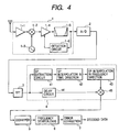
- OFDM modulation For digital terrestrial broadcasting, OFDM modulation is used and its details are specified, for example, in the ETS (European Telecommunication Standard). Based on this, main sections of a digital terrestrial broadcasting receiver are constructed as shown in FIG. 4. That is, in the digital terrestrial broadcasting receiver, a signal received from an antenna is converted to an intermediate frequency signal at a front end 1, supplied to an A/D converter 2 for an A/D conversion, then subjected to FFT (fast Fourier transform) calculation processing at an FFT calculation circuit 3, subjected to demodulation processing and the demodulated signal is equalized at an equalizer 4 and the equalized signal is demapped at a demapper 5, deinterleaved at a frequency deinterleave circuit 6, error-corrected at an error correction circuit 7 and then decoded.
- FFT fast Fourier transform
- the received signal from the antenna is amplified at an amplifier 1-1, the amplified output is frequency-mixed with an oscillation output from a local oscillator 1-3 by a mixer 1-2 and converted to an intermediate frequency signal, and the intermediate frequency signal is amplified at a variable gain amplifier 1-4, band-restricted at a band pass filter 1-5, sent to an A/D converter 2 and at the same time supplied to a detection circuit 1-6 where the signal is subjected to detection and AGC (automatic gain control) for controlling the gain of the variable gain amplifier 1-4 according to an AGC voltage based on the detection output.
- AGC automatic gain control
- ISDB-T Integrated Service Digital Broadcasting Terrestrial
- DVB-T Digital Video Broadcasting Terrestrial
- time deinterleave is further added besides frequency deinterleave.
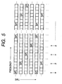
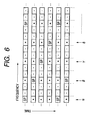
- part of a frame structure for both DVB-T and ISDB-T is constructed as schematically illustrated in FIG. 5 in such a way that one pilot carrier (carrier whose amplitude and phase are known) called “scattered pilot” (also denoted as "SP") is inserted every 12 carriers in the frequency direction and every 4 carriers in the time direction.
- SP pilot carrier
- Other carriers are data carriers.
- the number of carriers (in the frequency direction) per frame is 1705 (in 2K mode) and 6817 (in 8K mode) and the number of symbols (in the time direction) is 68.
- the number of carriers (in the frequency direction) is 1405 (in mode 1), 2809 (in mode 2) and 5617 (in mode 3) and the number of symbols (in the time direction) is 204.
- Data carriers are modulated with a maximum of 64 QAM. For this reason, the equalizer uses this SP to correct the amplitude and phase of each data carrier. However, since SP's are inserted in a scattered manner as shown above, an equalization coefficient between SPs is calculated through interpolation in order to correct amplitudes and phase shifts of data carriers based on a nearby SP.
- Equalization is performed by adopting a configuration in such a way that three blank sections between SPs each of which is inserted every 4 OFDM symbols in the time direction are interpolated based on the SPs in the time direction and thereby equalization coefficients at positions marked (*) in FIG. 6 are calculated as if SPs exist in all those sections in the time direction and similar interpolation is applied to the frequency direction based on this, equalization coefficients for parts marked (-) in FIG. 6 are calculated as if SPs or equalization coefficients exist in both the time direction and frequency direction.
- carrier columns in the time direction where SPs are inserted are marked with reference characters ⁇ , ⁇ , ⁇ , ⁇ , ....
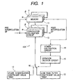
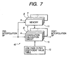
- SPs are extracted from a demodulated signal at an SP extraction circuit 41, interpolated based on the extracted SPs in the time direction at a time-direction SP interpolation circuit 42, and the interpolated simulated SPs in the time direction are regarded as equalization coefficients in the time direction, then interpolated based on the SPs in the time direction and equalization coefficients in the time direction at a frequency-direction SP interpolation circuit 43, the interpolated simulated SPs in the frequency direction are regarded as the equalization coefficients in the frequency direction and in this way SPs and equalization coefficients in the time direction and SPs and equalization coefficients in the frequency direction are obtained.
- the demodulated signal is delayed by a delay circuit 44 for compensating for delays in the processing times at the time-direction SP interpolation circuit 42 and the frequency-direction SP interpolation circuit 43 and the demodulated signal delayed by the delay circuit 44 is subjected to equalization processing at an equalization calculator 45 using SPs and equalization coefficients output from the frequency-direction SP interpolation circuit 43 and sent to the demapper 5.
- equalization coefficients between SPs in the time direction are conventionally calculated using a filter coefficient value (also denoted as "lowpass filter coefficient value”) of a digital low pass filter, see for example EP 1032169 .
- filter coefficient value also denoted as "lowpass filter coefficient value”
- interpolation using low pass filter coefficient values is performed with a configuration shown in FIG. 7, but in the case of interpolation using low pass filter coefficient values, the values of originally existing SPs themselves are possibly changed by interpolation calculations resulting in a problem that this may cause deterioration of the reception characteristics in the case where the reception mode is mobile reception.
- SPs before interpolation including blank parts shown in FIG. 5 in the OFDM frame extracted at the SP extraction circuit 41 are stored in memories 11 to calculate equalization coefficients in the time direction and the corresponding low pass filter coefficient values prestored in the low pass filter coefficient value table 12 and the SPs read from the memory 11 are subjected to a convolution calculation at convolution calculation circuits 13 to obtain equalization coefficients.
- memories 11 and convolution calculation circuits 13 are provided in a one-to-one correspondence with the carrier columns ⁇ , ⁇ , ⁇ , ⁇ , ... in the time direction shown in FIG. 5.
- the number of carrier columns in the case of 2K mode in DVB-T is ([1705/3] + 1) and [.] is a Gaussian symbol and 1705 is divided by 3 because a carrier column with an SP inserted exists every 3 carriers in the frequency direction.
- reference numeral 11( ⁇ ) denotes the memory 11 corresponding to the carrier column ⁇
- reference numeral 13( ⁇ ) denotes the convolution calculation circuit 13 corresponding to the carrier column ⁇
- reference character n denotes a SPs and equalization coefficients inserted in the carrier column ⁇ .
- SP1, 0, 0, 0, SP2, 0, 0, 0, SP3, 0, 0, 0, ... are sequentially stored in the memory 11( ⁇ ).
- SP1, SP2 and SP3 are sequentially numbered from the top for SPs of the carrier column ⁇ described in FIG. 5 and 0 denotes a section to be interpolated.
- the low pass filter coefficient table 12 prestores low pass filter coefficient values b0, b1, ..., b5 (low pass filter coefficient values at center address positions), ..., b9, b10 at addresses C0, C1, ..., C9 and C10 as illustrated in FIG. 8.
- the SPs in the time direction (carrier column ⁇ ) stored in the memory 11( ⁇ ) and low pass filter coefficient values are subjected to convolution calculation at symbol intervals and SPs indicated by reference character n shown in FIG.
- SP3-3, SP3-2, SP3-1, SP3', SP2-3, SP2-2, SP2-1, SP2', SP1-3, SP1-2, SP1-1, SP1' are calculated in association with, ..., SP1, 0, 0, 0, SP2, 0, 0, 0, SP3, 0, 0, 0, ..., stored in the memory 11( ⁇ ).
- SP1, 0, 0, 0, SP2, 0, 0, 0, SP3, 0, 0, ... have a one-to-one correspondence with SP1', SP1-1, SP1-2, SP1-3, SP2', SP2-1, SP2-2, SP2-3, SP3', SP3-1, SP3-2, SP3-3, ....
- SP2' that corresponds to SP2 equalization coefficients SP2-1, SP2-2 and SP2-3 interpolated between SP2 and SP3 and SP3' that corresponds to SP3, which are equalization coefficient calculation results, are as follows:
- SP ⁇ 2 - 1 SP ⁇ 1 ⁇ b ⁇ 0 + SP ⁇ 2 ⁇ b ⁇ 4 + SP ⁇ 3 ⁇ b ⁇ 8
- SP ⁇ 2 - 2 SP ⁇ 2 ⁇ b ⁇ 3 + SP ⁇ 3 ⁇ b ⁇ 7
- SP ⁇ 2 - 3 SP ⁇ 2 ⁇ b ⁇ 2 + SP ⁇ 3 ⁇ b ⁇ 6 + SP ⁇ 4 ⁇ b ⁇ 10
- SP ⁇ 3 ⁇ ⁇ SP ⁇ 2 ⁇ b ⁇ 1 + SP ⁇ 3 ⁇ b ⁇ 5 + SP ⁇ 4 ⁇ b ⁇ 9
- SP2' after interpolation becomes almost an approximate value of SP2 before interpolation (pre-interpolation SP2), but it may be a value different from SP2.
- SP3' after interpolation post-interpolation SP3'
- SP3 before interpolation pre-interpolation SP3
- the equalizer according to the present invention is an equalizer for a digital terrestrial broadcasting receiver that receives an OFDM-modulated signal, including extraction means for extracting a scattered pilot in a time direction during demodulation output at the digital terrestrial broadcasting receiver, a spline interpolation coefficient value table that stores spline interpolation coefficient values in which a spline interpolation coefficient value in the central position is 1 while spline interpolation coefficient values at positions ⁇ 4n (n: natural number) from the central position are 0, a low pass filter coefficient value table that stores low pass filter coefficient values, decision means for deciding whether the reception mode of the digital terrestrial broadcasting receiver is fixed-position reception or mobile reception, a changeover switch that selects, when the decision means decides that the reception mode is fixed-position reception, a low pass filter coefficient value read from the low pass filter coefficient value table and selects, when the decision means decides that the reception mode is mobile reception, a spline interpolation coefficient value read from the spline interpolation coefficient value table and
- the equalizer of the present invention when the reception mode is fixed-position reception, a low pass filter count value with a passage bandwidth fixed is used for SP interpolation and when the reception mode is mobile reception, a spline interpolation coefficient value is used for SP interpolation, and therefore favorable reception characteristics are obtained in both cases where the reception mode is fixed-position reception and where the reception mode is mobile reception.
- the spline interpolation coefficient value in the central position is 1 and the spline interpolation coefficient values at positions ⁇ 4n (n: natural number) from the above-described central position are 0, and therefore there is no change between the value of the scattered pilot before interpolation and value of the scattered pilot after interpolation, and furthermore since the equalization coefficient value between the scattered pilot in the time direction and the following scattered pilot is the result of a convolutional calculation between original scattered pilot pilots before and after the scattered pilot and spline interpolation coefficient value, the case with interpolation using the spline interpolation coefficient value is essentially the same as the case with interpolation using a low pass filter coefficient value, which makes the present invention an equalizer with an excellent reception characteristic also for mobile reception.
- the decision means can also be adapted so as to calculate power of a scattered pilot at a predetermined position extracted from the extraction means and decide, when a variation of the calculated power is equal to or greater than a predetermined value, that the reception mode is mobile reception and decide, when the variation of the calculated power is smaller than the predetermined value, that the reception mode is fixed-position reception, or decide, when a variation of an AGC voltage of the digital terrestrial broadcasting receiver is equal to or greater than a predetermined value, that the reception mode is mobile reception and decide, when the variation of the AGC voltage is smaller than the predetermined value, that the reception mode is fixed-position reception, or decide, when a variation of the sum total of all carrier levels calculated from the FFT-processed output is equal to or greater than a predetermined value, that the reception mode is mobile reception and decide, when the variation of the sum total of all carrier levels is smaller than the predetermined value, that the reception mode is fixed-position reception.
- FIG. 1 is a block diagram showing a configuration of an SP interpolation circuit in a time direction of an equalizer according to an embodiment of the present invention
- FIG. 2 is a schematic view illustrating an operation of the SP interpolation circuit in the time direction of the equalizer according to the embodiment of the present invention.
- a time-direction SP interpolation circuit 42A is used instead of the time-direction SP interpolation circuit 42.
- the time-direction SP interpolation circuit 42A is shown in contrast to the time-direction SP interpolation circuit 42 shown in FIG. 7 and the same components as those in the time-direction SP interpolation circuit 42 are assigned the same reference numerals.
- the time-direction SP interpolation circuit 42A stores in the memories 11 SPs before interpolation including the blank parts shown in FIG. 5 in an OFDM frame extracted by the SP extraction circuit 41 and extracts either one of a low pass filter count value in a low pass filter count value table 12 or a spline interpolation coefficient value prestored in a spline interpolation coefficient value table 17 through a changeover switch 16 to calculate equalization coefficients in the time direction.
- the memories 11 and convolution calculation circuits 13 are provided in a one-to-one correspondence with the carrier columns ⁇ , ⁇ , ⁇ , ⁇ , ..., in the time direction shown in FIG. 5 as in the case of the time-direction SP interpolation circuit 42.
- An SP at a predetermined position read from the memory 11, for example, an SP at the first position on the carrier column ⁇ is read, then power of the SP is calculated by a power calculation circuit 14, a variation in the calculated power is decided by a variation decision circuit 15, and when the variation is decided to be equal to or greater than a predetermined decision value, the changeover switch 16 supplies a spline interpolation coefficient value from the spline interpolation coefficient value table 17 to the convolutional calculation circuit 13 to obtain an equalization coefficient through spline interpolation.
- the changeover switch 16 supplies a coefficient value from the low pass filter coefficient value table 12 to the convolution calculation circuit 13 to obtain an equalization coefficient according to the low pass filter count value.
- the power calculation circuit 14 can calculate whether the reception mode is fixed-position reception or mobile reception, and therefore the power calculation circuit 14 and variation decision circuit 15 constitute decision means for deciding whether the reception mode is fixed-position reception or mobile reception. Furthermore, since an SP is a complex number, the power calculation circuit 14 can calculate power of the SP by squaring the SP.
- the equalizer according to this embodiment of the present invention has the same configuration as that of the equalizer 4 shown in FIG. 4 except that it is provided with the time-direction SP interpolation circuit 42A instead of the time-direction SP interpolation circuit 42.
- the time-direction SP interpolation circuit 42A calculates an equalization coefficient in the time direction based on an SP in the time direction
- the frequency-direction SP interpolation circuit 43 interpolates equalization coefficients in the frequency direction based on the SPs and equalization coefficients in the time direction
- the equalization calculator 45 carries out equalization processing on the demodulated signal using SPs and equalization coefficients in the time direction, SPs and equalization coefficients in the frequency direction and outputs the signal to the demapper 5.
- the demodulated signal is also delayed by the delay circuit 44 for compensating for the delay in the processing time by the time-direction SP interpolation circuit 42A and the frequency-direction SP interpolation circuit 43 and then subjected to equalization processing.
- Reference numeral 11( ⁇ ) denotes the memory 11 that corresponds to the carrier column ⁇
- reference numeral 13(a) denotes the convolution calculation circuit 13 that corresponds to the carrier column ⁇
- reference character p denotes SPs and equalization coefficients to be inserted in the carrier column ⁇ .
- the memory 11( ⁇ ) sequentially stores SP1, 0, 0, 0, SP2, 0, 0, 0, SP3, 0, 0, 0, ..., as in the case shown in FIG. 8.
- SP1, SP2 and SP3 are sequentially numbered from the top for SPs of the carrier column ⁇ described in FIG. 5 and 0 denotes a section to be interpolated.
- Interpolation according to low pass filter coefficient values is the same as the above-described conventional case, and therefore explanations thereof are omitted and only interpolation according to spline interpolation coefficient values will be explained.
- the spline interpolation coefficient value table 17 prestores spline interpolation coefficient values k0, k1, ..., k5 (spline interpolation coefficient values at center address positions), ..., k9, k10 at addresses C0, C1, ..., C9 and C10 as illustrated in FIG. 2.
- the SPs in the time direction (carrier column ⁇ ) stored in the memory 11( ⁇ ) and spline interpolation coefficient values are subjected to convolutional calculation at symbol intervals and SPs and equalization coefficients, ..., SP3-3, SP3-2, SP3-1, SP3', SP2-3, SP2-2, SP2-1, SP2', SP1-3, SP1-2, SP1-1, SP1' indicated by reference numeral p shown in FIG.
- SP1, 0, 0, 0, SP2, 0, 0, SP3, 0, 0, 0, ... are calculated in association with, ..., SP1, 0, 0, 0, SP2, 0, 0, SP3, 0, 0, 0, ... stored in the memory 11( ⁇ ).
- SP1, 0, 0, SP2, 0, 0, SP3, 0, 0, ... also have a one-to-one correspondence with SP1', SP1-1, SP1-2, SP1-3, SP2', SP2-1, SP2-2, SP2-3, SP3', SP3-1, SP3-2, SP3-3, ....
- spline interpolation coefficient value k5 at the center address position is set to 1
- n is a natural number.
- the spline interpolation coefficient values at address positions away from the center address position by 4n symbols are set to 0 because SPs in the time direction are inserted every fourth SP in the time direction.
- SP2' that corresponds to SP2
- equalization coefficients SP2-1, SP2-2 and SP2-3 interpolated between SP2 and SP3 and SP3' that corresponds to SP3 which are equalization results in the case of spline interpolation coefficients, are as follows:
- SP2' SP2
- the value of the SP itself does not change.
- the equalizer according to this embodiment of the present invention is an equalizer with excellent mobile characteristics.
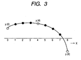
- a, b, c and d are expressions which are obtained based on real points. Suppose these expressions are expressed as fa, fb, fc and fd.
- y x fa y 0 , y 4 , y 8 ⁇ x 3 + fb y 0 , y 4 , y 8 ⁇ x 2 + fc y 0 , y 4 , y 8 ⁇ x + fd y 0 , y 4 , y 8 End point processing will be omitted.
- k 0 a 3
- k 1 0
- k 2 a 5
- k 2 a 6
- k 4 b 3
- k 5 1
- k 6 b 5
- k 7 b 6
- k 8 c 3
- k 9 0
- k 10 c 5
- k 11 c 6
- the equalizer of this embodiment of the present invention when the reception mode is fixed-position reception, a low pass filter count value with a passage bandwidth fixed is used for SP interpolation, and when the reception mode is mobile reception, a spline interpolation coefficient value is used for SP interpolation, and therefore it is possible to obtain favorable reception characteristics in both cases where the reception mode is fixed-position reception and where the reception mode is mobile reception.
- whether the reception mode is fixed-position reception or mobile reception is decided based on the power of SPs.
- the equalizer according to the present invention switches between interpolation according to low pass filter coefficient values and interpolation according to spline interpolation coefficient values depending on whether the reception mode is fixed-position reception or mobile reception, and can thereby improve reception characteristics in both cases where the reception mode is fixed-position reception and where the reception mode is mobile reception.
Landscapes
- Engineering & Computer Science (AREA)
- Physics & Mathematics (AREA)
- Nonlinear Science (AREA)
- Power Engineering (AREA)
- Computer Networks & Wireless Communication (AREA)
- Signal Processing (AREA)
- Cable Transmission Systems, Equalization Of Radio And Reduction Of Echo (AREA)
- Noise Elimination (AREA)
Claims (4)
- Ausgleichsvorrichtung (equalizer) zur Verwendung in einem Empfänger für digitale terrestrische Übertragung, welcher ein durch orthogonales Frequenzteilungsmultiplexen, OFDM (orthogonal frequency division multiplexing), moduliertes Signal empfängt, wobei die Ausgleichsvorrichtung Folgendes umfasst:eine Extraktionseinrichtung (41) zum Extrahieren gestreuter Piloten (scattered pilots), welche alle vier OFDM-Symbole angeordnet sind, in der Zeitrichtung in einem Demodulationsausgang des Empfängers für digitale terrestrische Übertragung;wobei die Ausgleichsvorrichtung dadurch gekennzeichnet ist, dass sie weiterhin umfasst
eine Tabelle (17) für Spline-Interpolationskoeffizientenwerte, welche Spline-Interpolationskoeffizientenwerte speichert, wobei die Tabelle eine ungerade Anzahl der Koeffizientenwerte enthält, so dass der Koeffizientenwert an der zentralen Position der Tabelle (17) auf 1 gesetzt wird und Koeffizientenwerte an von der zentralen Position um ± 4n entfernten Positionen, mit n als einer natürlichen Zahl, auf 0 gesetzt werden;
eine Tabelle (12) für Tiefpassfilterkoeffizientenwerte, welche Tiefpassfilterkoeffizientenwerte speichert;
eine Entscheidungseinrichtung (15), welche entscheidet, ob der Empfangsmodus des Empfängers für digitale terrestrische Übertragung Festpositionsempfang oder Mobilempfang ist;
einen Umstellschalter (16), welcher so arbeitet, dass er einen aus der Tabelle für Tiefpassfilterkoeffizientenwerte ausgelesenen Tiefpassfilterkoeffizientenwert wählt, wenn die Entscheidungseinrichtung entscheidet, dass der Empfangsmodus Festpositionsempfang ist, und dass er einen aus der Tabelle für Spline-Interpolationskoeffizientenwerte ausgelesenen Spline-Interpolationskoeffizientenwert wählt, wenn die Entscheidungseinrichtung entscheidet, dass der Empfangsmodus Mobilempfang ist; und
einen Faltungsberechnungsschaltkreis (13), welcher eine Faltungsberechnung zwischen den extrahierten gestreuten Piloten in der Zeitrichtung und durch den Umstellschalter ausgegebenen Koeffizientenwerten ausführt, um Ausgleichskoeffizienten zu erhalten,
wobei der demodulierte Ausgang ausgeglichen wird (45) auf Grundlage der gestreuten Piloten in der Zeitrichtung und der erhaltenen Ausgleichskoeffizienten. - Ausgleichsvorrichtung nach Anspruch 1, bei der die Entscheidungseinrichtung die Stärke (power) eines von der Extraktionseinrichtung an einer vorbestimmten Position extrahierten gestreuten Piloten berechnet, und bei der die Entscheidungseinrichtung entscheidet, dass der Empfangsmodus Mobilempfang ist, wenn eine Variation der berechneten Stärke gleich einem vorbestimmten Wert oder größer als derselbe ist, und entscheidet, dass der Empfangsmodus Festpositionsempfang ist, wenn die Variation der berechneten Stärke kleiner ist als der vorbestimmte Wert.
- Ausgleichsvorrichtung nach Anspruch 1, bei der die Entscheidungseinrichtung entscheidet, dass der Empfangsmodus Mobilempfang ist, wenn eine Variation einer AGC-Spannung des Empfängers für digitale terrestrische Übertragung gleich einem vorbestimmten Wert oder größer als derselbe ist, und die Entscheidungseinrichtung entscheidet, dass der Empfangsmodus Festpositionsempfang ist, wenn die Variation einer AGC-Spannung kleiner ist als der vorbestimmte Wert.
- Ausgleichsvorrichtung nach Anspruch 1, bei der die Entscheidungseinrichtung entscheidet, dass der Empfangsmodus Mobilempfang ist, wenn eine Variation der aus dem FFTverarbeiteten Ausgang berechneten Gesamtsumme aller Trägerniveaus gleich einem vorbestimmten Wert oder größer als derselbe ist, und die Entscheidungseinrichtung entscheidet, dass der Empfangsmodus Festpositionsempfang ist, wenn die Variation der Gesamtsumme aller Trägerniveaus kleiner ist als der vorbestimmte Wert.
Applications Claiming Priority (2)
| Application Number | Priority Date | Filing Date | Title |
|---|---|---|---|
| JP2002084909 | 2002-03-26 | ||
| JP2002084909A JP3870116B2 (ja) | 2002-03-26 | 2002-03-26 | 等化器 |
Publications (3)
| Publication Number | Publication Date |
|---|---|
| EP1349335A2 EP1349335A2 (de) | 2003-10-01 |
| EP1349335A3 EP1349335A3 (de) | 2006-10-18 |
| EP1349335B1 true EP1349335B1 (de) | 2007-09-19 |
Family
ID=27800418
Family Applications (1)
| Application Number | Title | Priority Date | Filing Date |
|---|---|---|---|
| EP20030006240 Expired - Lifetime EP1349335B1 (de) | 2002-03-26 | 2003-03-20 | Auswahl eines Interpolationsverfahrens zum Mehrträgerempfang |
Country Status (3)
| Country | Link |
|---|---|
| EP (1) | EP1349335B1 (de) |
| JP (1) | JP3870116B2 (de) |
| DE (2) | DE03006240T1 (de) |
Families Citing this family (10)
| Publication number | Priority date | Publication date | Assignee | Title |
|---|---|---|---|---|
| JP3952203B2 (ja) | 2003-10-27 | 2007-08-01 | カシオ計算機株式会社 | Ofdm復調装置、ofdm復調用集積回路、及びofdm復調方法 |
| CN1989693B (zh) * | 2004-07-23 | 2012-03-14 | 天龙马兰士集团有限公司 | 音频信号输出装置 |
| JP2006042025A (ja) | 2004-07-28 | 2006-02-09 | Casio Comput Co Ltd | Ofdm信号復調回路及びofdm信号復調方法 |
| DE602006004975D1 (de) * | 2005-03-01 | 2009-03-12 | Panasonic Corp | OFDM-Empfänger und Empfangsverfahren |
| JP4744991B2 (ja) * | 2005-09-06 | 2011-08-10 | 株式会社ディーアンドエムホールディングス | オーディオ信号出力装置 |
| JP2007093677A (ja) * | 2005-09-27 | 2007-04-12 | D & M Holdings Inc | オーディオ信号出力装置 |
| JP4704872B2 (ja) * | 2005-09-27 | 2011-06-22 | 株式会社ディーアンドエムホールディングス | オーディオ信号出力装置 |
| GB2444100B (en) | 2006-11-24 | 2009-10-28 | Imagination Tech Ltd | Channel estimation and equalization in ofdm receivers |
| JP2008199499A (ja) * | 2007-02-15 | 2008-08-28 | Sanyo Electric Co Ltd | Ofdm信号等化装置及び方法 |
| CN105634439B (zh) * | 2015-12-22 | 2018-08-14 | 熊猫电子集团有限公司 | 一种异步成形滤波器设计方法 |
Family Cites Families (2)
| Publication number | Priority date | Publication date | Assignee | Title |
|---|---|---|---|---|
| KR100224864B1 (ko) * | 1997-08-20 | 1999-10-15 | 윤종용 | Ofdm 수신기를 위한 등화 방법과 등화기 |
| FR2790343B1 (fr) * | 1999-02-26 | 2001-06-01 | Thomson Csf | Systeme pour l'estimation du gain complexe d'un canal de transmission |
-
2002
- 2002-03-26 JP JP2002084909A patent/JP3870116B2/ja not_active Expired - Fee Related
-
2003
- 2003-03-20 EP EP20030006240 patent/EP1349335B1/de not_active Expired - Lifetime
- 2003-03-20 DE DE2003006240 patent/DE03006240T1/de active Pending
- 2003-03-20 DE DE2003616374 patent/DE60316374T2/de not_active Expired - Lifetime
Also Published As
| Publication number | Publication date |
|---|---|
| DE60316374D1 (de) | 2007-10-31 |
| EP1349335A2 (de) | 2003-10-01 |
| DE03006240T1 (de) | 2004-04-15 |
| JP2003283392A (ja) | 2003-10-03 |
| EP1349335A3 (de) | 2006-10-18 |
| DE60316374T2 (de) | 2008-01-24 |
| JP3870116B2 (ja) | 2007-01-17 |
Similar Documents
| Publication | Publication Date | Title |
|---|---|---|
| JP4728227B2 (ja) | Ofdm受信装置及びofdm受信方法 | |
| US7450653B2 (en) | Digital broadcast signal receiving apparatus and method | |
| US7724694B2 (en) | Doppler frequency calculating apparatus and method and OFDM demodulating apparatus | |
| US8045945B2 (en) | Reception apparatus, reception method and program | |
| JP2003249907A (ja) | Ofdm方式の伝送装置 | |
| JP3110423B1 (ja) | 周波数選択性妨害に対応する誤り訂正装置 | |
| US8155223B2 (en) | Receiving device, receiving method, and program | |
| EP1349335B1 (de) | Auswahl eines Interpolationsverfahrens zum Mehrträgerempfang | |
| JP2004228853A (ja) | Ofdm受信装置及びデータ復調方法 | |
| US8175204B2 (en) | Receiving device, signal processing method, and program | |
| EP2169891A2 (de) | Informationsprozessor sowie entsprechendes Verfahren, entsprechende Anzeige und entsprechendes Programm | |
| US20090060072A1 (en) | Decoding method for receiving ofdm signals, and decoding apparatus and receiving apparatus using the same | |
| JP4819651B2 (ja) | Ofdm信号の伝送路特性推定手段と補正手段及びそれを用いた装置 | |
| JP2005191662A (ja) | Ofdm信号の復調方法 | |
| JP2008283588A (ja) | 受信装置及び受信信号増幅率設定方法 | |
| JP2009290579A (ja) | Ofdm受信装置 | |
| JP2009044443A (ja) | 受信装置及び受信方法 | |
| JP3870113B2 (ja) | 等化器 | |
| JP2004140739A (ja) | Ofdm受信装置 | |
| JP2007266761A (ja) | 受信装置 | |
| JP2008288681A (ja) | 等化処理装置、等化処理方法、及びデジタル信号受信機 | |
| JP2006279346A (ja) | 受信装置 |
Legal Events
| Date | Code | Title | Description |
|---|---|---|---|
| PUAI | Public reference made under article 153(3) epc to a published international application that has entered the european phase |
Free format text: ORIGINAL CODE: 0009012 |
|
| AK | Designated contracting states |
Kind code of ref document: A2 Designated state(s): AT BE BG CH CY CZ DE DK EE ES FI FR GB GR HU IE IT LI LU MC NL PT RO SE SI SK TR |
|
| AX | Request for extension of the european patent |
Extension state: AL LT LV MK |
|
| EL | Fr: translation of claims filed | ||
| DET | De: translation of patent claims | ||
| PUAL | Search report despatched |
Free format text: ORIGINAL CODE: 0009013 |
|
| AK | Designated contracting states |
Kind code of ref document: A3 Designated state(s): AT BE BG CH CY CZ DE DK EE ES FI FR GB GR HU IE IT LI LU MC NL PT RO SE SI SK TR |
|
| AX | Request for extension of the european patent |
Extension state: AL LT LV MK |
|
| 17P | Request for examination filed |
Effective date: 20070122 |
|
| GRAP | Despatch of communication of intention to grant a patent |
Free format text: ORIGINAL CODE: EPIDOSNIGR1 |
|
| RIC1 | Information provided on ipc code assigned before grant |
Ipc: H04L 27/26 20060101ALN20070417BHEP Ipc: H04L 25/02 20060101AFI20070417BHEP Ipc: H04L 25/03 20060101ALN20070417BHEP |
|
| AKX | Designation fees paid |
Designated state(s): DE FR GB |
|
| GRAS | Grant fee paid |
Free format text: ORIGINAL CODE: EPIDOSNIGR3 |
|
| GRAA | (expected) grant |
Free format text: ORIGINAL CODE: 0009210 |
|
| AK | Designated contracting states |
Kind code of ref document: B1 Designated state(s): DE FR GB |
|
| REG | Reference to a national code |
Ref country code: GB Ref legal event code: FG4D |
|
| REF | Corresponds to: |
Ref document number: 60316374 Country of ref document: DE Date of ref document: 20071031 Kind code of ref document: P |
|
| EN | Fr: translation not filed | ||
| PLBE | No opposition filed within time limit |
Free format text: ORIGINAL CODE: 0009261 |
|
| STAA | Information on the status of an ep patent application or granted ep patent |
Free format text: STATUS: NO OPPOSITION FILED WITHIN TIME LIMIT |
|
| ET | Fr: translation filed | ||
| REG | Reference to a national code |
Ref country code: FR Ref legal event code: EERR Free format text: CORRECTION DE BOPI 08/21 - BREVETS EUROPEENS DONT LA TRADUCTION N A PAS ETE REMISE A L INPI. IL Y A LIEU DE SUPPRIMER : LA MENTION DE LA NON-REMISE. LA REMISE DE LA TRADUCTION EST PUBLIEE DANS LE PRESENT BOPI. |
|
| 26N | No opposition filed |
Effective date: 20080620 |
|
| PG25 | Lapsed in a contracting state [announced via postgrant information from national office to epo] |
Ref country code: FR Free format text: LAPSE BECAUSE OF FAILURE TO SUBMIT A TRANSLATION OF THE DESCRIPTION OR TO PAY THE FEE WITHIN THE PRESCRIBED TIME-LIMIT Effective date: 20080523 |
|
| REG | Reference to a national code |
Ref country code: DE Ref legal event code: R082 Ref document number: 60316374 Country of ref document: DE Representative=s name: LEINWEBER & ZIMMERMANN, DE |
|
| REG | Reference to a national code |
Ref country code: DE Ref legal event code: R082 Ref document number: 60316374 Country of ref document: DE Representative=s name: LEINWEBER & ZIMMERMANN, DE Effective date: 20120430 Ref country code: DE Ref legal event code: R081 Ref document number: 60316374 Country of ref document: DE Owner name: JVC KENWOOD CORPORATION, JP Free format text: FORMER OWNER: KABUSHIKI KAISHA KENWOOD, HACHIOUJI, JP Effective date: 20120430 Ref country code: DE Ref legal event code: R081 Ref document number: 60316374 Country of ref document: DE Owner name: JVC KENWOOD CORPORATION, YOKOHAMA-SHI, JP Free format text: FORMER OWNER: KABUSHIKI KAISHA KENWOOD, HACHIOUJI, TOKIO/TOKYO, JP Effective date: 20120430 |
|
| REG | Reference to a national code |
Ref country code: FR Ref legal event code: TP Owner name: JVC KENWOOD CORPORATION, JP Effective date: 20120705 |
|
| REG | Reference to a national code |
Ref country code: FR Ref legal event code: PLFP Year of fee payment: 14 |
|
| REG | Reference to a national code |
Ref country code: FR Ref legal event code: PLFP Year of fee payment: 15 |
|
| REG | Reference to a national code |
Ref country code: FR Ref legal event code: PLFP Year of fee payment: 16 |
|
| PGFP | Annual fee paid to national office [announced via postgrant information from national office to epo] |
Ref country code: GB Payment date: 20180314 Year of fee payment: 16 Ref country code: DE Payment date: 20180306 Year of fee payment: 16 |
|
| PGFP | Annual fee paid to national office [announced via postgrant information from national office to epo] |
Ref country code: FR Payment date: 20180223 Year of fee payment: 16 |
|
| REG | Reference to a national code |
Ref country code: DE Ref legal event code: R119 Ref document number: 60316374 Country of ref document: DE |
|
| GBPC | Gb: european patent ceased through non-payment of renewal fee |
Effective date: 20190320 |
|
| PG25 | Lapsed in a contracting state [announced via postgrant information from national office to epo] |
Ref country code: GB Free format text: LAPSE BECAUSE OF NON-PAYMENT OF DUE FEES Effective date: 20190320 Ref country code: DE Free format text: LAPSE BECAUSE OF NON-PAYMENT OF DUE FEES Effective date: 20191001 |
|
| PG25 | Lapsed in a contracting state [announced via postgrant information from national office to epo] |
Ref country code: FR Free format text: LAPSE BECAUSE OF NON-PAYMENT OF DUE FEES Effective date: 20190331 |