EP1564694A2 - Machine de vente - Google Patents
Machine de vente Download PDFInfo
- Publication number
- EP1564694A2 EP1564694A2 EP05250118A EP05250118A EP1564694A2 EP 1564694 A2 EP1564694 A2 EP 1564694A2 EP 05250118 A EP05250118 A EP 05250118A EP 05250118 A EP05250118 A EP 05250118A EP 1564694 A2 EP1564694 A2 EP 1564694A2
- Authority
- EP
- European Patent Office
- Prior art keywords
- commodity
- display
- size
- image
- actual
- Prior art date
- Legal status (The legal status is an assumption and is not a legal conclusion. Google has not performed a legal analysis and makes no representation as to the accuracy of the status listed.)
- Withdrawn
Links
Images





Classifications
-
- G—PHYSICS
- G06—COMPUTING OR CALCULATING; COUNTING
- G06F—ELECTRIC DIGITAL DATA PROCESSING
- G06F3/00—Input arrangements for transferring data to be processed into a form capable of being handled by the computer; Output arrangements for transferring data from processing unit to output unit, e.g. interface arrangements
- G06F3/01—Input arrangements or combined input and output arrangements for interaction between user and computer
- G06F3/048—Interaction techniques based on graphical user interfaces [GUI]
- G06F3/0487—Interaction techniques based on graphical user interfaces [GUI] using specific features provided by the input device, e.g. functions controlled by the rotation of a mouse with dual sensing arrangements, or of the nature of the input device, e.g. tap gestures based on pressure sensed by a digitiser
- G06F3/0488—Interaction techniques based on graphical user interfaces [GUI] using specific features provided by the input device, e.g. functions controlled by the rotation of a mouse with dual sensing arrangements, or of the nature of the input device, e.g. tap gestures based on pressure sensed by a digitiser using a touch-screen or digitiser, e.g. input of commands through traced gestures
- G06F3/04886—Interaction techniques based on graphical user interfaces [GUI] using specific features provided by the input device, e.g. functions controlled by the rotation of a mouse with dual sensing arrangements, or of the nature of the input device, e.g. tap gestures based on pressure sensed by a digitiser using a touch-screen or digitiser, e.g. input of commands through traced gestures by partitioning the display area of the touch-screen or the surface of the digitising tablet into independently controllable areas, e.g. virtual keyboards or menus
-
- G—PHYSICS
- G06—COMPUTING OR CALCULATING; COUNTING
- G06F—ELECTRIC DIGITAL DATA PROCESSING
- G06F3/00—Input arrangements for transferring data to be processed into a form capable of being handled by the computer; Output arrangements for transferring data from processing unit to output unit, e.g. interface arrangements
- G06F3/01—Input arrangements or combined input and output arrangements for interaction between user and computer
- G06F3/048—Interaction techniques based on graphical user interfaces [GUI]
- G06F3/0481—Interaction techniques based on graphical user interfaces [GUI] based on specific properties of the displayed interaction object or a metaphor-based environment, e.g. interaction with desktop elements like windows or icons, or assisted by a cursor's changing behaviour or appearance
- G06F3/0482—Interaction with lists of selectable items, e.g. menus
-
- G—PHYSICS
- G06—COMPUTING OR CALCULATING; COUNTING
- G06Q—INFORMATION AND COMMUNICATION TECHNOLOGY [ICT] SPECIALLY ADAPTED FOR ADMINISTRATIVE, COMMERCIAL, FINANCIAL, MANAGERIAL OR SUPERVISORY PURPOSES; SYSTEMS OR METHODS SPECIALLY ADAPTED FOR ADMINISTRATIVE, COMMERCIAL, FINANCIAL, MANAGERIAL OR SUPERVISORY PURPOSES, NOT OTHERWISE PROVIDED FOR
- G06Q20/00—Payment architectures, schemes or protocols
- G06Q20/08—Payment architectures
- G06Q20/20—Point-of-sale [POS] network systems
-
- G—PHYSICS
- G07—CHECKING-DEVICES
- G07F—COIN-FREED OR LIKE APPARATUS
- G07F9/00—Details other than those peculiar to special kinds or types of apparatus
- G07F9/02—Devices for alarm or indication, e.g. when empty; Advertising arrangements in coin-freed apparatus
Definitions
- the present invention relates to a vending machine for selling a commodity such as a canned beverage, a bottled beverage and a plastic-bottled beverage, and in particular to a vending machine provided with a display for displaying an image on a surface to purchasers.
- vending machines for selling a commodity such as a canned beverage, a bottled beverage and a plastic-bottled beverage
- a vending machine provided with a display for displaying commodity images of salable commodities on a surface to purchasers.
- This vending machine has a touch sensor for detecting a position which a finger has touched on a screen of the display and specifying a coordinate on the screen of the display.
- This vending machine determines whether or not any one of the commodity images is selected based on a detection signal from the touch sensor, and sells a selected commodity when a commodity selection was performed.
- This vending machine makes it possible to more easily perform works such as exchanges or changing positions of steric commodity samples made of plastics or the like placed in a conventional vending machine by setting or changing kinds and positions of the commodity images to be displayed on the display.
- the object of the present invention is to provide a vending machine which can give visual effect that is similar to or more than that a conventional commodity sample can give.
- the vending machine of the present invention comprises: a display for displaying an image; a touch sensor for detecting a position on a screen of the display at which a finger has touched and specifying a coordinate position on the screen; commodity image storage means for storing commodity images each of which corresponds to each of commodities available for sale; first commodity image display means for displaying the commodity images showing the commodities available for sale in a commodity sample display area of a sales image in a reduced size; commodity selection determination means for determining whether or not any one of the commodity images displayed in the commodity sample display area is selected based on a detection signal from the touch sensor; and second commodity image display means for, when a commodity is selected, displaying a commodity image of a selected commodity in a commodity information display area of the sales image in an actual size.
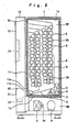
- FIGS. 1 to 9 show an embodiment of the present invention.
- FIG. 1 the front side of FIG. 1 will be assumed to be the front of the vending machine, the back side to be the back thereof, the left side to be the left thereof; and the right side to be the right thereof.
- a cabinet 1 forms a box shape and is provided with a heat-insulating chamber 1a therein, the front side of which is open.
- the heat-insulating chamber 1a is separated by heat-insulating partition panels (not shown) horizontally arranged into multiple unit chambers SR.
- each unit chamber SR there is arranged a commodity storage rack 2 consisting of a serpentine-type rack.
- the commodity storage rack 2 has a commodity replenishment part 2a at the upper part of the front side thereof; and commodities C, such as canned beverages, bottled beverages and plastic-bottled beverages, are laid down and piled in a meandering storage passage 2b.
- a vent mechanism 2c for droppingly discharging one of the stored commodities C onto a shoot plate 3.
- a sold-out detection sensor (not shown) for detecting presence/absence of the commodities C, in the each storage passage 2b.
- the commodity storage rack 2 is not limited to the serpentine-type rack, and it is possible to use any other type of rack capable of discharging one of the stored commodities like the serpentine-type rack.
- the each unit chamber SR is provided with the shoot plate 3 and a duct plate 4.
- an evaporator 5 among equipment constituting a refrigerator, an electric heater 6, an air blower for circulating cooling/humidifying air 7 and the like, and a space provided at the back side of the duct plate 4 is formed as a duct D.
- a temperature sensor (not shown) for detecting the temperature of commodities in the commodity storage rack 2 which are to be discharged soon.
- a machine chamber MR Below a bottom plate 1b of the heat-insulating chamber 1a, there is provided a machine chamber MR.
- a condenser 8 In the machine chamber MR, there are arranged a condenser 8, a compressor 9, expansion means (not shown) among the equipment constituting the refrigerator, an air blower for discharging exhaust heat 10 and the like.
- a heat-resisting inner door 11 for openably and closably covering the front opening.
- packings for keeping the commodity storage chamber (each unit chamber SR) air-tight when the inner door 11 is closed.
- the each unit chamber SR forms a separate heat-insulating space when the inner door 11 is closed.
- multiple window holes 11a are formed, each of which corresponds to the shoot plate 3 of the each unit chamber SR.
- the each window hole 11a is provided with a flap door 11b which is pushedly opened by a commodity C slipping down along the shoot plate 3.
- each unit chamber SR forms a separate heat-insulating space, and the each unit chamber SR is separately provided with the evaporator 5 and the electric heater 6. Accordingly, it is possible to select and perform any one three modes of cooling, humidifying and non-cooling/heating for the each unit chamber SR by a temperature adjusting/setting device 30 (see FIG. 3) to be described later.
- An outer door 12 is openably and closably provided at the front opening of the cabinet 1, and a dressed panel 18 is provided on the upper part of the surface of this outer door.
- the dressed panel 13 has a rectangular window hole 13a for exposing a screen of a liquid crystal display 14 and an advertisement section 13b for showing a product manufacturer's name, a product name and the like in characters.
- the liquid crystal display (hereinafter referred to as the LCD) 14 is for displaying a still image and/or a moving image in color, and it is arranged inside the dressed panel 13 in a manner that its screen is exposed through the window hole 13a.
- the LCD 14 has a predetermined size and a predetermined resolution, for example, the size of 18 inches and the resolution of 1280 ⁇ 1024 pixels.
- a well-known display for example, a cathode ray tube (CRT) display or a plasma display panel (PDP) may be used.
- CTR cathode ray tube
- PDP plasma display panel
- the screen of the LCD 14 is provided with a touch sensor 33 (see FIG. 3) for detecting a position on the screen at which a finger has touched and specifying a coordinate position on the screen, though it is not shown in FIG. 1 and FIG. 2.
- a touch sensor 33 for detecting a position on the screen at which a finger has touched and specifying a coordinate position on the screen, though it is not shown in FIG. 1 and FIG. 2.
- an infrared sensor which is constituted by light generation devices and light receiving devices arranged on the upper and lower edges and the right and left edges of the rectangular frame at regular intervals, as the touch sensor 33 as appropriate.
- a lock operation lever 15 At the front side of the outer door 12, there are arranged a lock operation lever 15, a coin insertion slot 16, a coin return lever 17, a bill insertion slot 18, a coin return port 19 and a commodity pick-up part 20 in die layout shown in FIG. 1.
- the lock operation lever 15 is for operating a lock mechanism (not shown) provided inside the outer door 12 and is enabled by a dedicated key.
- the commodity pack-up port 20 is provided with a flap door 21 which can be manually opened. Inside the flap door 21, there is provided a commodity receiving plate 22 for receiving a commodity C discharged from the flap door 11b.
- a first control section 23 mainly controls temperature and discharge of the commodities C
- a second control section 24 mainly controls display on the LCD 14 and external data communication.
- Each of the control sections 23 and 24 is constituted by a computer provided with a CPU, a RAM, a ROM and the like and can mutually perform data exchange require for control.
- one computer may comprise the first control section 23 and the second control section 24.
- a coin processor 25 for detecting, for the each storage passage 2b, presence/absence of the commodities C in the commodity storage rack 2 arranged in each unit chamber SR via a sold-out detection section (not shown), and the temperature sensor (not shown) for detecting the temperature of the commodities in the each unit chamber SR which are to be discharged soon via a temperature detection section (not shown).
- the coin processor 25 and the bill identifier 26 are arranged inside the outer door 12.
- the coin processor 25 performs reality check, counting and storage of coins inserted through the coin insertion slot 16, and it sends data about the amount of the inserted coins to the first control section 23.
- the bill identifier 26 performs reality check and storage of a bill inserted through the bill insertion slot 18, and it sends data about the amount of the inserted bill to the first control section 23.
- the discharge driving section 27 controls an operation of the vent mechanism 2c provided for the each commodity storage rack 2, more specifically, the operation of an actuator such as a solenoid used for the vent mechanism 2c, and it causes a predetermined vent mechanism 2c to operate based on a control signal from the first control section 23 to discharge a predetermined commodity.
- the compressor driving section 28 controls an operation of the compressor 9 constituting the refrigerator, more specifically, the operation of a motor for driving the compressor 9, and it drives the compressor based on a control signal from the first control section 23.
- the heater driving section 29 controls power distribution to the each electric heater 6, and it distributes power to a predetermined electric heater 6 based on a control signal from the first control section 23.
- the temperature adjusting/setting device 30 selects any one of the three modes described above for the each unit chamber SR. It is provided with push-button switches and the like for selecting the mode, and it sends data about a selected mode to the first control section 23.
- an LCD driving section 31 a coordinate detection section 32, a voice output section 34, a memory card adapter (hereinafter referred to as an MC adapter) 36, a modem 38 and a wireless communication section 40.
- an MC adapter memory card adapter
- the LCD driving section 31 controls display on the LCD 14 provided on the outer door 12, and it drives the LCD 14 to display a predetermined image, based on image data and a control signal from the second control section 24.
- the coordinate detection section 32 sends data about a coordinate of the screen to the second control section 24 based on a detection signal from the touch sensor 33. Since areas displayed on various images to be described later are set based on the coordinate on the screen of the LCD 14, it is possible to easily determine which area has been selected on the each image, from the data sent from the coordinate detection section 32 to the second control section 24.
- the voice output section 34 drives speakers 35 to output a predetermined voice, based on a voice signal and a control signal from the second control section 24. At least one speaker 35 is arranged on the each side of the LCD 14 inside the outer door 12 to give stereophonic effect.
- the MC adapter 36 enables a memory card (hereinafter referred to as the MC) 37 to be connected.
- the modem 38 is for performing data communication with an external server and the like with the use of a public tetephone line 39 and the like.
- the wireless communication section 40 is for performing wireless data communication with an external server and the like with the use of a mobile telephone network or a PHS network.
- Image data such as still images and moving images and character data which can be displayed on the LCD 14, and voice data to be outputted from the speakers 35 can be acquired into storage means such as a hard disk provided for the second control section 24 by means of data communication via the MC 37, the modem 38 or the wireless communication section 40, and these data can be arbitrarily updated.
- the image data, character data and voice data described above include display images, display characters and output voices to be provided when a standby image to be described later is displayed; display images (including multiple commodity images each of which corresponding to each of commodities available for sale), display characters and output voices to be provided when a sales image is displayed; display images, display characters and output voices to be provided when an advertisement image is displayed, display images, display characters and output voices to be provided when a campaign image is displayed; and display images, display characters and output voices to be provided when an inquiry image is displayed, the above images being to be described later.
- the each of commodity images stored in the storage means of the second control section 24 is created in a size (the number of horizontal pixels ⁇ the number of vertical pixels) that enables the commodity image to be displayed in its actual size on the LCD 14 with a predetermined size and a predetermined resolution.
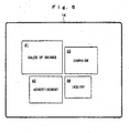
- step S1 of FIG. 4 When the vending machine is powered on, the standby image shown in FIG. 6 is displayed (step S1 of FIG. 4).
- selection areas are set on this standby image: a selection area A1 which includes "Sales of Drinks”, a selection area A2 which includes “Advertisement”, a selection area A3 which includes “Campaign”, and a selection area A4 which includes "Inquiry”.
- a selection area A1 which includes "Sales of Drinks”
- a selection area A2 which includes “Advertisement”
- a selection area A3 which includes “Campaign”
- selection area A4 which includes "Inquiry”.
- One each of the areas A1 to A4 an appropriate still image may be displayed with these words.
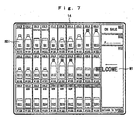
- the standby image is switched to the sales image shown in FIG. 7 (steps S2 and S4 of FIG. 4). If a finger touches the area A1 on the standby image, the standby image is switched to the sales image shown in FIG. 7 even when a coin or a bill is not inserted (steps S3 and S4 of FIG. 4).
- the following areas are set on this sales image in the layout shown in FIG. 7; a plurality of commodity sample display areas B1 to B30, an operation-state display area B31 for displaying either "On Sale” or "In Preparation", a paid-amount display area B32 for displaying the amount of coins and a bill inserted through the coin insertion slot 16 and the bill insertion slot 18, a commodity information display area B33 and a return area B34 for returning to the standby image.
- a commodity image showing a commodity available for sale is displayed in a reduced size.
- This reduced size commodity image SDI is obtained by reducing a commodity image stored in the storage means of the second control section 24 to 70 to 80%.
- a number indicating the commodity price is displayed below the reduced size commodity image SDI displayed in each of the commodity sample image areas B1 to B30.
- a temperature control indication word "COLD” or “HOT” is displayed, which indicates that the commodity is cooled or heated, respectively.
- the temperature control indication word may be displayed adjacent to the commodity price.
- the temperature control indicate word is "COLD”
- a cold blue color is used for the temperature control indication word or the background
- HAT a warm red color is used for the temperature control indication word or the background.
- an icon for a new commodity or campaign can be arbitrarily set and displayed.
- words such as "Being Cooled” and "Being Heated'' can be displayed in the commodity price display area.
- a message M1 such as "Welcome” is displayed while moving vertically, horizontally or obliquely, or motionlessly for a predetermined time, for example, for 0.5 seconds, as shown in FIG. 7 (step S5 of FIG.4).
- a voice appropriate to the message M1 may be outputted as necessary.
- a processing of embossing the reduced size commodity images SDI of the purchasable commodities is performed to differentiate the purchasable commodities from unpurchasable commodities.
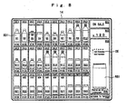
- the commodity image of the selected commodity is displayed in its actual size in the commodity information display area B38 so that the commodity appeals the purchaser.
- the commodity images stored in the storage means of the second control section 24 are created in a size that enables the commodity images to be displayed in their actual size on the LCD 14 with the predetermined size and the predetermined resolution. Therefore, if the commodity image of the selected commodity is immediately displayed in the commodity information display area B38, it is an actual size commodity image RSI.
- a commodity description CE for the selected commodity for example, contents, calorie, efficacy and the like are displayed in the same commodity information display area B38 while moving vertically, horizontally or obliquely, or motionlessly so that the commodity appeals to the purchaser more (step S8 of FIG. 4).
- step S9 of FIG. 4 it is determined whether or not the paid amount is the commodity price or above.
- step S9 If it is determined at step S9 that the paid amount does not satisfy the commodity price, for example, if the paid amount is somewhat insufficient, or insertion of a coin or a bill is not performed at this stage, then the process preceeds to step S6. That is, the slight movement of the reduced size commodity image SDI performed at step S7 and the display of the actual size commodity image RSI and the commodity description CE performed at step S8 are repeatedly performed in response to the commodity selection operation until the paid amount is the commodity price or above and the commodity is selected. In other words, by arbitrarily displaying the actual size commodity image RSI and the commodity description CE of the desired commodity, the purchaser can approppriately obtain informationn related to the commodity or information required purchase decision from the display.
- a message such as "The paid amount is insufficient" may be displayed while moving vertically or horizontally, or motionlessly as necessary until the paid amount reaches the commodity price.
- step S9 If it is determined at step S9 that the paid amount is the commodity price or above, then the vent mechanism 2c of the commodity storage rack 2 in which the selected commodity is stored is operated to discharge the commodity (step S11 of FIG. 4).
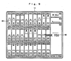
- a message M2 such as "Thank you” is displayed while moving vertically, horizontally or obliquely, or motionlessly for a predetermined time, for example, for 0.5 seconds, as shown in FIG. 9 (step S12 of FIG. 4).
- the sales image is returned to the standby image.
- a voice appropriate to the message M2 may be outputted as necessary.
- the paid amount is the commodity price or above at step S2, it means that the discharge of the commodity at step S11 is performed in response to the first commodity selection at step S6.
- the slight movement of the reduced size commodity image SDI at step S7 and the display of the actual size commodity image RSI and the commodity description CE at step S8 are performed only instantaneously.
- a purchase decision area B35 shown by a dashed line in FIG. 8 may be displayed in the commodity information display area B38 after step S9, and step S10 of determining whether or not a purchase decision has been made, which is shown by a dashed line in FIG. 4, may be provided.
- step S10 of determining whether or not a purchase decision has been made
- the standby image shown in FIG. 6 When the standby image shown in FIG. 6 is displayed, if a finger touches the area A2 on this image though a coin or a bill has not been inserted, the standby image is switched to an advertisement image (not shown) (steps S13 and S14 of FIG. 5).
- one or more selection areas are set which include a still image enabling an advertisement film to be recognized.
- the advertisement film (moving image) corresponding to the area is read from the storage means of the second control section 24, and it is played back with a voice accompanied (steps S15 and S16 of FIG. 5)
- step S17 of FIG. 5 When the playback of the specified advertisement film is completed, or when a finger touches a return area set at the corner of the display image while the advertisement film being played back, the image is returned to the standby image in response to a release instruction given based thereon (step S17 of FIG. 5).
- a nationally-telecast or a regionally limited advertisement film is mainly used as the above-described advertisement film.
- the displayable period of the advertisement film correspond to the period during which the film is telecast, it is possible to provide timely advertisement display.
- the corresponding advertisement film may be automatically deleted from the storage means. It is, of course, possible to use an advertisement film related to a local region where the vending machine is installed, for example, an advertisement film of a shopping area created by the shopping area, as the advertisement film described above.
- the standby image shown in FIG. 6 When the standby image shown in FIG. 6 is displayed, if a coin or a bill is not inserted and a finger touches the area A3 on this image, the standby image is switched to a campaign image (not shown) (steps S18 and S19 of FIG. 5).
- one or more selection areas are set which include a still image enabling contents of campaign to be recognized.
- a finger touches a predetermined selection area a campaign image (still image) corresponding to the area is read from the storage means of the second control section 24 and displayed.
- a voice for explaining the displayed campaign accompanies, the voice is also outputted (steps S20 and S21 af FIG. 5).
- step S22 of FIG. 5 When a predetermined time has elapsed after a specified campaign image is displayed, or when a finger touches a return area set at the corner of the display image while the campaign image being displayed, the image is returned to the standby image in response to a release instruction given based thereon (step S22 of FIG. 5).
- the campaign image described above an image of explanation is used, in which it is explained with the use of an image and words that a gift may be obtained in a drawing by collecting point stickers attached to predetennined commodities during a predetermined period and sending the point stickers attached to an application sheet, or that a gift may be obtained in a drawing by sending a post card on which an answer to a quiz is written during a predetermined period.
- the displayable period of the campaign image correspond to the above-mentioned predetermined period, it is possible to provide timely campaign display.
- the corresponding campaign image may be automatically deleted from the storage means. It is, of course, possible to use a campaign image related to a local region where the vending machine is installed, for example, a campaign image of a shopping area created by the shopping area, as the campaign image described above.
- a predetermined campaign image may be displayed when the standby image is switched to the campaign image.
- the image may be returned to the standby image in response to a release instruction given based thereon.
- the standby image shown in FIG. 6 When the standby image shown in FIG. 6 is displayed, if a coin or a bill is not inserted and a finger touches the area A4 on this image, the standby image is switched to an inquiry image (not shown) (steps S23 and S24 of FIG. 5).
- step S25 of FIG.5 When a predetermined time has elapsed after the inquiry image is displayed, or when a finger touches a return area set at the corner of the inquiry image while the inquiry image being displayed, the image is returned to the standby image in response to a release instruction given based thereon (step S25 of FIG.5).
- the commodity image of the selected commodity is displayed in the commodity information display area B33 of the sales image in its actual size.
- the commodity description CE including contents, calorie, efficacy and the like of the selected commodity together with the actual size commodity image RSI in the commodity information display area B33 of the sales image, it is possible to enhance recognition of the commodity by the purchaser by means of the commodity description CE and increase the purchaser's buying inclination.
- the displays of the actual size commodity image RSI and the commodity description CE can be arbitrarily performed in response to the commodity selection operation until the paid amount is the commodity price or above and the commodity is selected. Thereby, it is possible to provide information related to commodity or information required for purchase decision to the purchaser by means of such displays.
- the reduced size commodity image SDI of the selected commodity is slightly moved horizontally or vertically and the sound effect is generated. Thereby, it is possible to visually and audibly notify the purchaser that the predetermined commodity has been selected to confirm the selection.
- the sales image has been illustrated as one in the layout shown in FIG. 7 in the above description, the shape, the number and the arrangement of the commodity sample display areas B1 to B30 can be arbitrarily changed.
- the shape and the position of the commodity information display area B33 are not especially limited only if at least the actual size commodity image can be displayed therein.
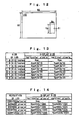
- FIG. 10 is a flowchart showing the first method.
- a commodity image corresponding to a seleted commodity is read from among multiple commodity images stored in the storage means of the second control section 24 (step ST1 of FIG. 10).
- step ST3 of FIG.10 a processing for changing the display size of commodity images is performed as described below based on the size and the resolution of the actual LCD so that the commodity images can be displayed in the commodity information display area B33 in their actual size.
- the size and the resolution of the actual LCD are the same as the reference size and resolution, for example, 18 inches and 1280 ⁇ 1024 pixels, then, by immediately displaying a commodity image (the number of horizontal pixels Xps ⁇ the number of vertical pixels Yps) stored in the storage means of the second control section 24 in the commodity information display area B33, this commodity image is displayed as the actual size commodity image RSI, as described above.
- the resolution of an actual LCD is the same as the reference resolution and its size is larger than the reference size, for example, 19 inches, 20 inches, 21 inches, 22 inches or 23 inches
- the size of the displayed commodity image is larger than its actual size.
- the resolution of an actual LCD is the same as the reference resolution and its size is smaller than the reference size, for example, 15 inches or 17 inches
- the size of the displayed commodity image is smaller than its actual size.
- the display size of the commodity image CI (the number of horizontal pixels Xp ⁇ the number of vertical pixels Yp) is determined.
- the size of an actual LCD is the same as the reference size and its resolution is smaller than the reference resolution, for example, 640 ⁇ 480 pixels, 800 ⁇ 600 pixels or 1024 ⁇ 768 pixels
- the size of the displayed commodity image is larger than its actual size.
- the size of an actual LCD is the same as the reference size and its resolution is larger than the reference resolution, for example, 1600 ⁇ 1200 pixels
- the size of the displayed commodity image is smaller than its actual size.
- the display size of the commodity image CI (the number of horizontal pixels Xp ⁇ the number of vertical pixels Yp) is determined.
- the display size of the commodity image CI (the number of horizontal pixels Xp ⁇ the number of vertical pixels Yp) can be determined by sequentially performing the processing of changing the display size described with reference to FIG. 11 and the processing of changing the display size described with reference to FIG. 12.
- the commodity image is displayed in the commodity information display area B33 in the changed size (the number of horizontal pixels Xp ⁇ the number of vertical pixels Yp).
- the actual size commodity image RSI is displayed in the commodity information display area B33 (step ST5 of FIG. 10).
- the display size change described above is not performed, and the commodity image stored in the storage means of the second control section 24 is immediately displayed in the commodity information display area B33 (step ST6 of FIG. 10).
- the display size (the number of horizontal pixels Xp ⁇ the number of vertical pixels Yp) of the commodity image CI is determined from calculation based on the ratio of dimensions.
- the display size (the number of horizontal pixels Xp ⁇ the number of vertical pixels Yp) of a commodity image is specified for each LCD size, and selecting and determining a commodity image display size (the number of horizontal pixels Xp ⁇ the number of vertical pixels Yp) suitable for the size of the actual LCD from the data table, it is possible to increase the processing speed since the calculation described above is not required.
- the display size (the number of horizontal pixels Xp ⁇ the number of vertical pixels Yp) of the commodity image CI is determined from calculation based on the ratio of the numbers of pixels.
- the display size (the number of horizontal pixels Xp ⁇ the number of vertical pixels Yp) of a commodity image is specified for each LCD resolution, and selecting and determining a commodity image display size (the number of horizontal pixels Xp ⁇ the number of vertical pixels Yp) suitable for the resolution of the actual LCD from the data table, it is possible to increase the processing speed since the calculation described above is not required.
- the above method is not limited to a LCD with an aspect ratio of 4:3 and is applicable to the case where a LCD with an aspect ratio of 16:9 is used.
- FIG. 15 is a flowchart showing the second method.
- each of the multiple commodity images stored in the storage means of the second control section 24 is accompanied by its original-dimension data (original-dimension data used for displaying the commodity image in its actual size).
- a commodity image corresponding to a selected commodity and its original-dimension data are read from among the multiple commodity images stored in the storage means of the second control section 24 (step SE1 of FIG. 15).
- step SE2 of FIG. 15 when a size and a resolution are included in an information available from an actual LCD to the second control section 24, the size and the resolution of the actual LCD are recognized from the information. Otherwise, the size and the resolution of the actual LCD which have been manually inputted and stored in advance are read and recognized (step SE2 of FIG. 15).
- the numbers of horizontal and vertical pixels per unit dimension on the screen of the actual LCD for example, the number of pixels for a horizontal length of 1 cm and the number of pixels for a vertical length of 1 cm are calculated (step SE3 of FIG. 15).
- the number of horizontal pixels Xp and the number of vertical pixels Yp required for displaying the commodity image with the original dimensions are calculated and determined (step SE4 of FIG. 15).
- the commodity image which has been read from the storage means of the second control section 24 is displayed on the LCD with the number of the horizontal pixels Xp and the number of the vertical pixels Yp which have been determined, as shown in FIG. 16. Accordingly, the actual size commodity image RSI is displayed in the commodity information display area B33 (step SE5 of FIG. 15).
- the number of pixels for the horizontal length of 1 cm on the LCD screen is about 32, and the number of pixels for the vertical length of 1 cm on the LCD screen is about 34. That is, in order to display such a commodity image that its original-dimension data is of horizontal 5 cm ⁇ vertical 10 cm, on the screen of this LCD in the same size, the required number of horizontal pixels is about 160 and the required number of vertical pixels is about 340. Therefore, by displaying the commodity image read from the storage means of the second control section 24 on the LCD in the size of horizontal 160 pixels ⁇ vertical 340 pixels, the actual size commodity image RSI is displayed in the commodity information display area B33.
- this method is similarly applicable to the case where the resolution of an actual LCD is the same as the reference resolution and its size is larger than the reference size, the case where the size of an actual LCD is the same as the reference size and its resolution is smaller than the reference resolution, and the case where both the size and the resolution of an actual LCD are different from the reference size and the reference resolution, respectively, it is not required to perform a different processing for each case unlike the first method. Furthermore, this method is not limited to a LCD with an aspect ratio of 4:3 but is effective to the case where a LCD with an aspect ratio of 16:9 is used.
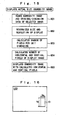
- FIG. 17(A) and (B) are flowcharts showing the third method.
- a processing of storing the size ratio is performed as a preprocessing.
- one of the commodity images stored in the storage means of the second control section 24 is immediately displayed on the LCD 14 (step SP1 of FIG. 17(A)), and then, with the use of an image scaling function, the displayed commodity image CI is manually adjusted into its actual size on the image (step SP2 of FIG. 17(A)).
- the size ratio of the commodity image CI before adjustment to that after adjustment is calculated and stored (step SP3 of FIG. 17(A)).
- a commodity image corresponding to the selected commodity is read from among the multiple commodity images stored in the storage means of the second control section 24 (step SP4 of FIG. 17(B)), and then the size ratio stored at step SP3 is read (step SP5 of FIG. 17(B)).
- the display size of the commodity image (the number of horizontal pixels ⁇ the number of vertical pixels) is calculated and determined (step SP6 of FIG. 13(B)).
- the commodity image read from the storage means of the second control section 24 is displayed in the commodity information display area B33 in the determined size (the number of horizontal pixels ⁇ the number of vertical pixels).
- the actual size commodity image RSI is displayed in the commodity information display area B33 (step SP7 of FIG. 18(B)).
- this method is similarly applicable to the case where the resolution of an actual LCD is the same as the reference resolution and its size is larger than the reference size, the case where the size of an actual LCD is the same as the reference size and its resolution is smaller than the reference resolution, and the case where both the size and the resolution of an actual LCD are different from the reference size and the reference resolution, respectively, it is not required to perform a different processing for each case unlike the first method. Furthermore, this method is not limited to a LCD whith an aspect ratio of 4:3 but is effective to the case where a LCD wich an aspect ratio of 16:9 is used.
Landscapes
- Engineering & Computer Science (AREA)
- Theoretical Computer Science (AREA)
- General Physics & Mathematics (AREA)
- Physics & Mathematics (AREA)
- General Engineering & Computer Science (AREA)
- Business, Economics & Management (AREA)
- Accounting & Taxation (AREA)
- Human Computer Interaction (AREA)
- General Business, Economics & Management (AREA)
- Strategic Management (AREA)
- Finance (AREA)
- Control Of Vending Devices And Auxiliary Devices For Vending Devices (AREA)
- Image Processing (AREA)
- User Interface Of Digital Computer (AREA)
Applications Claiming Priority (4)
| Application Number | Priority Date | Filing Date | Title |
|---|---|---|---|
| JP2004005490 | 2004-01-13 | ||
| JP2004005490 | 2004-01-13 | ||
| JP2004332911A JP2005228296A (ja) | 2004-01-13 | 2004-11-17 | 自動販売機 |
| JP2004332911 | 2004-11-17 |
Publications (2)
| Publication Number | Publication Date |
|---|---|
| EP1564694A2 true EP1564694A2 (fr) | 2005-08-17 |
| EP1564694A3 EP1564694A3 (fr) | 2006-06-21 |
Family
ID=34703348
Family Applications (1)
| Application Number | Title | Priority Date | Filing Date |
|---|---|---|---|
| EP05250118A Withdrawn EP1564694A3 (fr) | 2004-01-13 | 2005-01-12 | Machine de vente |
Country Status (3)
| Country | Link |
|---|---|
| US (1) | US20050234590A1 (fr) |
| EP (1) | EP1564694A3 (fr) |
| JP (1) | JP2005228296A (fr) |
Families Citing this family (10)
| Publication number | Priority date | Publication date | Assignee | Title |
|---|---|---|---|---|
| JP2008186198A (ja) * | 2007-01-29 | 2008-08-14 | Fuji Electric Retail Systems Co Ltd | 自動販売機 |
| DE112008002167B4 (de) * | 2007-04-26 | 2014-02-06 | Panasonic Corporation | Kühlschrank und elektrische Vorrichtung |
| US8201736B2 (en) * | 2007-08-01 | 2012-06-19 | Tuttoespresso S.R.L. | Automatic dispensing machine and method for its operation |
| JP5129707B2 (ja) * | 2008-09-24 | 2013-01-30 | 株式会社日立システムズ | 画像実寸表示システムおよび画像実寸表示方法ならびにそのためのプログラム |
| US8463430B2 (en) | 2008-10-23 | 2013-06-11 | Utique, Inc | Interactive and 3-D multi-senor touch selection interface for an automated retail store, vending machine, digital sign, or retail display |
| US9164954B2 (en) | 2012-10-08 | 2015-10-20 | The Coca-Cola Company | Vending accommodation and accessibility |
| MX2021011586A (es) | 2019-03-25 | 2021-10-13 | Pepsico Inc | Dispensador de recipientes para bebidas y metodo para dispensar recipientes para bebidas. |
| WO2020205877A1 (fr) * | 2019-04-05 | 2020-10-08 | Pepsico, Inc. | Refroidisseur pour récipients de boisson |
| US11910815B2 (en) * | 2019-12-02 | 2024-02-27 | Pepsico, Inc. | Device and method for nucleation of a supercooled beverage |
| JP2024507618A (ja) * | 2020-12-02 | 2024-02-21 | ザ プロクター アンド ギャンブル カンパニー | 物理的消費者製品を吐出するための仮想没入型及び物理的デジタルシステム及び方法 |
Family Cites Families (22)
| Publication number | Priority date | Publication date | Assignee | Title |
|---|---|---|---|---|
| US4967896A (en) * | 1985-03-04 | 1990-11-06 | Tokyo Sanyo Electric Co., Ltd. | Control arrangement for automatic vending machine |
| GB2300551A (en) * | 1995-05-03 | 1996-11-06 | Ibm | Computer workstation |
| JP3673336B2 (ja) * | 1996-09-06 | 2005-07-20 | サンデン株式会社 | 自動販売機 |
| JP3476648B2 (ja) * | 1996-11-28 | 2003-12-10 | 日本たばこ産業株式会社 | 自動販売機 |
| KR100201271B1 (ko) * | 1997-03-11 | 1999-06-15 | 최진호 | 자동판매기의 연속판매 장치 및 방법 |
| US6313851B1 (en) * | 1997-08-27 | 2001-11-06 | Microsoft Corporation | User friendly remote system interface |
| US6160553A (en) * | 1998-09-14 | 2000-12-12 | Microsoft Corporation | Methods, apparatus and data structures for providing a user interface, which exploits spatial memory in three-dimensions, to objects and in which object occlusion is avoided |
| JP2003527655A (ja) * | 1999-08-02 | 2003-09-16 | アイビューイット・ホールディングズ・インコーポレーテッド | 改良されたデジタル画像ファイルを提供するためのシステムおよび方法 |
| US6755322B1 (en) * | 2000-02-22 | 2004-06-29 | Hettie J. Herzog | Automated shopping system and apparatus |
| GB0008931D0 (en) * | 2000-04-11 | 2000-05-31 | Hewlett Packard Co | Shopping assistance method and apparatus |
| JP2002041023A (ja) * | 2000-07-06 | 2002-02-08 | Internatl Business Mach Corp <Ibm> | コンピュータシステム、表示制御装置、ディスプレイ装置、表示制御方法、記憶媒体及びプログラム伝送装置 |
| WO2002015102A1 (fr) * | 2000-08-15 | 2002-02-21 | Extreming, Inc. | Article, procede, systeme et serveur multimedia en continu virtuel permettant d'etablir un commerce electronique |
| JP2002092717A (ja) * | 2000-09-20 | 2002-03-29 | Sanyo Electric Co Ltd | 自動販売機の扉装置 |
| US7240294B2 (en) * | 2000-10-20 | 2007-07-03 | Desknet Inc. | Method of constructing a composite image |
| JP2002297971A (ja) * | 2001-01-24 | 2002-10-11 | Sony Computer Entertainment Inc | 電子商取引システム、商品適合判定装置及び方法 |
| DE10134270A1 (de) * | 2001-07-18 | 2003-02-06 | Heidenhain Gmbh Dr Johannes | Verfahren zur Erzeugung pixelorientierter Bilddateien zur Darstellung graphischer Symbole durch eine numerische Steuerung |
| JP2003162761A (ja) * | 2001-11-22 | 2003-06-06 | Sanden Corp | 自動販売機 |
| US20030146235A1 (en) * | 2002-01-28 | 2003-08-07 | Peeler Harvey S. | Drive-up vending system |
| US7289880B2 (en) * | 2002-10-04 | 2007-10-30 | Dixie-Narco, Inc. | Micro-processor programmable and selectable vending options and control |
| US6911992B2 (en) * | 2002-10-18 | 2005-06-28 | Hewlett-Packard Development Company, L.P. | Poster preparation system and method |
| US7339598B2 (en) * | 2003-07-11 | 2008-03-04 | Vistaprint Technologies Limited | System and method for automated product design |
| JP2006011584A (ja) * | 2004-06-23 | 2006-01-12 | Sanden Corp | 自動販売機 |
-
2004
- 2004-11-17 JP JP2004332911A patent/JP2005228296A/ja active Pending
-
2005
- 2005-01-12 EP EP05250118A patent/EP1564694A3/fr not_active Withdrawn
- 2005-01-13 US US11/033,866 patent/US20050234590A1/en not_active Abandoned
Non-Patent Citations (1)
| Title |
|---|
| None * |
Also Published As
| Publication number | Publication date |
|---|---|
| JP2005228296A (ja) | 2005-08-25 |
| EP1564694A3 (fr) | 2006-06-21 |
| US20050234590A1 (en) | 2005-10-20 |
Similar Documents
| Publication | Publication Date | Title |
|---|---|---|
| US8781622B2 (en) | Mobile device assisted retail system and process in a vending unit, retail display or automated retail store | |
| US20110022980A1 (en) | Virtual visual selection merchandising interface | |
| US20050155060A1 (en) | Display system for vending machine | |
| US20230022418A1 (en) | Handles and displays for product vending system | |
| JP4326348B2 (ja) | 自動販売機 | |
| US8261980B1 (en) | Automated food service and billing system and method | |
| EP1564694A2 (fr) | Machine de vente | |
| CA2833670A1 (fr) | Paradigme de "panier d'achat" destine a un flux de traitement de transactions d'un distributeur automatique a un seul ou plusieurs types de ventes | |
| EP2203880A1 (fr) | Système de restaurant multimédia, cabine et procédés associés | |
| WO2023235816A2 (fr) | Systèmes de vente sans surveillance et leurs procédés d'utilisation | |
| JP2005202683A (ja) | 自動販売機 | |
| JP3830716B2 (ja) | 自動販売装置 | |
| JP4319052B2 (ja) | 自動販売機表示システム | |
| JP2008040749A (ja) | 自動販売機 | |
| JP2005202487A (ja) | 自動販売機 | |
| JPH07191643A (ja) | 飲食店のメニュー提示方法、その装置、注文管理方法及びその装置 | |
| JP2008059092A (ja) | 自動販売機 | |
| JPH1166155A (ja) | 飲食物注文装置 | |
| JP2008059091A (ja) | 自動販売機 | |
| US20080162276A1 (en) | Interactive Terminal With Advertising Screen | |
| JP3246793U (ja) | 自動販売機 | |
| JP2022189049A (ja) | 自動販売機システム及び自動販売機 | |
| JP2003162761A (ja) | 自動販売機 | |
| KR102722377B1 (ko) | 광고 플랫폼 자판기와 그 자판기를 이용한 광고 처리 및 자동 판매 처리 방법 | |
| JP2004094183A (ja) | 画像広告システム |
Legal Events
| Date | Code | Title | Description |
|---|---|---|---|
| PUAI | Public reference made under article 153(3) epc to a published international application that has entered the european phase |
Free format text: ORIGINAL CODE: 0009012 |
|
| AK | Designated contracting states |
Kind code of ref document: A2 Designated state(s): AT BE BG CH CY CZ DE DK EE ES FI FR GB GR HU IE IS IT LI LT LU MC NL PL PT RO SE SI SK TR |
|
| AX | Request for extension of the european patent |
Extension state: AL BA HR LV MK YU |
|
| PUAL | Search report despatched |
Free format text: ORIGINAL CODE: 0009013 |
|
| AK | Designated contracting states |
Kind code of ref document: A3 Designated state(s): AT BE BG CH CY CZ DE DK EE ES FI FR GB GR HU IE IS IT LI LT LU MC NL PL PT RO SE SI SK TR |
|
| AX | Request for extension of the european patent |
Extension state: AL BA HR LV MK YU |
|
| 17P | Request for examination filed |
Effective date: 20061027 |
|
| 17Q | First examination report despatched |
Effective date: 20061128 |
|
| AKX | Designation fees paid |
Designated state(s): DE ES IT NL |
|
| STAA | Information on the status of an ep patent application or granted ep patent |
Free format text: STATUS: THE APPLICATION IS DEEMED TO BE WITHDRAWN |
|
| 18D | Application deemed to be withdrawn |
Effective date: 20080801 |