EP1564360A1 - Vorrichtung zum motorischen Öffnen und Schliessen eines Karosserieteils - Google Patents
Vorrichtung zum motorischen Öffnen und Schliessen eines Karosserieteils Download PDFInfo
- Publication number
- EP1564360A1 EP1564360A1 EP05000208A EP05000208A EP1564360A1 EP 1564360 A1 EP1564360 A1 EP 1564360A1 EP 05000208 A EP05000208 A EP 05000208A EP 05000208 A EP05000208 A EP 05000208A EP 1564360 A1 EP1564360 A1 EP 1564360A1
- Authority
- EP
- European Patent Office
- Prior art keywords
- bowden cable
- guide cylinder
- slider
- piston
- closure wall
- Prior art date
- Legal status (The legal status is an assumption and is not a legal conclusion. Google has not performed a legal analysis and makes no representation as to the accuracy of the status listed.)
- Granted
Links
- 230000006835 compression Effects 0.000 claims description 5
- 238000007906 compression Methods 0.000 claims description 5
- 238000001514 detection method Methods 0.000 claims description 4
- 238000009434 installation Methods 0.000 description 2
- 230000002441 reversible effect Effects 0.000 description 2
- 238000010276 construction Methods 0.000 description 1
- 230000001747 exhibiting effect Effects 0.000 description 1
- 238000007654 immersion Methods 0.000 description 1
Images


Classifications
-
- E—FIXED CONSTRUCTIONS
- E05—LOCKS; KEYS; WINDOW OR DOOR FITTINGS; SAFES
- E05F—DEVICES FOR MOVING WINGS INTO OPEN OR CLOSED POSITION; CHECKS FOR WINGS; WING FITTINGS NOT OTHERWISE PROVIDED FOR, CONCERNED WITH THE FUNCTIONING OF THE WING
- E05F15/00—Power-operated mechanisms for wings
- E05F15/60—Power-operated mechanisms for wings using electrical actuators
- E05F15/603—Power-operated mechanisms for wings using electrical actuators using rotary electromotors
- E05F15/611—Power-operated mechanisms for wings using electrical actuators using rotary electromotors for swinging wings
- E05F15/63—Power-operated mechanisms for wings using electrical actuators using rotary electromotors for swinging wings operated by swinging arms
-
- E—FIXED CONSTRUCTIONS
- E05—LOCKS; KEYS; WINDOW OR DOOR FITTINGS; SAFES
- E05F—DEVICES FOR MOVING WINGS INTO OPEN OR CLOSED POSITION; CHECKS FOR WINGS; WING FITTINGS NOT OTHERWISE PROVIDED FOR, CONCERNED WITH THE FUNCTIONING OF THE WING
- E05F15/00—Power-operated mechanisms for wings
- E05F15/60—Power-operated mechanisms for wings using electrical actuators
- E05F15/603—Power-operated mechanisms for wings using electrical actuators using rotary electromotors
- E05F15/611—Power-operated mechanisms for wings using electrical actuators using rotary electromotors for swinging wings
- E05F15/627—Power-operated mechanisms for wings using electrical actuators using rotary electromotors for swinging wings operated by flexible elongated pulling elements, e.g. belts, chains or cables
-
- E—FIXED CONSTRUCTIONS
- E05—LOCKS; KEYS; WINDOW OR DOOR FITTINGS; SAFES
- E05Y—INDEXING SCHEME ASSOCIATED WITH SUBCLASSES E05D AND E05F, RELATING TO CONSTRUCTION ELEMENTS, ELECTRIC CONTROL, POWER SUPPLY, POWER SIGNAL OR TRANSMISSION, USER INTERFACES, MOUNTING OR COUPLING, DETAILS, ACCESSORIES, AUXILIARY OPERATIONS NOT OTHERWISE PROVIDED FOR, APPLICATION THEREOF
- E05Y2900/00—Application of doors, windows, wings or fittings thereof
- E05Y2900/50—Application of doors, windows, wings or fittings thereof for vehicles
- E05Y2900/53—Type of wing
- E05Y2900/536—Hoods
-
- Y—GENERAL TAGGING OF NEW TECHNOLOGICAL DEVELOPMENTS; GENERAL TAGGING OF CROSS-SECTIONAL TECHNOLOGIES SPANNING OVER SEVERAL SECTIONS OF THE IPC; TECHNICAL SUBJECTS COVERED BY FORMER USPC CROSS-REFERENCE ART COLLECTIONS [XRACs] AND DIGESTS
- Y10—TECHNICAL SUBJECTS COVERED BY FORMER USPC
- Y10T—TECHNICAL SUBJECTS COVERED BY FORMER US CLASSIFICATION
- Y10T74/00—Machine element or mechanism
- Y10T74/18—Mechanical movements
- Y10T74/18568—Reciprocating or oscillating to or from alternating rotary
- Y10T74/18832—Reciprocating or oscillating to or from alternating rotary including flexible drive connector [e.g., belt, chain, strand, etc.]
-
- Y—GENERAL TAGGING OF NEW TECHNOLOGICAL DEVELOPMENTS; GENERAL TAGGING OF CROSS-SECTIONAL TECHNOLOGIES SPANNING OVER SEVERAL SECTIONS OF THE IPC; TECHNICAL SUBJECTS COVERED BY FORMER USPC CROSS-REFERENCE ART COLLECTIONS [XRACs] AND DIGESTS
- Y10—TECHNICAL SUBJECTS COVERED BY FORMER USPC
- Y10T—TECHNICAL SUBJECTS COVERED BY FORMER US CLASSIFICATION
- Y10T74/00—Machine element or mechanism
- Y10T74/20—Control lever and linkage systems
- Y10T74/20396—Hand operated
- Y10T74/20402—Flexible transmitter [e.g., Bowden cable]
- Y10T74/20462—Specific cable connector or guide
Definitions
- the invention relates to a device for motorized opening and closing a pivotable about a flap body part a motor vehicle, in particular a tailgate or a Front hood, with a guideway in which a slider slidable is guided, which has an actuating rod, with its one end attached to the slider and opposite to the slider End at a distance to the flap axis on the pivoting body part is hinged, and with a drive through which the slider reversibly slidably driven in the guideway, wherein the Drive has a first Bowden cable and a second Bowden cable, which are actuated by a drive device.
- the actuating rod with pivotally hinged to one end of the slider.
- the two Bowden cables are attached with their one ends to the slider and extend oppositely through the guideway to from the opposite ends of the guideway to the Drive device to be passed. Depending on the direction of movement is the slider is acted upon by a soul pulling one of the Bowden cables.
- This device requires a large amount of space in a motor vehicle.
- the object of the invention is therefore an apparatus of the aforementioned To create a way that with a simple construction a small installation space requires.
- the drive device a reversibly rotatable drivable cable drum, on The souls of the first and the second Bowden draw in opposite directions can be wound up or unwound.
- the two Bowden cables can each have a separate soul.
- the cable drum is preferably rotatable by electric motor, the cable drum of a reversible by reversing the direction of rotation electric motor driven can be.
- a structure with simple and therefore inexpensive components is so achieved that the guide track a guide cylinder and the slider a slidably guided in the guide cylinder piston which is a having the actuating rod forming one-sided piston rod with its one end protrudes from the guide cylinder.
- the one to the extension of the guide cylinder axial guide bore has, through which the actuating rod slidably passed is.
- the second closure wall can have an axial through-bore, through which the first Bowden cable is slidably passed.
- the opening movement may be the pivoting body part, the actuating rod be spring-loaded in the extension direction.
- the guide cylinder be enclosed with play by a helical compression spring with its one end to a support element of the guide cylinder and with its other end to a support member of the guide cylinder supported outstanding end of the actuating rod is.
- the respective position of the pivotable body part can by a position detection device, the respective axial position the actuating rod or the slider in the guideway detectable be.
- the position detection device is a Immersion pulse sensor or a linear potentiometer.
- a tailgate 1 is shown, which is about a flap axis. 2 is pivotally mounted on the body of a motor vehicle.
- the free end 4 of a piston rod 3 pivotally hinged to the tailgate 1.
- the piston rod 3 leads into a guide cylinder 5 and is there with its other end a slidably guided in the guide cylinder 5 piston 6 connected.
- the guide cylinder 5 is at its the free end 4 of the piston rod 3 opposite end to a parallel to the flap axis 2 Swivel axis 7 pivotally hinged to the body of the motor vehicle.
- the souls 9 and 10 of the two Bowden cables 8 and 11 form a closed Loop and wrap the rope drum 13.
- the one soul is wound by the same amount, as the other soul is unwound so that the two souls 9 and 10 then move in opposite directions.
- the piston rod-side end of the guide cylinder 5 is closed by a first closure wall 14 and the opposite end of the guide cylinder 5 by a second closure wall 15.
- the second closure wall 15 is a bottom of a cup-shaped guide cylinder 5, while in the embodiment of Figure 2, the second closure wall 15 is a firmly inserted into the tubular guide cylinder 5 insert part.
- the first closure wall 14 has an axial guide bore 16, through which the piston rod 3 is slidably guided.
Landscapes
- Power-Operated Mechanisms For Wings (AREA)
Abstract
Description
- Figur 1
- eine Heckklappe eines Kraftfahrzeugs mit einer Seitenansicht einer Vorrichtung zum motorischen Öffnen und Schließen der Heckklappe
- Figur 2
- die Vorrichtung zum motorischen Öffnen und Schließen nach Figur 1 im Schnitt
- Figur 3
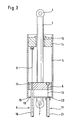
- ein zweites Ausführungsbeispiel einer Vorrichtung zum motorischen Öffnen und Schließen einer Heckklappe im Schnitt
- Figur 4
- ein drittes Ausführungsbeispiel einer Vorrichtung zum motorischen Öffnen und Schließen einer Heckklappe im Schnitt
- Figur 5
- ein viertes Ausführungsbeispiel einer Vorrichtung zum motorischen Öffnen und Schließen einer Heckklappe im Schnitt.
Bei den Ausführungsbeispielen der Figuren 3 bis 5 ist die zweite Verschlußwand 15 ein Boden eines topfartig ausgebildeten Führungszylinders 5, während bei dem Ausführungsbeispiel der Figur 2 die zweite Verschlußwand 15 ein in den rohrförmigen Führungszylinder 5 fest eingesetztes Einsatzteil ist.
Diese Ausfahrbewegung wird bei den Ausführungsbeispielen der Figuren 4 und 5 durch eine vorgespannte Schraubendruckfeder 22 unterstützt, die mit Spiel den Führungszylinder 5 umschließt und mit ihrem einen Ende an einem Abstützelement 23 des Führungszylinders 5 abgestützt ist. Das andere Ende der Schraubendruckfeder 22 ist an einem Abstützelement 24 an dem aus dem Führungszylinder 5 herausragenden Ende der Kolbenstange 3 abgestützt.
- 1
- Heckklappe
- 2
- Klappenachse
- 3
- Kolbenstange
- 4
- freies Ende
- 5
- Führungszylinder
- 6
- Kolben
- 7
- Schwenkachse
- 8
- erster Bowdenzug
- 9
- Seele
- 10
- Seele
- 11
- zweiter Bowdenzug
- 12
- Elektromotor
- 13
- Seiltrommel
- 14
- erste Verschlußwand
- 15
- zweite Verschlußwand
- 16
- Führungsbohrung
- 17
- Axialöffnung
- 18
- Hülle
- 19
- Durchführbohrung
- 20
- Durchführbohrung
- 21
- Hülle
- 22
- Schraubendruckfeder
- 23
- Abstützelement
- 24
- Abstützelement
- 25
- Sensorstange
- 26
- Sensoröffnung
Claims (15)
- Vorrichtung zum motorischen Öffnen und Schließen eines um eine Klappenachse schwenkbaren Karosserieteils eines Kraftfahrzeugs, insbesondere einer Heckklappe oder einer Fronthaube, mit einer Führungsbahn, in der ein Gleitstück verschiebbar geführt ist, das eine Betätigungsstange besitzt, die mit ihrem einen Ende an dem Gleitstück befestigt und mit ihrem dem Gleitstück entgegengesetzten Ende in einem Abstand zur Klappenachse an dem schwenkbaren Karosserieteil angelenkt ist, und mit einem Antrieb, durch den das Gleitstück in der Führungsbahn reversierbar verschiebbar antreibbar ist, wobei der Antrieb einen ersten Bowdenzug und einen zweiten Bowdenzug besitzt, die von einer Antriebsvorrichtung betätigbar sind, dadurch gekennzeichnet, daß die Führungsbahn mit ihrem einen Ende insbesondere um eine zur Klappenachse (2) parallele Schwenkachse (7) schwenkbar an der Karosserie angelenkt und die Betätigungsstange mit dem Gleitstück axial verschiebbar in der Führungsbahn geführt ist und an dem der Klappenachse (2) entgegengesetzten Ende aus der Führungsbahn herausragt, wobei der erste Bowdenzug (8) und der zweite Bowdenzug (11) parallel zueinander an dem klappenachsenseitigen Ende der Führungsbahn von der Führungsbahn weg zur Antriebsvorrichtung geführt sind, und wobei die Seele (9) des ersten Bowdenzugs (8) mit der Führungsbahn und die Seele (10) des zweiten Bowdenzugs (11) mit dem Gleitstück fest verbunden sowie die Hülle (18) des ersten Bowdenzugs (8) an dem Gleitstück und die Hülle (21) des zweiten Bowdenzugs (11) an der Führungsbahn abgestützt ist.
- Vorrichtung nach Anspruch 1, dadurch gekennzeichnet, daß die Antriebsvorrichtung eine reversierbar drehbar antreibbare Seiltrommel (13) aufweist, auf die die Seelen (9, 10) des ersten und des zweiten Bowdenzugs (8, 11) einander gegenläufig auf- bzw. abwickelbar sind.
- Vorrichtung nach Anspruch 1, dadurch gekennzeichnet, daß die Seelen (9, 10) des ersten und des zweiten Bowdenzugs (8, 11) eine geschlossene Schleife bilden.
- Vorrichtung nach einem der Ansprüche 2 und 3, dadurch gekennzeichnet, daß die Seiltrommel (13) elektromotorisch drehbar antreibbar ist.
- Vorrichtung nach Anspruch 4, dadurch gekennzeichnet, daß die Seiltrommel (13) von einem durch Umpolung drehrichtungsumkehrbaren Elektromotor (12) antreibbar ist.
- Vorrichtung nach einem der vorhergehenden Ansprüche, dadurch gekennzeichnet, daß die Führungsbahn ein Führungszylinder (5) und das Gleitstück ein in dem Führungszylinder (5) verschiebbar geführter Kolben (6) ist, der eine die Betätigungsstange bildende einseitige Kolbenstange (3) aufweist, die mit ihrem einen Ende aus dem Führungszylinder (5) herausragt.
- Vorrichtung nach Anspruch 6, dadurch gekennzeichnet, daß der Führungszylinder (5) an seinem einen Ende durch eine erste Verschlußwand (14) verschlossen ist, die eine zur Erstreckung des Führungszylinders (5) axiale Führungsbohrung (16) aufweist, durch die die Betätigungsstange verschiebbar hindurchgeführt ist.
- Vorrichtung nach einem der Ansprüche 6 und 7, dadurch gekennzeichnet, daß der Führungszylinder (5) an seinem anderen Ende durch eine zweite Verschlußwand (15) verschlossen ist.
- Vorrichtung nach einem der Ansprüche 7 und 8, dadurch gekennzeichnet, daß das eine Ende der Seele (9) des ersten Bowdenzugs (8) mit der ersten Verschlußwand (14) verbunden ist und der erste Bowdenzug (8) sich axial durch den Führungszylinder (5) erstreckt, wobei die Seele (9) des ersten Bowdenzugs (8) sich verschiebbar durch eine Axialöffnung (17) des Kolbens (6) erstreckt und das eine Ende der Hülle (18) des ersten Bowdenzugs (8) auf der der ersten Verschlußwand (14) entgegengesetzten Seite des Kolbens (6) axial abgestützt ist.
- Vorrichtung nach einem der Ansprüche 7 bis 9, dadurch gekennzeichnet, daß die zweite Verschlußwand (15) eine axiale Durchführbohrung (19) aufweist, durch die der erste Bowdenzug (18) verschiebbar hindurchgeführt ist.
- Vorrichtung nach einem der Ansprüche 6 bis 10, dadurch gekennzeichnet, daß das eine Ende der Seele (10) des zweiten Bowdenzugs (11) mit dem Kolben (6) verbunden ist und der zweite Bowdenzug (11) sich axial durch den Führungszylinder (5) erstreckt, wobei die Seele (10) des zweiten Bowdenzugs (11) sich verschiebbar durch eine Durchführbohrung (20) der zweiten Verschlußwand (15) erstreckt und das eine Ende der Hülle (21) des zweiten Bowdenzugs (11) auf der dem Kolben (6) abgewandten Seite der zweiten Verschlußwand (15) axial abgestützt ist.
- Vorrichtung nach einem der vorhergehenden Ansprüche, dadurch gekennzeichnet, daß die Betätigungsstange in Ausfahrrichtung federbeaufschlagt ist.
- Vorrichtung nach Anspruch 12, dadurch gekennzeichnet, daß der Führungszylinder (5) mit Spiel von einer Schraubendruckfeder (22) umschlossen ist, die mit ihrem einen Ende an einem Abstützelement (24) des Führungszylinders (5) und mit ihrem anderen Ende an einem Abstützelement (24) des aus dem Führungszylinder (5) herausragenden Endes der Betätigungsstange abgestützt ist.
- Vorrichtung nach einem der vorhergehenden Ansprüche, dadurch gekennzeichnet, daß durch eine Positionserfassungseinrichtung die jeweilige axiale Position der Betätigungsstange oder des Gleitstücks in der Führungsbahn erfaßbar ist.
- Vorrichtung nach Anspruch 14, dadurch gekennzeichnet, daß die Positionserfassungseinrichtung ein Tauchspulsensor oder ein Linearpotentiometer ist.
Applications Claiming Priority (2)
| Application Number | Priority Date | Filing Date | Title |
|---|---|---|---|
| DE102004007126A DE102004007126A1 (de) | 2004-02-12 | 2004-02-12 | Vorrichtung zum motorischen Öffnen und Schließen eines Karosserieteils |
| DE102004007126 | 2004-02-12 |
Publications (2)
| Publication Number | Publication Date |
|---|---|
| EP1564360A1 true EP1564360A1 (de) | 2005-08-17 |
| EP1564360B1 EP1564360B1 (de) | 2007-07-04 |
Family
ID=34684042
Family Applications (1)
| Application Number | Title | Priority Date | Filing Date |
|---|---|---|---|
| EP05000208A Expired - Lifetime EP1564360B1 (de) | 2004-02-12 | 2005-01-07 | Vorrichtung zum motorischen Öffnen und Schliessen eines Karosserieteils |
Country Status (3)
| Country | Link |
|---|---|
| US (1) | US7506556B2 (de) |
| EP (1) | EP1564360B1 (de) |
| DE (2) | DE102004007126A1 (de) |
Cited By (1)
| Publication number | Priority date | Publication date | Assignee | Title |
|---|---|---|---|---|
| WO2018060009A1 (de) * | 2016-09-28 | 2018-04-05 | Brose Fahrzeugteile Gmbh & Co. Kg, Bamberg | Antriebskinematik |
Families Citing this family (8)
| Publication number | Priority date | Publication date | Assignee | Title |
|---|---|---|---|---|
| DE102005030054B4 (de) * | 2005-06-27 | 2009-04-02 | Stabilus Gmbh | Öffnungsvorrichtung |
| DE202005021669U1 (de) * | 2005-07-08 | 2009-03-12 | Stabilus Gmbh | Vorrichtung zum motor- und kraftbetätigten Bewegen einer um eine Schwenkachse schwenkbaren Klappe eines Fahrzeugs |
| US7926863B2 (en) * | 2007-07-31 | 2011-04-19 | Dura Global Technologies, Llc | Power hinge mechanism using a push-pull cable |
| DE102007053452A1 (de) * | 2007-11-07 | 2009-05-14 | Stabilus Gmbh | Antriebseinrichtung |
| DE102008009898B4 (de) * | 2007-11-13 | 2010-07-15 | Stabilus Gmbh | Klappenöffnungs- und -schließsystem |
| TWM412127U (en) * | 2011-01-31 | 2011-09-21 | Ren-Fa Luo | Improved front and rear wheel brake control device |
| AT512156B1 (de) * | 2012-05-25 | 2013-06-15 | Blum Gmbh Julius | Anordnung zum Bewegen eines bewegbaren Möbelteils |
| JP6768401B2 (ja) * | 2016-08-05 | 2020-10-14 | 株式会社ユーシン | 車両用ドア開閉装置 |
Citations (1)
| Publication number | Priority date | Publication date | Assignee | Title |
|---|---|---|---|---|
| FR2730714A1 (fr) * | 1995-02-16 | 1996-08-23 | Renault | Verin motorise, notamment pour dispositif de commande d'ouverture et de fermeture d'un hayon de vehicule automobile |
Family Cites Families (21)
| Publication number | Priority date | Publication date | Assignee | Title |
|---|---|---|---|---|
| US2914955A (en) * | 1957-11-12 | 1959-12-01 | Univ Kingston | Synchronizing mechanism for free piston engines |
| JPS5917621A (ja) * | 1982-07-20 | 1984-01-28 | Nissan Motor Co Ltd | プツシユ・プル・ケ−ブルの伝達力取出装置 |
| DE3329543A1 (de) * | 1983-08-16 | 1985-02-28 | Geze Gmbh, 7250 Leonberg | Vorrichtung zur regelung der schliessfolge von zweifluegeligen tueren |
| US4702117A (en) * | 1986-03-31 | 1987-10-27 | Kokusan Kinzoku Kogyo Kabushiki Kaisha | Lock actuator for a pair of locks |
| US4900187A (en) * | 1987-10-23 | 1990-02-13 | Nyman Pile Driving, Inc. | Hydraulic actuator and lift apparatus |
| DE3744083A1 (de) * | 1987-12-24 | 1989-07-06 | Opel Adam Ag | Vorrichtung zum motorischen oeffnen und schliessen schwenkbarer karosserieteile von kraftfahrzeugen |
| US4851742A (en) | 1989-01-26 | 1989-07-25 | General Motors Corporation | Compartment panel control apparatus for a motor vehicle |
| US4936424A (en) * | 1989-05-09 | 1990-06-26 | Costa Vince F | Hydraulic shock absorber with pressure sensitive external valving |
| DE4124869A1 (de) | 1991-07-26 | 1993-01-28 | Bayerische Motoren Werke Ag | Vorrichtung zum motor- und kraftbetaetigten bewegen einer klappe, insbesondere einer heckklappe fuer kraftfahrzeuge |
| DE4224132C2 (de) * | 1992-07-22 | 2002-11-14 | Stabilus Gmbh | Türfeststellsystem |
| JPH0680024A (ja) * | 1992-09-01 | 1994-03-22 | Nippondenso Co Ltd | 車両用ドアの自動開閉装置 |
| DE19504301C2 (de) * | 1994-02-10 | 1997-07-24 | Honda Motor Co Ltd | System zur wahlweisen Betätigung zweier getriebener Elemente durch ein einzelnes Betätigungselement |
| FR2717215B1 (fr) * | 1994-03-08 | 1996-04-19 | Renault | Dispositif de commande motorisé d'ouverture et de fermeture d'un hayon de véhicule automobile. |
| US5588258A (en) * | 1995-03-01 | 1996-12-31 | General Motors Corporation | Power operator for pivotable vehicle closure element |
| JP3850480B2 (ja) * | 1996-01-29 | 2006-11-29 | 中央発條株式会社 | ケーブルを用いた遠隔操作装置 |
| DE19636272A1 (de) * | 1996-09-06 | 1998-03-12 | Star Gmbh | Linearführungseinrichtung |
| ES2198183B1 (es) * | 2000-03-27 | 2005-04-01 | Stabilus Gmbh | Sistema de maniobra comprendiendo un grupo de piston-cilindro combinado con un dispositivo de accionamiento. |
| US6516567B1 (en) * | 2001-01-19 | 2003-02-11 | Hi-Lex Corporation | Power actuator for lifting a vehicle lift gate |
| DE10119340A1 (de) * | 2001-04-20 | 2002-10-31 | Stabilus Gmbh | Betätigungssystem für eine Klappe o. dergleichen |
| US6883275B2 (en) * | 2002-07-29 | 2005-04-26 | Multimatic, Inc. | Method and apparatus for controlling the speed of closing of a movable element |
| DE10245458A1 (de) * | 2002-09-28 | 2004-04-08 | Stabilus Gmbh | Betätigungseinrichtung |
-
2004
- 2004-02-12 DE DE102004007126A patent/DE102004007126A1/de not_active Withdrawn
-
2005
- 2005-01-07 DE DE502005000952T patent/DE502005000952D1/de not_active Expired - Fee Related
- 2005-01-07 EP EP05000208A patent/EP1564360B1/de not_active Expired - Lifetime
- 2005-02-09 US US11/054,475 patent/US7506556B2/en not_active Expired - Fee Related
Patent Citations (1)
| Publication number | Priority date | Publication date | Assignee | Title |
|---|---|---|---|---|
| FR2730714A1 (fr) * | 1995-02-16 | 1996-08-23 | Renault | Verin motorise, notamment pour dispositif de commande d'ouverture et de fermeture d'un hayon de vehicule automobile |
Cited By (1)
| Publication number | Priority date | Publication date | Assignee | Title |
|---|---|---|---|---|
| WO2018060009A1 (de) * | 2016-09-28 | 2018-04-05 | Brose Fahrzeugteile Gmbh & Co. Kg, Bamberg | Antriebskinematik |
Also Published As
| Publication number | Publication date |
|---|---|
| DE502005000952D1 (de) | 2007-08-16 |
| US7506556B2 (en) | 2009-03-24 |
| EP1564360B1 (de) | 2007-07-04 |
| US20050179280A1 (en) | 2005-08-18 |
| DE102004007126A1 (de) | 2005-08-25 |
Similar Documents
| Publication | Publication Date | Title |
|---|---|---|
| EP1120066A2 (de) | Schliess- und/oder Einzugsvorrichtung für bewegbare Möbelteile | |
| EP2488718B1 (de) | Selbsteinzugs- und dämpfungsvorrichtung | |
| DE102004037937B4 (de) | Türschloss, insbesondere mit Panikfunktion | |
| DE29801653U1 (de) | Kraftfahrzeug mit zumindest einer Schiebetür und einem Schiebetürantrieb | |
| DE10245458A1 (de) | Betätigungseinrichtung | |
| EP1741866A2 (de) | Vorrichtung zum motor- und krafttätigen Bewegen einer um eine Schwenkachse schwenkbaren Klappe eines Fahrzeugs | |
| DE20308256U1 (de) | Möbelantrieb | |
| DE102010044327A1 (de) | Zentrierspannvorrichtung | |
| DE202010007230U1 (de) | Bidirektionale Einzugsvorrichtung für eine mittlere Schiebetür | |
| EP2730734A2 (de) | Bidirektionale Einzugsvorrichtung für eine mittlere Schiebetür | |
| EP1564360B1 (de) | Vorrichtung zum motorischen Öffnen und Schliessen eines Karosserieteils | |
| EP0911471A2 (de) | Feststeller für schwenkbar angelenkte Bauteile | |
| EP1652707B1 (de) | Gerät zum synchronen Aus- uns Einfahren von zwei Drahtabschnitten sowie ein Kraftfahrzeug mit einem solchen Gerät | |
| DE2831870A1 (de) | Universal-seilzugfensterheber | |
| DE1605975C3 (de) | Fensterheber fur in den Fensterschacht eines Kraftfahrzeuges versenkbare Schiebefenster | |
| DE10202914B4 (de) | Ausfahrbarer Ladeboden für ein Fahrzeug | |
| DE1198239B (de) | Handbetaetigter Fensterheber fuer in den Fenster-schacht eines Kraftfahrzeugs versenkbare Schiebefenster | |
| EP0716203B1 (de) | Seilantrieb, insbesondere für ein Garagentor | |
| DE602004011477T2 (de) | Sonnenschutz und öffnungsfähiges Fahrzeugdach mit einer solchen Vorrichtung | |
| DE2900907A1 (de) | Antriebvorrichtung fuer schiebetuerfluegel oder schwenkschiebetuerfluegel von fahrzeugtueren | |
| DE10123423B4 (de) | Antrieb für ein Schließelement eines Fahrzeugdaches | |
| EP1462596A2 (de) | Rasteinrichtung für ein in einer Führung verschiebliches Gleitstück | |
| DE102009060144B4 (de) | Vorrichtung zur Betätigung eines Kipptors | |
| DE19502761B4 (de) | Zweiflügelige Tür | |
| EP1353032B1 (de) | Möbeldrehtürautomatik |
Legal Events
| Date | Code | Title | Description |
|---|---|---|---|
| PUAI | Public reference made under article 153(3) epc to a published international application that has entered the european phase |
Free format text: ORIGINAL CODE: 0009012 |
|
| AK | Designated contracting states |
Kind code of ref document: A1 Designated state(s): AT BE BG CH CY CZ DE DK EE ES FI FR GB GR HU IE IS IT LI LT LU MC NL PL PT RO SE SI SK TR |
|
| AX | Request for extension of the european patent |
Extension state: AL BA HR LV MK YU |
|
| 17P | Request for examination filed |
Effective date: 20050715 |
|
| AKX | Designation fees paid |
Designated state(s): DE ES FR GB IT |
|
| GRAP | Despatch of communication of intention to grant a patent |
Free format text: ORIGINAL CODE: EPIDOSNIGR1 |
|
| GRAS | Grant fee paid |
Free format text: ORIGINAL CODE: EPIDOSNIGR3 |
|
| GRAA | (expected) grant |
Free format text: ORIGINAL CODE: 0009210 |
|
| AK | Designated contracting states |
Kind code of ref document: B1 Designated state(s): DE ES FR GB IT |
|
| REG | Reference to a national code |
Ref country code: GB Ref legal event code: FG4D Free format text: NOT ENGLISH |
|
| REF | Corresponds to: |
Ref document number: 502005000952 Country of ref document: DE Date of ref document: 20070816 Kind code of ref document: P |
|
| ET | Fr: translation filed | ||
| GBV | Gb: ep patent (uk) treated as always having been void in accordance with gb section 77(7)/1977 [no translation filed] |
Effective date: 20070704 |
|
| PG25 | Lapsed in a contracting state [announced via postgrant information from national office to epo] |
Ref country code: ES Free format text: LAPSE BECAUSE OF FAILURE TO SUBMIT A TRANSLATION OF THE DESCRIPTION OR TO PAY THE FEE WITHIN THE PRESCRIBED TIME-LIMIT Effective date: 20071015 |
|
| PLBE | No opposition filed within time limit |
Free format text: ORIGINAL CODE: 0009261 |
|
| STAA | Information on the status of an ep patent application or granted ep patent |
Free format text: STATUS: NO OPPOSITION FILED WITHIN TIME LIMIT |
|
| PG25 | Lapsed in a contracting state [announced via postgrant information from national office to epo] |
Ref country code: GB Free format text: LAPSE BECAUSE OF FAILURE TO SUBMIT A TRANSLATION OF THE DESCRIPTION OR TO PAY THE FEE WITHIN THE PRESCRIBED TIME-LIMIT Effective date: 20070704 |
|
| 26N | No opposition filed |
Effective date: 20080407 |
|
| REG | Reference to a national code |
Ref country code: FR Ref legal event code: ST Effective date: 20081029 |
|
| PG25 | Lapsed in a contracting state [announced via postgrant information from national office to epo] |
Ref country code: FR Free format text: LAPSE BECAUSE OF NON-PAYMENT OF DUE FEES Effective date: 20080131 |
|
| PGFP | Annual fee paid to national office [announced via postgrant information from national office to epo] |
Ref country code: DE Payment date: 20090131 Year of fee payment: 5 |
|
| PG25 | Lapsed in a contracting state [announced via postgrant information from national office to epo] |
Ref country code: DE Free format text: LAPSE BECAUSE OF NON-PAYMENT OF DUE FEES Effective date: 20100803 |
|
| PG25 | Lapsed in a contracting state [announced via postgrant information from national office to epo] |
Ref country code: IT Free format text: LAPSE BECAUSE OF NON-PAYMENT OF DUE FEES Effective date: 20080131 |
|
| P01 | Opt-out of the competence of the unified patent court (upc) registered |
Effective date: 20230516 |