EP2488718B1 - Selbsteinzugs- und dämpfungsvorrichtung - Google Patents
Selbsteinzugs- und dämpfungsvorrichtung Download PDFInfo
- Publication number
- EP2488718B1 EP2488718B1 EP10771689.6A EP10771689A EP2488718B1 EP 2488718 B1 EP2488718 B1 EP 2488718B1 EP 10771689 A EP10771689 A EP 10771689A EP 2488718 B1 EP2488718 B1 EP 2488718B1
- Authority
- EP
- European Patent Office
- Prior art keywords
- damper
- damping device
- driver
- spring element
- bar linkage
- Prior art date
- Legal status (The legal status is an assumption and is not a legal conclusion. Google has not performed a legal analysis and makes no representation as to the accuracy of the status listed.)
- Not-in-force
Links
Images


Classifications
-
- E—FIXED CONSTRUCTIONS
- E05—LOCKS; KEYS; WINDOW OR DOOR FITTINGS; SAFES
- E05F—DEVICES FOR MOVING WINGS INTO OPEN OR CLOSED POSITION; CHECKS FOR WINGS; WING FITTINGS NOT OTHERWISE PROVIDED FOR, CONCERNED WITH THE FUNCTIONING OF THE WING
- E05F5/00—Braking devices, e.g. checks; Stops; Buffers
- E05F5/02—Braking devices, e.g. checks; Stops; Buffers specially for preventing the slamming of swinging wings during final closing movement, e.g. jamb stops
- E05F5/027—Braking devices, e.g. checks; Stops; Buffers specially for preventing the slamming of swinging wings during final closing movement, e.g. jamb stops with closing action
-
- E—FIXED CONSTRUCTIONS
- E05—LOCKS; KEYS; WINDOW OR DOOR FITTINGS; SAFES
- E05F—DEVICES FOR MOVING WINGS INTO OPEN OR CLOSED POSITION; CHECKS FOR WINGS; WING FITTINGS NOT OTHERWISE PROVIDED FOR, CONCERNED WITH THE FUNCTIONING OF THE WING
- E05F1/00—Closers or openers for wings, not otherwise provided for in this subclass
- E05F1/08—Closers or openers for wings, not otherwise provided for in this subclass spring-actuated, e.g. for horizontally sliding wings
- E05F1/16—Closers or openers for wings, not otherwise provided for in this subclass spring-actuated, e.g. for horizontally sliding wings for sliding wings
-
- E—FIXED CONSTRUCTIONS
- E05—LOCKS; KEYS; WINDOW OR DOOR FITTINGS; SAFES
- E05Y—INDEXING SCHEME RELATING TO HINGES OR OTHER SUSPENSION DEVICES FOR DOORS, WINDOWS OR WINGS AND DEVICES FOR MOVING WINGS INTO OPEN OR CLOSED POSITION, CHECKS FOR WINGS AND WING FITTINGS NOT OTHERWISE PROVIDED FOR, CONCERNED WITH THE FUNCTIONING OF THE WING
- E05Y2201/00—Constructional elements; Accessories therefore
- E05Y2201/40—Motors; Magnets; Springs; Weights; Accessories therefore
- E05Y2201/47—Springs; Spring tensioners
- E05Y2201/488—Traction springs
-
- E—FIXED CONSTRUCTIONS
- E05—LOCKS; KEYS; WINDOW OR DOOR FITTINGS; SAFES
- E05Y—INDEXING SCHEME RELATING TO HINGES OR OTHER SUSPENSION DEVICES FOR DOORS, WINDOWS OR WINGS AND DEVICES FOR MOVING WINGS INTO OPEN OR CLOSED POSITION, CHECKS FOR WINGS AND WING FITTINGS NOT OTHERWISE PROVIDED FOR, CONCERNED WITH THE FUNCTIONING OF THE WING
- E05Y2900/00—Application of doors, windows, wings or fittings thereof
- E05Y2900/20—Application of doors, windows, wings or fittings thereof for furnitures, e.g. cabinets
Definitions
- the present invention relates to a Disposable furniture parts according to the preamble of claim 1.
- Object of the present invention is to provide adicauchs- and damping device for movable furniture parts, in which a self-closing and damping of the movement of the movable furniture part in the direction of movement of the furniture part are made possible.
- the driver which can be coupled with the movable furniture part, the damper, with the movement of the driver at least is braked in one direction and a spring element, by means of which a movement of the driver is accelerated from a first position to a second position, coupled via a straight guide of the driver causing four-bar linkage together.
- the four-bar linkage has two with a respective end to a furniture body rotatably fixable rockers and rotatably fixed to the other ends of the rocker coupling.
- the spring element is coupled to a first coupling point formed on the articulation point of the four-bar linkage, which undergoes a curve at a the spring element on or relaxing movement of the four-bar linkage.
- the damper is coupled to the four-bar linkage such that the effective direction of the damper counteracts the direction of action of the spring element, wherein the damper is coupled to a second provided on the coupling or the rocker articulation point.
- the damper is designed as a linear damper.
- a suitable choice of the attachment points of spring element and damper is on the one hand ensures that the direction of action of the spring element counteracts the direction of action of the damper, on the other hand, so the force-displacement curve can be adjusted as needed.
- the damper is designed as a rotary damper, in particular as an eddy current brake. This is the braking effect the damper to a fluid damper largely independent of temperature influences. Furthermore, an eddy current brake can be very compact
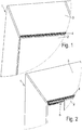
- the Figures 1 and 2 show a furniture body 1 with a, here designed as a sliding door movable furniture part 2.
- the movable furniture part 2 is provided on its the furniture body 1 side facing at least one fitting 12 (shown in FIG FIG. 5 ), on which a roller 11 is mounted, which is mounted in a mounted on a ceiling plate 3 of the furniture body guide rail 4 in a raceway 9, 10 of the guide rail 4 slidably.
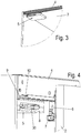
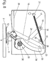
- FIG. 1 is the movable furniture part 2 in a closed position, in FIG. 2 in a partially open position, in which a variant of the Diseinzugs- and damping device 5 can be seen, which, as in the detailed representation in FIG. 3 shown, preferably fixed to the ceiling plate 3 of the furniture body 1.
- the Disclosed- and damping device 5 a housing 8, from which a driver 30 protrudes toward the movable furniture part 2 out, which is shaped so that it is fixed to the movable furniture part 2 activator 6 during movement of the movable furniture part 2 receives from a partially open position to a closed position and moves together with the movable furniture part 2 in a closed position.
- the activator 6 is preferably designed as a cylindrical rod which is mounted on a mounting platform 7, wherein the mounting platform 7 is in turn mounted on the fitting 12 on the movable furniture part 2.
- the driver 30 has a movable furniture part 2 toward approximately U-shaped opening 31 in which the activator 6 can be accommodated and the driver 30 so holds the activator 6 in the direction of movement of the movable furniture part 2.
- a tongue 32 for easier recording of the activator 6 is formed at one end of the U-shaped opening 31 of the driver 30, a tongue 32 to which the activator 6 abuts when entering the U-shaped opening 31.
- the driver 30 is coupled to a housed in the housing 8 of Dieinzugs- and damping device 5 four-bar linkage 13.
- the four-bar linkage 13 consists of two with a respective end to the furniture body 1 rotatably fixed wings 14, 15 and at the other ends of the rockers 14, 15 rotatably fixed coupling 16. At the free end of the coupling 16 of the driver 30 is coupled.
- the four-bar linkage 13 is further coupled to a movement of the driver 30 from a first position to a second position in a direction accelerating spring element 17 and a damper 18, by means of which a movement of the driver 30 in the direction in which the spring force of Spring element 17 acts, is braked.
- the attachment points 19, 20, on which the wings 14,15 are fixed to the furniture body 1 and the coupling joints 23, 24 of the wings 14, 15 with the coupling 16 are designed so that the free end of the coupling 16, on which the driver 30 is coupled, a straight guide of the driver 30 along a rectilinear portion of a cam guide 28 acts.
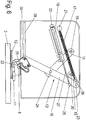
- FIG. 5 shows the four-bar linkage 13 in a position in which the driver 30 is in a closed position
- FIG. 6 shows the four-bar linkage 13 in a position in which the driver 30 is in an open position in which the driver 30 is retracted into a curve piece 29 of the cam guide 28 and thereby the open end of the U-shaped opening 31 of the driver by an angle in Opening direction of the movable furniture part 2 is twisted.
- the rocker 15 is in dead center by the action line of the spring element 17 passes through the attachment point 20 of the rocker 15. This results in a restoring torque-free state, which can be used for latching the system, since the four-bar linkage 13 does not leave the reached position without external excitation.
- the damper 18 is designed as a linear damper.
- the rotatably mounted at one end to an attachment point 22 on the furniture body 1 damper 18 is coupled here at a pivot point 25 on the coupling 16, but may, for example, on the attachment point 22 of the damper 18 closer rocker 14.
- Trained as a linear damper damper 18 is formed here, for example, as a known from the prior art damper with a housing from which a damping ram 27 protrudes, which is preferably fixed with its pivot point 25 to the coupling 16 rotatable.
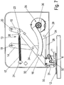
- the damper 35 is designed as a rotary damper, preferably as an eddy-current brake, as shown in FIGS FIGS. 7 and 8th is shown.
- the damping force of Dieinzugs- and damping device 5 and braking force of the eddy current brake 35 can be adjusted, for example, via the introduction of a different number of permanent magnets in a simple manner.
- a rack 33 is fixed to the rocker 14 of the four-bar mechanism 13, which is preferably shaped like a circle-shaped and is provided on its outside with teeth 34 which mesh with a ring gear 36 of the damper 35.
- the rack 33 is in this embodiment rigidly connected to the rocker 14. It is also conceivable, however, a one-piece design of rocker 14 and rack 33rd
- FIGS. 9 and 10 again show the embodiments of Diseinzugs- and damping device 5 in an exploded view, wherein FIG. 9 the embodiment with a trained as a linear damper damper 18 and FIG. 10 a variant with a designed as a rotary damper damper 35th
- FIGS. 11 and 12 is shown a comparison of a force-displacement diagram, wherein the FIG. 11 shows the force-displacement diagram of a self-closing and damping device according to the prior art, while the FIG. 12 a force-displacement diagram of a Deinyaks- and damping device according to the present invention shows.
- an increasing force must be applied during an opening operation of a movable furniture part with increasing distance traveled by the driver in order to counteract the spring force of the spring element 17.
- the spring element 17 is deflected by a large distance.
- the application of the Diseinzugs- and damping device according to the present invention is not limited to the use of a designed as a sliding door movable furniture part, but can for example be used in push elements or the like.
- a furniture equipped with such a Aseinzugs- and damping device the user is allowed to move a movable furniture part 2 of the furniture with little effort.
Description
- Die vorliegende Erfindung betrifft eine Selbsteinzugs- und Dämpfungsvorrichtung für bewegbare Möbelteile gemäß dem Oberbegriff des Anspruchs 1.
- Aus der
DE 20 2004 018 629 U1 ist eine Selbsteinzugs- und Dämpfungsvorrichtung für bewegbare Möbelteile bekannt, bei der die Dämpfungseinrichtung und/oder der Selbsteinzugsbeschlag beweglich gelagert ist bzw. sind, so dass sich ein Winkel zwischen der Wirkrichtung des Selbsteinzugsbeschlages und der Wirkrichtung der Dämpfungseinrichtung mit zunehmender Annäherung des Möbelelementes an seine Schließstellung vergrößert. Die Dämpfungskraft der Dämpfungseinrichtung wird dabei bedarfsgerecht angepasst, indem sich die Hebelverhältnisse der einzelnen Elemente zueinander verändern. Die Einzugsvorrichtung wirkt hier derart, dass zur Verschiebung des als Schiebetür ausgebildeten beweglichen Möbelteils diese zunächst quer zur späteren Bewegungsrichtung aus einer gemeinsamen Ebene mit einer weiteren Schiebetür herausgeführt werden muss, um anschließend parallel zur Ebene der anderen Schiebetür verschoben werden zu können. - Gängige Selbsteinzugs- und Dämpfungsvorrichtungen aus dem Stand der Technik, beispielsweise der
DE20 2008 016 985 U1 , bei der ein Dämpfer und eine eine Feder direkt mit einem Mitnehmer verbunden sind, sind zur Selbsthaltung des Systems auf die sogenannte "Krückstockkurve" angewiesen. Auf dieses zusätzliche Element kann bei der erfindungsgemäßen Vorrichtung verzichtet werden, indem ein rückstellmomentfreier Zustand erreicht wird. - Aufgabe der vorliegenden Erfindung ist es, eine Selbsteinzugs- und Dämpfungsvorrichtung für bewegbare Möbelteile bereitzustellen, bei der ein Selbsteinzug sowie eine Dämpfung der Bewegung des beweglichen Möbelteils in Bewegungsrichtung des Möbelteils ermöglicht sind.
- Diese Aufgabe wird durch eine Selbsteinzugs- und Dämpfungsvorrichtung für bewegbare Möbelteile mit den Merkmalen des Anspruchs 1 gelöst.
- Erfindungsgemäß sind der Mitnehmer, der mit dem bewegbaren Möbelteil koppelbar ist, der Dämpfer, mit dem eine Bewegung des Mitnehmers zumindest in eine Richtung gebremst wird sowie ein Federelement, mittels dem eine Bewegung des Mitnehmers von einer ersten Stellung in eine zweite Stellung beschleunigt wird, über ein eine Geradführung des Mitnehmers bewirkendes Viergelenkgetriebe miteinander gekoppelt.
- Das Viergelenkgetriebe weist zwei mit einem jeweiligen Ende an einem Möbelkorpus drehbar fixierbare Schwingen und eine an den jeweils anderen Enden der Schwingen drehbar fixierte Koppel auf.
- Das Federelement ist an einem ersten an der Koppel ausgebildeten Anlenkpunkt an das Viergelenkgetriebe gekoppelt, der bei einer das Federelement an- bzw. entspannenden Bewegung des Viergelenkgetriebes eine Kurve durchläuft.
- Der Dämpfer ist dabei derart an das Viergelenkgetriebe gekoppelt, dass die Wirkrichtung des Dämpfers der Wirkrichtung des Federelementes entgegenwirkt,
wobei der Dämpfer an einem zweiten auf der Koppel oder der Schwinge vorgesehenen Anlenkpunkt angekoppelt ist. - Durch den Einsatz eines solchen Viergelenkgetriebes ist dem Benutzer die Öffnung eines solchen beweglichen Möbelteiles, beispielsweise einer Schiebetür und auch eines Klappenbeschlages, erheblich erleichtert. Durch die kinematischen Hebelverhältnisse sowie die Federanlenkung des Federelements wird die für den Selbsteinzug verantwortliche Feder nur leicht gespannt und dadurch die für den Öffnungsvorgang notwendige Federspannkraft deutlich herabgesetzt. Des Weiteren wird durch den Einsatz von Drehgelenken anstatt von Linearführungen die Systemreibung reduziert.
- Durch eine geeignete Wahl der Befestigungspunkte des Federelementes innerhalb des Viergelenkgetriebes gerät eine Schwinge in Totpunktlage, indem die Wirklinie des Federelementes durch den Befestigungspunkt der Schwinge geht. Daraus resultiert ein rückstellmomentfreier Zustand, der zur Selbsthaltung des Systems genutzt werden kann, da das Viergelenkgetriebe die erreichte Stellung ohne äußere Anregung nicht verlässt.
- Ein weiterer Vorteil der erfindungsgemäßen Lösung besteht in dem konstruktiv einfachen Aufbau der Selbsteinzugs- und Dämpfungsvorrichtung
- Vorteilhafte Ausgestaltungen der Erfindung sind Gegenstand der Unteransprüche.
- Gemäß einer Ausführungsvariante ist der Dämpfer als Lineardämpfer ausgebildet. Durch geeignete Wahl der Befestigungspunkte von Federelement und Dämpfer ist zum einen gewährleistet, dass die Wirkrichtung des Federelementes der Wirkrichtung des Dämpfers entgegenwirkt, zum anderen lässt sich so der Kraft-Weg-Verlauf bedarfsweise anpassen.
- In einer alternativen Ausführungsvariante ist der Dämpfer als Rotationsdämpfer, insbesondere als Wirbelstrombremse ausgebildet. Dadurch ist die Bremswirkung
des Dämpfers gegenüber einem Fluiddämpfer weitgehend unabhängig von Temperatureinflüssen. Des Weiteren kann eine Wirbelstrombremse sehr kompakt - aufgebaut sein, was insbesondere vorteilhaft ist bei geringem zur Verfügung stehenden Bauraum.
- Nachfolgend wird die Erfindung anhand von Ausführungsbeispielen mit Bezug auf die beigefügten Zeichnungen näher erläutert. Es zeigen:
- Figur 1
- eine schematische perspektivische Ansicht eines Möbelkorpus mit daran angeordnetem beweglichen Möbelteil im geschlossenen Zustand,
- Figur 2
- eine schematische perspektivische Ansicht des Möbels aus Figur 1 im teilweise geöffneten Zustand,
- Figur 3
- eine schematische perspektivische Detailansicht des Möbels aus
Figur 2 mit daran angebrachter Ausführungsvariante einer erfindungsgemäßen Selbsteinzugs- und Dämpfungsvorrichtung, - Figur 4
- eine schematische perspektivische Detailansicht der Einbausituation der Selbsteinzugs- und Dämpfungsvorrichtung,
- Figur 5
- eine Draufsicht auf eine Ausführungsvariante der Selbsteinzugsund Dämpfungsvorrichtung und mit dieser im Eingriff stehendem beweglichen Möbelteil in der Schließstellung,
- Figur 6
- eine der
Figur 5 entsprechende Ansicht mit bewegbarem Möbelteil in der teilgeöffneten Stellung, - Figuren 7 und 8
- den
Figuren 5 und6 entsprechende Draufsichten auf eine Ausführungsvariante der Selbsteinzugs- und Dämpfungsvorrichtung mit als Rotationsdämpfer ausgebildetem Dämpfer, - Figur 9
- eine schematische perspektivische Explosionsansicht der Selbsteinzugs- und Dämpfungsvorrichtung mit als Lineardämpfer ausgebildetem Dämpfer,
- Figur 10
- eine schematische perspektivische Explosionsansicht einer Ausführungsvariante der Selbsteinzugs- und Dämpfungsvorrichtung mit als Rotationsdämpfer ausgebildetem Dämpfer,
- Figur 11
- ein typisches Kraft-Weg-Diagramm einer linear geführten, aus dem Stand der Technik bekannten Selbsteinzugs- und Dämpfungsvorrichtung und
- Figur 12
- ein Kraft-Weg-Diagramm einer Ausführungsvariante einer erfindungsgemäßen Selbsteinzugs- und Dämpfungsvorrichtung.
- Die
Figuren 1 und 2 zeigen einen Möbelkorpus 1 mit einem, hier als Schiebetür ausgebildeten beweglichen Möbelteil 2. Das bewegliche Möbelteil 2 ist auf seiner dem Möbelkorpus 1 zugewandten Seite mit mindestens einem Beschlag 12 versehen (gezeigt inFigur 5 ), an dem eine Rolle 11 montiert ist, die in einer an einer Deckenplatte 3 des Möbelkorpus montierten Führungsschiene 4 in einer Laufbahn 9, 10 der Führungsschiene 4 verschiebbar gelagert ist. InFigur 1 befindet sich das bewegliche Möbelteil 2 in einer Schließstellung, inFigur 2 in einer teilgeöffneten Position, bei der eine Ausführungsvariante der Selbsteinzugs- und Dämpfungsvorrichtung 5 zu sehen ist, die, wie in der Detaildarstellung inFigur 3 gezeigt, vorzugsweise an der Deckenplatte 3 des Möbelkorpus 1 festgelegt ist. - Wie die Darstellung in
Figur 4 zeigt, weist die Selbsteinzugs- und Dämpfungsvorrichtung 5 ein Gehäuse 8 auf, aus dem ein Mitnehmer 30 in Richtung zum beweglichen Möbelteil 2 hin herausragt, der so geformt ist, dass er einen an dem beweglichen Möbelteil 2 festgelegten Aktivator 6 während einer Bewegung des beweglichen Möbelteils 2 von einer teilweise geöffneten Stellung in eine Schließstellung aufnimmt und sich zusammen mit dem beweglichen Möbelteil 2 in eine Schließstellung bewegt. Der Aktivator 6 ist dabei vorzugsweise als zylinderförmiger Stab ausgebildet, der auf einer Montageplattform 7 befestigt ist, wobei die Montageplattform 7 ihrerseits an dem Beschlag 12 an dem beweglichen Möbelteil 2 montiert ist. - Wie in
Figur 5 zu erkennen ist, weist der Mitnehmer 30 eine zum beweglichen Möbelteil 2 hin etwa U-förmige Öffnung 31 auf, in der der Aktivator 6 aufgenommen werden kann und der Mitnehmer 30 so den Aktivator 6 in Bewegungsrichtung des beweglichen Möbelteils 2 festhält. Zur erleichterten Aufnahme des Aktivators 6 ist an einem Ende der U-förmigen Öffnung 31 des Mitnehmers 30 eine Zunge 32 ausgebildet, an die der Aktivator 6 beim Einlaufen in die U-förmige Öffnung 31 anstößt. - Wie in
Figur 5 des Weiteren zu erkennen ist, ist der Mitnehmer 30 an ein in dem Gehäuse 8 der Selbsteinzugs- und Dämpfungsvorrichtung 5 untergebrachtes Viergelenkgetriebe 13 angekoppelt. Das Viergelenkgetriebe 13 besteht aus zwei mit einem jeweiligen Ende an dem Möbelkorpus 1 drehbar fixierbaren Schwingen 14, 15 und einer an den jeweils anderen Enden der Schwingen 14, 15 drehbar fixierten Koppel 16. An dem freien Ende der Koppel 16 ist der Mitnehmer 30 angekoppelt. - Das Viergelenkgetriebe 13 ist des Weiteren mit einem eine Bewegung des Mitnehmers 30 von einer ersten Stellung in eine zweite Stellung in einer Richtung beschleunigendem Federelement 17 sowie mit einem Dämpfer 18 gekoppelt, mittels dem eine Bewegung des Mitnehmers 30 in die Richtung in die auch die Federkraft des Federelements 17 wirkt, gebremst wird. Die Befestigungspunkte 19, 20, an denen die Schwingen 14,15 an dem Möbelkorpus 1 festgelegt sind und die Koppelgelenke 23, 24 der Schwingen 14, 15 mit der Koppel 16 sind so ausgelegt, dass das freie Ende der Koppel 16, an dem der Mitnehmer 30 angekoppelt ist, eine Geradführung des Mitnehmers 30 entlang eines geradlinigen Anteils einer Kurvenführung 28 wirkt.
- Die
Figur 5 zeigt das Viergelenkgetriebe 13 in einer Position, bei der sich der Mitnehmer 30 in einer Schließstellung befindet, dieFigur 6 zeigt das Viergelenkgetriebe 13 in einer Position, in der der Mitnehmer 30 sich in einer Öffnungsstellung befindet, bei der der Mitnehmer 30 in ein Kurvenstück 29 der Kurvenführung 28 eingefahren ist und dadurch das offene Ende der U-förmigen Öffnung 31 des Mitnehmers um einen Winkel in Öffnungsrichtung des beweglichen Möbelteils 2 verdreht ist. - Wie des Weiteren in den
Figuren 5 und6 zu erkennen ist, ist das mit einem Ende an einem Befestigungspunkt 21 an dem Möbelkorpus drehbar befestigte Federelement 17 an einem ersten Anlenkpunkt 26 an das Viergelenkgetriebe 13 gekoppelt, der bei einer das Federelement 17 an- bzw. entspannenden Bewegung des Viergelenkgetriebes 13 eine Kurve durchläuft. Dadurch ist ermöglicht, dass das bevorzugt als Zugfeder ausgebildete Federelement 17 während eines Öffnungsvorgangs des beweglichen Möbelteils 2 nicht um die gleiche Strecke gedehnt werden muss, die der Mitnehmer 30 beim Verfahren in die Öffnungsposition in der Kurvenführung 28 zurücklegt. Dieser erste Anlenkpunkt 26 ist an der Koppel 16 ausgebildet. - Durch eine geeignete Wahl der Befestigungspunkte des Federelementes 17 innerhalb des Viergelenkgetriebes 13 gerät die Schwinge 15 in Totpunktlage, indem die Wirklinie des Federelementes 17 durch den Befestigungspunkt 20 der Schwinge 15 geht. Daraus resultiert ein rückstellmomentfreier Zustand, der zur Selbsthaltung des Systems genutzt werden kann, da das Viergelenkgetriebe 13 die erreichte Stellung ohne äußere Anregung nicht verlässt.
- Bei der in den
Figuren 5 und6 gezeigten ersten Ausführungsvariante der Selbsteinzugs- und Dämpfungsvorrichtung 5 ist der Dämpfer 18 als Lineardämpfer ausgebildet. Der mit einem Ende an einem Befestigungspunkt 22 an dem Möbelkorpus 1 drehbar befestigte Dämpfer 18 ist hier an einem Anlenkpunkt 25 auf der Koppel 16 angekoppelt, kann aber beispielsweise auch auf der dem Befestigungspunkt 22 des Dämpfers 18 näheren Schwinge 14 liegen. Der als Lineardämpfer ausgebildete Dämpfer 18 ist hier beispielsweise als ein aus dem Stand der Technik bekannter Dämpfer mit einem Gehäuse ausgebildet, aus dem ein Dämpfungsstößel 27 herausragt, der mit seinem Anlenkpunkt 25 bevorzugt an der Koppel 16 drehbar festgelegt ist. - Gemäß einer weiteren Ausführungsvariante der Selbsteinzugs- und Dämpfungsvorrichtung 5 ist der Dämpfer 35 als Rotationsdämpfer, bevorzugt als Wirbelstrombremse, ausgebildet, wie es in den
Figuren 7 und8 gezeigt ist. Bei einer derart ausgebildeten Selbsteinzugs- und Dämpfungsvorrichtung 5 kann die Dämpfungskraft der Selbsteinzugs- und Dämpfungsvorrichtung 5 bzw. Bremskraft der Wirbelstrombremse 35 beispielsweise über die Einbringung einer unterschiedlichen Anzahl von Permanentmagneten in einfacher Weise eingestellt werden. - Zur Kopplung des Dämpfers 35 ist an der Schwinge 14 des Viergelenkgetriebes 13 eine Zahnstange 33 befestigt, die bevorzugt kreisausschnittförmig geformt ist und an ihrer Außenseite mit Zähnen 34 versehen ist, die mit einem Zahnkranz 36 des Dämpfers 35 kämmen. Die Zahnstange 33 ist in dieser Ausführungsvariante starr mit der Schwinge 14 verbunden. Denkbar ist aber auch eine einstückige Ausführung von Schwinge 14 und Zahnstange 33.
- Die
Figuren 9 und 10 zeigen nochmals die Ausführungsvarianten der Selbsteinzugs- und Dämpfungsvorrichtung 5 in einer Explosionsdarstellung, wobeiFigur 9 die Ausführungsvariante mit einem als Lineardämpfer ausgebildeten Dämpfer 18 zeigt undFigur 10 eine Ausführungsvariante mit einem als Rotationsdämpfer ausgebildeten Dämpfer 35. - In den
Figuren 11 und 12 ist eine Gegenüberstellung eines Kraft-Weg-Diagramms gezeigt, wobei dieFigur 11 das Kraft-Weg-Diagramm einer Selbsteinzugs- und Dämpfungsvorrichtung nach dem Stand der Technik zeigt, während dieFigur 12 ein Kraft-Weg-Diagramm einer Selbsteinzugs- und Dämpfungsvorrichtung gemäß der vorliegenden Erfindung zeigt. Wie leicht zu erkennen ist, muss während eines Öffnungsvorgangs eines beweglichen Möbelteils mit zunehmender zurückgelegter Wegstrecke des Mitnehmers eine immer größere Kraft aufgebracht werden, um der Federkraft des Federelements 17 entgegenzuwirken. Bei den Selbsteinzugs- und Dämpfungsvorrichtungen gemäß dem Stand der Technik wird das Federelement 17 um eine große Wegstrecke ausgelenkt. Bei der Selbsteinzugsund Dämpfungsvorrichtung gemäß der vorliegenden Erfindung muss anfänglich etwa die gleiche Kraft aufgebracht werden, welche sich jedoch mit fortschreitender Wegstrecke verringert, da die Feder aufgrund der durch das Viergelenkgetriebe bedingten Bewegung während des Öffnungsvorgangs des beweglichen Möbelteils 2 angelenkt wird und dadurch nur geringfügig ausgezogen wird. Durch die Anlenkung des Federelementes 17 an das Viergelenkgetriebe 13 ändert sich die Wirkrichtung des Federelementes 17 zu der Schwinge 15 derart, dass das in Schließrichtung wirkende Rückstellmoment auf die Schwinge 15 bei maximal gespanntem Federelement 17 am geringsten ist. - Die Anwendung der Selbsteinzugs- und Dämpfungsvorrichtung gemäß der vorliegenden Erfindung ist nicht auf den Einsatz für ein als Schiebetür ausgebildetes bewegliches Möbelteil begrenzt, sondern kann beispielsweise auch bei Schubelementen oder dergleichen eingesetzt werden. Bei einem mit einer solchen Selbsteinzugs- und Dämpfungsvorrichtung ausgestattetem Möbel ist es dem Benutzer ermöglicht, ein bewegliches Möbelteil 2 des Möbels mit geringem Kraftaufwand zu bewegen.
-
- Möbelkorpus
- 1
- Möbelteil
- 2
- Deckenplatte
- 3
- Führungsschiene
- 4
- Selbsteinzugs- und Dämpfungsvorrichtung
- 5
- Aktivator
- 6
- Montageplattform
- 7
- Gehäuse
- 8
- Laufbahn
- 9
- Laufbahn
- 10
- Rolle
- 11
- Beschlag
- 12
- Viergelenkgetriebe
- 13
- Schwinge
- 14
- Schwinge
- 15
- Koppel
- 16
- Federelement
- 17
- Dämpfer
- 18
- Befestigungspunkt
- 19
- Befestigungspunkt
- 20
- Befestigungspunkt
- 21
- Befestigungspunkt
- 22
- Koppelgelenk
- 23
- Koppelgelenk
- 24
- Anlenkpunkt
- 25
- Anlenkpunkt
- 26
- Dämpfungsstößel
- 27
- Kurvenführung
- 28
- Kurvenstück
- 29
- Mitnehmer
- 30
- U-förmige Öffnung
- 31
- Zunge
- 32
- Zahnstange
- 33
- Zähne
- 34
- Dämpfer
- 35
- Zahnkranz
- 36
- Kraft
- F1, F2
Claims (8)
- Selbsteinzugs- und Dämpfungsvorrichtung (5) für bewegbare Möbelteile (2), aufweisend- einen Mitnehmer (30), der mit einem bewegbaren Möbelteil (2) koppelbar ist,- einen Dämpfer (18, 35), mittels dem eine Bewegung des Mitnehmers (30) zumindest in eine Richtung gebremst wird,- ein Federelement (17), mittels dem eine Bewegung des Mitnehmers (30) von einer ersten Stellung in eine zweite Stellung beschleunigt wird,dadurch gekennzeichnet, dass- der Dämpfer (18, 35), der Mitnehmer (30) und das Federelement (17) über ein eine Geradführung des Mitnehmers (30) bewirkendes Viergelenkgetriebe (13) miteinander gekoppelt sind,- wobei das Viergelenkgetriebe (13) zwei mit einem jeweiligen Ende an einem Möbelkorpus (1) drehbar fixierbare Schwingen (14, 15) und eine an den jeweils anderen Enden der Schwingen (14, 15) drehbar fixierte Koppel (16) aufweist,- wobei das Federelement (17) an einem ersten an der Koppel (16) ausgebildeten Anlenkpunkt (26) an das Viergelenkgetriebe (13) gekoppelt ist, der bei einer das Federelement (17) an- bzw. entspannenden Bewegung des Viergelenkgetriebes (13) eine Kurve durchläuft,- wobei der Dämpfer (18) derart an das Viergelenkgetriebe (13) gekoppelt ist, dass die Wirkrichtung des Dämpfers (18) der Wirkrichtung des Federelementes (17) entgegenwirkt,- wobei der Dämpfer (18) an einem zweiten auf der Koppel (16) oder einer der Schwingen (14, 15) vorgesehenen Anlenkpunkt (25) angekoppelt ist und- wobei der Dämpfer (18) als Lineardämpfer ausgebildet ist.
- Selbsteinzugs- und Dämpfungsvorrichtung (5) nach dem Oberbegriff des Anspruchs 1, dadurch gekennzeichnet, dass- der Dämpfer (35), der Mitnehmer (30) und das Federelement (17) über ein eine Geradführung des Mitnehmers (30) bewirkendes Viergelenkgetriebe (13) miteinander gekoppelt sind,- wobei das Viergelenkgetriebe (13) zwei mit einem jeweiligen Ende an einem Möbelkorpus (1) drehbar fixierbare Schwingen (14, 15) und eine an den jeweils anderen Enden der Schwingen (14, 15) drehbar fixierte Koppel (16) aufweist,- wobei das Federelement (17) an einem ersten an der Koppel (16) ausgebildeten Anlenkpunkt (26) an das Viergelenkgetriebe (13) gekoppelt ist, der bei einer das Federelement (17) an- bzw. entspannenden Bewegung des Viergelenkgetriebes (13) eine Kurve durchläuft,- wobei der Dämpfer (35) derart an das Viergelenkgetriebe (13) gekoppelt ist, dass die Wirkrichtung des Dämpfers (18) der Wirkrichtung des Federelementes (17) entgegenwirkt,- wobei der Dämpfer (35) als Rotationsdämpfer ausgebildet ist,- wobei der Dämpfer (35) mit dem Viergelenkgetriebe (13) über eine an dem Viergelenkgetriebe (13) fixierte Zahnstange (33) gekoppelt ist.
- Selbsteinzugs- und Dämpfungsvorrichtung 85) nach Anspruch 2, dadurch gekennzeichnet, dass der Dämpfer (35) als Wirbelstrombremse ausgebildet ist.
- Selbsteinzugs- und Dämpfungsvorrichtung (5) nach Anspruch 2, dadurch gekennzeichnet, dass die Zahnstange (33) an einer der Schwingen (14, 15) befestigt ist.
- Selbsteinzugs- und Dämpfungsvorrichtung (5) nach einem der vorhergehenden Ansprüche, dadurch gekennzeichnet, dass der Mitnehmer (30) in einer Führungsschiene (28) von einer Ausgangsposition, in der das Möbelteil (2) sich in einer Schließposition befindet, in eine Endposition, in der das Möbelteil (2) sich in einer teilweise geöffneten Position befindet, bewegbar ist.
- Selbsteinzugs- und Dämpfungsvorrichtung (5) nach Anspruch 4, dadurch gekennzeichnet, dass die Kurvenführung (28) an einem Ende ein Kurvenstück (29) aufweist, in das der Mitnehmer (30) einschwenkbar ist.
- Selbsteinzugs- und Dämpfungsvorrichtung (5) nach einem der vorhergehenden Ansprüche, dadurch gekennzeichnet, dass das Möbelteil (2) als verschiebbare Schrankwand, als Schubelement oder dergleichen ausgebildet ist.
- Möbel, aufweisend einen Möbelkorpus (1) und ein relativ zu dem Möbelkorpus (1) bewegbares Möbelteil (2), gekennzeichnet durch eine Selbsteinzugs- und Dämpfungsvorrichtung (5) nach einem der vorhergehenden Ansprüche.
Priority Applications (1)
| Application Number | Priority Date | Filing Date | Title |
|---|---|---|---|
| PL10771689T PL2488718T3 (pl) | 2009-10-14 | 2010-10-07 | Urządzenie do samoczynnego dociągania i amortyzacji |
Applications Claiming Priority (2)
| Application Number | Priority Date | Filing Date | Title |
|---|---|---|---|
| DE200920013347 DE202009013347U1 (de) | 2009-10-14 | 2009-10-14 | Selbsteinzugs- und Dämpfungsvorrichtung |
| PCT/EP2010/065000 WO2011045226A1 (de) | 2009-10-14 | 2010-10-07 | Selbsteinzugs- und dämpfungsvorrichtung |
Publications (2)
| Publication Number | Publication Date |
|---|---|
| EP2488718A1 EP2488718A1 (de) | 2012-08-22 |
| EP2488718B1 true EP2488718B1 (de) | 2016-12-07 |
Family
ID=43413505
Family Applications (1)
| Application Number | Title | Priority Date | Filing Date |
|---|---|---|---|
| EP10771689.6A Not-in-force EP2488718B1 (de) | 2009-10-14 | 2010-10-07 | Selbsteinzugs- und dämpfungsvorrichtung |
Country Status (9)
| Country | Link |
|---|---|
| EP (1) | EP2488718B1 (de) |
| JP (1) | JP5845512B2 (de) |
| KR (1) | KR101743428B1 (de) |
| CN (1) | CN102549227B (de) |
| BR (1) | BR112012008547A2 (de) |
| DE (1) | DE202009013347U1 (de) |
| PL (1) | PL2488718T3 (de) |
| RU (1) | RU2526775C2 (de) |
| WO (1) | WO2011045226A1 (de) |
Families Citing this family (9)
| Publication number | Priority date | Publication date | Assignee | Title |
|---|---|---|---|---|
| DE202013003188U1 (de) * | 2013-04-08 | 2014-07-10 | Grass Gmbh & Co. Kg | Vorrichtung zur Bewegungskontrolle eines Möbelteils und Möbel mit einer solchen Vorrichtung |
| ITMI20140344U1 (it) * | 2014-11-11 | 2016-05-11 | Bortoluzzi Sistemi Spa | Dispositivo di smorzamento o richiamo per ante scorrevoli |
| DE102015118961B4 (de) * | 2015-11-05 | 2022-03-03 | Assa Abloy Sicherheitstechnik Gmbh | Türantriebseinrichtung mit ein-/auskuppelbarem Gestänge |
| AT517591B1 (de) * | 2015-09-15 | 2017-03-15 | Blum Gmbh Julius | Stellantrieb für Möbelteile |
| DE102015118965B4 (de) * | 2015-11-05 | 2022-03-03 | Assa Abloy Sicherheitstechnik Gmbh | Türantriebseinrichtung mit ein-/auskuppelbarem Gestänge |
| CN113738214B (zh) * | 2020-05-29 | 2023-04-18 | 青岛海尔电冰箱有限公司 | 铰链结构 |
| CN113738208B (zh) * | 2020-05-29 | 2023-03-17 | 青岛海尔电冰箱有限公司 | 铰链结构 |
| CN113738206B (zh) * | 2020-05-29 | 2023-03-17 | 青岛海尔电冰箱有限公司 | 冰箱 |
| CN113738209B (zh) * | 2020-05-29 | 2023-03-17 | 青岛海尔电冰箱有限公司 | 铰链结构 |
Family Cites Families (16)
| Publication number | Priority date | Publication date | Assignee | Title |
|---|---|---|---|---|
| JPS6348872U (de) * | 1986-09-19 | 1988-04-02 | ||
| CN2188123Y (zh) * | 1994-04-08 | 1995-01-25 | 潘元璋 | 可调式液压缓冲闭门器 |
| JP3976918B2 (ja) * | 1998-11-30 | 2007-09-19 | 美和ロック株式会社 | 引戸のクローザにおけるワイアのたるみ除去装置 |
| WO2000046046A1 (fr) * | 1999-02-08 | 2000-08-10 | Kayaba Kogyo Kabushiki Kaisha | Roulette |
| JP2000320954A (ja) | 1999-05-11 | 2000-11-24 | Hoshizaki Electric Co Ltd | 貯蔵庫の扉構造 |
| JP4008158B2 (ja) * | 1999-07-09 | 2007-11-14 | 美和ロック株式会社 | 引戸の遅延装置 |
| AT410504B (de) * | 2000-01-14 | 2003-05-26 | Blum Gmbh Julius | Schliess- und/oder einzugsvorrichtung für bewegbare möbelteile |
| ITMC20030144A1 (it) * | 2003-12-05 | 2005-06-06 | Compagnucci Spa Ora Compagnucci Ho Lding Spa | Dispositivo per la chiusura automatica ed ammortizzata dei cassetti e delle strutture estraibili per mobili. |
| CN2709704Y (zh) * | 2004-04-08 | 2005-07-13 | 高中直 | 安全性缓冲连杆组 |
| DE202005021541U1 (de) | 2004-07-14 | 2008-08-28 | Julius Blum Gmbh | Stellmechanismus für einen schwenkbar gelagerten Stellarm |
| JP4446825B2 (ja) * | 2004-07-21 | 2010-04-07 | 株式会社ニフコ | スライド補助装置 |
| DE202004018629U1 (de) | 2004-12-02 | 2005-03-24 | Huelsta Werke Huels Kg | Möbel mit veränderlicher Dämpfungswirkung |
| JP4754232B2 (ja) * | 2005-02-09 | 2011-08-24 | 昭和スプリング株式会社 | 戸体閉鎖装置 |
| GB0606947D0 (en) * | 2006-04-05 | 2006-05-17 | Univ Bath | Reagents and methods for cross-linking biological molecules |
| CN100563509C (zh) * | 2006-07-03 | 2009-12-02 | 戚墅堰机车车辆厂工业公司 | 可躺式靠背椅的支撑机构 |
| DE202008016985U1 (de) * | 2008-12-22 | 2009-06-04 | FOUNDER ALUMINIUM CO., LTD., Lugang | Automatisch rückführende Schienenträgeranordnung für einen Schrank |
-
2009
- 2009-10-14 DE DE200920013347 patent/DE202009013347U1/de not_active Expired - Lifetime
-
2010
- 2010-10-07 CN CN201080045566.6A patent/CN102549227B/zh not_active Expired - Fee Related
- 2010-10-07 RU RU2012119080/12A patent/RU2526775C2/ru not_active IP Right Cessation
- 2010-10-07 WO PCT/EP2010/065000 patent/WO2011045226A1/de active Application Filing
- 2010-10-07 KR KR1020127011569A patent/KR101743428B1/ko active IP Right Grant
- 2010-10-07 EP EP10771689.6A patent/EP2488718B1/de not_active Not-in-force
- 2010-10-07 PL PL10771689T patent/PL2488718T3/pl unknown
- 2010-10-07 JP JP2012533577A patent/JP5845512B2/ja not_active Expired - Fee Related
- 2010-10-07 BR BR112012008547A patent/BR112012008547A2/pt not_active Application Discontinuation
Also Published As
| Publication number | Publication date |
|---|---|
| BR112012008547A2 (pt) | 2016-04-05 |
| RU2526775C2 (ru) | 2014-08-27 |
| KR101743428B1 (ko) | 2017-06-05 |
| JP2013507550A (ja) | 2013-03-04 |
| DE202009013347U1 (de) | 2011-02-17 |
| RU2012119080A (ru) | 2013-11-20 |
| KR20120091182A (ko) | 2012-08-17 |
| CN102549227B (zh) | 2015-08-19 |
| JP5845512B2 (ja) | 2016-01-20 |
| WO2011045226A1 (de) | 2011-04-21 |
| EP2488718A1 (de) | 2012-08-22 |
| PL2488718T3 (pl) | 2017-06-30 |
| CN102549227A (zh) | 2012-07-04 |
Similar Documents
| Publication | Publication Date | Title |
|---|---|---|
| EP2488718B1 (de) | Selbsteinzugs- und dämpfungsvorrichtung | |
| EP1314842B1 (de) | Vorrichtung zum Öffnen und Schliessen eines beweglichen Möbelteils | |
| EP2649261B1 (de) | SCHLIEß- UND DÄMPFUNGSVORRICHTUNG FÜR BEWEGBARE MÖBELTEILE | |
| DE202005009860U1 (de) | Schließ- und Öffnungsvorrichtung für Schubladen | |
| EP3376899B1 (de) | Einzugsvorrichtung für bewegbare möbelteile | |
| WO2009076785A1 (de) | Vorrichtung zum einziehen und dämpfen einer in einer profilschiene zum führen von laufwerken getragenen schiebetür in die endlage | |
| EP1344885A2 (de) | Möbelbeschlag mit Brems- und Dämpfungsvorrichtung | |
| EP2250929A1 (de) | Schrankteil mit herausziehbarem Ausziehteil | |
| EP2390448A1 (de) | Bidirektionale Einzugsvorrichtung für eine mittlere Schiebetür | |
| AT514666B1 (de) | Führungsvorrichtung für bewegbare Möbelteile | |
| DE102007059575A1 (de) | Dämpfungs- und Einzugseinrichtung für mindestens ein Schiebeelement, z.B. eine Schiebetür | |
| DE202017100244U1 (de) | Duschabtrennung mit einer durch eine Feder-Dämpfer-Einheit aktiv in die Endstellungen bewegbaren Schiebetür | |
| EP1564360A1 (de) | Vorrichtung zum motorischen Öffnen und Schliessen eines Karosserieteils | |
| EP2730734B1 (de) | Bidirektionale Einzugsvorrichtung für eine mittlere Schiebetür | |
| EP1871968A1 (de) | Endlageeinzugs- und endlagedämpfungsvorrichtung für eine schiebetür | |
| CH699371B1 (de) | Mitnehmer für eine Endlageeinzugs- und Endlagedämpfungsvorrichtung und eine Endlageeinzugs- und Endlagedämpfungsvorrichtung für eine Schiebetür. | |
| EP2781679A2 (de) | Beschleunigungs- und/oder Bremsvorrichtung | |
| DE2806917C2 (de) | Vorrichtung zum Verändern der Stellung eines Schwenkfensters an einer Fahrzeug-Karosserie | |
| DE10111732B4 (de) | Schliessfolgeregler für eine zweiflügelige Tür | |
| EP3675691B1 (de) | Einzugsvorrichtung zum einziehen eines bewegbaren teils eines möbels oder haushaltsgeräts in eine endlage | |
| DE102016202377A1 (de) | Beschlaganordnung zur Anbindung eines schieb- und kippbaren Flügels | |
| DE202015106724U1 (de) | Beschlaganordnung für einen Schiebeflügel | |
| DE102013000969B4 (de) | Schließfolgeregelungseinrichtung für eine zweiflügelige Tür | |
| DE19502761B4 (de) | Zweiflügelige Tür | |
| DE102012111540A1 (de) | Unterstützungsvorrichtung |
Legal Events
| Date | Code | Title | Description |
|---|---|---|---|
| PUAI | Public reference made under article 153(3) epc to a published international application that has entered the european phase |
Free format text: ORIGINAL CODE: 0009012 |
|
| 17P | Request for examination filed |
Effective date: 20120427 |
|
| AK | Designated contracting states |
Kind code of ref document: A1 Designated state(s): AL AT BE BG CH CY CZ DE DK EE ES FI FR GB GR HR HU IE IS IT LI LT LU LV MC MK MT NL NO PL PT RO RS SE SI SK SM TR |
|
| RIN1 | Information on inventor provided before grant (corrected) |
Inventor name: MONTECCHIO, ANDREAS |
|
| DAX | Request for extension of the european patent (deleted) | ||
| 17Q | First examination report despatched |
Effective date: 20130815 |
|
| RIC1 | Information provided on ipc code assigned before grant |
Ipc: E05F 1/16 20060101ALI20151021BHEP Ipc: E05F 5/02 20060101AFI20151021BHEP |
|
| RAP1 | Party data changed (applicant data changed or rights of an application transferred) |
Owner name: HETTICH-HEINZE GMBH & CO. KG |
|
| GRAP | Despatch of communication of intention to grant a patent |
Free format text: ORIGINAL CODE: EPIDOSNIGR1 |
|
| GRAJ | Information related to disapproval of communication of intention to grant by the applicant or resumption of examination proceedings by the epo deleted |
Free format text: ORIGINAL CODE: EPIDOSDIGR1 |
|
| GRAP | Despatch of communication of intention to grant a patent |
Free format text: ORIGINAL CODE: EPIDOSNIGR1 |
|
| INTG | Intention to grant announced |
Effective date: 20160623 |
|
| INTG | Intention to grant announced |
Effective date: 20160705 |
|
| GRAS | Grant fee paid |
Free format text: ORIGINAL CODE: EPIDOSNIGR3 |
|
| GRAA | (expected) grant |
Free format text: ORIGINAL CODE: 0009210 |
|
| AK | Designated contracting states |
Kind code of ref document: B1 Designated state(s): AL AT BE BG CH CY CZ DE DK EE ES FI FR GB GR HR HU IE IS IT LI LT LU LV MC MK MT NL NO PL PT RO RS SE SI SK SM TR |
|
| REG | Reference to a national code |
Ref country code: GB Ref legal event code: FG4D Free format text: NOT ENGLISH |
|
| REG | Reference to a national code |
Ref country code: CH Ref legal event code: EP Ref country code: AT Ref legal event code: REF Ref document number: 851880 Country of ref document: AT Kind code of ref document: T Effective date: 20161215 |
|
| REG | Reference to a national code |
Ref country code: IE Ref legal event code: FG4D Free format text: LANGUAGE OF EP DOCUMENT: GERMAN |
|
| REG | Reference to a national code |
Ref country code: DE Ref legal event code: R096 Ref document number: 502010012848 Country of ref document: DE |
|
| PG25 | Lapsed in a contracting state [announced via postgrant information from national office to epo] |
Ref country code: LV Free format text: LAPSE BECAUSE OF FAILURE TO SUBMIT A TRANSLATION OF THE DESCRIPTION OR TO PAY THE FEE WITHIN THE PRESCRIBED TIME-LIMIT Effective date: 20161207 |
|
| REG | Reference to a national code |
Ref country code: LT Ref legal event code: MG4D |
|
| REG | Reference to a national code |
Ref country code: NL Ref legal event code: MP Effective date: 20161207 |
|
| PG25 | Lapsed in a contracting state [announced via postgrant information from national office to epo] |
Ref country code: GR Free format text: LAPSE BECAUSE OF FAILURE TO SUBMIT A TRANSLATION OF THE DESCRIPTION OR TO PAY THE FEE WITHIN THE PRESCRIBED TIME-LIMIT Effective date: 20170308 Ref country code: SE Free format text: LAPSE BECAUSE OF FAILURE TO SUBMIT A TRANSLATION OF THE DESCRIPTION OR TO PAY THE FEE WITHIN THE PRESCRIBED TIME-LIMIT Effective date: 20161207 Ref country code: NO Free format text: LAPSE BECAUSE OF FAILURE TO SUBMIT A TRANSLATION OF THE DESCRIPTION OR TO PAY THE FEE WITHIN THE PRESCRIBED TIME-LIMIT Effective date: 20170307 Ref country code: LT Free format text: LAPSE BECAUSE OF FAILURE TO SUBMIT A TRANSLATION OF THE DESCRIPTION OR TO PAY THE FEE WITHIN THE PRESCRIBED TIME-LIMIT Effective date: 20161207 |
|
| PG25 | Lapsed in a contracting state [announced via postgrant information from national office to epo] |
Ref country code: FI Free format text: LAPSE BECAUSE OF FAILURE TO SUBMIT A TRANSLATION OF THE DESCRIPTION OR TO PAY THE FEE WITHIN THE PRESCRIBED TIME-LIMIT Effective date: 20161207 Ref country code: ES Free format text: LAPSE BECAUSE OF FAILURE TO SUBMIT A TRANSLATION OF THE DESCRIPTION OR TO PAY THE FEE WITHIN THE PRESCRIBED TIME-LIMIT Effective date: 20161207 Ref country code: HR Free format text: LAPSE BECAUSE OF FAILURE TO SUBMIT A TRANSLATION OF THE DESCRIPTION OR TO PAY THE FEE WITHIN THE PRESCRIBED TIME-LIMIT Effective date: 20161207 Ref country code: RS Free format text: LAPSE BECAUSE OF FAILURE TO SUBMIT A TRANSLATION OF THE DESCRIPTION OR TO PAY THE FEE WITHIN THE PRESCRIBED TIME-LIMIT Effective date: 20161207 |
|
| PG25 | Lapsed in a contracting state [announced via postgrant information from national office to epo] |
Ref country code: NL Free format text: LAPSE BECAUSE OF FAILURE TO SUBMIT A TRANSLATION OF THE DESCRIPTION OR TO PAY THE FEE WITHIN THE PRESCRIBED TIME-LIMIT Effective date: 20161207 |
|
| PG25 | Lapsed in a contracting state [announced via postgrant information from national office to epo] |
Ref country code: RO Free format text: LAPSE BECAUSE OF FAILURE TO SUBMIT A TRANSLATION OF THE DESCRIPTION OR TO PAY THE FEE WITHIN THE PRESCRIBED TIME-LIMIT Effective date: 20161207 Ref country code: EE Free format text: LAPSE BECAUSE OF FAILURE TO SUBMIT A TRANSLATION OF THE DESCRIPTION OR TO PAY THE FEE WITHIN THE PRESCRIBED TIME-LIMIT Effective date: 20161207 Ref country code: CZ Free format text: LAPSE BECAUSE OF FAILURE TO SUBMIT A TRANSLATION OF THE DESCRIPTION OR TO PAY THE FEE WITHIN THE PRESCRIBED TIME-LIMIT Effective date: 20161207 Ref country code: SK Free format text: LAPSE BECAUSE OF FAILURE TO SUBMIT A TRANSLATION OF THE DESCRIPTION OR TO PAY THE FEE WITHIN THE PRESCRIBED TIME-LIMIT Effective date: 20161207 Ref country code: IS Free format text: LAPSE BECAUSE OF FAILURE TO SUBMIT A TRANSLATION OF THE DESCRIPTION OR TO PAY THE FEE WITHIN THE PRESCRIBED TIME-LIMIT Effective date: 20170407 |
|
| PG25 | Lapsed in a contracting state [announced via postgrant information from national office to epo] |
Ref country code: PT Free format text: LAPSE BECAUSE OF FAILURE TO SUBMIT A TRANSLATION OF THE DESCRIPTION OR TO PAY THE FEE WITHIN THE PRESCRIBED TIME-LIMIT Effective date: 20170407 Ref country code: BG Free format text: LAPSE BECAUSE OF FAILURE TO SUBMIT A TRANSLATION OF THE DESCRIPTION OR TO PAY THE FEE WITHIN THE PRESCRIBED TIME-LIMIT Effective date: 20170307 Ref country code: SM Free format text: LAPSE BECAUSE OF FAILURE TO SUBMIT A TRANSLATION OF THE DESCRIPTION OR TO PAY THE FEE WITHIN THE PRESCRIBED TIME-LIMIT Effective date: 20161207 |
|
| REG | Reference to a national code |
Ref country code: DE Ref legal event code: R097 Ref document number: 502010012848 Country of ref document: DE |
|
| PLBE | No opposition filed within time limit |
Free format text: ORIGINAL CODE: 0009261 |
|
| STAA | Information on the status of an ep patent application or granted ep patent |
Free format text: STATUS: NO OPPOSITION FILED WITHIN TIME LIMIT |
|
| 26N | No opposition filed |
Effective date: 20170908 |
|
| PG25 | Lapsed in a contracting state [announced via postgrant information from national office to epo] |
Ref country code: DK Free format text: LAPSE BECAUSE OF FAILURE TO SUBMIT A TRANSLATION OF THE DESCRIPTION OR TO PAY THE FEE WITHIN THE PRESCRIBED TIME-LIMIT Effective date: 20161207 Ref country code: SI Free format text: LAPSE BECAUSE OF FAILURE TO SUBMIT A TRANSLATION OF THE DESCRIPTION OR TO PAY THE FEE WITHIN THE PRESCRIBED TIME-LIMIT Effective date: 20161207 |
|
| REG | Reference to a national code |
Ref country code: DE Ref legal event code: R084 Ref document number: 502010012848 Country of ref document: DE |
|
| PG25 | Lapsed in a contracting state [announced via postgrant information from national office to epo] |
Ref country code: MC Free format text: LAPSE BECAUSE OF FAILURE TO SUBMIT A TRANSLATION OF THE DESCRIPTION OR TO PAY THE FEE WITHIN THE PRESCRIBED TIME-LIMIT Effective date: 20161207 |
|
| REG | Reference to a national code |
Ref country code: CH Ref legal event code: PL |
|
| GBPC | Gb: european patent ceased through non-payment of renewal fee |
Effective date: 20171007 |
|
| REG | Reference to a national code |
Ref country code: IE Ref legal event code: MM4A |
|
| REG | Reference to a national code |
Ref country code: FR Ref legal event code: ST Effective date: 20180629 |
|
| PG25 | Lapsed in a contracting state [announced via postgrant information from national office to epo] |
Ref country code: GB Free format text: LAPSE BECAUSE OF NON-PAYMENT OF DUE FEES Effective date: 20171007 Ref country code: LU Free format text: LAPSE BECAUSE OF NON-PAYMENT OF DUE FEES Effective date: 20171007 Ref country code: CH Free format text: LAPSE BECAUSE OF NON-PAYMENT OF DUE FEES Effective date: 20171031 Ref country code: LI Free format text: LAPSE BECAUSE OF NON-PAYMENT OF DUE FEES Effective date: 20171031 |
|
| REG | Reference to a national code |
Ref country code: BE Ref legal event code: MM Effective date: 20171031 |
|
| PG25 | Lapsed in a contracting state [announced via postgrant information from national office to epo] |
Ref country code: FR Free format text: LAPSE BECAUSE OF NON-PAYMENT OF DUE FEES Effective date: 20171031 Ref country code: BE Free format text: LAPSE BECAUSE OF NON-PAYMENT OF DUE FEES Effective date: 20171031 |
|
| PG25 | Lapsed in a contracting state [announced via postgrant information from national office to epo] |
Ref country code: MT Free format text: LAPSE BECAUSE OF FAILURE TO SUBMIT A TRANSLATION OF THE DESCRIPTION OR TO PAY THE FEE WITHIN THE PRESCRIBED TIME-LIMIT Effective date: 20161207 |
|
| PG25 | Lapsed in a contracting state [announced via postgrant information from national office to epo] |
Ref country code: IE Free format text: LAPSE BECAUSE OF NON-PAYMENT OF DUE FEES Effective date: 20171007 |
|
| REG | Reference to a national code |
Ref country code: AT Ref legal event code: MM01 Ref document number: 851880 Country of ref document: AT Kind code of ref document: T Effective date: 20171007 |
|
| PG25 | Lapsed in a contracting state [announced via postgrant information from national office to epo] |
Ref country code: AT Free format text: LAPSE BECAUSE OF NON-PAYMENT OF DUE FEES Effective date: 20171007 |
|
| PG25 | Lapsed in a contracting state [announced via postgrant information from national office to epo] |
Ref country code: HU Free format text: LAPSE BECAUSE OF FAILURE TO SUBMIT A TRANSLATION OF THE DESCRIPTION OR TO PAY THE FEE WITHIN THE PRESCRIBED TIME-LIMIT; INVALID AB INITIO Effective date: 20101007 |
|
| PG25 | Lapsed in a contracting state [announced via postgrant information from national office to epo] |
Ref country code: CY Free format text: LAPSE BECAUSE OF NON-PAYMENT OF DUE FEES Effective date: 20161207 |
|
| PG25 | Lapsed in a contracting state [announced via postgrant information from national office to epo] |
Ref country code: MK Free format text: LAPSE BECAUSE OF FAILURE TO SUBMIT A TRANSLATION OF THE DESCRIPTION OR TO PAY THE FEE WITHIN THE PRESCRIBED TIME-LIMIT Effective date: 20161207 |
|
| PGFP | Annual fee paid to national office [announced via postgrant information from national office to epo] |
Ref country code: PL Payment date: 20190925 Year of fee payment: 10 |
|
| PGFP | Annual fee paid to national office [announced via postgrant information from national office to epo] |
Ref country code: DE Payment date: 20191023 Year of fee payment: 10 |
|
| PGFP | Annual fee paid to national office [announced via postgrant information from national office to epo] |
Ref country code: IT Payment date: 20191021 Year of fee payment: 10 |
|
| PGFP | Annual fee paid to national office [announced via postgrant information from national office to epo] |
Ref country code: TR Payment date: 20191002 Year of fee payment: 10 |
|
| PG25 | Lapsed in a contracting state [announced via postgrant information from national office to epo] |
Ref country code: AL Free format text: LAPSE BECAUSE OF FAILURE TO SUBMIT A TRANSLATION OF THE DESCRIPTION OR TO PAY THE FEE WITHIN THE PRESCRIBED TIME-LIMIT Effective date: 20161207 |
|
| REG | Reference to a national code |
Ref country code: DE Ref legal event code: R119 Ref document number: 502010012848 Country of ref document: DE |
|
| PG25 | Lapsed in a contracting state [announced via postgrant information from national office to epo] |
Ref country code: DE Free format text: LAPSE BECAUSE OF NON-PAYMENT OF DUE FEES Effective date: 20210501 |
|
| PG25 | Lapsed in a contracting state [announced via postgrant information from national office to epo] |
Ref country code: IT Free format text: LAPSE BECAUSE OF NON-PAYMENT OF DUE FEES Effective date: 20201007 |
|
| PG25 | Lapsed in a contracting state [announced via postgrant information from national office to epo] |
Ref country code: TR Free format text: LAPSE BECAUSE OF NON-PAYMENT OF DUE FEES Effective date: 20201007 |
|
| PG25 | Lapsed in a contracting state [announced via postgrant information from national office to epo] |
Ref country code: PL Free format text: LAPSE BECAUSE OF NON-PAYMENT OF DUE FEES Effective date: 20201007 |